US10715744B2 - Vehicular display control device, vehicular display system, vehicular display control method, and non-transitory storage medium - Google Patents
Vehicular display control device, vehicular display system, vehicular display control method, and non-transitory storage medium Download PDFInfo
- Publication number
- US10715744B2 US10715744B2 US16/182,710 US201816182710A US10715744B2 US 10715744 B2 US10715744 B2 US 10715744B2 US 201816182710 A US201816182710 A US 201816182710A US 10715744 B2 US10715744 B2 US 10715744B2
- Authority
- US
- United States
- Prior art keywords
- driver
- video data
- range
- frequency
- head
- Prior art date
- Legal status (The legal status is an assumption and is not a legal conclusion. Google has not performed a legal analysis and makes no representation as to the accuracy of the status listed.)
- Active
Links
Images






Classifications
-
- H—ELECTRICITY
- H04—ELECTRIC COMMUNICATION TECHNIQUE
- H04N—PICTORIAL COMMUNICATION, e.g. TELEVISION
- H04N5/00—Details of television systems
- H04N5/222—Studio circuitry; Studio devices; Studio equipment
- H04N5/262—Studio circuits, e.g. for mixing, switching-over, change of character of image, other special effects ; Cameras specially adapted for the electronic generation of special effects
- H04N5/2628—Alteration of picture size, shape, position or orientation, e.g. zooming, rotation, rolling, perspective, translation
-
- B—PERFORMING OPERATIONS; TRANSPORTING
- B60—VEHICLES IN GENERAL
- B60R—VEHICLES, VEHICLE FITTINGS, OR VEHICLE PARTS, NOT OTHERWISE PROVIDED FOR
- B60R1/00—Optical viewing arrangements; Real-time viewing arrangements for drivers or passengers using optical image capturing systems, e.g. cameras or video systems specially adapted for use in or on vehicles
-
- B—PERFORMING OPERATIONS; TRANSPORTING
- B60—VEHICLES IN GENERAL
- B60R—VEHICLES, VEHICLE FITTINGS, OR VEHICLE PARTS, NOT OTHERWISE PROVIDED FOR
- B60R1/00—Optical viewing arrangements; Real-time viewing arrangements for drivers or passengers using optical image capturing systems, e.g. cameras or video systems specially adapted for use in or on vehicles
- B60R1/20—Real-time viewing arrangements for drivers or passengers using optical image capturing systems, e.g. cameras or video systems specially adapted for use in or on vehicles
- B60R1/22—Real-time viewing arrangements for drivers or passengers using optical image capturing systems, e.g. cameras or video systems specially adapted for use in or on vehicles for viewing an area outside the vehicle, e.g. the exterior of the vehicle
- B60R1/23—Real-time viewing arrangements for drivers or passengers using optical image capturing systems, e.g. cameras or video systems specially adapted for use in or on vehicles for viewing an area outside the vehicle, e.g. the exterior of the vehicle with a predetermined field of view
- B60R1/26—Real-time viewing arrangements for drivers or passengers using optical image capturing systems, e.g. cameras or video systems specially adapted for use in or on vehicles for viewing an area outside the vehicle, e.g. the exterior of the vehicle with a predetermined field of view to the rear of the vehicle
-
- B—PERFORMING OPERATIONS; TRANSPORTING
- B60—VEHICLES IN GENERAL
- B60R—VEHICLES, VEHICLE FITTINGS, OR VEHICLE PARTS, NOT OTHERWISE PROVIDED FOR
- B60R1/00—Optical viewing arrangements; Real-time viewing arrangements for drivers or passengers using optical image capturing systems, e.g. cameras or video systems specially adapted for use in or on vehicles
- B60R1/20—Real-time viewing arrangements for drivers or passengers using optical image capturing systems, e.g. cameras or video systems specially adapted for use in or on vehicles
- B60R1/22—Real-time viewing arrangements for drivers or passengers using optical image capturing systems, e.g. cameras or video systems specially adapted for use in or on vehicles for viewing an area outside the vehicle, e.g. the exterior of the vehicle
- B60R1/28—Real-time viewing arrangements for drivers or passengers using optical image capturing systems, e.g. cameras or video systems specially adapted for use in or on vehicles for viewing an area outside the vehicle, e.g. the exterior of the vehicle with an adjustable field of view
-
- G06K9/00335—
-
- G06K9/00597—
-
- G06K9/00845—
-
- G—PHYSICS
- G06—COMPUTING OR CALCULATING; COUNTING
- G06T—IMAGE DATA PROCESSING OR GENERATION, IN GENERAL
- G06T7/00—Image analysis
- G06T7/20—Analysis of motion
-
- G—PHYSICS
- G06—COMPUTING OR CALCULATING; COUNTING
- G06T—IMAGE DATA PROCESSING OR GENERATION, IN GENERAL
- G06T7/00—Image analysis
- G06T7/70—Determining position or orientation of objects or cameras
-
- G—PHYSICS
- G06—COMPUTING OR CALCULATING; COUNTING
- G06V—IMAGE OR VIDEO RECOGNITION OR UNDERSTANDING
- G06V20/00—Scenes; Scene-specific elements
- G06V20/50—Context or environment of the image
- G06V20/59—Context or environment of the image inside of a vehicle, e.g. relating to seat occupancy, driver state or inner lighting conditions
- G06V20/597—Recognising the driver's state or behaviour, e.g. attention or drowsiness
-
- G—PHYSICS
- G06—COMPUTING OR CALCULATING; COUNTING
- G06V—IMAGE OR VIDEO RECOGNITION OR UNDERSTANDING
- G06V40/00—Recognition of biometric, human-related or animal-related patterns in image or video data
- G06V40/10—Human or animal bodies, e.g. vehicle occupants or pedestrians; Body parts, e.g. hands
- G06V40/18—Eye characteristics, e.g. of the iris
-
- G—PHYSICS
- G06—COMPUTING OR CALCULATING; COUNTING
- G06V—IMAGE OR VIDEO RECOGNITION OR UNDERSTANDING
- G06V40/00—Recognition of biometric, human-related or animal-related patterns in image or video data
- G06V40/20—Movements or behaviour, e.g. gesture recognition
-
- H—ELECTRICITY
- H04—ELECTRIC COMMUNICATION TECHNIQUE
- H04N—PICTORIAL COMMUNICATION, e.g. TELEVISION
- H04N23/00—Cameras or camera modules comprising electronic image sensors; Control thereof
- H04N23/60—Control of cameras or camera modules
- H04N23/63—Control of cameras or camera modules by using electronic viewfinders
-
- H—ELECTRICITY
- H04—ELECTRIC COMMUNICATION TECHNIQUE
- H04N—PICTORIAL COMMUNICATION, e.g. TELEVISION
- H04N23/00—Cameras or camera modules comprising electronic image sensors; Control thereof
- H04N23/60—Control of cameras or camera modules
- H04N23/69—Control of means for changing angle of the field of view, e.g. optical zoom objectives or electronic zooming
-
- H—ELECTRICITY
- H04—ELECTRIC COMMUNICATION TECHNIQUE
- H04N—PICTORIAL COMMUNICATION, e.g. TELEVISION
- H04N23/00—Cameras or camera modules comprising electronic image sensors; Control thereof
- H04N23/90—Arrangement of cameras or camera modules, e.g. multiple cameras in TV studios or sports stadiums
-
- H04N5/23293—
-
- H04N5/23296—
-
- H04N5/247—
-
- H—ELECTRICITY
- H04—ELECTRIC COMMUNICATION TECHNIQUE
- H04N—PICTORIAL COMMUNICATION, e.g. TELEVISION
- H04N7/00—Television systems
- H04N7/18—Closed-circuit television [CCTV] systems, i.e. systems in which the video signal is not broadcast
- H04N7/183—Closed-circuit television [CCTV] systems, i.e. systems in which the video signal is not broadcast for receiving images from a single remote source
-
- B—PERFORMING OPERATIONS; TRANSPORTING
- B60—VEHICLES IN GENERAL
- B60R—VEHICLES, VEHICLE FITTINGS, OR VEHICLE PARTS, NOT OTHERWISE PROVIDED FOR
- B60R2300/00—Details of viewing arrangements using cameras and displays, specially adapted for use in a vehicle
- B60R2300/30—Details of viewing arrangements using cameras and displays, specially adapted for use in a vehicle characterised by the type of image processing
- B60R2300/306—Details of viewing arrangements using cameras and displays, specially adapted for use in a vehicle characterised by the type of image processing using a re-scaling of images
-
- B—PERFORMING OPERATIONS; TRANSPORTING
- B60—VEHICLES IN GENERAL
- B60R—VEHICLES, VEHICLE FITTINGS, OR VEHICLE PARTS, NOT OTHERWISE PROVIDED FOR
- B60R2300/00—Details of viewing arrangements using cameras and displays, specially adapted for use in a vehicle
- B60R2300/80—Details of viewing arrangements using cameras and displays, specially adapted for use in a vehicle characterised by the intended use of the viewing arrangement
- B60R2300/8066—Details of viewing arrangements using cameras and displays, specially adapted for use in a vehicle characterised by the intended use of the viewing arrangement for monitoring rearward traffic
-
- G—PHYSICS
- G06—COMPUTING OR CALCULATING; COUNTING
- G06T—IMAGE DATA PROCESSING OR GENERATION, IN GENERAL
- G06T2207/00—Indexing scheme for image analysis or image enhancement
- G06T2207/30—Subject of image; Context of image processing
- G06T2207/30196—Human being; Person
Definitions
- the present application relates to a vehicular display control device, a vehicular display system, a vehicular display control method, and a non-transitory storage medium.
- a conventional optical rearview mirror When a driver moves his head from side to side, a range formed by a virtual image changes, and therefore a range wider than an area of the actual mirror may be viewed.
- an electric mirror displays an actual image of a two-dimensional video which is different from a virtual image by the conventional optical rearview mirrors. Therefore, the driver who used to use a conventional optical rearview mirror may take unconscious action to move his head for changing the range of view so as to obtain necessary information.
- a vehicular display control device a vehicular display system, a vehicular display control method, and a non-transitory storage medium are disclosed.
- a vehicular display control device comprising: a video acquiring unit configured to acquire video data captured by a rear camera configured to capture a rear view of a vehicle; a frequency detecting unit configured to detect a frequency of a driver's action in the vehicle for changing a range of view with respect to a display installed in front of the driver in the vehicle; a video data generating unit configured to clip, when the frequency of the driver's action detected by the frequency detecting unit becomes high, a clipping range in the captured video data acquired by the video acquiring unit wider than a clipping range before the frequency of the driver's action becomes high to generate video data for a predetermined time; and a display controller configured to cause a display installed in front of the driver in the vehicle to display the video data generated by the video data generating unit.
- a vehicular display control method comprising: acquiring video data captured by a rear camera configured to capture a rear view of a vehicle; detecting a frequency of a driver's action in the vehicle for changing a range of view with respect to a display installed in front of the driver in the vehicle; clipping, when the detected frequency of the driver's action becomes high, a clipping range in the captured video data wider than a clipping range before the detected frequency of the driver's action becomes high to generate video data for a predetermined time; and causing a display installed in front of the driver in the vehicle to display the generated video data.
- a non-transitory storage medium that stores a program for causing a computer operating as a vehicular display control device to execute: acquiring video data captured by a rear camera configured to capture a rear view of a vehicle; detecting a frequency of a driver's action in the vehicle for changing a range of view with respect to a display installed in front of the driver in the vehicle; clipping, when the detected frequency of the driver's action becomes high, a clipping range in the captured video data wider than a clipping range before the detected frequency of the driver's action becomes high to generate video data for a predetermined time; and causing a display installed in front of the driver in the vehicle to display the generated video data.
- FIG. 1 is a schematic view that illustrates an example of a configuration of a vehicular display system according to a first embodiment.
- FIG. 2 is a block diagram that illustrates an example of the configuration of the vehicular display system according to the first embodiment.
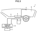
- FIG. 3 is a schematic view that illustrates another example of the configuration of the vehicular display system according to the first embodiment.
- FIG. 4 is a diagram that illustrates an example of video data captured by a rear camera in the vehicular display system according to the first embodiment.
- FIG. 5 is a diagram that illustrates an example of the video displayed on a rearview monitor in the vehicular display system according to the first embodiment.
- FIG. 6 is a diagram that illustrates an example of a first clipping-range definition table in the vehicular display system according to the first embodiment.
- FIG. 7 is a diagram that illustrates another example of the first clipping-range definition table of the vehicular display system according to the first embodiment.
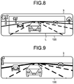
- FIG. 8 is a diagram that illustrates another example of the video displayed in the rearview monitor in the vehicular display system according to the first embodiment.
- FIG. 9 is a diagram that illustrates another example of the video displayed in the rearview monitor in the vehicular display system according to the first embodiment.
- FIG. 10 is a flowchart that illustrates an example of flow of processes in the vehicular display system according to the first embodiment.
- FIG. 11 is a flowchart that illustrates another example of the flow of the processes by the vehicular display system according to the first embodiment.
- FIG. 12 is a block diagram that illustrates an example of the configuration of the vehicular display system according to a second embodiment.
- FIG. 13 is a schematic view that illustrates eye sensors and the rearview monitor in the vehicular display system according to the second embodiment.
- FIG. 14 is a flowchart that illustrates an example of the flow of the processes by the vehicular display system according to the second embodiment.
- FIG. 15 is a block diagram that illustrates an example of the configuration of the vehicular display system according to a third embodiment.
- FIG. 16 is a diagram that illustrates an example of a second clipping-range definition table of the vehicular display system according to the third embodiment.
- FIG. 17 is a flowchart that illustrates an example of the flow of the processes by the vehicular display system according to the third embodiment.
- FIG. 18 is a diagram that illustrates an example of the video data that is captured by the rear camera in the vehicular display system according to the third embodiment.
- FIG. 19 is a diagram that illustrates an example of the video displayed in the rearview monitor in the vehicular display system according to the third embodiment.
- FIG. 20 is a schematic view that illustrates movements of a driver's head detected by the vehicular display system according to a fourth embodiment.
- FIG. 21 is a schematic view that illustrates the movement of the driver's head detected by the vehicular display system according to a fifth embodiment.
- FIG. 22 is a flowchart that illustrates an example of the flow of the processes of the vehicular display system according to the fifth embodiment.
- FIG. 23 is a diagram that illustrates an example of the video data captured by the rear camera in the vehicular display system according to the fifth embodiment.
- FIG. 24 is a diagram that illustrates an example of the video displayed in the rearview monitor in the vehicular display system according to the fifth embodiment.
- FIG. 25 is a diagram that illustrates another example of the video displayed in the rearview monitor in the vehicular display system.
- FIG. 1 is a schematic view that illustrates an example of a configuration of the vehicular display system according to a first embodiment.
- FIG. 2 is a block diagram that illustrates an example of the configuration of the vehicular display system according to the first embodiment.
- FIG. 3 is a schematic view that illustrates another example of the configuration of the vehicular display system according to the first embodiment.
- the vehicular display system 1 includes a rear camera 2 , a rearview monitor (display) 3 , a sensor (detecting unit) 4 , and the vehicular display control device 10 .
- the vehicular display system 1 causes the rearview monitor 3 to display video data 120 that is clipped from captured video data 100 , the video data 120 being clipped in a wider range as a frequency of movement of a driver's head is higher.
- the vehicular display system 1 causes the rearview monitor 3 to display video data 130 that is clipped from the captured video data 100 , the video data 130 being clipped in a narrower range as the frequency of the movement of the driver's head is lower.
- the rear camera 2 is provided in a rear part of the vehicle to capture video data of the rear view of the vehicle.
- FIG. 4 is a diagram that illustrates an example of the video data captured by the rear camera in the vehicular display system according to the first embodiment. As illustrated in FIG. 4 , the rear camera 2 captures the video data for a range including a displayed range of the rearview monitor 3 . In other words, the rear camera 2 captures the video data for a range including a non-displayed range of the rearview monitor 3 .
- the rear camera 2 has a horizontal angle of view in a range of, for example, 30 to 60°, and a vertical angle of view in a range of, for example, 5 to 20°.
- the rear camera 2 is capable of capturing the video in a wider range than the range displayed in the rearview monitor 3 .
- the video captured by the rear camera 2 is clipped by a video data generating unit 33 of a controller 30 in the vehicular display control device 10 in such a range that the driver of the vehicle may properly recognize the rear view by using the rearview monitor 3 , and displayed in the rearview monitor 3 .
- the rear camera 2 outputs the captured video data 100 to a video acquiring unit 31 of the controller 30 in the vehicular display control device 10 .
- the rearview monitor 3 is an electronic rearview mirror, for example. In a case of using the rearview monitor 3 as an electronic rearview mirror, it does not matter whether or not a half mirror is provided for checking the rear view according to optical reflection.
- the rearview monitor 3 is, for example, a display including a liquid crystal display (LCD: Liquid Crystal Display), an organic EL (Organic Electro-Luminescence) display, or the like.
- the rearview monitor 3 is provided at a position easily viewable by the driver. According to the present embodiment, as illustrated in FIG. 1 , the rearview monitor 3 is positioned in an upper part of center in a windshield S in a vehicle width direction in front of the driver. As illustrated in FIG. 3 , the rearview monitor 3 may be positioned in an upper part of center in a dashboard D in the vehicle width direction.
- the rearview monitor 3 displays the video of the rear view of the vehicle based on video signals output from a display controller 34 of the controller 30 in the vehicular display control device 10 .
- the rearview monitor 3 displays video data 110 that is rear view video illustrated in FIG. 5 .
- FIG. 5 is a diagram that illustrates an example of the video displayed in the rearview monitor in the vehicular display system according to the first embodiment.
- the video data 110 illustrated in FIG. 5 is displayed in a normal clipping range, i.e., a range equivalent to a range viewed with a conventional optical rearview mirror.
- a sensor 4 detects the driver's action to change a range of view with respect to the rearview monitor 3 .
- the sensor 4 detects the driver's head movement with respect to the rearview monitor 3 .
- the sensor 4 detects the driver's head movement to change the range of view with respect to the installation position of the rearview monitor 3 as if a conventional optical rearview mirror is installed at the installation position of the rearview monitor 3 .
- the sensor 4 is a sensor that detects the movement in a non-contact manner, such as an image sensor (camera), an infrared sensor, an ultrasound sensor, or a temperature sensor.
- the sensor 4 outputs a detection result to a frequency detecting unit 32 .
- a range of view of a conventional optical mirror is explained.
- the conventional optical mirror when a driver moves his head with respect to the conventional optical mirror, the range of view becomes wider in a direction opposite to a direction in which the head has moved. More specifically, with the conventional optical mirror, when the driver moves his head in a right direction with respect to the conventional optical mirror, the range of view becomes wider in a left direction. With the conventional optical mirror, when the driver moves his head in the left direction with respect to the conventional optical mirror, the range of view becomes wider in the right direction. With the conventional optical mirror, when the driver moves his head in an upward direction with respect to the conventional optical mirror, the range of view becomes wider in a downward direction. With the conventional optical mirror, when the driver moves his head in the downward direction with respect to the conventional optical mirror, the range of view becomes wider in the upward direction.
- the vehicular display control device 10 includes a storage 20 and the controller 30 .
- the storage 20 stores data required for various types of processing by the vehicular display control device 10 and various processing results.
- the storage 20 is a storage device, for example, a semiconductor memory device such as a RAM (Random Access Memory), a ROM (Read Only Memory), or a flash memory (Flash Memory), a hard disk, an optical disk, or an external storage device via a network. Alternatively, it may be an external storage device wirelessly connected via a communication device not shown.
- a first clipping-range definition table 21 is stored in the storage 20 .
- the first clipping-range definition table 21 defines a clipping range of the captured video data 100 for each frequency of the movement of the driver's head.
- the first clipping-range definition table 21 defines that a wider range is clipped as the frequency of the movement of the driver's head is higher and a narrower range is clipped as the frequency of the movement of the driver's head is lower. For example, the number of times of the movement of the head per a predetermined time or the accumulated number of the movement of the head is used as the frequency of the movement of the driver's head.
- FIG. 6 is a diagram that illustrates an example of the first clipping-range definition table in the vehicular display system according to the first embodiment.
- the frequency of the movement of the driver's head is defined by the number of times of the movement of the driver's head per a predetermined time.
- the first clipping-range definition table 21 defines that the clipping range is “narrower” than the normal clipping range when the frequency of the movement of the driver's head is “zero in ten seconds”, defines that the clipping range is “normal” when the frequency of the movement of the driver's head is “one or more times and less than twice in ten seconds”, and defines that the clipping range is “wider” than the normal clipping range when the frequency of the movement of the driver's head is “two or more times in ten seconds”.
- “wider” than the normal clipping range means that, for example, the clipping range is wider than the normal clipping range by approximately 20%.
- “narrower” than the normal clipping range means that, for example, the clipping range is narrower than the normal clipping range by approximately 20%.
- FIG. 7 is a diagram that illustrates another example of the first clipping-range definition table of the vehicular display system according to the first embodiment.
- the frequency of the movement of the head is defined by the accumulated number of times of the movement of the driver's head.
- the accumulated number of times of the movement of the driver's head is, for example, a count of the movement of the driver's head in a short time interval, approximately several seconds. In other words, when there is no movement of the driver's head for more than several seconds, the counter is reset.
- the first clipping-range definition table 21 defines that the clipping range is “narrower” than the normal clipping range when the frequency of the movement of the driver's head is “zero as accumulated”, defines that the clipping range is “normal” when the frequency of the movement of the driver's head is “one or more times and less than ten times as accumulated”, and defines that the clipping range is “wider” than the normal clipping range when the frequency of the movement of the driver's head is “ten or more times as accumulated”.
- “wider” than the normal clipping range means that, for example, the clipping range is wider than the normal clipping range by approximately 20%.
- “narrower” than the normal clipping range means that, for example, the clipping range is narrower than the normal clipping range by approximately 20%.
- the controller 30 is an arithmetic processing device configured by using, for example, a CPU (Central Processing Unit).
- the controller 30 includes the video acquiring unit 31 , the frequency detecting unit 32 , the video data generating unit 33 , and the display controller 34 .
- the controller 30 executes commands included in programs that are stored in the storage 20 .
- the video acquiring unit 31 acquires video of captured rear view of the vehicle.
- the captured video data 100 acquired by the video acquiring unit 31 is, for example, video data that is a series of images in 60 frames per second. According to the present embodiment, the video acquiring unit 31 acquires the captured video data 100 output from the rear camera 2 .
- the video acquiring unit 31 outputs the captured video data 100 acquired to the video data generating unit 33 .
- the frequency detecting unit 32 detects the frequency of the driver's action to change the range of view in accordance with a detection result of the sensor 4 . According to the present embodiment, the frequency detecting unit 32 detects the frequency of the movement of the driver's head in accordance with a detection result of the sensor 4 . The frequency detecting unit 32 outputs a detection result thereof to the video data generating unit 33 .
- the video data generating unit 33 acquires the captured video data 100 from the rear camera 2 and generates the video data 110 , the video data 120 , or the video data 130 to be displayed in the rearview monitor 3 . More specifically, the video data generating unit 33 clips the range for being displayed in the rearview monitor 3 in the captured video data 100 .
- the video data generating unit 33 When the frequency of the movement of the driver's head is zero, i.e., when the movement of the driver's head is zero or more and less than a predetermined value, the video data generating unit 33 outputs the video data 110 illustrated in FIG. 5 , which is clipped in the captured video data 100 in the normal clipping range, to the display controller 34 .
- the video data generating unit 33 clips central part of the captured video data 100 surrounded by a solid line in FIG. 4 as the video data 110 for the normal clipping range.
- the normal clipping range is previously stored in the storage 20 .
- the video data generating unit 33 outputs the clipped video data 110 to the display controller 34 .
- the normal clipping range is a viewable range when the driver squarely looks at the conventional optical rearview mirror.
- the captured video data 100 includes a range that is not viewable when the driver squarely looks at the conventional optical rearview mirror but viewable when the point of view is shifted or the angle thereof is adjusted, and ranges outside thereof.
- the video data generating unit 33 clips the captured video data 100 in a wider range as the frequency of the movement of the driver's head detected by the frequency detecting unit 32 is higher to generate the video data 120 , and clips it in a narrower range as the frequency of the movement of the driver's head is lower to generate the video data 130 . More specifically, the video data generating unit 33 performs the clipping by changing the clipping range of the captured video data 100 in accordance with the frequency of the movement of the driver's head corresponding to the first clipping-range definition table 21 , generates the video data 120 or the video data 130 , and outputs the video data 120 or the video data 130 to the display controller 34 .
- FIG. 8 is a diagram that illustrates another example of the video displayed in the rearview monitor in the vehicular display system according to the first embodiment.
- the video data 120 illustrates a border line L indicating the range of view of the video data 110 for the normal clipping range. By seeing the border line L, the driver may easily recognize that the video data 120 displayed in the rearview monitor 3 has a wide range of view as compared with the video data 110 .
- FIG. 9 is a diagram that illustrates another example of the video displayed in the rearview monitor in the vehicular display system according to the first embodiment.
- the video data 130 has a narrower range of view than that of the video data 110 , and captured objects are enlarged.
- the video data generating unit 33 generates the video data 110 , the video data 120 , or the video data 130 by changing the clipping range such that the range required by the driver is included in accordance with the frequency of the movement of the driver's head.
- the display controller 34 causes the rearview monitor 3 to display the video data 110 , the video data 120 , or the video data 130 generated by the video data generating unit 33 .
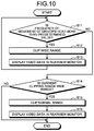
- FIG. 10 is a flowchart that illustrates an example of the flow of the processes in the vehicular display system according to the first embodiment.
- the controller 30 continuously acquires the frequency of the movement of the driver's head. More specifically, the controller 30 uses the frequency detecting unit 32 to monitor the frequency of the movement of the driver's head on a constant basis in accordance with a detection result of the sensor 4 .
- the controller 30 determines whether the frequency of the movement of the driver's head is more than a predetermined value (Step S 11 ). More specifically, the controller 30 determines whether the frequency of the movement of the driver's head detected by the frequency detecting unit 32 is more than the predetermined value. According to the present embodiment, the predetermined value is twice in ten seconds. When it is determined that the frequency of the movement of the driver's head is not more than the predetermined value (No at Step S 11 ), the controller 30 proceeds to Step S 14 . When it is determined that the frequency of the movement of the driver's head is more than the predetermined value (Yes at Step S 11 ), the controller 30 proceeds to Step S 12 . In this case, the frequency of the movement of the driver's head is equivalent to two or more times in ten seconds.
- the controller 30 clips a wide range (Step S 12 ). More specifically, the controller 30 uses the video data generating unit 33 to generate the video data 120 that is clipped in the captured video data 100 in a range wider than the normal clipping range.
- the controller 30 displays the generated video data 120 in the rearview monitor 3 (Step S 13 ). More specifically, the controller 30 uses the display controller 34 to display the video data 120 in the rearview monitor 3 .
- the controller 30 determines whether the current clipping range is a wide range (Step S 14 ). More specifically, when the current clipping range is a range wider than the normal clipping range (Yes at Step S 14 ), the controller 30 proceeds to Step S 15 . When the current clipping range is not a range wider than the normal clipping range (No at Step S 14 ), the controller 30 terminates the process.
- the controller 30 clips the normal range (Step S 15 ). More specifically, the controller 30 uses the video data generating unit 33 to generate the video data 110 that is clipped in the captured video data 100 for the normal clipping range.
- the controller 30 displays the generated video data 110 in the rearview monitor 3 (Step S 16 ). More specifically, the controller 30 uses the display controller 34 to display the video data 110 in the rearview monitor 3 .
- the controller 30 causes the rearview monitor 3 to display the video data 120 that is clipped in a range wider than the normal clipping range.
- the controller 30 causes the rearview monitor 3 to display the video data 110 that is clipped in the normal clipping range.
- the controller 30 repeats this process in a predetermined interval, e.g., in each frame or in predetermined frames.
- the controller 30 may cause the rearview monitor 3 to display the video data 110 clipped in the normal clipping range after the video data 120 clipped in a range wider than the normal clipping range is displayed in the rearview monitor 3 , e.g. for 5 seconds.
- the rearview monitor 3 displays the video data 120 clipped in a range wider than the normal clipping range for approximately five seconds and then the rearview monitor 3 displays the video data 110 clipped in the normal clipping range.
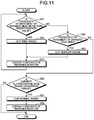
- FIG. 11 is a flowchart that illustrates another example of the flow of the processes by the vehicular display system according to the first embodiment.
- the flowchart illustrated in FIG. 11 corresponds to the first clipping-range definition table 21 illustrated in FIG. 6 .
- Step S 21 , Step S 22 , and Step S 26 to Step S 28 the same processes as those at Step S 11 , Step S 12 , and Step S 14 to Step S 16 in the flowchart illustrated in FIG. 10 are performed.
- the controller 30 displays the video data in the rearview monitor 3 (Step S 23 ). More specifically, the controller 30 uses the display controller 34 to display the video data 120 or the video data 130 in the rearview monitor 3 .
- the controller 30 determines whether the frequency of the movement of the driver's head is zero in ten seconds (Step S 24 ). More specifically, the controller 30 determines whether the frequency of the movement of the driver's head detected by the frequency detecting unit 32 is zero in ten seconds. When it is determined that the frequency of the movement of the driver's head is not zero in ten seconds (No at Step S 24 ), the controller 30 proceeds to Step S 26 . In this case, the frequency of the movement of the driver's head is equivalent to one or more times and less than twice in ten seconds. When it is determined that the frequency of the movement of the driver's head is zero in ten seconds (Yes at Step S 24 ), the controller 30 proceeds to Step S 25 . Zero mentioned here is a value smaller than the predetermined value at Step S 21 , and it includes a state where there is little movement of the head.
- the controller 30 clips a narrow range (Step S 25 ). More specifically, the controller 30 uses the video data generating unit 33 to generate the video data 130 that is clipped in the captured video data 100 in a range narrower than the normal clipping range.
- the controller 30 causes the rearview monitor 3 to display the video data 130 that is clipped in a range narrower than the normal clipping range.
- the flow of the processes by the controller 30 may be processes in accordance with a flowchart that corresponds to the first clipping-range definition table 21 illustrated in FIG. 7 .
- the rearview monitor 3 displays the video data 120 clipped in a range wider than the normal clipping range.
- the rearview monitor 3 displays the video data 130 that is clipped in a range narrower than the normal clipping range.
- the rearview monitor 3 displays the video data 110 that is clipped in the normal clipping range.
- the driver who used to use a conventional optical rearview mirror may move his head unconsciously for changing the range of view so as to obtain necessary information. Therefore, according to the present embodiment, the unconscious movement of the driver's head with respect to the installation position of the rearview monitor 3 for changing the range of view as if a conventional optical mirror is installed at the installation position of the rearview monitor 3 is detected.
- the rearview monitor 3 is capable of displaying the video data 110 , the video data 120 , or the video data 130 in accordance with the frequency of the unconscious movement of the head for changing the range of view by the driver for a conventional optical rearview mirror.
- the rearview monitor 3 when the frequency of the movement of the driver's head is high, e.g., during driving in a city, the rearview monitor 3 is capable of displaying the rear view of the vehicle in a wider range.
- the rearview monitor 3 when the frequency of the movement of the driver's head is low, e.g., during driving on an express way, the rearview monitor 3 is capable of displaying the rear view of the vehicle in a narrow range in an enlarged manner.
- the frequency of the movement of the driver's head when the frequency of the movement of the driver's head is low, the inter-vehicular distance with a vehicle behind may be easily recognized.
- a vehicle behind in a long distance may be easily recognized.
- the rearview monitor 3 when the frequency of the movement of the driver's head is more than a predetermined value, the rearview monitor 3 displays the video data 120 clipped in a range wider than the normal clipping range. Then, for example, after a lapse of five seconds, the rearview monitor 3 may display the video data 110 clipped in the normal clipping range. Therefore, according to the present embodiment, an amount of information displayed in the rearview monitor 3 may be increased only when the driver takes action to change the range of view. Thus, according to the present embodiment, the video data 120 with an increased amount of information is displayed in the rearview monitor 3 with limited timings to suppress an amount of time for checking the rear view in the rearview monitor 3 by the driver.
- FIG. 12 is a block diagram that illustrates an example of the configuration of the vehicular display system according to a second embodiment.
- FIG. 13 is a schematic view that illustrates eye sensors and the rearview monitor in the vehicular display system according to the second embodiment.
- FIG. 14 is a flowchart that illustrates an example of the flow of the processes by the vehicular display system according to the second embodiment.
- the basic configuration of the vehicular display system 1 A is the same as that of the vehicular display system 1 according to the first embodiment. In the following explanation, detailed explanation is omitted for the same components as those in the vehicular display system 1 .
- the vehicular display system 1 A is different from the vehicular display system 1 according to the first embodiment in that it includes an eye sensor 5 and a vehicular display control device 10 A includes an eye detecting unit 36 A.
- the vehicular display system 1 A is different from the vehicular display system 1 according to the first embodiment in a process of a controller 30 A.
- the vehicular display system 1 A includes the rear camera 2 , the rearview monitor 3 , the sensor 4 , the eye sensor 5 , and the vehicular display control device 10 A.
- the eye sensor 5 detects line of sight of a driver.
- the eye sensor 5 is provided near the rearview monitor 3 such that it is faced to the driver's seat.
- the eye sensor 5 is provided one the rearview monitor 3 .
- the eye sensor 5 includes a pair of infrared cameras 51 and a pair of infrared-light emitting units 52 comprising multiple infrared LEDs.
- the infrared-light emitting units 52 emit infrared light toward the driver's face and the infrared cameras 51 capture an image of the driver's eyes.
- the eye sensor 5 may have a different configuration having the same functionality.
- the eye sensor 5 outputs a detection result to the eye detecting unit 36 A.
- the eye detecting unit 36 A detects whether the driver's eyes turn to the rearview monitor 3 . More specifically, the eye detecting unit 36 A detects the positions of corneal reflexes and pupils of the driver in the captured video by the infrared cameras 51 and determines whether the driver's eyes turn to the rearview monitor 3 . The eye detecting unit 36 A outputs a detection result to the video data generating unit 33 .
- Step S 32 to Step S 34 and Step S 35 to Step S 37 the same processes as those at Step S 11 to Step S 13 and Step S 14 to Step S 16 according to the first embodiment are performed.
- the controller 30 determines whether the driver's eyes turn to the rearview monitor 3 (Step S 31 ). More specifically, based on the detection result of the eye detecting unit 36 A, the controller 30 determines whether the driver's eyes turn to the rearview monitor 3 . When it is determined that the driver's eyes do not turn to the rearview monitor 3 (No at Step S 31 ), the controller 30 proceeds to Step S 35 . When it is determined that the driver's eyes turn to the rearview monitor 3 (Yes at Step S 31 ), the controller 30 proceeds to Step S 32 .
- the rearview monitor 3 may display the video data 120 that is clipped in a wide range.
- the rearview monitor 3 may display the video data 120 that is clipped in a wide range only when the driver looks at the rearview monitor 3 .
- FIG. 15 is a block diagram that illustrates an example of the configuration of the vehicular display system according to a third embodiment.
- FIG. 16 is a diagram that illustrates an example of a second clipping-range definition table of the vehicular display system according to the third embodiment.
- FIG. 17 is a flowchart that illustrates an example of the flow of the processes by the vehicular display system according to the third embodiment.
- FIG. 18 is a diagram that illustrates an example of the video data that is captured by the rear camera in the vehicular display system according to the third embodiment.
- FIG. 19 is a diagram that illustrates an example of the video displayed in the rearview monitor in the vehicular display system according to the third embodiment.
- the basic configuration of the vehicular display system 1 B is the same as that of the vehicular display system 1 according to the first embodiment.
- a vehicular display control device 10 B is different from the vehicular display control device 10 according to the first embodiment in that it includes a vehicle-speed acquiring unit 35 B.
- the vehicular display system 1 B is different from the vehicular display system 1 according to the first embodiment in a process of a controller 30 B.
- a second clipping-range definition table 22 is stored in the storage 20 .
- the second clipping-range definition table 22 defines the clipping range of the captured video data 100 for each vehicle speed.
- the second clipping-range definition table 22 defines that a wider range is clipped as a vehicle speed is lower.
- the second clipping-range definition table 22 defines that the clipping range is “wider by 130%” than the normal clipping range when the vehicle speed is “less than 20 km/h”, defines that the clipping range is “wider by 120%” than the normal clipping range when the vehicle speed is “equal to or more than 20 km/h and less than 60 km/h”, and defines that the clipping range is “wider by 110%” than the normal clipping range when the vehicle speed is “equal to or more than 60 km/h”.
- a video data generating unit 33 B clips, in the captured video data 100 , the clipping range for the case in which the frequency of the movement of the head detected by the frequency detecting unit 32 is high wider, as the vehicle speed acquired by the vehicle-speed acquiring unit 35 B is lower.
- the video data generating unit 33 B in the controller 30 clips the captured video data 100 in a wider range as the vehicle speed is lower.
- the driver can check the rear view appropriately in the rearview monitor 3 in which the wide range is displayed.
- the vehicle-speed acquiring unit 35 B is connected to a CAN (Controller Area Network) included in a vehicle to acquire OBD (On Board Diagnosis) II data, or the like, thereby acquiring vehicle speed information.
- the vehicle-speed acquiring unit 35 B outputs the acquired vehicle speed information to the video data generating unit 33 B.
- Step S 41 and Step S 48 to Step S 50 the same processes as those at Step S 11 and Step S 14 to Step S 16 according to the first embodiment are performed.
- the controller 30 B determines whether the vehicle speed is less than 20 km/h (Step S 42 ). When it is determined that the vehicle speed is less than 20 km/h (Yes at Step S 42 ), the controller 30 B proceeds to Step S 43 . When it is determined that the vehicle speed is not less than 20 km/h (No at Step S 42 ), the controller 30 B proceeds to Step S 44 .
- the controller 30 B clips a range that is wider by 130% (Step S 43 ). More specifically, the controller 30 B uses the video data generating unit 33 B to generate video data 120 A that is clipped in the captured video data 100 in a range wider than the normal clipping range by 130%.
- the controller 30 B determines whether the vehicle speed is equal to or more than 20 km/h and less than 60 km/h (Step S 44 ). When it is determined that the vehicle speed is equal to or more than 20 km/h and less than 60 km/h (Yes at Step S 44 ), the controller 30 B proceeds to Step S 45 . When it is determined that the vehicle speed is not equal to or more than 20 km/h and less than 60 km/h (No at Step S 44 ), the controller 30 B proceeds to Step S 46 .
- the controller 30 B clips a range that is wider by 120% (Step S 45 ). More specifically, the controller 30 B uses the video data generating unit 33 B to generate video data 120 B that is clipped in the captured video data 100 in a range wider than the normal clipping range by 120%.
- the controller 30 B clips a range that is wider by 110% (Step S 46 ). More specifically, the controller 30 B uses the video data generating unit 33 B to generate video data 120 C that is clipped in the captured video data 100 in a range wider than the normal clipping range by 110%.
- the controller 30 B display the video data in the rearview monitor 3 (Step S 47 ). More specifically, the controller 30 uses the display controller 34 to display the video data 120 A, the video data 120 B, or the video data 120 C in the rearview monitor 3 .
- the controller 30 B causes the rearview monitor 3 to display the video data 120 A illustrated in FIG. 19 , which is clipped in a range wider than the normal clipping range by 130% in the captured video data 100 illustrated in FIG. 18 .
- the controller 30 B causes the rearview monitor 3 to display the video data 120 B that is clipped in a range wider than the normal clipping range by 120% in the captured video data 100 illustrated in FIG. 18 .
- the controller 30 B causes the rearview monitor 3 to display the video data 120 C that is clipped in a range wider than the normal clipping range by 110% in the captured video data 100 illustrated in FIG. 18 .
- the controller 30 B causes the rearview monitor 3 to display the video data 110 that is clipped in the captured video data 100 illustrated in FIG. 18 in the normal clipping range.
- the rearview monitor 3 displays the video data 120 A, the video data 120 B, or the video data 120 C that is clipped in a wider range as the vehicle speed is lower.
- information may be displayed with the appropriate range for the driver in accordance with the vehicle speed.
- the driver is capable of checking the surrounding areas of the vehicle appropriately.
- FIG. 20 is a schematic view that illustrates the movement of the driver's head detected by the vehicular display system according to the fourth embodiment.
- the vehicular display system 1 is different from the first embodiment in that the frequency detecting unit 32 detects the movement of the driver's head to the right or to the left (in a right-and-left direction).
- the frequency detecting unit 32 detects the frequency of the movement of the driver's head in a right direction or in a left direction.
- a reference position HO with little movement is set as a position of the driver's head, and a movement of an intermediate position between the eyes of the driver in a right direction with the reference position HO as a center is referred to as a rightward movement, and a movement thereof in a left direction is referred to as a leftward movement.
- the reference position HO the position with little movement of the head may be specified as the reference position HO based on a detection result of the movement of the driver's head by the sensor 4 .
- the reference position HO may be calculated based on the position of the driver's seat, the posture of the driver, and the position of the rearview monitor 3 .
- the sensor 4 detects the movement of the driver's head in a right-and-left direction.
- the frequency detecting unit 32 detects the frequency of the movement of the driver's head in a right-and-left direction based on the detection results of the sensor 4 .
- the video data generating unit 33 generates the video data 110 , the video data 120 , or the video data 130 by changing the clipping range such that it includes the required range for the driver based on the frequency of the movement of the driver's head in a right-and-left direction, detected by the frequency detecting unit 32 .
- driver's action to change the range of view is detectable more accurately. According to the present embodiment, it is possible to avoid switching of the video displayed in the rearview monitor 3 due to an action different from the action for changing the range of view by the driver. In this manner, according to the present embodiment, more appropriate and required information for the driver may be displayed based on the frequency of the movement of the driver's head in a right-and-left direction. Thus, according to the present embodiment, the driver is capable of checking the surrounding areas of the vehicle more appropriately.
- FIG. 21 is a schematic view that illustrates the movement of the driver's head detected by the vehicular display system according to a fifth embodiment.
- FIG. 22 is a flowchart that illustrates an example of the flow of the processes of the vehicular display system according to the fifth embodiment.
- FIG. 23 is a diagram that illustrates an example of the video data captured by the rear camera in the vehicular display system according to the fifth embodiment.
- FIG. 24 is a diagram that illustrates an example of the video displayed in the rearview monitor in the vehicular display system according to the fifth embodiment.
- the vehicular display system 1 according to the present embodiment is different from the vehicular display system 1 according to the first embodiment in a process of the controller 30 .
- the sensor 4 detects the movement of the driver's head and the direction of the movement.
- the reference position HO of the driver's head is set, a right side of the intermediate position between the eyes of the driver at the reference position HO is set as a first range A 1 , a left side is set as a second range A 2 , the upper side is set as a third range A 3 , and the lower side is set as a fourth range A 4 .
- the sensor 4 detects a movement in a direction from the reference position HO, which is the intermediate position between the eyes of the driver, to the first range A 1 as a rightward movement of the driver's head.
- the sensor 4 detects a movement in a direction from the reference position HO, which is the intermediate position of the eyes of the driver, to the second range A 2 as a leftward movement of the driver's head.
- the sensor 4 detects a movement in a direction from the reference position HO, which is the intermediate position of the eyes of the driver, to the third range A 3 as a upward movement of the driver's head.
- the sensor 4 detects a movement in a direction from the reference position HO, which is the intermediate position of the eyes of the driver, to the fourth range A 4 as a downward movement of the driver's head.
- the frequency detecting unit 32 Based on the detection results of the sensor 4 , the frequency detecting unit 32 detects the frequency in each direction of the movement of the driver's head. According to the present embodiment, the frequency detecting unit 32 detects the movement of the driver's head separately in a right direction, a left direction, an upward direction, and a downward direction, thereby detecting the frequency of the movement of the driver's head in each direction.
- the video data generating unit 33 clips the captured video data 100 in a range that is shifted from the normal clipping range in a direction opposite to the direction of the movement of the driver's head with high frequency, thereby generating video data 120 D, video data 120 E, video data 120 F, or video data 120 G.
- the video data generating unit 33 shifts the normal clipping range within the range of the captured video data 100 .
- the video data generating unit 33 clips the captured video data 100 by shifting the normal clipping range by a predetermined number of pixels in the direction opposite to the direction of the movement of the driver's head with high frequency.
- the video data generating unit 33 clips the video data 120 D that is wider than the normal clipping range on the left side. In this way, when the driver's head in the vehicle moves with high frequency in a right direction, the video data generating unit 33 clips the captured video data 100 by shifting the clipping range in a left direction as compared with the normal clipping range.
- the video data generating unit 33 clips the video data 120 E that is wider than the normal clipping range on the right side. In this way, when the driver's head in the vehicle moves with high frequency in a left direction, the video data generating unit 33 clips the captured video data 100 by shifting the clipping range in a right direction as compared with the normal clipping range.
- the video data generating unit 33 clips the video data 120 F that is wider than the normal clipping range on the lower side. In this way, when the driver's head in the vehicle moves with high frequency in an upward direction, the video data generating unit 33 clips the captured video data 100 by shifting the clipping range in a downward direction as compared with the normal clipping range.
- the video data generating unit 33 clips the video data 120 G that is wider than the normal clipping range on the upper side. In this way, when the driver's head in the vehicle moves with high frequency in a downward direction, the video data generating unit 33 clips the captured video data 100 by shifting the clipping range in an upward direction as compared with the normal clipping range.
- Step S 53 and Step S 54 to Step S 56 the same processes as those at Step S 13 and Step S 14 to Step S 16 according to the first embodiment are performed.
- the controller 30 determines whether the frequency of the movement of the head in one direction is more than a predetermined value (Step S 51 ). More specifically, the controller 30 determines whether the frequency of the movement of the head in one direction, detected by the frequency detecting unit 32 , is more than a predetermined value. When it is determined that the frequencies of the movements of the head in all the directions are less than the predetermined value (No at Step S 51 ), the controller 30 proceeds to Step S 54 . When it is determined that the frequency of the movement of the head in one direction is more than the predetermined value (Yes at Step S 51 ), the controller 30 proceeds to Step S 52 .
- the controller 30 clips a wider range in the video data in the direction opposite to the direction of the movement of the driver's head with high frequency (Step S 52 ). More specifically, the controller 30 uses the video data generating unit 33 to clip the captured video data 100 in the clipping range that is shifted from the normal clipping range to generate the video data 120 D, the video data 120 E, the video data 120 F, or the video data 120 G.
- Step S 51 the controller 30 determines that the frequency of the movement of the head in a right direction is equal to or more than the predetermined value (Yes at Step S 51 ). Then, at Step S 52 , the controller 30 uses the video data generating unit 33 to clip the captured video data 100 in the clipping range that is shifted to the left side from the normal clipping range to generate the video data 120 D that is wide on the left side, as illustrated in FIG. 24 .
- the video data 120 D, the video data 120 E, the video data 120 F, or the video data 120 G is displayed, which is clipped from the captured video data 100 by shifting the clipping range in the direction opposite to the direction of the movement of the driver's head with high frequency.
- appropriate and required information for the driver may be displayed wider in the direction at which the driver desires to look.
- the driver is capable of checking the surrounding areas of the vehicle appropriately.
- Each component of the vehicular display system 1 illustrated is functionally conceptual and does not necessarily need to be physically configured as illustrated in the drawings. That is, the specific configuration of each device is not limited to that illustrated in the drawings, and all or part of it may be separated or integrated functionally or physically in any unit in accordance with a processing load or a usage situation of the device.
- the configuration of the vehicular display system 1 is implemented as for example software by using programs, or the like, loaded into a memory. According to the above-described embodiment, it is explained as functional blocks that are implemented due to cooperation of the hardware or the software. That is, the functional blocks may be implemented in various forms with only hardware, only software, or a combination of them.
- the components described above include the ones that may be easily reached by a person skilled in the art and substantially the same ones. Furthermore, the above-described components may be combined as appropriate. Furthermore, the components may be omitted, replaced, or modified in various manners without departing from the scope of the present application.
- the detecting unit is explained as the sensor, this is not a limitation on the detecting unit.
- the detecting unit may detect a movement of the driver's head in video of the driver captured by a camera installed near the driver's seat inside the vehicle.
- the sensor 4 may detect any driver's action to change the range of view with respect to the rearview monitor 3 , and it is not limited to the one for detecting the movement of the driver's head.
- the sensor 4 may detect movement of the driver's shoulder or movement of the driver's neck.
- the sensor 4 may avoid detecting small movement among the movement of the driver's head. For example, the sensor 4 may detect a situation where the driver's head moves in more than a predetermined distance or a situation where it moves with more than a predetermined angle. Thus, a situation where the driver's head moves due to vibration of the vehicle, or the like, may be prevented from being detected as the driver's action for changing the range of view in the vehicle.
- the display controller 34 may display the video data 120 with coloring the area outside the normal video data 110 in translucence with a predetermined degree of transparency, as illustrated in FIG. 25 .
- FIG. 25 is a diagram that illustrates another example of the video displayed in the rearview monitor in the vehicular display system.
- the vehicular display system 1 makes it possible to easily recognize that the video data 120 clipped in a range wider than the normal clipping range is being displayed.
- the driver is capable of easily recognizing that the video data 120 displayed in the rearview monitor 3 has a wider range of view than the video data 110 .
Landscapes
- Engineering & Computer Science (AREA)
- Multimedia (AREA)
- Signal Processing (AREA)
- Physics & Mathematics (AREA)
- General Physics & Mathematics (AREA)
- Theoretical Computer Science (AREA)
- Computer Vision & Pattern Recognition (AREA)
- Mechanical Engineering (AREA)
- General Health & Medical Sciences (AREA)
- Human Computer Interaction (AREA)
- Health & Medical Sciences (AREA)
- Ophthalmology & Optometry (AREA)
- Psychiatry (AREA)
- Social Psychology (AREA)
- Closed-Circuit Television Systems (AREA)
- Controls And Circuits For Display Device (AREA)
- Fittings On The Vehicle Exterior For Carrying Loads, And Devices For Holding Or Mounting Articles (AREA)
Applications Claiming Priority (3)
| Application Number | Priority Date | Filing Date | Title |
|---|---|---|---|
| JP2016-175244 | 2016-09-08 | ||
| JP2016175244A JP6669019B2 (ja) | 2016-09-08 | 2016-09-08 | 車両用表示制御装置、車両用表示システム、車両用表示制御方法およびプログラム |
| PCT/JP2017/015634 WO2018047400A1 (ja) | 2016-09-08 | 2017-04-18 | 車両用表示制御装置、車両用表示システム、車両用表示制御方法およびプログラム |
Related Parent Applications (1)
| Application Number | Title | Priority Date | Filing Date |
|---|---|---|---|
| PCT/JP2017/015634 Continuation WO2018047400A1 (ja) | 2016-09-08 | 2017-04-18 | 車両用表示制御装置、車両用表示システム、車両用表示制御方法およびプログラム |
Publications (2)
| Publication Number | Publication Date |
|---|---|
| US20190075253A1 US20190075253A1 (en) | 2019-03-07 |
| US10715744B2 true US10715744B2 (en) | 2020-07-14 |
Family
ID=61562238
Family Applications (1)
| Application Number | Title | Priority Date | Filing Date |
|---|---|---|---|
| US16/182,710 Active US10715744B2 (en) | 2016-09-08 | 2018-11-07 | Vehicular display control device, vehicular display system, vehicular display control method, and non-transitory storage medium |
Country Status (3)
| Country | Link |
|---|---|
| US (1) | US10715744B2 (ja) |
| JP (1) | JP6669019B2 (ja) |
| WO (1) | WO2018047400A1 (ja) |
Cited By (1)
| Publication number | Priority date | Publication date | Assignee | Title |
|---|---|---|---|---|
| US20220038621A1 (en) * | 2019-05-17 | 2022-02-03 | Samsung Electronics Co., Ltd. | Device for automatically capturing photo or video about specific moment, and operation method thereof |
Families Citing this family (11)
| Publication number | Priority date | Publication date | Assignee | Title |
|---|---|---|---|---|
| JP7296374B2 (ja) | 2018-05-08 | 2023-06-22 | ソニーセミコンダクタソリューションズ株式会社 | 画像処理装置、移動装置、および方法、並びにプログラム |
| JP6921316B2 (ja) * | 2018-05-16 | 2021-08-18 | 三菱電機株式会社 | 車両用画像処理装置および画像処理方法 |
| US10810966B1 (en) * | 2019-01-15 | 2020-10-20 | Ambarella International Lp | Fusion of electronic mirror systems and driver monitoring for increased convenience and added safety |
| JP7442933B2 (ja) * | 2020-03-20 | 2024-03-05 | アルパイン株式会社 | 車両用画像処理装置 |
| EP4131944A4 (en) * | 2020-03-27 | 2023-07-26 | JVCKENWOOD Corporation | DISPLAY CONTROL DEVICE, DISPLAY CONTROL METHOD AND PROGRAM |
| JP7459607B2 (ja) * | 2020-03-27 | 2024-04-02 | 株式会社Jvcケンウッド | 表示制御装置、表示制御方法およびプログラム |
| EP3967552B1 (en) * | 2020-09-11 | 2025-03-19 | Ficosa Adas, S.L.U. | Camera monitoring system for motor vehicles |
| WO2022192663A1 (en) * | 2021-03-12 | 2022-09-15 | Stoneridge, Inc. | Vehicle camera mirror system with adjustable video feed |
| JP7739930B2 (ja) * | 2021-10-19 | 2025-09-17 | トヨタ自動車株式会社 | 車両後方監視システム |
| US12330562B1 (en) * | 2022-06-29 | 2025-06-17 | Amazon Technologies, Inc. | Dynamic camera image presentation in a vehicle |
| JP7694515B2 (ja) * | 2022-09-14 | 2025-06-18 | トヨタ自動車株式会社 | 画像処理装置および画像処理方法 |
Citations (18)
| Publication number | Priority date | Publication date | Assignee | Title |
|---|---|---|---|---|
| JP2005004414A (ja) | 2003-06-11 | 2005-01-06 | Nissan Motor Co Ltd | 車両用運転支援装置 |
| JP2008018760A (ja) | 2006-07-11 | 2008-01-31 | Honda Motor Co Ltd | 運転支援装置 |
| JP2010179850A (ja) | 2009-02-06 | 2010-08-19 | Toyota Motor Corp | 車両用表示装置 |
| US20100214105A1 (en) * | 2009-02-24 | 2010-08-26 | Panasonic Automotive Systems Company Of America, Division Of Panasonic Corporation Of North America | Method of detecting drowsiness of a vehicle operator |
| US20120169875A1 (en) | 2011-01-05 | 2012-07-05 | Denso Corporation | Rearward view assistance apparatus |
| US20130314503A1 (en) * | 2012-05-18 | 2013-11-28 | Magna Electronics Inc. | Vehicle vision system with front and rear camera integration |
| JP2014045265A (ja) | 2012-08-24 | 2014-03-13 | Kyocera Corp | 車載撮像システム |
| US20140214271A1 (en) * | 2013-01-31 | 2014-07-31 | Electronics And Telecommunications Research Institute | Apparatus and method for detecting obstacle adaptively to vehicle speed |
| US20140267727A1 (en) * | 2013-03-14 | 2014-09-18 | Honda Motor Co., Ltd. | Systems and methods for determining the field of view of a processed image based on vehicle information |
| US20150012185A1 (en) * | 2013-07-03 | 2015-01-08 | Volvo Car Corporation | Vehicle system for control of vehicle safety parameters, a vehicle and a method for controlling safety parameters |
| US20150055120A1 (en) * | 2013-08-20 | 2015-02-26 | Ford Global Technologies, Llc | Image system for automotive safety applications |
| US20170001648A1 (en) * | 2014-01-15 | 2017-01-05 | National University Of Defense Technology | Method and Device for Detecting Safe Driving State of Driver |
| US20170132480A1 (en) * | 2015-11-09 | 2017-05-11 | Lg Electronics Inc. | Apparatus for providing around view and vehicle |
| US20170129405A1 (en) * | 2014-08-12 | 2017-05-11 | Sony Corporation | Vehicle display device, display control method, and rearview monitoring system |
| US20170300162A1 (en) * | 2014-11-26 | 2017-10-19 | Lg Electronics Inc. | Electronic device and control method for the electronic device |
| US20170305349A1 (en) * | 2013-03-15 | 2017-10-26 | Mouhamad A. Naboulsi | Safety control system for vehicles |
| US10116873B1 (en) * | 2015-11-09 | 2018-10-30 | Ambarella, Inc. | System and method to adjust the field of view displayed on an electronic mirror using real-time, physical cues from the driver in a vehicle |
| US20190126824A1 (en) * | 2016-04-18 | 2019-05-02 | Sony Corporation | Image display device, image display method, and moving object |
-
2016
- 2016-09-08 JP JP2016175244A patent/JP6669019B2/ja active Active
-
2017
- 2017-04-18 WO PCT/JP2017/015634 patent/WO2018047400A1/ja not_active Ceased
-
2018
- 2018-11-07 US US16/182,710 patent/US10715744B2/en active Active
Patent Citations (19)
| Publication number | Priority date | Publication date | Assignee | Title |
|---|---|---|---|---|
| JP2005004414A (ja) | 2003-06-11 | 2005-01-06 | Nissan Motor Co Ltd | 車両用運転支援装置 |
| JP2008018760A (ja) | 2006-07-11 | 2008-01-31 | Honda Motor Co Ltd | 運転支援装置 |
| JP2010179850A (ja) | 2009-02-06 | 2010-08-19 | Toyota Motor Corp | 車両用表示装置 |
| US20100214105A1 (en) * | 2009-02-24 | 2010-08-26 | Panasonic Automotive Systems Company Of America, Division Of Panasonic Corporation Of North America | Method of detecting drowsiness of a vehicle operator |
| US20120169875A1 (en) | 2011-01-05 | 2012-07-05 | Denso Corporation | Rearward view assistance apparatus |
| JP2012140106A (ja) | 2011-01-05 | 2012-07-26 | Denso Corp | 後方視界支援システム |
| US20130314503A1 (en) * | 2012-05-18 | 2013-11-28 | Magna Electronics Inc. | Vehicle vision system with front and rear camera integration |
| JP2014045265A (ja) | 2012-08-24 | 2014-03-13 | Kyocera Corp | 車載撮像システム |
| US20140214271A1 (en) * | 2013-01-31 | 2014-07-31 | Electronics And Telecommunications Research Institute | Apparatus and method for detecting obstacle adaptively to vehicle speed |
| US20140267727A1 (en) * | 2013-03-14 | 2014-09-18 | Honda Motor Co., Ltd. | Systems and methods for determining the field of view of a processed image based on vehicle information |
| US20170305349A1 (en) * | 2013-03-15 | 2017-10-26 | Mouhamad A. Naboulsi | Safety control system for vehicles |
| US20150012185A1 (en) * | 2013-07-03 | 2015-01-08 | Volvo Car Corporation | Vehicle system for control of vehicle safety parameters, a vehicle and a method for controlling safety parameters |
| US20150055120A1 (en) * | 2013-08-20 | 2015-02-26 | Ford Global Technologies, Llc | Image system for automotive safety applications |
| US20170001648A1 (en) * | 2014-01-15 | 2017-01-05 | National University Of Defense Technology | Method and Device for Detecting Safe Driving State of Driver |
| US20170129405A1 (en) * | 2014-08-12 | 2017-05-11 | Sony Corporation | Vehicle display device, display control method, and rearview monitoring system |
| US20170300162A1 (en) * | 2014-11-26 | 2017-10-19 | Lg Electronics Inc. | Electronic device and control method for the electronic device |
| US20170132480A1 (en) * | 2015-11-09 | 2017-05-11 | Lg Electronics Inc. | Apparatus for providing around view and vehicle |
| US10116873B1 (en) * | 2015-11-09 | 2018-10-30 | Ambarella, Inc. | System and method to adjust the field of view displayed on an electronic mirror using real-time, physical cues from the driver in a vehicle |
| US20190126824A1 (en) * | 2016-04-18 | 2019-05-02 | Sony Corporation | Image display device, image display method, and moving object |
Non-Patent Citations (1)
| Title |
|---|
| International Search Report and Written Opinion for International Patent Application No. PCT/JP2017/015634 dated Jul. 18, 2017, 11 pages. |
Cited By (2)
| Publication number | Priority date | Publication date | Assignee | Title |
|---|---|---|---|---|
| US20220038621A1 (en) * | 2019-05-17 | 2022-02-03 | Samsung Electronics Co., Ltd. | Device for automatically capturing photo or video about specific moment, and operation method thereof |
| US11977981B2 (en) * | 2019-05-17 | 2024-05-07 | Samsung Electronics Co., Ltd. | Device for automatically capturing photo or video about specific moment, and operation method thereof |
Also Published As
| Publication number | Publication date |
|---|---|
| WO2018047400A1 (ja) | 2018-03-15 |
| US20190075253A1 (en) | 2019-03-07 |
| JP6669019B2 (ja) | 2020-03-18 |
| JP2018039394A (ja) | 2018-03-15 |
Similar Documents
| Publication | Publication Date | Title |
|---|---|---|
| US10715744B2 (en) | Vehicular display control device, vehicular display system, vehicular display control method, and non-transitory storage medium | |
| US10279683B2 (en) | Vehicle display system and method of controlling vehicle display system | |
| US10311735B2 (en) | Vehicle display system and method of controlling vehicle display system | |
| US11741630B2 (en) | Vehicle system with no-control operation | |
| US11455810B2 (en) | Driver attention state estimation | |
| US10723266B2 (en) | On-vehicle display controller, on-vehicle display system, on-vehicle display control method, and non-transitory storage medium | |
| JP6554131B2 (ja) | 車両の表示システム及び車両の表示システムの制御方法 | |
| US10227002B2 (en) | Vehicle display system and method of controlling vehicle display system | |
| CN109415018B (zh) | 用于数字后视镜的方法和控制单元 | |
| JP2018156172A (ja) | 車両の表示システム及び車両の表示システムの制御方法 | |
| JP2016103249A (ja) | 運転支援装置および運転支援方法 | |
| US10474912B2 (en) | Vehicle display controller, vehicle display system, vehicle display control method, and non-transitory storage medium | |
| CN105323539A (zh) | 车用安全系统及其操作方法 | |
| US12269482B2 (en) | Systems and methods for eye gaze based alertness measurement | |
| US11807264B2 (en) | Driving assistance apparatus, driving assistance method, and medium | |
| JP2017138645A (ja) | 視線検出装置 | |
| JP2017103627A (ja) | 車両後方表示装置 | |
| JP7586137B2 (ja) | 監視装置、監視用コンピュータプログラム及び監視方法 | |
| US20250229798A1 (en) | Notification device, notification method, and notification program | |
| JP2018019176A (ja) | 車両用表示制御装置、車両用表示システム、車両用表示制御方法およびプログラム |
Legal Events
| Date | Code | Title | Description |
|---|---|---|---|
| AS | Assignment |
Owner name: JVC KENWOOD CORPORATION, JAPAN Free format text: ASSIGNMENT OF ASSIGNORS INTEREST;ASSIGNORS:WADA, YUKI;TERUUCHI, TAKUJI;ENDO, TOSHIYA;AND OTHERS;SIGNING DATES FROM 20180927 TO 20181030;REEL/FRAME:047433/0363 |
|
| FEPP | Fee payment procedure |
Free format text: ENTITY STATUS SET TO UNDISCOUNTED (ORIGINAL EVENT CODE: BIG.); ENTITY STATUS OF PATENT OWNER: LARGE ENTITY |
|
| STPP | Information on status: patent application and granting procedure in general |
Free format text: DOCKETED NEW CASE - READY FOR EXAMINATION |
|
| STPP | Information on status: patent application and granting procedure in general |
Free format text: NON FINAL ACTION MAILED |
|
| STPP | Information on status: patent application and granting procedure in general |
Free format text: RESPONSE TO NON-FINAL OFFICE ACTION ENTERED AND FORWARDED TO EXAMINER |
|
| STPP | Information on status: patent application and granting procedure in general |
Free format text: NOTICE OF ALLOWANCE MAILED -- APPLICATION RECEIVED IN OFFICE OF PUBLICATIONS |
|
| STPP | Information on status: patent application and granting procedure in general |
Free format text: PUBLICATIONS -- ISSUE FEE PAYMENT VERIFIED |
|
| STCF | Information on status: patent grant |
Free format text: PATENTED CASE |
|
| MAFP | Maintenance fee payment |
Free format text: PAYMENT OF MAINTENANCE FEE, 4TH YEAR, LARGE ENTITY (ORIGINAL EVENT CODE: M1551); ENTITY STATUS OF PATENT OWNER: LARGE ENTITY Year of fee payment: 4 |