US10690125B2 - Displacement control valve - Google Patents
Displacement control valve Download PDFInfo
- Publication number
- US10690125B2 US10690125B2 US16/085,428 US201716085428A US10690125B2 US 10690125 B2 US10690125 B2 US 10690125B2 US 201716085428 A US201716085428 A US 201716085428A US 10690125 B2 US10690125 B2 US 10690125B2
- Authority
- US
- United States
- Prior art keywords
- valve
- diameter
- valve seat
- section
- chest
- Prior art date
- Legal status (The legal status is an assumption and is not a legal conclusion. Google has not performed a legal analysis and makes no representation as to the accuracy of the status listed.)
- Active, expires
Links
- 238000006073 displacement reaction Methods 0.000 title claims abstract description 100
- 238000004519 manufacturing process Methods 0.000 claims description 30
- 239000012530 fluid Substances 0.000 claims description 25
- 230000004044 response Effects 0.000 claims description 5
- 239000003507 refrigerant Substances 0.000 abstract description 41
- 239000007788 liquid Substances 0.000 abstract description 33
- 230000009467 reduction Effects 0.000 abstract description 14
- 230000006872 improvement Effects 0.000 abstract description 12
- 238000007599 discharging Methods 0.000 abstract description 7
- XEEYBQQBJWHFJM-UHFFFAOYSA-N Iron Chemical compound [Fe] XEEYBQQBJWHFJM-UHFFFAOYSA-N 0.000 description 13
- 230000003247 decreasing effect Effects 0.000 description 9
- 238000010586 diagram Methods 0.000 description 5
- 230000002093 peripheral effect Effects 0.000 description 5
- 230000000694 effects Effects 0.000 description 4
- 238000005192 partition Methods 0.000 description 4
- 230000008016 vaporization Effects 0.000 description 4
- 230000006835 compression Effects 0.000 description 3
- 238000007906 compression Methods 0.000 description 3
- 239000000463 material Substances 0.000 description 3
- 238000009834 vaporization Methods 0.000 description 3
- 238000004378 air conditioning Methods 0.000 description 2
- 238000001816 cooling Methods 0.000 description 2
- 230000007423 decrease Effects 0.000 description 2
- 229910052742 iron Inorganic materials 0.000 description 2
- 229910052751 metal Inorganic materials 0.000 description 2
- 239000002184 metal Substances 0.000 description 2
- 239000000126 substance Substances 0.000 description 2
- 229910001369 Brass Inorganic materials 0.000 description 1
- 229910000906 Bronze Inorganic materials 0.000 description 1
- OAICVXFJPJFONN-UHFFFAOYSA-N Phosphorus Chemical compound [P] OAICVXFJPJFONN-UHFFFAOYSA-N 0.000 description 1
- 238000007792 addition Methods 0.000 description 1
- 229910052782 aluminium Inorganic materials 0.000 description 1
- XAGFODPZIPBFFR-UHFFFAOYSA-N aluminium Chemical compound [Al] XAGFODPZIPBFFR-UHFFFAOYSA-N 0.000 description 1
- 238000013459 approach Methods 0.000 description 1
- 239000010951 brass Substances 0.000 description 1
- 239000010974 bronze Substances 0.000 description 1
- 230000008859 change Effects 0.000 description 1
- KUNSUQLRTQLHQQ-UHFFFAOYSA-N copper tin Chemical compound [Cu].[Sn] KUNSUQLRTQLHQQ-UHFFFAOYSA-N 0.000 description 1
- 230000007246 mechanism Effects 0.000 description 1
- -1 or stainless Substances 0.000 description 1
- 238000007789 sealing Methods 0.000 description 1
- 238000000926 separation method Methods 0.000 description 1
- 229920003002 synthetic resin Polymers 0.000 description 1
- 239000000057 synthetic resin Substances 0.000 description 1
Images


Classifications
-
- F—MECHANICAL ENGINEERING; LIGHTING; HEATING; WEAPONS; BLASTING
- F04—POSITIVE - DISPLACEMENT MACHINES FOR LIQUIDS; PUMPS FOR LIQUIDS OR ELASTIC FLUIDS
- F04B—POSITIVE-DISPLACEMENT MACHINES FOR LIQUIDS; PUMPS
- F04B27/00—Multi-cylinder pumps specially adapted for elastic fluids and characterised by number or arrangement of cylinders
- F04B27/08—Multi-cylinder pumps specially adapted for elastic fluids and characterised by number or arrangement of cylinders having cylinders coaxial with, or parallel or inclined to, main shaft axis
- F04B27/14—Control
- F04B27/16—Control of pumps with stationary cylinders
- F04B27/18—Control of pumps with stationary cylinders by varying the relative positions of a swash plate and a cylinder block
- F04B27/1804—Controlled by crankcase pressure
-
- F—MECHANICAL ENGINEERING; LIGHTING; HEATING; WEAPONS; BLASTING
- F04—POSITIVE - DISPLACEMENT MACHINES FOR LIQUIDS; PUMPS FOR LIQUIDS OR ELASTIC FLUIDS
- F04B—POSITIVE-DISPLACEMENT MACHINES FOR LIQUIDS; PUMPS
- F04B49/00—Control, e.g. of pump delivery, or pump pressure of, or safety measures for, machines, pumps, or pumping installations, not otherwise provided for, or of interest apart from, groups F04B1/00 - F04B47/00
- F04B49/12—Control, e.g. of pump delivery, or pump pressure of, or safety measures for, machines, pumps, or pumping installations, not otherwise provided for, or of interest apart from, groups F04B1/00 - F04B47/00 by varying the length of stroke of the working members
-
- F—MECHANICAL ENGINEERING; LIGHTING; HEATING; WEAPONS; BLASTING
- F16—ENGINEERING ELEMENTS AND UNITS; GENERAL MEASURES FOR PRODUCING AND MAINTAINING EFFECTIVE FUNCTIONING OF MACHINES OR INSTALLATIONS; THERMAL INSULATION IN GENERAL
- F16K—VALVES; TAPS; COCKS; ACTUATING-FLOATS; DEVICES FOR VENTING OR AERATING
- F16K11/00—Multiple-way valves, e.g. mixing valves; Pipe fittings incorporating such valves
- F16K11/02—Multiple-way valves, e.g. mixing valves; Pipe fittings incorporating such valves with all movable sealing faces moving as one unit
- F16K11/022—Multiple-way valves, e.g. mixing valves; Pipe fittings incorporating such valves with all movable sealing faces moving as one unit comprising a deformable member
- F16K11/025—Multiple-way valves, e.g. mixing valves; Pipe fittings incorporating such valves with all movable sealing faces moving as one unit comprising a deformable member with an O-ring
-
- F—MECHANICAL ENGINEERING; LIGHTING; HEATING; WEAPONS; BLASTING
- F16—ENGINEERING ELEMENTS AND UNITS; GENERAL MEASURES FOR PRODUCING AND MAINTAINING EFFECTIVE FUNCTIONING OF MACHINES OR INSTALLATIONS; THERMAL INSULATION IN GENERAL
- F16K—VALVES; TAPS; COCKS; ACTUATING-FLOATS; DEVICES FOR VENTING OR AERATING
- F16K11/00—Multiple-way valves, e.g. mixing valves; Pipe fittings incorporating such valves
- F16K11/02—Multiple-way valves, e.g. mixing valves; Pipe fittings incorporating such valves with all movable sealing faces moving as one unit
- F16K11/06—Multiple-way valves, e.g. mixing valves; Pipe fittings incorporating such valves with all movable sealing faces moving as one unit comprising only sliding valves, i.e. sliding closure elements
- F16K11/065—Multiple-way valves, e.g. mixing valves; Pipe fittings incorporating such valves with all movable sealing faces moving as one unit comprising only sliding valves, i.e. sliding closure elements with linearly sliding closure members
- F16K11/07—Multiple-way valves, e.g. mixing valves; Pipe fittings incorporating such valves with all movable sealing faces moving as one unit comprising only sliding valves, i.e. sliding closure elements with linearly sliding closure members with cylindrical slides
- F16K11/0716—Multiple-way valves, e.g. mixing valves; Pipe fittings incorporating such valves with all movable sealing faces moving as one unit comprising only sliding valves, i.e. sliding closure elements with linearly sliding closure members with cylindrical slides with fluid passages through the valve member
-
- F—MECHANICAL ENGINEERING; LIGHTING; HEATING; WEAPONS; BLASTING
- F04—POSITIVE - DISPLACEMENT MACHINES FOR LIQUIDS; PUMPS FOR LIQUIDS OR ELASTIC FLUIDS
- F04B—POSITIVE-DISPLACEMENT MACHINES FOR LIQUIDS; PUMPS
- F04B27/00—Multi-cylinder pumps specially adapted for elastic fluids and characterised by number or arrangement of cylinders
- F04B27/08—Multi-cylinder pumps specially adapted for elastic fluids and characterised by number or arrangement of cylinders having cylinders coaxial with, or parallel or inclined to, main shaft axis
- F04B27/14—Control
- F04B27/16—Control of pumps with stationary cylinders
- F04B27/18—Control of pumps with stationary cylinders by varying the relative positions of a swash plate and a cylinder block
- F04B27/1804—Controlled by crankcase pressure
- F04B2027/1809—Controlled pressure
- F04B2027/1813—Crankcase pressure
-
- F—MECHANICAL ENGINEERING; LIGHTING; HEATING; WEAPONS; BLASTING
- F04—POSITIVE - DISPLACEMENT MACHINES FOR LIQUIDS; PUMPS FOR LIQUIDS OR ELASTIC FLUIDS
- F04B—POSITIVE-DISPLACEMENT MACHINES FOR LIQUIDS; PUMPS
- F04B27/00—Multi-cylinder pumps specially adapted for elastic fluids and characterised by number or arrangement of cylinders
- F04B27/08—Multi-cylinder pumps specially adapted for elastic fluids and characterised by number or arrangement of cylinders having cylinders coaxial with, or parallel or inclined to, main shaft axis
- F04B27/14—Control
- F04B27/16—Control of pumps with stationary cylinders
- F04B27/18—Control of pumps with stationary cylinders by varying the relative positions of a swash plate and a cylinder block
- F04B27/1804—Controlled by crankcase pressure
- F04B2027/1822—Valve-controlled fluid connection
- F04B2027/1827—Valve-controlled fluid connection between crankcase and discharge chamber
-
- F—MECHANICAL ENGINEERING; LIGHTING; HEATING; WEAPONS; BLASTING
- F04—POSITIVE - DISPLACEMENT MACHINES FOR LIQUIDS; PUMPS FOR LIQUIDS OR ELASTIC FLUIDS
- F04B—POSITIVE-DISPLACEMENT MACHINES FOR LIQUIDS; PUMPS
- F04B27/00—Multi-cylinder pumps specially adapted for elastic fluids and characterised by number or arrangement of cylinders
- F04B27/08—Multi-cylinder pumps specially adapted for elastic fluids and characterised by number or arrangement of cylinders having cylinders coaxial with, or parallel or inclined to, main shaft axis
- F04B27/14—Control
- F04B27/16—Control of pumps with stationary cylinders
- F04B27/18—Control of pumps with stationary cylinders by varying the relative positions of a swash plate and a cylinder block
- F04B27/1804—Controlled by crankcase pressure
- F04B2027/1822—Valve-controlled fluid connection
- F04B2027/1831—Valve-controlled fluid connection between crankcase and suction chamber
-
- F—MECHANICAL ENGINEERING; LIGHTING; HEATING; WEAPONS; BLASTING
- F04—POSITIVE - DISPLACEMENT MACHINES FOR LIQUIDS; PUMPS FOR LIQUIDS OR ELASTIC FLUIDS
- F04B—POSITIVE-DISPLACEMENT MACHINES FOR LIQUIDS; PUMPS
- F04B27/00—Multi-cylinder pumps specially adapted for elastic fluids and characterised by number or arrangement of cylinders
- F04B27/08—Multi-cylinder pumps specially adapted for elastic fluids and characterised by number or arrangement of cylinders having cylinders coaxial with, or parallel or inclined to, main shaft axis
- F04B27/14—Control
- F04B27/16—Control of pumps with stationary cylinders
- F04B27/18—Control of pumps with stationary cylinders by varying the relative positions of a swash plate and a cylinder block
- F04B27/1804—Controlled by crankcase pressure
- F04B2027/184—Valve controlling parameter
- F04B2027/1859—Suction pressure
-
- F—MECHANICAL ENGINEERING; LIGHTING; HEATING; WEAPONS; BLASTING
- F04—POSITIVE - DISPLACEMENT MACHINES FOR LIQUIDS; PUMPS FOR LIQUIDS OR ELASTIC FLUIDS
- F04B—POSITIVE-DISPLACEMENT MACHINES FOR LIQUIDS; PUMPS
- F04B2201/00—Pump parameters
- F04B2201/02—Piston parameters
- F04B2201/0206—Length of piston stroke
Definitions
- the present invention relates to a displacement control valve that variably controls the displacement or pressure of a working fluid, and more particularly, relates to a displacement control valve that controls the discharge rate of a variable displacement compressor or the like used in an air-conditioning system of an automobile or the like, according to pressure load.
- a swash-plate variable displacement compressor used in an air-conditioning system of an automobile or the like includes a rotating shaft rotationally driven by the torque of an engine, a swash plate connected to the rotating shaft such that its inclination angle to the rotating shaft can be changed, compression pistons connected to the swash plate, and others.
- the compressor controls the discharge rate of a refrigerant gas by changing the inclination angle of the swash plate and thereby changing the stroke of the pistons.
- the inclination angle of the swash plate can be continuously changed by properly controlling the pressure in a control chamber (crank chamber), using a displacement control valve that is driven by an electromagnetic force to open and close, and thereby adjusting the balance of pressures acting on opposite faces of the pistons, while using the suction pressure in a suction chamber for sucking the refrigerant gas, the discharge pressure in a discharge chamber for discharging the refrigerant gas pressurized by the pistons, and the control chamber pressure in the control chamber housing the swash plate.
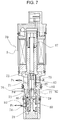
- a displacement control valve there is known one that includes, as shown in FIG. 7 , second communicating passages 73 and a valve hole 77 that communicate a discharge chamber and a control chamber, a second valve chest 82 formed at an intermediate point in a discharge-side passage, third communicating passages 71 and a circulation groove 72 that communicate a suction chamber and the control chamber, a third valve chest 83 formed at an intermediate point in a suction-side passage, a valve element 81 formed such that a second valve section 76 that is disposed in the second valve chest 82 to open and close the second communicating passages 73 and the valve hole 77 and a third valve section 75 that is disposed in the third valve chest 83 to open and close the third communicating passages 71 and the circulation groove 72 reciprocate in an integrated manner while performing opening and closing operation in opposite directions, a first valve chest (displacement chamber) 84 formed close to the control chamber, a pressure-sensitive element (bellows) 78 that is disposed in the first valve chest and exerts a bias
- a displacement control valve 70 is configured to be able to adjust the pressure in the control chamber (control chamber pressure) Pc by communicating the discharge chamber and the control chamber when there arises a need to change the control chamber pressure during displacement control, without having to provide a clutch mechanism to the variable displacement compressor.
- the displacement control valve 70 is also configured to open the suction-side passage by disengaging the first valve section (opening valve connection portion) 79 from the valve seat element (engaging portion) 80 and thereby communicating the suction chamber and the control chamber when the control chamber pressure Pc increases in the variable displacement compressor in a stopped state.
- the above conventional art provides an auxiliary communicating passage 85 in the valve seat element (engaging portion) 80 to enable communication from the displacement chamber 84 through the auxiliary communicating passage 85 and an intermediate communicating passage 86 to the third communicating passages 71 under a suction pressure (see an arrow).
- this configuration enables the vaporization of the refrigerant liquid in the control chamber at 1/10 to 1/15 the speed of a displacement control valve without the auxiliary communicating passage 85 , to bring the compressor into cooling operation.
- FIG. 7 is a state where a current is flowing through the solenoid unit S.
- an opening spring means 87 brings the third valve section 75 into a closed state, which is not shown.
- the second valve section 76 is in an open state.
- the first valve section 79 opens under the suction pressure Ps and the control pressure Pc.
- the first valve section 79 and the valve seat surface of the valve seat element 80 are configured such that they cannot open widely for functional reasons.
- the refrigerant liquid in the control chamber is vaporized, and the fluid at the control pressure Pc flows through first communicating passages 74 into the first valve chest 84 .
- the control pressure Pc and the suction pressure Ps are high, and thus the pressure-sensitive element (bellows) 78 contracts, opening a space between the first valve section 79 and the valve seat surface of the valve seat element 80 .
- the vaporization of the refrigerant liquid in the control chamber is accelerated only in small quantities.
- the provision of the auxiliary communicating passage 85 communicating with the intermediate communicating passage 86 allows the refrigerant liquid in the control chamber to be vaporized rapidly.
- the refrigerant gas flows from the control chamber into the suction chamber even when the space between the first valve section 79 and the valve seat surface of the valve seat element 80 is in a closed state and the flow of the fluid through the auxiliary communicating passage 85 is unnecessary, for example, during the control of the variable displacement compressor, thus resulting in a reduction in the operating efficiency of the variable displacement compressor.
- the conventional art is designed as follows: S 2> S 1 L>LS where S 1 is the (fixed) area of the auxiliary communicating passage 85 , S 2 is the maximum opening area of the third valve section 75 , L (stroke from full closing to full opening) is the maximum stroke of the valve element 81 , and LS is the stroke of the valve element 81 in a control area.
- the refrigerant gas defined by the area S 1 of the auxiliary communicating passage 85 flows from the control chamber into the suction chamber in the whole control area, and the flow of the refrigerant gas is restricted only after the valve element 81 exceeds the control area and approaches the maximum stroke.
- the variable displacement compressor cannot avoid a reduction in operating efficiency during control.
- the present invention has been made to solve the above-described problem of the conventional art, and its object is to provide a displacement control valve that is provided with an auxiliary communicating passage to be improved in the function of discharging a liquid refrigerant in a control chamber at the time of startup of a variable displacement compressor, in which an opening area of a third valve section for opening and closing third communicating passages and a circulation groove during the control of the variable displacement compressor is set smaller than or equal to an opening area of the auxiliary communicating passage so that the displacement control valve can achieve a reduction in startup time and an improvement in operating efficiency during control of the variable displacement compressor simultaneously.
- a displacement control valve that controls a flow rate or pressure in a working control chamber according to a degree of opening of a valve unit, including a valve body having a first valve chest that communicates with first communicating passages for passing fluid at control pressure, a second valve chest that has a second valve seat surface for a valve hole communicating with the first valve chest and communicates with second communicating passages for passing fluid at discharge pressure, and a third valve chest that communicates with third communicating passages for passing fluid at suction pressure and has a third valve seat surface, a valve element disposed in the valve body and having an intermediate communicating passage communicating with the first valve chest and the third communicating passages, the valve element having a second valve section that separates from and comes into contact with the second valve seat surface to open and close the valve hole communicating with the first valve chest and the second valve chest, a third valve section that opens and closes opposite to, and in conjunction with, the second valve section and separates from and comes into contact with the third valve seat
- the displacement control valve which is provided with the auxiliary communicating passage to be improved in the function of discharging the liquid refrigerant in the control chamber at the time of startup of the variable displacement compressor, can reduce the minimum area of a Pc-Ps flow path in the control area, and can achieve a reduction in startup time and an improvement in operating efficiency during control of the variable displacement compressor simultaneously.
- a maximum opening area S 2 max between the third valve section and the third valve seat surface with the second valve section in a closed state is set equal to or substantially equal to the area S 1 of the auxiliary communicating passage.
- the minimum area of the Pc-Ps flow path at the time of liquid refrigerant discharge can be made as large as that in the above-described conventional art.
- a third aspect of the present invention in the displacement control valve in the first or second aspect, in the course of travel of the valve element from a closed state of the second valve section to a closed state of the third valve section, production of the opening area S 2 between the third valve section and the third valve seat surface changes from production by a travel direction gap in the travel direction of the valve element to production by a radial gap in a radial direction that is at right angles to the travel direction of the valve element, and the radial gap is set smaller than the area S 1 of the auxiliary communicating passage.
- the minimum area of the Pc-Ps flow path can be decreased rapidly from an early stage (a stage where the stroke of the valve element is small) in the control area, and can be maintained at small values until a late stage (a stage where the stroke of the valve element is large) in the control area.
- operating efficiency can be improved over the entire range of the control area.
- the third valve seat surface is formed in a stepped shape including a large-diameter portion extending on a second valve chest side in the travel direction of the valve element, a valve seat extending continuously from the large-diameter portion in a direction that is at substantially right angles to the travel direction of the valve element, and a small-diameter portion extending continuously from the valve seat toward a proximal end, and the third valve section opposite the third valve seat surface has an opposing surface portion that is opposite the large-diameter portion and is smaller in diameter than the large-diameter portion and larger in diameter than the small-diameter portion, and a contact portion that can be brought into contact with the valve seat.
- the simple configuration can make the minimum area of the Pc-Ps flow path at the time of liquid refrigerant discharge as large as that in the above-described conventional art, and can reduce the minimum area of the Pc-Ps flow path in the control area, thus enabling provision of the displacement control valve that can achieve a reduction in startup time and an improvement in operating efficiency during control of the variable displacement compressor simultaneously.
- the third valve seat surface is formed in a cylindrical shape having an inner-diameter surface portion, an outer-diameter surface portion, and a valve seat extending in a direction that is at right angles to the travel direction of the valve element
- the third valve section opposite the third valve seat surface is formed in a stepped shape including an outer-diameter surface portion larger in diameter than the inner-diameter surface portion, a contact portion that extends continuously from the outer-diameter surface portion of the third valve section in a radially inward direction that is a direction at substantially right angles to the travel direction of the valve element, and can be brought into contact with the valve seat, an inclined portion that extends continuously from the contact portion, is smaller in diameter than the inner-diameter surface portion, and is inclined radially inwardly away from the second valve section, and a step extending continuously from the inclined portion in a radially inward direction that is a
- the simple configuration can make the minimum area of the Pc-Ps flow path at the time of liquid refrigerant discharge as large as that in the above-described conventional art, and can reduce the minimum area of the Pc-Ps flow path in the control area, thus enabling provision of the displacement control valve that can achieve a reduction in startup time and an improvement in operating efficiency during control of the variable displacement compressor simultaneously.
- the present invention achieves the following outstanding effects.
- the opening area S 2 between the third valve section and the third valve seat surface in the control area to control the flow rate or pressure in the working control chamber is set smaller than the area S 1 of the auxiliary communicating passage, so that the displacement control valve, which is provided with the auxiliary communicating passage to be improved in the function of discharging the liquid refrigerant in the control chamber at the time of startup of the variable displacement compressor, can reduce the minimum area of the Pc-Ps flow path in the control area, and can achieve a reduction in startup time and an improvement in operating efficiency during control of the variable displacement compressor simultaneously.
- the maximum opening area S 2 max between the third valve section and the third valve seat surface with the second valve section in the closed state is set equal to or substantially equal to the area S 1 of the auxiliary communicating passage, so that the minimum area of the Pc-Ps flow path at the time of liquid refrigerant discharge can be made as large as that in the above-described conventional art.
- the third valve seat surface is formed in a stepped shape including the large-diameter portion extending on the second valve chest side in the travel direction of the valve element, the valve seat extending continuously from the large-diameter portion in a direction that is at substantially right angles to the travel direction of the valve element, and the small-diameter portion extending continuously from the valve seat toward the proximal end, and the third valve section opposite the third valve seat surface has the opposing surface portion that is opposite the large-diameter portion and is smaller in diameter than the large-diameter portion and larger in diameter than the small-diameter portion, and the contact portion that can be brought into contact with the valve seat, so that the simple configuration can make the minimum area of the Pc-Ps flow path at the time of liquid refrigerant discharge as large as that in the above-described conventional art, and can reduce the minimum area of the Pc-Ps flow path in the control area, thus enabling provision of the displacement
- the third valve seat surface is formed in a cylindrical shape having the inner-diameter surface portion, the outer-diameter surface portion, and the valve seat extending in a direction that is at right angles to the travel direction of the valve element, and the third valve section opposite the third valve seat surface is formed in a stepped shape including the outer-diameter surface portion larger in diameter than the inner-diameter surface portion, the contact portion that extends continuously from the outer-diameter surface portion in a radially inward direction that is a direction at substantially right angles to the travel direction of the valve element, and can be brought into contact with the valve seat, the inclined portion that extends continuously from the contact portion, is smaller in diameter than the inner-diameter surface portion, and is inclined radially inwardly away from the second valve section, and the step extending continuously from the inclined portion in a radially inward direction that is a direction at substantially right angles to the travel direction of the valve element, so that the simple configuration can make the minimum area of the Pc-Ps flow
- FIG. 1 is a front cross-sectional view showing a displacement control valve according to a first embodiment of the present invention.
- FIGS. 2A to 2C are enlarged views of a portion A in FIG. 1 , and are explanatory diagrams for explaining an opening area S 2 between a third valve section and a third valve seat surface in different states.
- FIG. 3 is an explanatory diagram for explaining the relationship between the opening area S 2 between the third valve section and the third valve seat surface and an area S 1 of an auxiliary communicating passage in the displacement control valve according to the first embodiment.
- FIG. 4 is a front cross-sectional view showing a displacement control valve according to a second embodiment of the present invention.
- FIGS. 5A to 5C are enlarged views of a portion A in FIG. 4 , and are explanatory diagrams for explaining an opening area S 2 between a third valve section and a third valve seat surface in different states.
- FIG. 6 is an explanatory diagram for explaining the relationship between an opening area S 2 between the third valve section and the third valve seat surface and an area S 1 of an auxiliary communicating passage in the displacement control valve according to the second embodiment.
- FIG. 7 is a front cross-sectional view showing the displacement control valve in the conventional art.
- FIG. 8 is an explanatory graph diagram for explaining the relationship between an opening area S 2 between the third valve section and the third valve seat surface and an area S 1 of the auxiliary communicating passage in the displacement control valve according to the conventional art.
- reference numeral 1 denotes a displacement control valve.
- the displacement control valve 1 is provided with a valve body 2 forming an outside shape.
- the valve body 2 includes a first valve body 2 A having a through hole provided with functions inside, and a second valve body 2 B integrally fitted to one end of the first valve body 2 A.
- the first valve body 2 A is made of a metal such as brass, iron, aluminum, or stainless, or a synthetic resin material, or the like.
- the second valve body 2 B is formed of a magnetic substance such as iron.
- the second valve body 2 B is provided separately to be different in function from the material of the first valve body 2 A because a solenoid unit 30 is connected to the second valve body 2 B, and the second valve body 2 B must be of a magnetic substance. If this point is considered, the shape shown in FIG. 1 may be changed appropriately.
- a partition adjuster 3 is connected to the first valve body 2 A at the other end of the through hole. The partition adjuster 3 is fitted to close a first valve chest (hereinafter, sometimes referred to as a displacement chamber) 4 of the first valve body 2 A. If screwed in and fixed with a setscrew not shown, the partition adjuster 3 can axially move and adjust the spring force of a compression spring disposed in parallel in a bellows 22 A or the bellows 22 A.
- the displacement chamber 4 is formed on the one-end side. Further, in the through hole, a valve hole 5 having a diameter smaller than the diameter of the displacement chamber 4 is provided consecutively in communication with the displacement chamber 4 . Furthermore, in the compartment of the through hole, a second valve chest 6 larger in diameter than the valve hole 5 is provided in communication with the valve hole 5 . Moreover, in the compartment of the through hole, a third valve chest 7 is provided consecutively in communication with the second valve chest 6 . A second valve seat surface 6 A is formed around the valve hole 5 in the second valve chest 6 .
- Second communicating passages 8 are formed at the second valve chest 6 in the valve body 2 .
- the second communicating passages 8 are configured to communicate with the interior of a discharge chamber of the variable displacement compressor (not shown) so that the displacement control valve 1 allows fluid at a discharge pressure Pd to flow into a control chamber.
- third communicating passages 10 are formed at the third valve chest 7 in the valve body 2 .
- the third communicating passages 10 are configured to communicate with a suction chamber of the variable displacement compressor so that the displacement control valve 1 allows fluid at a suction pressure Ps to flow into and flow out of the suction chamber.
- first communicating passages 9 that allow fluid at the discharge pressure Pd flowing in from the second valve chest 6 to flow out to the control chamber (crank chamber) of the variable displacement compressor are formed at the displacement chamber 4 .
- the first communicating passages 9 , the second communicating passages 8 , and the third communicating passages 10 are, respectively, two to six in number, for example, and are spaced evenly around a peripheral surface of the valve body 2 , extending therethrough.
- an outer peripheral surface of the valve body 2 is formed into a four-step surface.
- the outer peripheral surface is provided with O-ring fitting grooves at three locations in the axial direction. In each fitting groove, an O-ring 46 is fitted to seal a space between the valve body 2 and a fitting hole of a casing (not shown) into which the valve body 2 is fitted.
- a first valve section 21 A that opens and closes with a first valve seat surface 22 C of a valve seat 22 B is provided at one end of the valve element 21 .
- the first valve section 21 A is provided with a first valve section surface 21 A 1 that opens and closes with the first valve seat surface 22 C.
- the opposite end of the first valve section 21 A to the first valve section surface 21 A 1 is integrally fitted in a mounting hole of a second valve section 21 B as a connecting portion.
- An axially extending intermediate communicating passage 26 is formed through the interior of the first valve section 21 A.
- valve element 21 and the first valve section 21 A connected thereto which are fitted to each other on opposite sides of the valve hole 5 of the valve body 2 , are provided separately for the sake of fitting, the two components may be formed integrally as necessary.
- the outer diameter of the connecting portion of the first valve section 21 A is made smaller than the diameter of the valve hole 5 to form a circulation passage extending through the valve hole 5 so that fluid at the discharge pressure Pd can pass between the valve hole 5 and the connecting portion when the second valve section 21 B is open.
- An auxiliary communicating passage 11 extends through a side surface of the first valve section 21 A into the intermediate communicating passage 26 .
- the diameter of the auxiliary communicating passage 11 is made in a range of 0.5 mm to 2.5 mm.
- the diameter of the auxiliary communicating passage 11 is 0.8 mm to 2.0 mm.
- the auxiliary communicating passage 11 may be provided in a side surface of the valve seat 22 B described later.
- a pressure-sensitive element (hereinafter, referred to as a pressure-sensitive device) 22 is provided in the displacement chamber 4 .
- the pressure-sensitive device 22 includes the metal bellows 22 A connected at one end to the partition adjuster 3 in a sealed state and connected at the other end to the valve seat 22 B.
- the bellows 22 A is made of phosphor bronze or the like, and its spring constant is designed to a predetermined value.
- the interior space of the pressure-sensitive device 22 is a vacuum or contains air.
- the pressure-sensitive device 22 is configured such that the pressure in the displacement chamber 4 (e.g. pressure Pc) and the suction pressure Ps act on an effective pressure-receiving area Ab of the bellows 22 A to contract the pressure-sensitive device 22 .
- the dish-shaped valve seat 22 B provided with the first valve seat surface 22 C at an edge peripheral surface is provided at a free end of the pressure-sensitive device 22 .
- the diameter of the auxiliary communicating passage 11 may vary.
- the second valve section 21 B at an intermediate portion of the valve element 21 is disposed in the second valve chest 6 .
- the second valve section 21 B is provided with a second valve section surface 21 B 1 that is joined to the second valve seat surface 6 A.
- the second valve section surface 21 B 1 is configured to have a sealing pressure-receiving area that is equal to or substantially equal to the effective pressure-receiving area of the pressure-sensitive device 22 .
- a third valve section 21 C on the upper side of the valve element 21 is disposed in the third valve chest 7 .
- the third valve section 21 C opens and closes with a third valve seat surface 31 A formed at a lower end surface of a fixed iron core 31 .
- the intermediate communicating passage 26 extends from the first valve chest 4 to the third valve chest 7 .
- the control fluid Pc can flow out from the first valve chest 4 into the third communicating passages 10 .
- a connecting portion 25 A provided at a lower end portion of a solenoid rod 25 is fitted into a fitting hole 21 D of the valve element 21 .
- the valve element 21 is provided with, for example, four evenly-spaced circulation holes 21 E located below the fitting hole 21 D in the third valve chest 7 . Through the circulation holes 21 E, the third valve chest 7 communicates with the intermediate communicating passage 26 .
- the third valve chest 7 has a surface with a diameter slightly larger than that of the outer shape of the valve element 21 to facilitate flowing of fluid at the suction pressure Ps from the third communicating passages 10 into the third valve chest 7 .
- the above-described configuration of a lower part in FIG. 1 including the valve body 2 , the valve element 21 , and the pressure-sensitive device 22 constitutes a valve unit.
- the other end portion of the solenoid rod 25 opposite the connecting portion 25 A is fitted into a fitting hole 32 A of a plunger 32 for connection.
- the fixed iron core 31 fixed to the first valve body 2 A is provided between the valve element 21 and the plunger 32 .
- the solenoid rod 25 is fitted movably along an inner peripheral surface 31 B of the fixed iron core 31 .
- a spring seat chamber 31 C is formed in the fixed iron core 31 on the side of the plunger 32 .
- Spring means (hereinafter, also referred to as resilient means) 28 for bringing the first valve section 21 A and the second valve section 21 B from a closed state into an open state is disposed in the spring seat chamber 31 C. That is, the spring means 28 springs to separate the plunger 32 from the fixed iron core 31 .
- An attraction surface 31 D of the fixed iron core 31 and a joint surface 32 B of the plunger 32 form opposing tapered surfaces, providing a gap between the opposing surfaces to enable attraction. The separation and contact between the attraction surface 31 D of the fixed iron core 31 and the joint surface 32 B of the plunger 32 depend on the strength of a current flowing through an electromagnetic coil 35 .
- a solenoid case 33 is fixed to a step on the one-end side of the second valve body 2 B.
- the electromagnetic coil 35 is disposed.
- the solenoid unit 30 presents the above overall configuration.
- the electromagnetic coil 35 provided in the solenoid unit 30 is controlled by a control computer (not shown).
- a plunger case 34 is fitted to the fixed iron core 31 .
- the plunger 32 is slidably fitted therein.
- the plunger case 34 is fitted at one end in a fitting hole of the second valve body 2 B, and is fixed at the other end in a fitting hole in an end portion of the solenoid case 33 .
- the above configuration constitutes the solenoid unit 30 .
- a thick curved line of an arrow from one of the first communicating passages 9 to one of the third communicating passages 10 indicates a Pc-Ps flow path.
- the third valve seat surface 31 A is formed in a stepped shape including a large-diameter portion 31 Aa extending on the side of the second valve chest 6 in a travel direction of the valve element 21 , a valve seat 31 Ab that extends continuously from the large-diameter portion 31 Aa in a direction at substantially right angles to the travel direction of the valve element 21 , and a small-diameter portion 31 Ac that extends continuously from the valve seat 31 Ab toward a proximal end of the fixed iron core 31 .
- the third valve section 21 C opposite the third valve seat surface 31 A has an opposing surface portion 21 Ca that is opposite the large-diameter portion 31 Aa of the third valve seat surface 31 A and is smaller in diameter than the large-diameter portion 31 Aa and larger in diameter than the small-diameter portion 31 Ac of the third valve seat surface 31 A, and a contact portion 21 Cb that can be brought into contact with the valve seat 31 Ab.
- the distance L between the contact portion 21 Cb of the third valve section 21 C and the valve seat 31 Ab of the third valve seat surface 31 A represents the stroke of the valve element 21 .
- a travel direction gap Sv between the contact portion 21 Cb of the third valve section 21 C and a distal end 31 Ad of the third valve seat surface 31 A produces the maximum opening area S 2 max.
- the position of the distal end 31 Ad of the third valve seat surface 31 A is set such that the maximum opening area S 2 max is equal to or substantially equal to an area S 1 of the auxiliary communicating passage 11 .
- the travel direction gap Sv changes rapidly with the travel of the valve element.
- a thick curved line of an arrow indicates the Pc-Ps flow path.
- the production of the opening area S 2 between the third valve section 21 C and the third valve seat surface 31 A changes from production by the travel direction gap Sv in the travel direction of the valve element 21 to production by a radial gap Sd in a radial direction that is at right angles to the travel direction of the valve element 21 .
- the radial gap Sd is set to a value smaller than the area S 1 of the auxiliary communicating passage 11 , for example, 10% to 30% of S 1 .
- the radial gap Sd has a substantially fixed value, irrespective of the travel of the valve element 21 .
- the horizontal axis represents the stroke of the valve element 21
- the vertical axis the opening area.
- the left end in FIG. 3 indicates the time of liquid refrigerant discharge, that is, a state where the second valve section 21 B is fully closed (the third valve section 21 C is fully open).
- the right end indicates a state where the second valve section 21 B is fully open (the third valve section 21 C is fully closed).
- a range from the left end to a vertical line formed of a broken line in a substantially midpoint position on the horizontal axis represents the control area.
- a horizontal line formed of a broken line in a substantially midpoint position on the vertical axis represents the area S 1 of the auxiliary communicating passage 11 .
- the opening area S 2 between the third valve section 21 C and the third valve seat surface 31 A in the control area is set smaller than the (fixed) area S 1 of the auxiliary communicating passage 11 , the minimum area of the Pc-Ps flow path is defined by the opening area S 2 between the third valve section 21 C and the third valve seat surface 31 A.
- the opening area S 2 between the third valve section 21 C and the third valve seat surface 31 A in the control area is shown by a solid line.
- the travel direction gap Sv produces the maximum opening area S 2 max, and the maximum opening area S 2 max is set equal to or substantially equal to the area S 1 of the auxiliary communicating passage 11 .
- the opening area S 2 is rapidly decreased from the area S 1 of the auxiliary communicating passage 11 . This is because the opening area S 2 is produced by the travel direction gap Sv shown in FIG. 2A , and the travel direction gap Sv is rapidly decreased with the travel of the valve element 21 .
- the opening area S 2 has a value smaller than the area S 1 of the auxiliary communicating passage 11 since the production thereof changes from the production by the travel direction gap Sv in the travel direction of the valve element 21 to the production by the radial gap Sd in the radial direction that is at right angles to the travel direction of the valve element 21 in the course of travel of the valve element 21 from the closed state of the second valve section 21 B to the closed state of the third valve section 21 C.
- the radial gap Sd is set to a value of about 20% of the area S 1 of the auxiliary communicating passage 11 .
- the displacement control valve according to the first embodiment of the present invention is as described above, and achieves the following outstanding effects.
- the opening area S 2 between the third valve section 21 C and the third valve seat surface 31 A in the control area to control the flow rate or pressure in the working control chamber is set smaller than the area S 1 of the auxiliary communicating passage 11 , so that the displacement control valve, which is provided with the auxiliary communicating passage to be improved in the function of discharging the liquid refrigerant in the control chamber at the time of startup of the variable displacement compressor, can reduce the minimum area of the Pc-Ps flow path in the control area, and can thus achieve a reduction in startup time and an improvement in operating efficiency during control of the variable displacement compressor simultaneously.
- the maximum opening area S 2 max between the third valve section 21 C and the third valve seat surface 31 A when the second valve section 21 B is in the closed state is set equal to or substantially equal to the area S 1 of the auxiliary communicating passage 11 , so that the minimum area of the Pc-Ps flow path at the time of liquid refrigerant discharge can be made as large as that in the above-described conventional art.
- the production of the opening area S 2 between the third valve section 21 C and the third valve seat surface 31 A changes from the production by the travel direction gap Sv in the travel direction of the valve element 21 to the production by the radial gap Sd in the radial direction that is at right angles to the travel direction of the valve element 21 , and the radial gap Sd is set smaller than the area S 1 of the auxiliary communicating passage 11 , so that the minimum area of the Pc-Ps flow path can be decreased rapidly from an early stage (a stage where the stroke of the valve element 21 is small) in the control area, and can be maintained at small values until a late stage (a stage where the stroke of the valve element 21 is large) in the control area.
- the third valve seat surface 31 A is formed in a stepped shape including the large-diameter portion 31 Aa extending on the side of the second valve chest 6 in the travel direction of the valve element 21 , the valve seat 31 Ab extending continuously from the large-diameter portion 31 Aa in a direction that is at substantially right angles to the travel direction of the valve element 21 , and the small-diameter portion 31 Ac extending continuously from the valve seat 31 Ab toward the proximal end, and the third valve section 21 C opposite the third valve seat surface 31 A has the opposing surface portion 21 Ca that is opposite the large-diameter portion 31 Aa and is smaller in diameter than the large-diameter portion 31 Aa and larger in diameter than the small-diameter portion 31 Ac, and the contact portion 21 Cb that can be brought into contact with the valve seat 31 Ab, so that the simple configuration can make the minimum area of the Pc-Ps flow path at the time of liquid refrigerant discharge
- the displacement control valve according to the second embodiment includes a third valve section 41 C and a third valve seat surface 51 A that are different in shape from the third valve section 21 C and the third valve seat surface 31 A of the displacement control valve according to the first embodiment, but is identical to that of the first embodiment in the other basic configuration.
- the same reference numerals and letters are assigned to the same members without duplicated explanation.
- the third valve seat surface 51 A has a cylindrical shape including an inner-diameter surface portion 51 Aa, an outer-diameter surface portion 51 Ab, and a valve seat 51 Ac extending in a direction that is at right angles to the travel direction of the valve element 21 .
- the third valve section 41 C opposite the third valve seat surface 51 A is formed in a stepped shape including an outer-diameter surface portion 41 Ca larger in diameter than the inner-diameter surface portion 51 Aa of the third valve seat surface 51 A, a contact portion 41 Cb extending continuously from the outer-diameter surface portion 41 Ca in a radially inward direction that is a direction at substantially right angles to the travel direction of the valve element 21 , and can be brought into contact with the valve seat 51 Ac, an inclined portion 41 Cc that extends continuously from the contact portion 41 Cb, is smaller in diameter than the inner-diameter surface portion 51 Aa of the third valve seat surface 51 A, and is inclined radially inwardly away from the second valve section 21 B, and a step 41 Cd extending continuously from the inclined portion 41 Cc in an radially inward direction that is a direction at substantially right angles to the travel direction of the valve element 21 .
- the distance L between the contact portion 41 Cb of the third valve section 41 C and the valve seat 51 Ac of the third valve seat surface 51 A represents the stroke of the valve element 21 .
- the travel direction gap Sv between the step 41 Cd of the third valve section 41 C and the valve seat 51 Ac of the third valve seat surface 51 A produces the maximum opening area S 2 max.
- the position of the step 41 Cd of the third valve section 41 C is set such that the maximum opening area S 2 max is equal to or substantially equal to the area S 1 of the auxiliary communicating passage 11 .
- the travel direction gap Sv changes rapidly with the travel of the valve element.
- a thick curved line of an arrow indicates the Pc-Ps flow path.
- the production of the opening area S 2 between the third valve section 41 C and the third valve seat surface 51 A changes from production by the travel direction gap Sv in the travel direction of the valve element 21 to production by a radial gap Sd in a radial direction that is at right angles to the travel direction of the valve element 21 .
- the inclined portion 41 Cc is included, and thus the radial gap Sd changes with the travel of the valve element.
- the radial gap Sd is set smaller than the area S 1 of the auxiliary communicating passage 11 , for example, in a range of 10% to 30% of S 1 .
- An inclination angle ⁇ of the inclined portion 41 Cc is set such that the radial gap Sd gradually decreases with the upward travel of the valve element 21 .
- the inclination angle ⁇ is preferably set in a range of 60° to 90°.
- the second embodiment has the same characteristics as the first embodiment, and when the inclination angle ⁇ is 0°, the second embodiment has the same characteristics as the above-described conventional art. In the case of FIG. 5 , the inclination angle ⁇ is about 80°.
- the horizontal axis represents the stroke of the valve element 21
- the vertical axis the opening area.
- the left end in FIG. 6 indicates the time of liquid refrigerant discharge, that is, a state where the second valve section 21 B is fully closed (the third valve section 41 C is fully open).
- the right end indicates a state where the second valve section 21 B is fully open (the third valve section 41 C is fully closed).
- a range from the left end to a vertical line formed of a broken line in a substantially midpoint position on the horizontal axis represents the control area.
- a horizontal line formed of a broken line in a substantially midpoint position on the vertical axis represents the area S 1 of the auxiliary communicating passage 11 .
- the opening area S 2 between the third valve section 41 C and the third valve seat surface 51 A in the control area is set smaller than the (fixed) area S 1 of the auxiliary communicating passage 11 , the minimum area of the Pc-Ps flow path is defined by the opening area S 2 between the third valve section 41 C and the third valve seat surface 51 A.
- the opening area S 2 between the third valve section 41 C and the third valve seat surface 51 A in the control area is shown by a solid line.
- the travel direction gap Sv produces the maximum opening area S 2 max, and the maximum opening area S 2 max is set equal to or substantially equal to the area S 1 of the auxiliary communicating passage 11 .
- the opening area S 2 is rapidly decreased from the area S 1 of the auxiliary communicating passage 11 . This rapid decrease of the opening area S 2 is because the travel direction gap Sv shown in FIG. 5A is decreased rapidly with the travel of the valve element 21 .
- the opening area S 2 is gradually decreased since the production thereof changes from the production by the travel direction gap Sv in the travel direction of the valve element 21 to the production by the radial gap Sd in the radial direction that is at right angles to the travel direction of the valve element 21 in the course of travel of the valve element 21 from the closed state of the second valve section 21 B to the closed state of the third valve section 41 C, and in a late stage (a stage where the stroke of the valve element 21 is large) in the control area, has a value smaller than the area S 1 of the auxiliary communicating passage 11 .
- the radial gap Sd is set in a range of 40% to 60% of the area S 1 of the auxiliary communicating passage 11 .
- the displacement control valve according to the second embodiment of the present invention has the above configuration, and achieves the following outstanding effects.
- the opening area S 2 between the third valve section 41 C and the third valve seat surface 51 A in the control area to control the flow rate or pressure in the working control chamber is set smaller than the area S 1 of the auxiliary communicating passage 11 , so that the displacement control valve, which is provided with the auxiliary communicating passage to be improved in the function of discharging the liquid refrigerant in the control chamber at the time of startup of the variable displacement compressor, can reduce the minimum area of the Pc-Ps flow path in the control area, and can achieve a reduction in startup time and an improvement in operating efficiency during control of the variable displacement compressor simultaneously.
- the maximum opening area S 2 max between the third valve section 41 C and the third valve seat surface 51 A when the second valve section 21 B is in the closed state is set equal to or substantially equal to the area S 1 of the auxiliary communicating passage 11 , so that the minimum area of the Pc-Ps flow path at the time of liquid refrigerant discharge can be made as large as that in the above-described conventional art.
- the production of the opening area S 2 between the third valve section 41 C and the third valve seat surface 51 A changes from the production by the travel direction gap Sv in the travel direction of the valve element 21 to the production by the radial gap Sd in the radial direction that is at right angles to the travel direction of the valve element 21 , and the radial gap Sd is set smaller than the area S 1 of the auxiliary communicating passage 11 , so that the minimum area of the Pc-Ps flow path can be decreased rapidly from an early stage (a stage where the stroke of the valve element 21 is small) in the control area, and can be maintained at small values until a late stage (a stage where the stroke of the valve element 21 is large) in the control area.
- the third valve seat surface 51 A is formed in a cylindrical shape having the inner-diameter surface portion 51 Aa, the outer-diameter surface portion 51 Ab, and the valve seat 51 Ac extending in a direction that is at right angles to the travel direction of the valve element 21 , and the third valve section 41 C opposite the third valve seat surface 51 A is formed in a stepped shape including the outer-diameter surface portion 41 Ca larger in diameter than the inner-diameter surface portion 51 Aa, the contact portion 41 Cb that extends continuously from the outer-diameter surface portion 41 Ca in a radially inward direction that is a direction at substantially right angles to the travel direction of the valve element 21 , and can be brought into contact with the valve seat 51 Ac, the inclined portion 41 Cc that extends continuously from the contact portion 41 Cb, is smaller in diameter than the inner-diameter surface portion 51 Aa, and is inclined radially inwardly away from the second valve section 21 B
Landscapes
- Engineering & Computer Science (AREA)
- General Engineering & Computer Science (AREA)
- Mechanical Engineering (AREA)
- Compressors, Vaccum Pumps And Other Relevant Systems (AREA)
- Multiple-Way Valves (AREA)
- Control Of Positive-Displacement Pumps (AREA)
Applications Claiming Priority (3)
| Application Number | Priority Date | Filing Date | Title |
|---|---|---|---|
| JP2016054050 | 2016-03-17 | ||
| JP2016-054050 | 2016-03-17 | ||
| PCT/JP2017/009642 WO2017159553A1 (ja) | 2016-03-17 | 2017-03-10 | 容量制御弁 |
Publications (2)
| Publication Number | Publication Date |
|---|---|
| US20190078562A1 US20190078562A1 (en) | 2019-03-14 |
| US10690125B2 true US10690125B2 (en) | 2020-06-23 |
Family
ID=59851441
Family Applications (1)
| Application Number | Title | Priority Date | Filing Date |
|---|---|---|---|
| US16/085,428 Active 2037-04-06 US10690125B2 (en) | 2016-03-17 | 2017-03-10 | Displacement control valve |
Country Status (5)
| Country | Link |
|---|---|
| US (1) | US10690125B2 (ja) |
| EP (1) | EP3431760B1 (ja) |
| JP (1) | JP6810131B2 (ja) |
| CN (1) | CN108779768B (ja) |
| WO (1) | WO2017159553A1 (ja) |
Cited By (9)
| Publication number | Priority date | Publication date | Assignee | Title |
|---|---|---|---|---|
| US11454227B2 (en) | 2018-01-22 | 2022-09-27 | Eagle Industry Co., Ltd. | Capacity control valve |
| US11512786B2 (en) | 2017-11-30 | 2022-11-29 | Eagle Industry Co., Ltd. | Capacity control valve and control method for capacity control valve |
| US11519399B2 (en) | 2017-12-08 | 2022-12-06 | Eagle Industry Co., Ltd. | Capacity control valve and method for controlling same |
| US11542929B2 (en) | 2017-12-14 | 2023-01-03 | Eagle Industry Co., Ltd. | Capacity control valve and method for controlling capacity control valve |
| US11542930B2 (en) * | 2017-02-18 | 2023-01-03 | Eagle Industry Co., Ltd. | Capacity control valve |
| US11542931B2 (en) | 2017-11-15 | 2023-01-03 | Eagle Industry Co., Ltd. | Capacity control valve and capacity control valve control method |
| US11603832B2 (en) | 2017-01-26 | 2023-03-14 | Eagle Industry Co., Ltd. | Capacity control valve having a throttle valve portion with a communication hole |
| US11635152B2 (en) | 2018-11-26 | 2023-04-25 | Eagle Industry Co., Ltd. | Capacity control valve |
| US12060870B2 (en) | 2020-08-24 | 2024-08-13 | Eagle Industry Co., Ltd. | Valve |
Families Citing this family (25)
| Publication number | Priority date | Publication date | Assignee | Title |
|---|---|---|---|---|
| WO2018043186A1 (ja) * | 2016-08-29 | 2018-03-08 | イーグル工業株式会社 | 容量制御弁 |
| CN107975470A (zh) * | 2017-11-27 | 2018-05-01 | 山西中航锦恒科技有限公司 | 一种内部带节流装置的电动控制阀 |
| CN111684156B (zh) | 2018-01-26 | 2022-03-29 | 伊格尔工业股份有限公司 | 容量控制阀 |
| CN111712638B (zh) | 2018-02-15 | 2022-05-03 | 伊格尔工业股份有限公司 | 容量控制阀 |
| WO2019159998A1 (ja) | 2018-02-15 | 2019-08-22 | イーグル工業株式会社 | 容量制御弁 |
| JP7139084B2 (ja) * | 2018-02-27 | 2022-09-20 | イーグル工業株式会社 | 容量制御弁 |
| US11225962B2 (en) | 2018-05-23 | 2022-01-18 | Eagle Industry Co., Ltd. | Capacity control valve |
| WO2020013156A1 (ja) | 2018-07-12 | 2020-01-16 | イーグル工業株式会社 | 容量制御弁 |
| CN112384695B (zh) | 2018-07-12 | 2022-12-06 | 伊格尔工业股份有限公司 | 容量控制阀 |
| US11555489B2 (en) | 2018-07-12 | 2023-01-17 | Eagle Industry Co., Ltd. | Capacity control valve |
| CN112424473B (zh) | 2018-07-13 | 2023-02-28 | 伊格尔工业股份有限公司 | 容量控制阀 |
| EP3835576B1 (en) | 2018-08-08 | 2024-03-27 | Eagle Industry Co., Ltd. | Capacity control valve |
| CN112513460B (zh) | 2018-08-08 | 2023-04-28 | 伊格尔工业股份有限公司 | 容量控制阀 |
| EP3835578B1 (en) | 2018-08-08 | 2023-12-06 | Eagle Industry Co., Ltd. | Capacity control valve |
| US11378194B2 (en) | 2018-11-07 | 2022-07-05 | Eagle Industry Co., Ltd. | Capacity control valve |
| US11473684B2 (en) | 2018-12-04 | 2022-10-18 | Eagle Industry Co., Ltd. | Capacity control valve |
| KR102603184B1 (ko) | 2018-12-04 | 2023-11-16 | 이구루코교 가부시기가이샤 | 용량 제어 밸브 |
| EP3933197A4 (en) | 2019-03-01 | 2022-11-30 | Eagle Industry Co., Ltd. | CAPACITY CONTROL VALVE |
| JP7438643B2 (ja) | 2019-04-03 | 2024-02-27 | イーグル工業株式会社 | 容量制御弁 |
| WO2020204131A1 (ja) | 2019-04-03 | 2020-10-08 | イーグル工業株式会社 | 容量制御弁 |
| WO2021010259A1 (ja) | 2019-07-12 | 2021-01-21 | イーグル工業株式会社 | 容量制御弁 |
| JP7337453B2 (ja) * | 2019-07-17 | 2023-09-04 | イーグル工業株式会社 | 容量制御弁 |
| KR20220159471A (ko) | 2020-04-23 | 2022-12-02 | 이구루코교 가부시기가이샤 | 용량 제어 밸브 |
| US12025237B2 (en) * | 2020-05-25 | 2024-07-02 | Eagle Industry Co., Ltd. | Capacity control valve |
| US11300219B2 (en) * | 2020-07-28 | 2022-04-12 | Mahle International Gmbh | Variable-capacity compressor control valve |
Citations (5)
| Publication number | Priority date | Publication date | Assignee | Title |
|---|---|---|---|---|
| US20030145615A1 (en) * | 2002-02-04 | 2003-08-07 | Eagle Industry Co. Ltd. | Capacity control valve |
| WO2007119380A1 (ja) | 2006-03-15 | 2007-10-25 | Eagle Industry Co., Ltd. | 容量制御弁 |
| JP2008031962A (ja) | 2006-07-31 | 2008-02-14 | Calsonic Kansei Corp | 可変容量圧縮機 |
| WO2011114841A1 (ja) | 2010-03-16 | 2011-09-22 | イーグル工業株式会社 | 容量制御弁 |
| US20160290326A1 (en) * | 2015-04-02 | 2016-10-06 | Tgk Co., Ltd. | Control valve for variable displacement compressor |
Family Cites Families (4)
| Publication number | Priority date | Publication date | Assignee | Title |
|---|---|---|---|---|
| JP3634499B2 (ja) * | 1996-04-30 | 2005-03-30 | 株式会社豊田自動織機 | 電磁式制御弁 |
| WO2004065789A1 (ja) * | 2003-01-22 | 2004-08-05 | Zexel Valeo Climate Control Corporation | 可変容量圧縮機の制御弁 |
| US8021124B2 (en) * | 2005-02-24 | 2011-09-20 | Eagle Industry Co., Ltd. | Capacity control valve |
| WO2006129753A1 (ja) * | 2005-06-03 | 2006-12-07 | Eagle Industry Co., Ltd. | 容量制御弁 |
-
2017
- 2017-03-10 EP EP17766553.6A patent/EP3431760B1/en active Active
- 2017-03-10 WO PCT/JP2017/009642 patent/WO2017159553A1/ja active Application Filing
- 2017-03-10 JP JP2018505887A patent/JP6810131B2/ja active Active
- 2017-03-10 CN CN201780017190.XA patent/CN108779768B/zh active Active
- 2017-03-10 US US16/085,428 patent/US10690125B2/en active Active
Patent Citations (9)
| Publication number | Priority date | Publication date | Assignee | Title |
|---|---|---|---|---|
| US20030145615A1 (en) * | 2002-02-04 | 2003-08-07 | Eagle Industry Co. Ltd. | Capacity control valve |
| WO2007119380A1 (ja) | 2006-03-15 | 2007-10-25 | Eagle Industry Co., Ltd. | 容量制御弁 |
| US20090183786A1 (en) | 2006-03-15 | 2009-07-23 | Eagle Industry Co., Ltd. | Displacement Control Valve |
| US8079827B2 (en) * | 2006-03-15 | 2011-12-20 | Eagle Industry Co., Ltd. | Displacement control valve |
| JP5167121B2 (ja) | 2006-03-15 | 2013-03-21 | イーグル工業株式会社 | 容量制御弁 |
| JP2008031962A (ja) | 2006-07-31 | 2008-02-14 | Calsonic Kansei Corp | 可変容量圧縮機 |
| WO2011114841A1 (ja) | 2010-03-16 | 2011-09-22 | イーグル工業株式会社 | 容量制御弁 |
| US20120198992A1 (en) | 2010-03-16 | 2012-08-09 | Masayuki Futakuchi | Volume control valve |
| US20160290326A1 (en) * | 2015-04-02 | 2016-10-06 | Tgk Co., Ltd. | Control valve for variable displacement compressor |
Cited By (10)
| Publication number | Priority date | Publication date | Assignee | Title |
|---|---|---|---|---|
| US11603832B2 (en) | 2017-01-26 | 2023-03-14 | Eagle Industry Co., Ltd. | Capacity control valve having a throttle valve portion with a communication hole |
| US11542930B2 (en) * | 2017-02-18 | 2023-01-03 | Eagle Industry Co., Ltd. | Capacity control valve |
| US11542931B2 (en) | 2017-11-15 | 2023-01-03 | Eagle Industry Co., Ltd. | Capacity control valve and capacity control valve control method |
| US11795928B2 (en) | 2017-11-15 | 2023-10-24 | Eagle Industry Co., Ltd. | Capacity control valve and capacity control valve control method |
| US11512786B2 (en) | 2017-11-30 | 2022-11-29 | Eagle Industry Co., Ltd. | Capacity control valve and control method for capacity control valve |
| US11519399B2 (en) | 2017-12-08 | 2022-12-06 | Eagle Industry Co., Ltd. | Capacity control valve and method for controlling same |
| US11542929B2 (en) | 2017-12-14 | 2023-01-03 | Eagle Industry Co., Ltd. | Capacity control valve and method for controlling capacity control valve |
| US11454227B2 (en) | 2018-01-22 | 2022-09-27 | Eagle Industry Co., Ltd. | Capacity control valve |
| US11635152B2 (en) | 2018-11-26 | 2023-04-25 | Eagle Industry Co., Ltd. | Capacity control valve |
| US12060870B2 (en) | 2020-08-24 | 2024-08-13 | Eagle Industry Co., Ltd. | Valve |
Also Published As
| Publication number | Publication date |
|---|---|
| EP3431760A4 (en) | 2019-11-13 |
| JP6810131B2 (ja) | 2021-01-06 |
| JPWO2017159553A1 (ja) | 2019-02-21 |
| CN108779768A (zh) | 2018-11-09 |
| EP3431760B1 (en) | 2020-09-23 |
| WO2017159553A1 (ja) | 2017-09-21 |
| US20190078562A1 (en) | 2019-03-14 |
| CN108779768B (zh) | 2020-05-12 |
| EP3431760A1 (en) | 2019-01-23 |
Similar Documents
| Publication | Publication Date | Title |
|---|---|---|
| US10690125B2 (en) | Displacement control valve | |
| US10781804B2 (en) | Displacement control valve | |
| US11512786B2 (en) | Capacity control valve and control method for capacity control valve | |
| US11603832B2 (en) | Capacity control valve having a throttle valve portion with a communication hole | |
| US11085431B2 (en) | Displacement control valve | |
| US9777863B2 (en) | Capacity control valve | |
| KR101689241B1 (ko) | 용량 제어 밸브 | |
| WO2019117225A1 (ja) | 容量制御弁及び容量制御弁の制御方法 | |
| WO2019131694A1 (ja) | 容量制御弁及び容量制御弁の制御方法 | |
| WO2019009264A1 (ja) | 容量制御弁 | |
| US20170211561A1 (en) | Variable displacement swash plate type compressor | |
| JP7146262B2 (ja) | 制御弁 | |
| US20210363980A1 (en) | Capacity control valve | |
| US11542930B2 (en) | Capacity control valve | |
| WO2019097841A1 (ja) | クラッチ付き斜板式可変容量圧縮機の容量制御弁 | |
| EP3438513A1 (en) | Control valve | |
| US11401922B2 (en) | Displacement control valve | |
| WO2019142930A1 (ja) | 容量制御弁及び容量制御弁の制御方法 | |
| KR101622946B1 (ko) | 가변 용량 압축기용 제어밸브 |
Legal Events
| Date | Code | Title | Description |
|---|---|---|---|
| AS | Assignment |
Owner name: EAGLE INDUSTRY CO., LTD., JAPAN Free format text: ASSIGNMENT OF ASSIGNORS INTEREST;ASSIGNORS:HAYAMA, MASAHIRO;HIGASHIDOZONO, HIDEKI;FUKUDOME, KOHEI;AND OTHERS;REEL/FRAME:046881/0619 Effective date: 20180907 |
|
| FEPP | Fee payment procedure |
Free format text: ENTITY STATUS SET TO UNDISCOUNTED (ORIGINAL EVENT CODE: BIG.); ENTITY STATUS OF PATENT OWNER: LARGE ENTITY |
|
| STPP | Information on status: patent application and granting procedure in general |
Free format text: DOCKETED NEW CASE - READY FOR EXAMINATION |
|
| STPP | Information on status: patent application and granting procedure in general |
Free format text: NON FINAL ACTION MAILED |
|
| STPP | Information on status: patent application and granting procedure in general |
Free format text: NOTICE OF ALLOWANCE MAILED -- APPLICATION RECEIVED IN OFFICE OF PUBLICATIONS |
|
| STPP | Information on status: patent application and granting procedure in general |
Free format text: PUBLICATIONS -- ISSUE FEE PAYMENT RECEIVED |
|
| STCF | Information on status: patent grant |
Free format text: PATENTED CASE |
|
| MAFP | Maintenance fee payment |
Free format text: PAYMENT OF MAINTENANCE FEE, 4TH YEAR, LARGE ENTITY (ORIGINAL EVENT CODE: M1551); ENTITY STATUS OF PATENT OWNER: LARGE ENTITY Year of fee payment: 4 |