US10656576B2 - Image forming apparatus, image forming system, and image forming method each controlling fixing temperature - Google Patents
Image forming apparatus, image forming system, and image forming method each controlling fixing temperature Download PDFInfo
- Publication number
- US10656576B2 US10656576B2 US16/388,514 US201916388514A US10656576B2 US 10656576 B2 US10656576 B2 US 10656576B2 US 201916388514 A US201916388514 A US 201916388514A US 10656576 B2 US10656576 B2 US 10656576B2
- Authority
- US
- United States
- Prior art keywords
- image
- image forming
- value
- temperature
- areas
- Prior art date
- Legal status (The legal status is an assumption and is not a legal conclusion. Google has not performed a legal analysis and makes no representation as to the accuracy of the status listed.)
- Active
Links
- 238000000034 method Methods 0.000 title claims description 89
- 239000000463 material Substances 0.000 claims abstract description 57
- 238000004458 analytical method Methods 0.000 claims abstract description 32
- 238000006243 chemical reaction Methods 0.000 claims abstract description 30
- 238000004891 communication Methods 0.000 claims description 4
- 238000012545 processing Methods 0.000 description 104
- 239000010408 film Substances 0.000 description 29
- 238000010438 heat treatment Methods 0.000 description 21
- 238000010586 diagram Methods 0.000 description 16
- 238000012546 transfer Methods 0.000 description 15
- 230000000052 comparative effect Effects 0.000 description 11
- 238000011156 evaluation Methods 0.000 description 8
- 238000010191 image analysis Methods 0.000 description 8
- 230000015572 biosynthetic process Effects 0.000 description 6
- 239000000758 substrate Substances 0.000 description 5
- 239000004813 Perfluoroalkoxy alkane Substances 0.000 description 4
- 239000003086 colorant Substances 0.000 description 4
- 239000011521 glass Substances 0.000 description 4
- 229920011301 perfluoro alkoxyl alkane Polymers 0.000 description 4
- 230000008569 process Effects 0.000 description 4
- 239000004812 Fluorinated ethylene propylene Substances 0.000 description 3
- 238000004140 cleaning Methods 0.000 description 3
- 238000007796 conventional method Methods 0.000 description 3
- 229910052751 metal Inorganic materials 0.000 description 3
- 229920009441 perflouroethylene propylene Polymers 0.000 description 3
- 229920001343 polytetrafluoroethylene Polymers 0.000 description 3
- 239000004810 polytetrafluoroethylene Substances 0.000 description 3
- 230000000717 retained effect Effects 0.000 description 3
- OKTJSMMVPCPJKN-UHFFFAOYSA-N Carbon Chemical compound [C] OKTJSMMVPCPJKN-UHFFFAOYSA-N 0.000 description 2
- XEEYBQQBJWHFJM-UHFFFAOYSA-N Iron Chemical compound [Fe] XEEYBQQBJWHFJM-UHFFFAOYSA-N 0.000 description 2
- PXHVJJICTQNCMI-UHFFFAOYSA-N Nickel Chemical compound [Ni] PXHVJJICTQNCMI-UHFFFAOYSA-N 0.000 description 2
- 239000004696 Poly ether ether ketone Substances 0.000 description 2
- 239000004642 Polyimide Substances 0.000 description 2
- 239000004734 Polyphenylene sulfide Substances 0.000 description 2
- 241000519995 Stachys sylvatica Species 0.000 description 2
- 238000005299 abrasion Methods 0.000 description 2
- PNEYBMLMFCGWSK-UHFFFAOYSA-N aluminium oxide Inorganic materials [O-2].[O-2].[O-2].[Al+3].[Al+3] PNEYBMLMFCGWSK-UHFFFAOYSA-N 0.000 description 2
- 229910052799 carbon Inorganic materials 0.000 description 2
- 230000015556 catabolic process Effects 0.000 description 2
- 239000011248 coating agent Substances 0.000 description 2
- 238000000576 coating method Methods 0.000 description 2
- 239000002131 composite material Substances 0.000 description 2
- 239000013078 crystal Substances 0.000 description 2
- 238000006731 degradation reaction Methods 0.000 description 2
- 230000000694 effects Effects 0.000 description 2
- 229920001971 elastomer Polymers 0.000 description 2
- 230000006870 function Effects 0.000 description 2
- 238000005259 measurement Methods 0.000 description 2
- 239000002184 metal Substances 0.000 description 2
- 238000012986 modification Methods 0.000 description 2
- 230000004048 modification Effects 0.000 description 2
- 229920002530 polyetherether ketone Polymers 0.000 description 2
- 229920001721 polyimide Polymers 0.000 description 2
- 229920000642 polymer Polymers 0.000 description 2
- 229920000069 polyphenylene sulfide Polymers 0.000 description 2
- 230000004044 response Effects 0.000 description 2
- 239000004945 silicone rubber Substances 0.000 description 2
- KXGFMDJXCMQABM-UHFFFAOYSA-N 2-methoxy-6-methylphenol Chemical compound [CH]OC1=CC=CC([CH])=C1O KXGFMDJXCMQABM-UHFFFAOYSA-N 0.000 description 1
- 229910000838 Al alloy Inorganic materials 0.000 description 1
- 229910001252 Pd alloy Inorganic materials 0.000 description 1
- BUGBHKTXTAQXES-UHFFFAOYSA-N Selenium Chemical compound [Se] BUGBHKTXTAQXES-UHFFFAOYSA-N 0.000 description 1
- 229910021417 amorphous silicon Inorganic materials 0.000 description 1
- 230000008901 benefit Effects 0.000 description 1
- 239000000919 ceramic Substances 0.000 description 1
- 239000003795 chemical substances by application Substances 0.000 description 1
- 239000011231 conductive filler Substances 0.000 description 1
- 239000004020 conductor Substances 0.000 description 1
- 238000011109 contamination Methods 0.000 description 1
- PMHQVHHXPFUNSP-UHFFFAOYSA-M copper(1+);methylsulfanylmethane;bromide Chemical compound Br[Cu].CSC PMHQVHHXPFUNSP-UHFFFAOYSA-M 0.000 description 1
- 230000007547 defect Effects 0.000 description 1
- 230000003111 delayed effect Effects 0.000 description 1
- 238000001514 detection method Methods 0.000 description 1
- HQQADJVZYDDRJT-UHFFFAOYSA-N ethene;prop-1-ene Chemical group C=C.CC=C HQQADJVZYDDRJT-UHFFFAOYSA-N 0.000 description 1
- 230000002349 favourable effect Effects 0.000 description 1
- 238000005187 foaming Methods 0.000 description 1
- 229910002804 graphite Inorganic materials 0.000 description 1
- 239000010439 graphite Substances 0.000 description 1
- 239000004519 grease Substances 0.000 description 1
- 230000017525 heat dissipation Effects 0.000 description 1
- 238000009413 insulation Methods 0.000 description 1
- 229910052742 iron Inorganic materials 0.000 description 1
- 230000009191 jumping Effects 0.000 description 1
- 239000000314 lubricant Substances 0.000 description 1
- 238000013507 mapping Methods 0.000 description 1
- 229910052759 nickel Inorganic materials 0.000 description 1
- SWELZOZIOHGSPA-UHFFFAOYSA-N palladium silver Chemical compound [Pd].[Ag] SWELZOZIOHGSPA-UHFFFAOYSA-N 0.000 description 1
- 229920001568 phenolic resin Polymers 0.000 description 1
- 239000005011 phenolic resin Substances 0.000 description 1
- -1 polytetrafluoroethylene Polymers 0.000 description 1
- 229920005989 resin Polymers 0.000 description 1
- 239000011347 resin Substances 0.000 description 1
- 229920002631 room-temperature vulcanizate silicone Polymers 0.000 description 1
- 229910052711 selenium Inorganic materials 0.000 description 1
- 239000011669 selenium Substances 0.000 description 1
- 229920002379 silicone rubber Polymers 0.000 description 1
- 239000010935 stainless steel Substances 0.000 description 1
- 229910001220 stainless steel Inorganic materials 0.000 description 1
- 238000012360 testing method Methods 0.000 description 1
- 239000010409 thin film Substances 0.000 description 1
- 230000000007 visual effect Effects 0.000 description 1
Images


Classifications
-
- G—PHYSICS
- G03—PHOTOGRAPHY; CINEMATOGRAPHY; ANALOGOUS TECHNIQUES USING WAVES OTHER THAN OPTICAL WAVES; ELECTROGRAPHY; HOLOGRAPHY
- G03G—ELECTROGRAPHY; ELECTROPHOTOGRAPHY; MAGNETOGRAPHY
- G03G15/00—Apparatus for electrographic processes using a charge pattern
- G03G15/20—Apparatus for electrographic processes using a charge pattern for fixing, e.g. by using heat
- G03G15/2003—Apparatus for electrographic processes using a charge pattern for fixing, e.g. by using heat using heat
- G03G15/2014—Apparatus for electrographic processes using a charge pattern for fixing, e.g. by using heat using heat using contact heat
- G03G15/2039—Apparatus for electrographic processes using a charge pattern for fixing, e.g. by using heat using heat using contact heat with means for controlling the fixing temperature
-
- G—PHYSICS
- G03—PHOTOGRAPHY; CINEMATOGRAPHY; ANALOGOUS TECHNIQUES USING WAVES OTHER THAN OPTICAL WAVES; ELECTROGRAPHY; HOLOGRAPHY
- G03G—ELECTROGRAPHY; ELECTROPHOTOGRAPHY; MAGNETOGRAPHY
- G03G2215/00—Apparatus for electrophotographic processes
- G03G2215/20—Details of the fixing device or porcess
- G03G2215/2003—Structural features of the fixing device
- G03G2215/2016—Heating belt
- G03G2215/2035—Heating belt the fixing nip having a stationary belt support member opposing a pressure member
Definitions
- aspects of the present disclosure generally relate to an image forming apparatus using an electrophotographic method.
- Japanese Patent Application Laid-Open No. 2016-4231 discusses a method of controlling a fixing temperature according to the amount of toner calculated based on image data. Specifically, the method divides the entire region of image data into a plurality of areas each with a size of, for example, 32 dots by 32 dots, and controls the fixing temperature based on the amount of toner for an area to which the greatest amount of toner is allocated among all of the areas and the printing ratio of the entire image. In other words, if the greatest amount of toner is large, the method raises the fixing temperature to perform fixing, and, if the greatest amount of toner is small, the method lowers the fixing temperature to perform fixing.
- Such a conventional method can be used to control the fixing temperature according to the printing ratio of an image to be formed.
- the conventional method performs control to analyze the entire region of image data and find an area to which the greatest amount of toner is allocated, and therefore, may need to have a configuration including, for example, a huge memory corresponding to image data and a central processing unit (CPU) which is high in processing speed for performing image analysis.
- CPU central processing unit
- an image forming apparatus includes an image forming unit configured to form an image based on image data, a fixing unit configured to fix the image formed by the image forming unit on a recording material, a conversion unit configured to convert image data into conversion data including a plurality of areas having a first resolution in a main scanning direction perpendicular to a conveyance direction of the recording material, and a second resolution higher than the first resolution in a sub-scanning direction, which is the conveyance direction of the recording material, an analysis unit configured to analyze values related to the areas of the plurality of areas of the conversion data obtained by the conversion unit, and a temperature control unit configured to control a fixing temperature of the fixing unit according to a result of the analysis performed by the analysis unit.
- FIG. 1 is an outline configuration diagram of an image forming apparatus.
- FIG. 2 is a block diagram illustrating, for example, a control unit of the image forming apparatus.
- FIG. 3 is an outline configuration diagram illustrating a fixing device of the film heating type.
- FIG. 4 is a diagram illustrating an example of a case where the fixing temperature is controlled.
- FIG. 5 is a flowchart illustrating a method of controlling the fixing temperature.
- FIGS. 6A and 6B are diagrams illustrating a result of the method of controlling the fixing temperature being performed.
- FIGS. 7A and 7B are diagrams illustrating a result of the method of controlling the fixing temperature being performed.
- FIG. 8 is a diagram illustrating examples of images having various patterns formed on recording materials, including an image 1 to an image 6.
- FIG. 9 is a flowchart illustrating a method of controlling the fixing temperature.
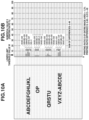
- FIGS. 10A and 10B are diagrams illustrating a result of the method of controlling the fixing temperature being performed.
- FIGS. 11A and 11B are diagrams illustrating a result of the method of controlling the fixing temperature being performed.
- FIG. 12 is a diagram illustrating a text image.
- FIG. 1 is an outline configuration diagram of an image forming apparatus according to a first exemplary embodiment.
- an image forming apparatus for forming a monochroic image is described as an example, the image forming apparatus is not limited to this.
- the first exemplary embodiment can also be applied to an image forming apparatus which forms a color image using the intermediate transfer method, which secondarily transfers, to a recording material, an image primarily transferred from a photosensitive drum to an intermediate transfer belt, and an image forming apparatus which forms a color image using the direct transfer method, which directly transfers an image from a photosensitive drum to a recording material.
- a photosensitive drum 1 serving as a photosensitive member is a member composed by providing a photosensitive material, such as organic photo conductor (OPC), amorphous selenium, or amorphous silicon, on a drum base on a cylinder formed from aluminum alloy or nickel.
- the photosensitive drum 1 is driven to rotate by a motor serving as a drive unit (not illustrated) at a predetermined process speed (circumferential velocity) in the direction of arrow R 1 .
- a charging roller 2 serving as a charging unit uniformly charges the surface of the photosensitive drum 1 to a predetermined polarity and potential. Scanning the charged surface of the photosensitive drum 1 with a laser beam E radiated from a laser scanner 3 serving as an exposure unit forms an electrostatic latent image on the photosensitive drum 1 .
- the laser scanner 3 performs control to determine whether to radiate the laser beam E according to image information. Performing scanning with the laser beam E controlled in this way along the longitudinal direction of the photosensitive drum 1 forms an electrostatic latent image on the photosensitive drum 1 .
- the electrostatic latent image formed on the photosensitive drum 1 is developed with a developer (toner) by a developing device 4 serving as a developing unit, thus being made visible as an image.
- the developing method used for the developing device 4 includes, for example, a jumping developing method, a two-component developing method, and a contact developing method.
- Members for forming an image based on image data in the above-mentioned way can also be referred to as an “image forming unit”.
- An image on the photosensitive drum 1 developed by the developing device 4 is transferred to a recording material P.
- the recording material P is stacked on a paper feed tray 101 , and is fed on a sheet-by-sheet basis by a paper feed roller 102 .
- the fed recording material P is conveyed by a conveyance roller 103 .
- the leading edge of the recording material P being conveyed is detected by a top sensor 104 .
- the timing at which the leading edge of the recording material P arrives at a transfer nip portion T is determined based on the position of the top sensor 104 , the position of the transfer nip portion T, and the conveyance speed of the recording material P.
- the image on the photosensitive drum 1 also moves to the transfer nip portion T according to the timing at which the recording material P arrives at the transfer nip portion T, and is then transferred onto the recording material P in response to a transfer bias being applied to a transfer roller 5 serving as a transfer unit.
- the recording material P having the image transferred thereto is conveyed to a fixing device 6 serving as a fixing unit.
- the recording material P is then heated and pressed while being nipped and conveyed at a fixing nip portion between a heating member 10 and a pressure roller 20 in the fixing device 6 , so that the image is fixed to the surface of the recording material P.
- the recording material P subjected to fixing is discharged by a discharge roller 106 onto a discharge tray 107 , which is formed on the image forming apparatus 100 . Furthermore, whether, for example, paper jam has occurred is monitored by a paper discharge sensor 105 detecting the timing at which the leading edge and trailing edge of the recording material P pass by.
- toner remaining on the photosensitive drum 1 without being transferred to the recording material P is cleaned off by a cleaning blade 71 of a cleaning device 7 serving as a cleaning unit. After such a series of operations is performed, the image forming operation ends.
- FIG. 2 is a block diagram illustrating, for example, a control unit of the image forming apparatus 100 .
- a printer control unit 304 performs control over the image forming apparatus 100 with a controller 301 (first control unit) and an engine control unit 302 (second control unit).
- the controller 301 is connected to a host computer 300 via a controller interface 305 , and thus performs communication therewith.
- the controller 301 performs, for example, bit-mapping of character code and halftoning processing of a gray scale image at an image processing unit 303 based on image data received from the host computer 300 , thus generating image information.
- the controller 301 transmits the generated image information to the engine control unit 302 , which serves as a control unit, via a video interface 310 of the engine control unit 302 .
- the controller 301 and the engine control unit 302 are able to communicate with each other via the video interface 310 .
- the image information includes information for controlling a fixing temperature calculated by the image processing unit 303 . Furthermore, a specific method of calculating information for controlling the fixing temperature is described below in detail.
- An application specific integrated circuit (ASIC) 314 which is an integrated circuit for a specific application, in the engine control unit 302 performs a part of control operations related to image formation, such as light emission timing of the laser scanner 3 .
- a central processing unit (CPU) 311 which is a central arithmetic processing device, in the engine control unit 302 performs a part of control operations related to image formation according to, for example, a printing mode or image size information.
- the CPU 311 stores information in a random access memory (RAM) 313 as needed, uses a program stored in a read-only memory (ROM) 312 or the RAM 313 , and refers to information stored in the ROM 312 or the RAM 313 .
- RAM random access memory
- ROM read-only memory
- the CPU 311 performs control of the fixing temperature in the fixing device 6 at a fixing control unit 320 , control of the paper feed speed and paper feed interval of the paper feed roller 102 at a paper feeding conveyance control unit 330 , and control of the process speed, developing, charging, and transfer at an image forming control unit 340 .
- the controller 301 transmits, for example, a print instruction or a cancel instruction to the engine control unit 302 in response to an instruction issued by the user operating the host computer 300 , thus also performing control of, for example, starting or ending of a printing operation.
- FIG. 3 is an outline configuration diagram illustrating the fixing device 6 of the film heating type.
- the fixing device 6 includes a film unit (heating member) 10 , which performs heating, and a pressure roller 20 , which performs application of pressure.
- the film unit 10 includes a heat-resistant film (fixing film) 13 , which is a heating rotation member serving as a heat-transfer member, a heater 11 , which is a heating member, and a heat-insulating stay holder 12 , which is a heater holding member.
- the pressure roller 20 is located at a position facing the film unit 10 .
- a recording material P having an image “t” formed thereon is nipped and conveyed at a nip portion which is formed by the heater 11 and the pressure roller 20 via the fixing film 13 . With this, heating and application of pressure are performed on the image “t”, so that the image “t” is fixed to the recording material P.
- a thermistor 14 serving as a temperature detection unit is located at a surface of the heater 11 opposite to the sliding surface thereof with the fixing film 13 , so that the heater 11 is controlled by the engine control unit 302 in such a way as to become at a desired temperature.
- the heater 11 includes a resistance heating layer (heating element) 112 on a substrate (insulating substrate) 113 , which is made from alumina or aluminum nitride as a ceramic. Then, the heater 11 is covered with an overcoat glass 111 for the purpose of insulation and abrasion resistance of the resistance heating layer 112 , and is thus configured such that the overcoat glass 111 is in contact with the inner circumferential surface of the fixing film 13 .
- the fixing film 13 is a composite layer film such as that described as follows. First, a thin metallic element tube made from, for example, stainless steel (SUS) or a high-temperature resin made from, for example, polyimide and a thermal conductive filler such as graphite are kneaded. Then, the surface of a base layer into which the kneaded materials are molded in a tubular shape is, directly or via a primer layer, coated with or covered in a tubular form with a releasable layer such as perfluoroalkoxy alkane (PFA), polytetrafluoroethylene (PTFE), or fluorinated ethylene propylene copolymer (FEP), so that a composite layer film is formed.
- the fixing film 13 used in the first exemplary embodiment is a film obtained by coating a base layer polyimide with PFA. The total film thickness thereof is 70 ⁇ m, and the outer circumferential length thereof is 56 mm.
- the fixing film 13 rotates while frictionally sliding on the heater 11 and the heat-insulating stay holder 12 , which are located inside the fixing film 13 , it is necessary to reduce the frictional resistance between each of the heater 11 and the heat-insulating stay holder 12 and the fixing film 13 to a small value. Therefore, a small amount of lubricant such as high-temperature grease is applied onto the surfaces of the heater 11 and the heat-insulating stay holder 12 . This enables the fixing film 13 to smoothly rotate.
- the pressure roller 20 is configured by first forming an elastic layer 22 , which is made by foaming heat-resisting rubber such as insulating silicone rubber or fluorine-contained rubber, on a metal core 21 made from, for example, iron and applying room temperature vulcanizing (RTV) silicone rubber, which has adhesiveness by being subjected to primer treatment, as an adhesion layer onto the elastic layer 22 . Then, the pressure roller 20 is configured by forming a releasable layer 23 which is obtained by covering or coating the elastic layer 22 with a tube in which a conducting agent such as carbon is dispersed in, for example, PFA, PTFE, or FEP.
- the pressure roller 20 used in the first exemplary embodiment is a pressure roller with an outer diameter of 20 mm and a hardness of 48° (Asker-C under a weight of 600 g).
- the pressure roller 20 is pressed by a pressure unit (not illustrated) at 15 Kg ⁇ f from both longitudinal end portions thereof so as to form a nip portion required for heating and fixing. Moreover, the pressure roller 20 is driven to rotate in the direction of an arrow illustrated in FIG. 3 (counterclockwise direction) by a rotation driving unit (not illustrated) from the longitudinal end portion thereof via the metal core 21 . With this, the fixing film 13 is rotated following the pressure roller 20 in the direction of an arrow illustrated in FIG. 3 (clockwise direction) at the outer side of the heat-insulating stay holder 12 .
- the heater 11 is located inside the fixing film 13 , and is configured by forming the resistance heating layer 112 on the substrate 113 and covering the resistance heating layer 112 with the thin-film overcoat glass 111 .
- the overcoat glass 111 is excellent in withstanding voltage and abrasion resistance, and is configured to slide on the fixing film 13 .
- the heater 11 used in the first exemplary embodiment is a heater with a thermal conductivity of 1.0 W/m ⁇ K, a withstanding voltage feature of 2.5 KV or more, and a film thickness of 70 ⁇ m.
- the substrate 113 of the heater 11 used in the first exemplary embodiment is made from alumina.
- the substrate 113 has a dimension of 6.0 mm in width, 260.0 mm in length, and 1.00 mm in thickness, and has a thermal expansion rate of 7.6 ⁇ 10 ⁇ 6 /° C.
- the resistance heating layer 112 used in the first exemplary embodiment is formed from a silver-palladium alloy, and has a total resistance value of 20 ⁇ and a temperature dependency of resistivity of 700 ppm/° C.
- the heat-insulating stay holder 12 not only holds the heater 11 but also prevents heat dissipation in the direction opposite to the nip portion, and is formed from, for example, a crystal polymer, a phenolic resin, polyphenylene sulfide (PPS), or polyetheretherketone (PEEK). Then, the fixing film 13 is loosely fitted onto the heat-insulating stay holder 12 , and is located in such a way as to be freely rotatable.
- the heat-insulating stay holder 12 used in the first exemplary embodiment is a holder made from a crystal polymer and having a heat resistance of 260° C. and a thermal expansion rate of 6.4 ⁇ 10 ⁇ 5 /° C.
- the fixing control unit 320 has a fixing temperature control program, and controls the temperature of the heater 11 to a predetermined fixing temperature based on the temperature detected by the thermistor 14 .
- PID proportional-integral-derivative
- f ( t ) ⁇ 1 ⁇ e ( t )+ ⁇ 2 ⁇ e ( t )+ ⁇ 3 ⁇ ( e ( t ) ⁇ e ( t ⁇ 1))
- t control timing
- f(t) a heater energization time rate in a control cycle at timing t (full energization when the value is 1 or more)
- e(t) a temperature difference between the target temperature and the actual temperature at the current timing t
- e(t ⁇ 1) a temperature difference between the target temperature and the actual temperature at the preceding timing t ⁇ 1
- ⁇ 1 a P (proportional) term gain
- ⁇ 2 an I (integral) term gain
- ⁇ 3 a D (derivative) term gain.
- the first term to the third term on the right-hand side of formula (1) respectively correspond to proportional control, integral control, and derivative control.
- ⁇ 1 to ⁇ 3 are proportionality coefficients for performing weighting on the amounts of increase and decrease of the heater energization time rate in the control cycle. Appropriately setting ⁇ 1 to ⁇ 3 according to the characteristics of the fixing device 6 enables performing optimum temperature control.
- the method determines a heater energization time in the control cycle according to the value of f(t), and drives a heater energization time control circuit (not illustrated) to determine heater output power.
- the D term gain can be set to 0, so that PI control, in which only the P term and the I term function, can be used to perform temperature control.
- the control timing was updated at intervals of 100 msec, which was the control cycle, and the P term gain ( ⁇ 1 ) was set to 0.05° C. ⁇ 1 , the I term gain ( ⁇ 2 ) was set to 0.01° C. ⁇ 1 , and the D term gain ( ⁇ 3 ) was set to 0.001° C.
- the energization time in the control cycle was set in such a way as to become maximum, and in a case where the value of f(t) was greater than 1, energization was set in such a way as to be performed for the maximum energization time in the control cycle.
- FIG. 4 is a diagram illustrating an example of a case where the above-mentioned control of the fixing temperature is performed.
- a temperature control sequence is performed according to an operation of the image forming apparatus.
- the fixing temperature To (° C.) is set to 180° C.
- the fixing temperature T (° C.) is set to 190° C.
- the fixing temperature T (° C.) is set to 190° C.
- the fixing temperature T (° C.) is set in the range of 190° C. to 210° C.
- the method of calculating the fixing temperature T (° C.) is described below in detail.
- the image processing unit 303 also performs processing for calculating the fixing temperature from image information.
- the image processing unit 303 serving as a conversion unit calculates a printing ratio from image information. In that process, the image processing unit 303 calculates a printing ratio with “the entire region in the main scanning direction ⁇ 2 mm in the sub-scanning direction” used as one area.
- the image processing unit 303 calculates a printing ratio based on conversion data which is obtained by converting image data into data divided into areas having a first resolution in the main scanning direction and a second resolution higher than the first resolution in the sub-scanning direction.
- the method of dividing image data into areas is not limited to this, but image data can be divided into a plurality of areas in the main scanning direction, or a range longer than 2 mm in the sub-scanning direction can be set as one area.
- the method of division into areas can be set as appropriate in view of, for example, the accuracy of a fixing temperature desired to be controlled, the time required for control, or the processing capability of the printer control unit 304 .
- the main scanning direction is a direction perpendicular to the conveyance direction of a recording material
- the sub-scanning direction can be said to be the conveyance direction of a recording material.
- FIG. 5 is a flowchart illustrating a method of controlling the fixing temperature.
- the image processing unit 303 serving as a conversion unit obtains a numerical value X by adding together printing ratios within a single area.
- the image processing unit 303 serving as an analysis unit determines whether the obtained numerical value X is smaller than a lower limit threshold value W, which is a first threshold value.
- the lower limit threshold value W is a value used for detecting the presence or absence of an image interval (a space between images) in the sub-scanning direction in an image to be formed on a single sheet of recording material P.
- the lower limit threshold value W can be said to be a value used for recognizing a space between lines in a text image.
- the numerical value X which is a value obtained by adding together printing ratios within a single area, falls below the lower limit threshold value W, depending on the setting of the lower limit threshold value W, it can be determined that very little of the image is formed on that area. In other words, it can be recognized that there is a space between lines in the text image.
- the lower limit threshold value W is set to 0, an image of one dot (a narrow vertical band) formed within a single area may result in it being impossible to recognize that there is a space between lines. Conversely, if the lower limit threshold value W is set to a large value, even in a case where, for example, a somewhat thick image (a wide vertical band) is formed within one area and it is not desired to determine that there is a space between lines, it may be recognized, erroneously, that there is a space between lines. Such a recognition may cause the possibility of excessively raising or lowering the fixing temperature more than necessary.
- the lower limit threshold value W was set to 0.04 (4%).
- the lower limit threshold value W can be set as appropriate according to, for example, the performance of the fixing device 6 or the size of one area.
- step S 502 If, in step S 502 , it is determined that the numerical value X is smaller than the lower limit threshold value W (YES in step S 502 ), the processing proceeds to step S 503 , and, if it is determined that the numerical value X is larger than or equal to the lower limit threshold value W (NO in step S 502 ), the processing proceeds to step S 507 .
- step S 503 the image processing unit 303 determines whether the numerical value X is larger than a maximum value Y.
- step S 503 If it is determined that the numerical value X is larger than the maximum value Y (YES in step S 503 ), the processing proceeds to step S 504 , and, if it is determined that the numerical value X is smaller than or equal to the maximum value Y (smaller than or equal to the maximum value up to this point) (NO in step S 503 ), the processing proceeds to step S 505 .
- step S 504 the image processing unit 303 updates the maximum value Y with the numerical value X.
- step S 505 the image processing unit 303 resets the numerical value X.
- the image processing unit 303 determines whether the current area from which to calculate printing ratios is the last area.
- step S 506 If it is determined that the current area is not the last area (NO in step S 506 ), the processing returns to step S 501 , in which the image processing unit 303 repeats the processing, and, if it is determined that the current area is the last area (YES in step S 506 ), the processing proceeds to step S 509 .
- step S 502 If, in step S 502 , it is determined that the numerical value X is larger than or equal to the lower limit threshold value W (larger than or equal to a first threshold value) (NO in step S 502 ), then in step S 507 , the image processing unit 303 retains the numerical value X without resetting the numerical value X. In step S 508 , the image processing unit 303 determines whether the current area from which to calculate printing ratios is the last area.
- step S 508 If it is determined that the current area is not the last area (NO in step S 508 ), while the numerical value X is retained, the processing returns to step S 501 , in which the image processing unit 303 adds together printing ratios within the next area and adds that value to the retained value of X retained in step S 507 . If it is determined that the current area is the last area (YES in step S 508 ), the processing proceeds to step S 503 , in which the image processing unit 303 makes a comparison between the numerical value X and the maximum value Y.
- the image processing unit 303 serving as an analysis unit determines the type of an image based on the calculated maximum value Y. Specifically, the image processing unit 303 determines the type of an image by making a comparison between the maximum value Y and an upper limit threshold value Z, which is a second threshold value. If the maximum value Y is smaller than or equal to the upper limit threshold value Z (smaller than or equal to the second threshold value), the image processing unit 303 determines that the image is a pattern A, and, if the maximum value Y is larger than the upper limit threshold value Z, the image processing unit 303 determines that the image is a pattern B.
- the image processing unit 303 is able to discriminate the type of an image by analyzing numerical values that are based on the numerical value X obtained by converting image data. Furthermore, here, as an example, for ease of explanation, the method of dividing images into two patterns is described. However, the first exemplary embodiment is not limited to this, but the types of images can be divided into two or more patterns so as to more finely control the fixing temperature.
- the upper limit threshold value Z serves as a value used for determining whether a high-density region is present in an image to be formed on one sheet of recording material P. If the maximum value Y is smaller than or equal to the upper limit threshold value Z, the image processing unit 303 can determine that a high-density region, in which to perform fixing with the raised fixing temperature, is not present in the entire image area. If the maximum value Y is larger than the upper limit threshold value Z, the image processing unit 303 can determine that a high-density region, in which to perform fixing with the raised fixing temperature, is present in the entire image area.
- the image processing unit 303 is able to determine whether a high-density region is present by determining the type of an image with use of the upper limit threshold value Z, thus appropriately controlling the fixing temperature. Furthermore, in the first exemplary embodiment, since, in a usual text image, the maximum value Y does not exceed 0.3, the upper limit threshold value Z was set to 0.3.
- the upper limit threshold value Z can be set as appropriate according to, for example, the performance of the fixing device 6 or the size of one area.
- step S 510 the engine control unit 302 serving as a temperature control unit controls the fixing temperature according to the type of an image obtained as a result of analysis. Specifically, the engine control unit 302 performs control based on a temperature control table shown in the following table (1) in such a manner that, if the image is the pattern A, the fixing temperature is set to 190° C. and, if the image is the pattern B, the fixing temperature is set to 210° C.
- Performing the method of controlling the fixing temperature in the above-described way enables appropriately controlling the fixing temperature according to the type of an image.
- control can be performed such that, in the case of an easy-to-fix image (pattern A), which can be determined to be mainly composed of text easy to fix, the fixing temperature is set low, and, in the case of a difficult-to-fix image (pattern B), which can be determined to include, for example, a vertical band or a high-density region difficult to fix, the fixing temperature is set high.
- steps S 501 to S 509 are performed by the image processing unit 303 and step S 510 is performed by the engine control unit 302
- the first exemplary embodiment is not limited to this.
- processing in step S 501 can be performed by the image processing unit 303 and processing in steps S 502 to S 510 can be performed by the engine control unit 302 .
- the image processing unit 303 since the image processing unit 303 only needs to transmit not image data itself but the numerical value X obtained by conversion in each area to the engine control unit 302 , there is also such an advantageous effect that the communication volume can be reduced.
- image data itself can be transmitted from the image processing unit 303 to the engine control unit 302 and processing in steps S 501 to S 510 can be performed by the engine control unit 302 .
- processing in steps S 501 to S 509 can be performed by a server connected to the image forming apparatus via a network.
- FIGS. 6A and 6B and FIGS. 7A and 7B are diagrams illustrating results obtained by performing the method of controlling the fixing temperature in the first exemplary embodiment with respect to respective images as examples.
- FIG. 6A illustrates an image to be formed on a recording material P.
- FIG. 6B illustrates specific numerical values obtained in a case where the method of controlling the fixing temperature in the first exemplary embodiment has been performed.
- FIG. 6A illustrates an image mainly composed of text, which does not include any image, such as a vertical band, in which the areas including the image are contiguous in the sub-scanning direction.
- FIG. 6B it is also understood that there are many areas in which the numerical value X obtained by adding together printing ratios in one area is smaller than the lower limit threshold value W.
- the numerical value X in one area is larger than the lower limit threshold value W.
- the numerical values X in the respective areas are the values of 0.05, 0.09, and 0.07, and the numerical value X obtained by summing the numerical values in the three areas becomes 0.21.
- the image illustrated in FIG. 6A can be determined to be the pattern A, which has characteristics of text, so that the fixing temperature can be controlled to be set to 190° C.
- FIG. 7A illustrates an example of an image to be formed on a recording material P.
- an image in which a vertical band in which images are contiguous in the sub-scanning direction is formed is illustrated as an example.
- FIG. 7B illustrates specific numerical values obtained in a case where the method of controlling the fixing temperature in the first exemplary embodiment has been performed.
- the maximum value Y also becomes 1.68. Since the maximum value Y is larger than the upper limit threshold value Z (0.30), the image illustrated in FIG. 7A can be determined to be the pattern B, so that the fixing temperature can be controlled to be set to 210° C.
- FIG. 8 illustrates examples of images having various patterns formed on recording materials P, including an image 1 to an image 6. Results obtained by performing the method of controlling the fixing temperature in the first exemplary embodiment on these images are shown in Table (2).
- the image 1 represents an image in which a lattice is formed over the entire image area and text is partially formed.
- the numerical value X obtained by summing the printing ratios in one area becomes smaller than the lower limit threshold value W, the numerical value X is frequently reset. Therefore, since the maximum value Y, being 0.20, becomes smaller than the upper limit threshold value Z (0.30), the image 1 can be discriminated to be the pattern A.
- the image 2 represents an image in which text is formed at a part of the central portion of the image and the printing ratio is low throughout the entire image area.
- the numerical value X obtained by summing the printing ratios in one area also becomes smaller than the lower limit threshold value W, the numerical value X is frequently reset. Therefore, since the maximum value Y, being 0.05, becomes smaller than the upper limit threshold value Z (0.30), the image 2 can be discriminated to be the pattern A.
- the image 3 represents an image in which, although the printing ratio of the entire image is low, the printing ratio of a trailing edge portion in the sub-scanning direction is high.
- the numerical value X in a leading edge portion in the sub-scanning direction becomes low, the numerical value X in the trailing edge portion becomes large due to the printing ratios for a plurality of areas going on being summed Since the maximum value Y, being 1.2, becomes larger than the upper limit threshold value Z (0.30), the image 3 can be discriminated to be the pattern B.
- the image 4 represents an image in which text is formed throughout the entire image area.
- the numerical value X is frequently reset in spaces between text lines. Therefore, since the maximum value Y, being 0.25, becomes smaller than the upper limit threshold value Z (0.30), the image 4 can be discriminated to be the pattern A.
- the image 5 represents an image in which, although the printing ratio of the entire image is low, images called a vertical band are contiguous in the sub-scanning direction.
- the numerical value X becomes larger than the lower limit threshold value W in a plurality of areas, the numerical value X becomes large because of going on being summed without being reset. Therefore, since the maximum value Y, being 9.8, becomes larger than the upper limit threshold value Z (0.30), the image 5 can be discriminated to be the pattern B.
- the image 6 represents an image in which images contiguous in the main scanning direction are formed at the leading edge portion, the central portion, and the trailing edge portion in the sub-scanning direction.
- the numerical value X in one area becomes large due to images contiguous in the main scanning direction being formed. Therefore, since the maximum value Y, being 19.8, becomes larger than the upper limit threshold value Z (0.30), the image 6 can be discriminated to be the pattern B.
- BB Although white spots caused by faulty fixing are slightly observed, the image quality is satisfied.
- CC White spots caused by faulty fixing are considerably observed. Moreover, toner partially adheres to a fixing film and contamination by toner occurs in the trailing edge portion of a recording material P, so that the image quality is not satisfied.
- an electric power meter Digital Power Meter WT310, manufactured by Yokogawa Test & Measurement Corporation
- WT310 Digital Power Meter
- Yokogawa Test & Measurement Corporation was connected in series to a fixing heater and electric power was measured after image formation of each of the images 1 to 6 was performed continuously for 100 sheets.
- the evaluation of fixability was also similarly conducted with respect to the following comparative example 1 and comparative example 2.
- the fixing temperature is controlled in such a way as to be able to perform fixing while satisfying the image quality with respect to whatever type of image even when the most high-density image is formed. Specifically, the fixing temperature is not changed according to images, but is uniformly set to 210° C.
- Control is performed in such a manner that, according to information about the printing ratio of an image to be formed, the fixing temperature is lowered with respect to an image with a low printing ratio and the fixing temperature is raised with respect to an image with a high printing ratio.
- the image resolution is set to 12 dpi in the vertical direction and to 12 dpi in the horizontal direction. About 2 mm ⁇ 2 mm becomes equivalent to one pixel.
- pixels with a printing ratio of 30% or more are counted, and the printing ratio (P %) is calculated by dividing the number of counted pixels by the number of all of the pixels.
- the fixing temperature is controlled according to a temperature control table shown in Table (3) based on the calculated printing ratio (P %).
- the temperature control table shown in Table (3) is set in such a manner that the relationship between the printing ratio and the fixing temperature becomes linear.
- performing the method of controlling the fixing temperature in the first exemplary embodiment makes fixability good in all of the images, i.e., the image 1 to the image 6 . Additionally, since it can be appropriately determined that, depending on the type of an image, fixability is able to be satisfied even when the fixing temperature is lowered, power consumption can be reduced to a low value with respect to, for example, the images 1 , 2 , and 4 .
- the comparative example 1 sets the fixing temperature to 210° C. with respect to all of the images, i.e., the image 1 to the image 6 , and is, therefore, able to satisfy fixability.
- the comparative example 1 unfavorably applies the excessive fixing temperature to, for example, the images 1 , 2 , and 4 , it can be understood that power consumption becomes larger than in the first exemplary embodiment.
- the comparative example 2 controls the fixing temperature according to the respective printing ratios of the image 1 to the image 6 .
- the fixing temperature is simply controlled according to the printing ratio, it is not possible to deal with an image which, although having a low printing ratio, requires a high fixing temperature due to contiguous images, such as the image 3 or the image 5 . Therefore, it becomes impossible to satisfy fixability with respect to the image 3 and the image 5 .
- the method of controlling the fixing temperature in the first exemplary embodiment is able to appropriately control the fixing temperature by analyzing the printing ratio of an image to be formed and discriminating the type of the image. For example, in a method of controlling the fixing temperature according to the printing ratio of an image to be formed, depending on the type of the image, a difference may in some cases occur between the fixing temperature to be set and an optimum fixing temperature. Usually, in a case where a high-density region is present in the image area, a large quantity of heat is drawn from the fixing device 6 during fixing of a recording material P.
- a text image has spaces between lines in many cases, so that a line on which an image is formed and a line in which no image is formed may be present in the sub-scanning direction.
- heat is not continuously drawn from the heating member 10 as compared with an image such as a vertical band in which images are contiguous. Therefore, as compared with an image such as a vertical band having the same printing ratio, even when the fixing temperature is lowered, fixability can be ensured.
- a method of finely dividing image data into areas in the main scanning direction and sub-scanning direction and recognizing the printing ratio of each of the areas can be conceived.
- the image processing unit 303 requires a larger memory, so that the processing time required for image analysis by the image processing unit 303 may also become longer. Therefore, depending on the performance of a memory or an integrated circuit (IC), this may cause the first print output time (FPOT) to become delayed or may cause the reliability of a processing operation for image analysis to decrease.
- FPOT first print output time
- image data is read with respect to the main scanning direction, which is perpendicular to the sub-scanning direction serving as the conveyance direction of a recording material P, the read image data is converted into data about, for example, a pulse width so as to perform exposure with laser, and the converted data is sequentially sent to the laser scanner 3 . Therefore, even in a case where image processing is performed by the image processing unit 303 so as to control the fixing temperature, image analysis processing is performed, with use of the image data read in the main scanning direction, in common with processing for sending the converted data to the laser scanner 3 , so that the use of a memory can be made more efficient. Additionally, the processing time for image analysis can also be shortened.
- the printing ratio is calculated, for example, with “the entire region in the main scanning direction ⁇ 2 mm in the sub-scanning direction” set as one area.
- a technique such as the method of controlling the fixing temperature in the first exemplary embodiment enables discriminating the type of an image based on an increase or decrease in printing ratio between areas in the sub-scanning direction.
- it is possible to prevent or reduce an increase in cost of a configuration required for controlling the fixing temperature, such as a memory or a CPU.
- Performing fixing at an appropriate fixing temperature corresponding to the type of an image while preventing or reducing the load on a memory or a CPU enables providing an image forming apparatus capable of not only preventing or reducing the degradation of FPOT but also making power consumption appropriate.
- the method of discriminating the type of an image by obtaining the maximum value Y with respect to the numerical value X obtained by adding together the printing ratios in each area has been described.
- a method of discriminating the type of an image by obtaining a difference between the numerical values X in two areas is described. Furthermore, with regard to a configuration similar to that in the above-described first exemplary embodiment, such as the configuration of the image forming apparatus, the detailed description thereof is omitted here.
- the image processing unit 303 also performs processing for calculating the fixing temperature from image information.
- the image processing unit 303 serving as a conversion unit also calculates a printing ratio from image information. In that process, the image processing unit 303 calculates a printing ratio with “the entire region in the main scanning direction ⁇ 2 mm in the sub-scanning direction” used as one area.
- the image processing unit 303 calculates a printing ratio based on conversion data which is obtained by converting image data into data divided into areas having a first resolution in the main scanning direction and a second resolution higher than the first resolution in the sub-scanning direction.
- the method of dividing image data into areas is not limited to this, but image data can be divided into a plurality of areas in the main scanning direction, or a range longer than 2 mm in the sub-scanning direction can be set as one area.
- the method of division into areas can be set as appropriate in view of, for example, the accuracy of a fixing temperature desired to be controlled, the time required for control, or the processing capability of the printer control unit 304 .
- the method to be described here repeatedly calculates a difference between printing ratios of two areas contiguous in the sub-scanning direction, and sets the sum of the calculated differences between printing ratios as a difference value S. Then, the method sets the printing ratio of the entire image area as a printing ratio D. The method sets a value obtained by dividing the difference value S by the printing ratio D as a printing ratio difference G, discriminates the type of an image according to whether the printing ratio difference G is larger than a threshold value T, and controls the fixing temperature according to the discriminated type of the image.
- FIG. 9 is a flowchart illustrating the method of controlling the fixing temperature in the second exemplary embodiment.
- the image processing unit 303 serving as a conversion unit adds together printing ratios within each area, thus obtaining a numerical value X.
- the image processing unit 303 serving as an analysis unit obtains a difference between the numerical values X of two areas contiguous in the sub-scanning direction.
- the image processing unit 303 adds the difference obtained in step S 902 to the difference value S, thus updating the difference value S.
- the image processing unit 303 determines whether the current area from which to calculate printing ratios is the last area.
- step S 904 If it is determined that the current area is not the last area (NO in step S 904 ), the processing returns to step S 901 , in which the image processing unit 303 repeats the processing, and, if it is determined that the current area is the last area (YES in step S 904 ), the processing proceeds to step S 905 .
- step S 905 the image processing unit 303 calculates the printing ratio D in the entire image area.
- step S 906 the image processing unit 303 serving as an analysis unit discriminates the type of an image based on the calculated difference value S and printing ratio D. Specifically, first, if the printing ratio D in the entire image area is less than 1% serving as a third threshold value (less than the third threshold value), the image processing unit 303 determines that the image is the pattern A. Moreover, if the printing ratio D in the entire image area is greater than or equal to 25% serving as a fourth threshold value (greater than or equal to the fourth threshold value), the image processing unit 303 determines that the image is the pattern B.
- the image processing unit 303 is able to discriminate the type of an image by analyzing numerical values that are based on the numerical value X obtained by converting image data. Furthermore, here, similar to the above-described first exemplary embodiment, as an example, for ease of explanation, the method of dividing images into two patterns is described. However, the second exemplary embodiment is not limited to this, but the types of images can be divided into two or more patterns so as to more finely control the fixing temperature.
- the image processing unit 303 determines the image by comparing the numerical values X of a plurality of areas. Specifically, the image processing unit 303 determines whether, in 10 contiguous areas, there is an area in which the numerical value X thereof becomes smaller than the lower limit threshold value W serving as a fifth threshold value. If, in 10 areas, there is no area in which the numerical value X thereof becomes smaller than the lower limit threshold value W, the image processing unit 303 can determine that images with a high printing ratio are contiguously formed in the sub-scanning direction, and, therefore, determines that the image is the pattern B.
- the lower limit threshold value W was set to 0.04 (4%).
- the image processing unit 303 can determine that a vertical band image with a length of about 20 mm or more is formed.
- the image processing unit 303 determines that the image is the pattern B.
- 10 areas are used as a criterion for determination, the second exemplary embodiment is not limited to this, but the number of areas can be set as appropriate depending on, for example, the fixing performance of the fixing device 6 .
- the image processing unit 303 obtains the printing ratio difference G.
- the printing ratio difference G is obtained by dividing the difference value S by the printing ratio D. If the printing ratio difference G is larger than or equal to the threshold value T serving as a sixth threshold value, the image processing unit 303 can determine that the image is the pattern A. On the other hand, if the printing ratio difference G is smaller than the threshold value T, the image processing unit 303 can determine that the image is the pattern B.
- the printing ratio difference G being larger indicates that a difference in printing ratio between areas is larger.
- the printing ratio difference G being smaller indicates that a difference in printing ratio between areas is smaller.
- the threshold value T be set in such a way as to enable determining whether the image is such a text image.
- the threshold value T was set to 35.
- step S 907 the engine control unit 302 serving as a temperature control unit controls the fixing temperature according to the type of an image obtained as a result of analysis. Specifically, the engine control unit 302 performs control based on a temperature control table shown in the following table (5) in such a manner that, if the image is the pattern A, the fixing temperature is set to 190° C. and, if the image is the pattern B, the fixing temperature is set to 210° C.
- an image the printing ratio D of which is less than 1% can be determined to be an easy-to-fix image (pattern A), so that control can be performed such that the fixing temperature is set low.
- An image the printing ratio D of which is 1% or more and less than 25% and in which, in 10 areas contiguous in the sub-scanning direction, the numerical value X of at least one area is smaller than the lower limit threshold value W and the printing ratio difference G is larger than the threshold value T can be determined to be an easy-to-fix image (pattern A). Accordingly, control can be performed such that the fixing temperature is set low.
- An image the printing ratio D of which is 1% or more and less than 25% and in which, in 10 areas contiguous in the sub-scanning direction, the numerical value X of at least one area is smaller than the lower limit threshold value W and the printing ratio difference G is smaller than the threshold value T can be determined to be a difficult-to-fix image (pattern B). Accordingly, control can be performed such that the fixing temperature is set high.
- An image the printing ratio D of which is 1% or more and less than 25% and in which, in 10 areas contiguous in the sub-scanning direction, the numerical value X of each area is larger than or equal to the lower limit threshold value W can be determined to be a difficult-to-fix image (pattern B). Accordingly, control can be performed such that the fixing temperature is set high.
- An image the printing ratio D of which is 25% or more can be determined to be a difficult-to-fix image (pattern B), so that control can be performed such that the fixing temperature is set high.
- steps S 901 to S 906 are performed by the image processing unit 303 and step S 907 is performed by the engine control unit 302
- the second exemplary embodiment is not limited to this.
- processing in step S 901 can be performed by the image processing unit 303 and processing in steps S 902 to S 907 can be performed by the engine control unit 302 .
- the image processing unit 303 since the image processing unit 303 only needs to transmit not image data itself but the numerical value X obtained by conversion in each area to the engine control unit 302 , there is also such an advantageous effect that the communication volume can be reduced.
- image data itself can be transmitted from the image processing unit 303 to the engine control unit 302 and processing in steps S 901 to S 907 can be performed by the engine control unit 302 .
- processing in steps S 901 to S 906 can be performed by a server connected to the image forming apparatus via a network.
- FIGS. 10A and 10B and FIGS. 11A and 11B are diagrams illustrating results obtained by performing the method of controlling the fixing temperature in the second exemplary embodiment with respect to respective images as examples.
- FIG. 10A illustrates an image to be formed on a recording material P.
- FIG. 10B illustrates specific numerical values obtained in a case where the method of controlling the fixing temperature in the second exemplary embodiment has been performed.
- FIG. 10A illustrates an image in which the printing ratio D of the entire image area is 1.2%.
- the printing ratio D of the entire image area corresponds to 1% or more and less than 25%.
- FIG. 11A illustrates an example of an image to be formed on a recording material P.
- an image in which a vertical band in which images are contiguous in the sub-scanning direction is formed is illustrated as an example.
- FIG. 11B illustrates specific numerical values obtained in a case where the method of controlling the fixing temperature in the second exemplary embodiment has been performed.
- FIG. 11A illustrates an image in which the printing ratio D of the entire image area is 3.8%.
- the printing ratio D of the entire image area corresponds to 1% or more and less than 25%.
- the numerical value X of each area is larger than or equal to the lower limit threshold value W. Accordingly, the image illustrated in FIG. 11A can be determined to be a difficult-to-fix image (pattern B), so that control can be performed such that the fixing temperature is set to 210° C.
- FIG. 8 illustrates examples of images having various patterns formed on recording materials P, including an image 1 to an image 6 . Results obtained by performing the method of controlling the fixing temperature in the second exemplary embodiment on these images are shown in Table (6).
- the image 1 represents an image in which a lattice is formed over the entire image area and text is partially formed.
- the printing ratio D of the entire image area is 1% or more and less than 25%.
- the numerical value X in each area is low, so that the difference value S between areas becomes large. Accordingly, since the printing ratio difference G becomes larger than the threshold value T, the image 1 can be discriminated to be the pattern A.
- the image 2 represents an image in which text is formed at a part of the central portion of the image and the printing ratio is low throughout the entire image area. Since the printing ratio D of the entire image area becomes less than 1%, the image 2 can be determined to be the pattern A.
- the image 3 represents an image in which, although the printing ratio of the entire image is low, the printing ratio of a trailing edge portion in the sub-scanning direction is high.
- the printing ratio D of the entire image area is 1% or more and less than 25%.
- the printing ratio difference G becomes larger than the threshold value T, with regard to images at the trailing edge portion in the sub-scanning direction, in 10 areas contiguous in the sub-scanning direction, the numerical value X of each area becomes larger than or equal to the lower limit threshold value W. Accordingly, the image 3 can be determined to be the pattern B.
- the image 4 represents an image in which text is formed throughout the entire image area.
- the printing ratio D of the entire image area is 1% or more and less than 25%. Since the difference value S becomes large between a text portion and a space between lines in an image to be formed, so that the printing ratio difference G becomes larger than the threshold value T, and, accordingly, the image 4 can be determined to be the pattern A.
- the image 5 represents an image in which, although the printing ratio of the entire image is low, images called a vertical band are contiguous in the sub-scanning direction.
- the printing ratio D of the entire image area is 1% or more and less than 25%.
- the difference value S in printing ratio becomes small. Accordingly, since the printing ratio difference G becomes smaller than the threshold value T, the image 5 can be determined to be the pattern B.
- the image 6 represents an image in which images contiguous in the main scanning direction are formed at the leading edge portion, the central portion, and the trailing edge portion in the sub-scanning direction.
- the printing ratio D of the entire image area is 1% or more and less than 25%. With respect to the respective images contiguous in the main scanning direction, there are many blank spaces in the sub-scanning direction. Accordingly, the difference value S in printing ratio becomes small. While, in 10 areas contiguous in the sub-scanning direction, the numerical value X of each area becomes smaller than the lower limit threshold value W, since the printing ratio difference G becomes smaller than the threshold value T, the image 6 can be determined to be the pattern B.
- performing the method of controlling the fixing temperature in the second exemplary embodiment makes fixability good in all of the images, i.e., the image 1 to the image 6 . Additionally, since it can be appropriately determined that, depending on the type of an image, fixability is able to be satisfied even when the fixing temperature is lowered, power consumption can be reduced to a low value with respect to, for example, the images 1 , 2 , and 4 .
- the method of controlling the fixing temperature in the second exemplary embodiment is able to appropriately control the fixing temperature by analyzing the printing ratio of an image to be formed and discriminating the type of the image. For example, in a method of controlling the fixing temperature according to the printing ratio of an image to be formed, depending on the type of the image, a difference may in some cases occur between the fixing temperature to be set and an optimum fixing temperature. Usually, in a case where a high-density region is present in the image area, a large quantity of heat is drawn from the fixing device 6 during fixing of a recording material P.
- a text image has spaces between lines in many cases, so that a line on which an image is formed and a line in which no image is formed may be present in the sub-scanning direction.
- heat is not continuously drawn from the heating member 10 as compared with an image such as a vertical band in which images are contiguous. Therefore, as compared with an image such as a vertical band having the same printing ratio, even when the fixing temperature is lowered, fixability can be ensured.
- the printing ratio is calculated, for example, with “the entire region in the main scanning direction ⁇ 2 mm in the sub-scanning direction” set as one area.
- a technique such as the method of controlling the fixing temperature in the second exemplary embodiment enables discriminating the type of an image based on an increase or decrease in printing ratio between areas in the sub-scanning direction.
- it is possible to prevent or reduce an increase in cost of a configuration required for controlling the fixing temperature, such as a memory or a CPU.
- Performing fixing at an appropriate fixing temperature corresponding to the type of an image while preventing or reducing the load on a memory or a CPU enables providing an image forming apparatus capable of not only preventing or reducing the degradation of FPOT but also making power consumption appropriate.
- image analysis processing is performed by the image processing unit 303
- the first and second exemplary embodiments are not limited to this.
- a part or the whole of image analysis processing can be performed by, for example, the engine control unit 302 or a program stored in a host computer or a server on a network.
- the first and second exemplary embodiments are not limited to this.
- a method of obtaining the area of an image to be formed for use in making a determination can be employed.
- the method obtains the maximum area of an image to be formed based on the size of a recording material and sets an area equivalent to the area of, for example, 4% of the maximum area as the lower limit threshold value W, thus enabling controlling the fixing temperature without having to calculate the printing ratios.
- both the printing ratio and the area of an image can be referred to values related to areas of an image to be formed, and the fixing temperature can be controlled based on the values related to areas of an image.
- first and second exemplary embodiments are not limited to this.
- a color image can also be used as a controlled object.
- pieces of image data of Y, M, C, and K are added together according to image forming positions and are thus treated as one piece of image data for use in performing control. In that case, when the maximum density of each color is assumed to be 100%, if image formation is performed with the maximum densities of all of the four colors, the color image is provided with a density of 400%.
- the method can calculate the numerical value X in one area as a value obtained by adding together images for four colors. Then, the method calculates the numerical value X in each area, and obtains the maximum value Y.
- the method sets the upper limit threshold value Z for a color image as 0.4, and makes a comparison with the maximum value Y. If the maximum value Y is smaller than the upper limit threshold value Z, the method can determine that the color image is an easy-to-fix image (pattern A), and, if the maximum value Y is larger than or equal to the upper limit threshold value Z, the method can determine that the color image is a difficult-to-fix image (pattern B). In this way, the method of controlling the fixing temperature described in the first exemplary embodiment can also be implemented for a color image.
- the method can calculate the numerical value X in one area as a value obtained by adding together images for four colors. Then, the method calculates the numerical value X in each area, and obtains the printing ratio difference G. Then, the method also obtains the printing ratio D of the entire image area.
- the method of controlling the fixing temperature described in the second exemplary embodiment can also be implemented for a color image based on such obtained values.
- a method of controlling the fixing temperature while preventing or reducing an increase in cost of a configuration required for controlling the fixing temperature can be provided.
Landscapes
- Physics & Mathematics (AREA)
- General Physics & Mathematics (AREA)
- Fixing For Electrophotography (AREA)
- Control Or Security For Electrophotography (AREA)
Priority Applications (1)
| Application Number | Priority Date | Filing Date | Title |
|---|---|---|---|
| US16/848,205 US10948857B2 (en) | 2018-04-26 | 2020-04-14 | Image forming apparatus, image forming system, and image forming method each controlling fixing temperature |
Applications Claiming Priority (2)
| Application Number | Priority Date | Filing Date | Title |
|---|---|---|---|
| JP2018085294A JP7086698B2 (ja) | 2018-04-26 | 2018-04-26 | 画像形成装置、画像形成システム、及び画像形成方法 |
| JP2018-085294 | 2018-04-26 |
Related Child Applications (1)
| Application Number | Title | Priority Date | Filing Date |
|---|---|---|---|
| US16/848,205 Continuation US10948857B2 (en) | 2018-04-26 | 2020-04-14 | Image forming apparatus, image forming system, and image forming method each controlling fixing temperature |
Publications (2)
| Publication Number | Publication Date |
|---|---|
| US20190332042A1 US20190332042A1 (en) | 2019-10-31 |
| US10656576B2 true US10656576B2 (en) | 2020-05-19 |
Family
ID=68291145
Family Applications (2)
| Application Number | Title | Priority Date | Filing Date |
|---|---|---|---|
| US16/388,514 Active US10656576B2 (en) | 2018-04-26 | 2019-04-18 | Image forming apparatus, image forming system, and image forming method each controlling fixing temperature |
| US16/848,205 Active US10948857B2 (en) | 2018-04-26 | 2020-04-14 | Image forming apparatus, image forming system, and image forming method each controlling fixing temperature |
Family Applications After (1)
| Application Number | Title | Priority Date | Filing Date |
|---|---|---|---|
| US16/848,205 Active US10948857B2 (en) | 2018-04-26 | 2020-04-14 | Image forming apparatus, image forming system, and image forming method each controlling fixing temperature |
Country Status (2)
| Country | Link |
|---|---|
| US (2) | US10656576B2 (enExample) |
| JP (1) | JP7086698B2 (enExample) |
Families Citing this family (3)
| Publication number | Priority date | Publication date | Assignee | Title |
|---|---|---|---|---|
| US20230031001A1 (en) | 2019-10-18 | 2023-02-02 | Epigeneron, Inc. | Method for detecting target nucleic acid, method for detecting nucleic acid-binding molecule, and method for evaluating nucleic acid-binding ability |
| JP7588995B2 (ja) * | 2020-09-30 | 2024-11-25 | キヤノン株式会社 | 画像形成装置 |
| JP7566665B2 (ja) * | 2021-02-25 | 2024-10-15 | キヤノン株式会社 | 画像形成装置およびその制御方法 |
Citations (7)
| Publication number | Priority date | Publication date | Assignee | Title |
|---|---|---|---|---|
| JP2011253127A (ja) | 2010-06-03 | 2011-12-15 | Casio Electronics Co Ltd | 定着温度制御装置、印刷装置、及び、プログラム |
| JP2015036695A (ja) | 2013-08-12 | 2015-02-23 | キヤノン株式会社 | 画像形成装置、制御方法およびコンピュータプログラム |
| US20150286174A1 (en) * | 2014-04-03 | 2015-10-08 | Konica Minolta, Inc. | Fixing device and image forming apparatus |
| JP2016004231A (ja) | 2014-06-19 | 2016-01-12 | キヤノン株式会社 | 画像処理装置、その制御方法およびプログラム |
| US20160246225A1 (en) * | 2015-02-20 | 2016-08-25 | Canon Kabushiki Kaisha | Image forming apparatus, control method for the same, and storage medium storing program therein |
| US20180004135A1 (en) * | 2016-07-01 | 2018-01-04 | Canon Kabushiki Kaisha | Image heating apparatus and image forming apparatus |
| US20190243292A1 (en) * | 2018-02-06 | 2019-08-08 | Canon Kabushiki Kaisha | Image forming apparatus |
Family Cites Families (5)
| Publication number | Priority date | Publication date | Assignee | Title |
|---|---|---|---|---|
| JP2006178027A (ja) * | 2004-12-21 | 2006-07-06 | Kyocera Mita Corp | 画像形成装置 |
| JP2007271870A (ja) * | 2006-03-31 | 2007-10-18 | Kyocera Mita Corp | 画像形成装置 |
| US8699905B2 (en) * | 2012-06-07 | 2014-04-15 | Hewlett-Packard Development Company, Lp. | Toner coverage determination |
| JP7106333B2 (ja) * | 2018-04-17 | 2022-07-26 | キヤノン株式会社 | 画像形成装置 |
| JP7305393B2 (ja) * | 2019-03-26 | 2023-07-10 | キヤノン株式会社 | 画像形成装置、画像形成方法及びプログラム |
-
2018
- 2018-04-26 JP JP2018085294A patent/JP7086698B2/ja active Active
-
2019
- 2019-04-18 US US16/388,514 patent/US10656576B2/en active Active
-
2020
- 2020-04-14 US US16/848,205 patent/US10948857B2/en active Active
Patent Citations (8)
| Publication number | Priority date | Publication date | Assignee | Title |
|---|---|---|---|---|
| JP2011253127A (ja) | 2010-06-03 | 2011-12-15 | Casio Electronics Co Ltd | 定着温度制御装置、印刷装置、及び、プログラム |
| JP2015036695A (ja) | 2013-08-12 | 2015-02-23 | キヤノン株式会社 | 画像形成装置、制御方法およびコンピュータプログラム |
| US20150286174A1 (en) * | 2014-04-03 | 2015-10-08 | Konica Minolta, Inc. | Fixing device and image forming apparatus |
| JP2015197653A (ja) | 2014-04-03 | 2015-11-09 | コニカミノルタ株式会社 | 定着装置および画像形成装置 |
| JP2016004231A (ja) | 2014-06-19 | 2016-01-12 | キヤノン株式会社 | 画像処理装置、その制御方法およびプログラム |
| US20160246225A1 (en) * | 2015-02-20 | 2016-08-25 | Canon Kabushiki Kaisha | Image forming apparatus, control method for the same, and storage medium storing program therein |
| US20180004135A1 (en) * | 2016-07-01 | 2018-01-04 | Canon Kabushiki Kaisha | Image heating apparatus and image forming apparatus |
| US20190243292A1 (en) * | 2018-02-06 | 2019-08-08 | Canon Kabushiki Kaisha | Image forming apparatus |
Also Published As
| Publication number | Publication date |
|---|---|
| US20190332042A1 (en) | 2019-10-31 |
| JP7086698B2 (ja) | 2022-06-20 |
| US10948857B2 (en) | 2021-03-16 |
| JP2019191409A (ja) | 2019-10-31 |
| US20200241454A1 (en) | 2020-07-30 |
Similar Documents
| Publication | Publication Date | Title |
|---|---|---|
| US10635032B2 (en) | Image forming apparatus | |
| US11099508B2 (en) | Image forming apparatus, image forming method, and computer readable recording medium for recording program | |
| US10948857B2 (en) | Image forming apparatus, image forming system, and image forming method each controlling fixing temperature | |
| US10520864B2 (en) | Image forming apparatus that controls a target temperature of a heating member based on whether pixels for forming an image are a predetermined density or more | |
| US11237504B2 (en) | Image forming apparatus, image forming method, and computer-readable recording medium with program recorded therein | |
| US20190346796A1 (en) | Image forming apparatus, processing apparatus, image forming system, and image forming method | |
| US11300903B2 (en) | Image forming apparatus, image forming method, and computer readable recording medium for recording program that determines a fixing portion target temperature based on presence or absence of an image with a specific characteristic | |
| US12140891B2 (en) | Image forming apparatus and method for controlling same | |
| JP7433753B2 (ja) | 画像形成装置 | |
| US11175615B2 (en) | Image forming apparatus, image forming method, and computer readable storage medium storing program capable of setting a target temperature for a page for which image information is not acquired | |
| JP7541877B2 (ja) | 画像形成装置およびその制御方法 | |
| JP2019197171A (ja) | 画像形成装置、処理装置、画像形成システム、画像形成方法及びプログラム | |
| US11675302B2 (en) | Image forming apparatus configured to set control value | |
| US11815835B2 (en) | Image forming apparatus | |
| JP7588995B2 (ja) | 画像形成装置 | |
| JP7187299B2 (ja) | 画像形成装置、画像形成方法及びプログラム |
Legal Events
| Date | Code | Title | Description |
|---|---|---|---|
| FEPP | Fee payment procedure |
Free format text: ENTITY STATUS SET TO UNDISCOUNTED (ORIGINAL EVENT CODE: BIG.); ENTITY STATUS OF PATENT OWNER: LARGE ENTITY |
|
| AS | Assignment |
Owner name: CANON KABUSHIKI KAISHA, JAPAN Free format text: ASSIGNMENT OF ASSIGNORS INTEREST;ASSIGNORS:OKAYASU, KOHEI;TANAKA, MASASHI;ITO, SHINGO;REEL/FRAME:049668/0531 Effective date: 20190408 |
|
| STPP | Information on status: patent application and granting procedure in general |
Free format text: NON FINAL ACTION MAILED |
|
| STPP | Information on status: patent application and granting procedure in general |
Free format text: RESPONSE TO NON-FINAL OFFICE ACTION ENTERED AND FORWARDED TO EXAMINER |
|
| STPP | Information on status: patent application and granting procedure in general |
Free format text: NOTICE OF ALLOWANCE MAILED -- APPLICATION RECEIVED IN OFFICE OF PUBLICATIONS |
|
| STPP | Information on status: patent application and granting procedure in general |
Free format text: PUBLICATIONS -- ISSUE FEE PAYMENT VERIFIED |
|
| STCF | Information on status: patent grant |
Free format text: PATENTED CASE |
|
| MAFP | Maintenance fee payment |
Free format text: PAYMENT OF MAINTENANCE FEE, 4TH YEAR, LARGE ENTITY (ORIGINAL EVENT CODE: M1551); ENTITY STATUS OF PATENT OWNER: LARGE ENTITY Year of fee payment: 4 |