US10627155B2 - Ultra-low temperature freezer - Google Patents
Ultra-low temperature freezer Download PDFInfo
- Publication number
- US10627155B2 US10627155B2 US16/128,437 US201816128437A US10627155B2 US 10627155 B2 US10627155 B2 US 10627155B2 US 201816128437 A US201816128437 A US 201816128437A US 10627155 B2 US10627155 B2 US 10627155B2
- Authority
- US
- United States
- Prior art keywords
- air layer
- layer defining
- parts
- ultra
- low temperature
- Prior art date
- Legal status (The legal status is an assumption and is not a legal conclusion. Google has not performed a legal analysis and makes no representation as to the accuracy of the status listed.)
- Active
Links
- 230000002093 peripheral effect Effects 0.000 claims abstract description 93
- 238000009826 distribution Methods 0.000 claims description 8
- 238000003860 storage Methods 0.000 description 19
- 239000012212 insulator Substances 0.000 description 16
- 238000006073 displacement reaction Methods 0.000 description 6
- 238000009413 insulation Methods 0.000 description 5
- 238000012856 packing Methods 0.000 description 5
- 230000012447 hatching Effects 0.000 description 4
- 229920002635 polyurethane Polymers 0.000 description 4
- 239000004814 polyurethane Substances 0.000 description 4
- 238000005057 refrigeration Methods 0.000 description 4
- 238000005452 bending Methods 0.000 description 3
- 238000004140 cleaning Methods 0.000 description 3
- 239000000470 constituent Substances 0.000 description 3
- 230000000694 effects Effects 0.000 description 3
- 238000001125 extrusion Methods 0.000 description 3
- 238000007710 freezing Methods 0.000 description 3
- 230000008014 freezing Effects 0.000 description 3
- 229920005989 resin Polymers 0.000 description 3
- 239000011347 resin Substances 0.000 description 3
- 239000002184 metal Substances 0.000 description 2
- 238000001816 cooling Methods 0.000 description 1
- 230000007423 decrease Effects 0.000 description 1
- 230000003247 decreasing effect Effects 0.000 description 1
- 239000013013 elastic material Substances 0.000 description 1
- 229920001971 elastomer Polymers 0.000 description 1
- 238000009434 installation Methods 0.000 description 1
- 238000012423 maintenance Methods 0.000 description 1
- 238000000034 method Methods 0.000 description 1
- 238000003825 pressing Methods 0.000 description 1
- 230000000007 visual effect Effects 0.000 description 1
Images


Classifications
-
- F—MECHANICAL ENGINEERING; LIGHTING; HEATING; WEAPONS; BLASTING
- F25—REFRIGERATION OR COOLING; COMBINED HEATING AND REFRIGERATION SYSTEMS; HEAT PUMP SYSTEMS; MANUFACTURE OR STORAGE OF ICE; LIQUEFACTION SOLIDIFICATION OF GASES
- F25D—REFRIGERATORS; COLD ROOMS; ICE-BOXES; COOLING OR FREEZING APPARATUS NOT OTHERWISE PROVIDED FOR
- F25D23/00—General constructional features
- F25D23/08—Parts formed wholly or mainly of plastics materials
- F25D23/082—Strips
- F25D23/087—Sealing strips
-
- F—MECHANICAL ENGINEERING; LIGHTING; HEATING; WEAPONS; BLASTING
- F25—REFRIGERATION OR COOLING; COMBINED HEATING AND REFRIGERATION SYSTEMS; HEAT PUMP SYSTEMS; MANUFACTURE OR STORAGE OF ICE; LIQUEFACTION SOLIDIFICATION OF GASES
- F25D—REFRIGERATORS; COLD ROOMS; ICE-BOXES; COOLING OR FREEZING APPARATUS NOT OTHERWISE PROVIDED FOR
- F25D11/00—Self-contained movable devices, e.g. domestic refrigerators
- F25D11/04—Self-contained movable devices, e.g. domestic refrigerators specially adapted for storing deep-frozen articles
-
- F—MECHANICAL ENGINEERING; LIGHTING; HEATING; WEAPONS; BLASTING
- F25—REFRIGERATION OR COOLING; COMBINED HEATING AND REFRIGERATION SYSTEMS; HEAT PUMP SYSTEMS; MANUFACTURE OR STORAGE OF ICE; LIQUEFACTION SOLIDIFICATION OF GASES
- F25D—REFRIGERATORS; COLD ROOMS; ICE-BOXES; COOLING OR FREEZING APPARATUS NOT OTHERWISE PROVIDED FOR
- F25D23/00—General constructional features
- F25D23/02—Doors; Covers
- F25D23/028—Details
-
- E—FIXED CONSTRUCTIONS
- E05—LOCKS; KEYS; WINDOW OR DOOR FITTINGS; SAFES
- E05Y—INDEXING SCHEME ASSOCIATED WITH SUBCLASSES E05D AND E05F, RELATING TO CONSTRUCTION ELEMENTS, ELECTRIC CONTROL, POWER SUPPLY, POWER SIGNAL OR TRANSMISSION, USER INTERFACES, MOUNTING OR COUPLING, DETAILS, ACCESSORIES, AUXILIARY OPERATIONS NOT OTHERWISE PROVIDED FOR, APPLICATION THEREOF
- E05Y2800/00—Details, accessories and auxiliary operations not otherwise provided for
- E05Y2800/10—Additional functions
- E05Y2800/12—Sealing
-
- E—FIXED CONSTRUCTIONS
- E05—LOCKS; KEYS; WINDOW OR DOOR FITTINGS; SAFES
- E05Y—INDEXING SCHEME ASSOCIATED WITH SUBCLASSES E05D AND E05F, RELATING TO CONSTRUCTION ELEMENTS, ELECTRIC CONTROL, POWER SUPPLY, POWER SIGNAL OR TRANSMISSION, USER INTERFACES, MOUNTING OR COUPLING, DETAILS, ACCESSORIES, AUXILIARY OPERATIONS NOT OTHERWISE PROVIDED FOR, APPLICATION THEREOF
- E05Y2900/00—Application of doors, windows, wings or fittings thereof
- E05Y2900/30—Application of doors, windows, wings or fittings thereof for domestic appliances
- E05Y2900/306—Application of doors, windows, wings or fittings thereof for domestic appliances for freezers
Definitions
- the present disclosure relates to an ultra-low temperature freezer that includes a housing and a seal member interposed between the housing and a closed door.
- Patent Literature (PTL) 1 for a cooling storage cabinet.
- PTL Patent Literature 1
- a cabinet-interior-end surface of a flange abuts an entry lip on an outer side of the cabinet via packing that serves as a seal member.
- packing that serves as a seal member.
- the cabinet-interior-end abutment surface and an abutment surface of the packing are both flat.
- an ultra-low temperature freezer having an ultra-low internal temperature range (e.g. not more than ⁇ 50° C.).
- the ultra-low temperature freezer differs from a domestic refrigerator or the like in that a door is secured to a housing by a lock mechanism while being pressed hard against the housing by a user.
- a cabinet-interior-end abutment surface being flat and with an abutment surface of packing being flat as with the conventional seal member, the door may be hard to open when the abutment surface of the packing freezes onto the cabinet-interior-end surface because of moisture between the cabinet-interior-end abutment surface and the abutment surface of the packing.
- an object of the present disclosure is to provide an ultra-low temperature freezer including a seal member that can reduce freezing-induced difficulty in door opening.
- the present disclosure is directed to an ultra-low temperature freezer including: a housing including a first peripheral part around an opening; a door mounted to the housing to be openable, the door including a second peripheral part that the first peripheral part faces in a first direction when the door is closed; and a seal member that is interposed between the first and second peripheral parts when the door is closed, in which the seal member includes: a first air layer defining part and a second air layer defining part that are hollow and line up in a second direction between the first and second peripheral parts when the door is closed; and a first connecting part defining a bridge between the first and second air layer defining parts, the first connecting part forming an air layer, in which the first connecting part has a shape that overlies a portion of each of the first and second air layer defining parts when a virtual parallel displacement in the second direction is caused to the first connecting part, and in which an outer peripheral surface of the first connecting part forms a first recess that extends in the first direction with an outer peripheral surface of the first air layer defining part and forms
- the ultra-low temperature freezer that can be provided includes the seal member capable of reducing freezing-induced difficulty in opening the outer door.
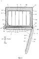
- FIG. 1 is a perspective view of an ultra-low temperature freezer according to an embodiment of the present disclosure
- FIG. 2 is a cross section of the ultra-low temperature freezer, as viewed from above, the cross section being taken along line II-II′ of FIG. 1 ;
- FIG. 3 is a perspective view of a housing illustrated in FIG. 1 with an outer door and a plurality of inner doors removed;
- FIG. 4A is a cross section of the ultra-low temperature freezer (with the outer door opened), as viewed in perspective from above, the cross section being taken along line IV-IV′ of FIG. 3 ;
- FIG. 4B is a cross section of the ultra-low temperature freezer (with the outer door closed), as viewed in perspective from above, the cross section being taken along line IV-IV′ of FIG. 3 ;
- FIG. 5 is a perspective view illustrating a straight seal member immediately after extrusion molding.
- FIG. 6 illustrates respective cross sections of modified examples of the seal member.
- ultra-low temperature freezer 1 According to an embodiment of the present disclosure, a detailed description is hereinafter provided of ultra-low temperature freezer 1 according to an embodiment of the present disclosure.
- an x-axis indicates a transverse direction of ultra-low temperature freezer 1 and more specifically, a left to right direction when a user faces ultra-low temperature freezer 1 .
- a y-axis indicates a front-back direction of ultra-low temperature freezer 1 and more specifically, a rear to front direction (i.e. a forward direction) when the user faces ultra-low temperature freezer 1 .
- a z-axis indicates a vertical direction of ultra-low temperature freezer 1 and more specifically, a perpendicularly upward direction from an ultra-low temperature freezer installation surface (that is substantially horizontal).
- ultra-low temperature freezer 1 basically includes housing 2 , outer door 3 , and machinery compartment 4 . It is to be noted that in FIG. 1 , constituent elements that cannot be visually recognized exteriorly, such as thermal insulators 23 , 33 which are described later, are indicated by broken lines.
- Housing 2 generally includes exterior body 21 and interior body 22 that are made of, for example, metal, and a plurality of thermal insulators 23 .
- Exterior body 21 defines an outside shape of housing 2 .
- Interior body 22 is provided inside exterior body 21 and defines space (hereinafter referred to as “storage space”) A for accommodating objects to store.
- a forward edge (hereinafter referred to as “opening A 1 ”) of storage space A is substantially rectangular and is parallel to a z-x plane.
- Each of the plurality of thermal insulators 23 is preferably formed of, for example, a laminate of a vacuum insulated panel and polyurethane. It is to be noted that FIGS. 1 and 2 do not illustrate all of the plurality of thermal insulators 23 for convenience' sake.
- thermal insulators 23 indicated in FIG. 1 by the broken lines include two thermal insulators 23 that are interposed between a right side of exterior body 21 and a right side of interior body 22 and one thermal insulator 23 that is interposed between a top side of exterior body 21 and a top side of interior body 22 .
- thermal insulators 23 that are respectively provided at a left side, a right side, and a rear side of housing 2 are illustrated.
- the vacuum insulated panel of thermal insulator 23 is indicated by leftward hatching, while the polyurethane of thermal insulator 23 is indicated by rightward hatching.
- Outer door 3 includes interior body 31 and exterior body 32 that are made of, for example, metal, and at least one thermal insulator 33 disposed in a space between interior body 31 and exterior body 32 .
- Outer door 3 is openable by being rotated about respective pivots of, for example, three hinges 34 through user operation. When closed, outer door 3 closes opening A 1 . On the other hand, when outer door 3 is opened, the user can open and close inner door 5 which is described later.
- thermal insulator 33 is preferably formed of a combination of a vacuum insulated panel and polyurethane. It is to be noted that in FIG. 1 , this one thermal insulator 33 is illustrated by the broken line. In FIG.
- the vacuum insulated panel of that one thermal insulator 33 is provided at inner surface S 10 of outer door 3 (refer to leftward hatching), while the polyurethane of that thermal insulator 33 is provided between the vacuum insulated panel and exterior body 32 (refer to rightward hatching).
- Outer door 3 is also provided with handle 35 that the user holds to open and close outer door 3 .
- handle 35 has lock mechanism 36 .
- Lock mechanism 36 locks outer door 3 that is closed, and unlocks to allow opening of outer door 3 . With outer door 3 locked by lock mechanism 36 , hermeticity and thermal insulation of ultra-low temperature freezer 1 can be enhanced.
- Control panel 37 internally has a control circuit board (not illustrated) and has a touch panel that enables operation and visual recognition by the user.
- the touch panel is a device that, for example, enables the user to set a target temperature (i.e. a target value for internal temperature) of storage space A and others and displays various information items including a currently preset temperature (the target value for the internal temperature).
- Machinery compartment 4 is provided, for example, below housing 2 .
- Machinery compartment 4 houses a well-known binary refrigerating system (also called cascade cycle). It is to be noted, however, that not all elements of the binary refrigerating system are housed by machinery compartment 4 .
- a lower-temperature-side evaporator is disposed between exterior body 21 and interior body 22 of housing 2 to surround storage space A, and a cascade condenser is disposed at a rear of storage space A.
- Machinery compartment 4 houses the other elements.
- a detailed description of the binary refrigerating system is provided by Japanese Patent Application Laid-Open No. 2010-096490 and others and thus is not provided in the present embodiment.
- Machinery compartment 4 may be internally provided with two unitary multistage refrigeration cycles that are controlled independently of each other.
- respective evaporators of the unitary multistage refrigeration cycles are disposed in housing 2 to surround storage space A. Even when a problem is caused to one of the unitary multistage refrigeration cycles, storage space A is maintained in an ultra-low temperature range by the other unitary multistage refrigeration cycle.
- Ultra-low temperature freezer 1 preferably also includes at least one inner door 5 and at least one storage box 6 .
- Inner door 5 is made of, for example, resin and rotates on at least one inner-door hinge (not illustrated) about a pivot that is positioned at a right edge of opening A 1 in parallel relation with the z-axis. This inner door 5 is opened and closed by the user. When closed, inner door 5 closes at least a part of opening A 1 . On the other hand, with inner door 5 opened, the user can access storage space A. Inner door 5 such as the above can enhance a thermal insulation effect on storage space A.
- Storage box 6 accommodates objects to store and is mounted on rack 7 that is provided in storage space A. To remove the objects in storage from storage box 6 , the user opens outer door 3 and inner door 5 first and then pulls storage box 6 out of storage space A.
- housing 2 includes housing-end left side S 1 , housing-end right side S 2 , rear side S 3 , housing-end peripheral part S 4 , top face S 5 , and bottom face S 6 .
- Left side S 1 faces right side S 2 in the left to right direction, and left side S 1 and right side S 2 are each formed of, for example, a plane surface that is generally parallel to a y-z plane.
- Right side S 2 faces left side S 1 at a position that is about 1,030 mm away from left side S 1 in the transverse direction (i.e. in the direction indicated by the x-axis).
- Rear side S 3 faces peripheral part S 4 in the rear to front direction
- rear side S 3 and peripheral part S 4 each include, for example, a surface that is generally parallel to the z-x plane.
- Peripheral part S 4 is a first peripheral part and faces rear side S 3 in a position that is about 793 mm away from rear side S 3 in the direction indicated by the y-axis.
- This peripheral part S 4 surrounds opening A 1 from all quarters (namely, from above, below, left, and right) along a periphery of opening A 1 .
- Bottom face S 6 faces top face S 5 in the vertical direction, and top face S 5 and bottom face S 6 each include, for example, a surface that is generally parallel to an x-y plane.
- Top face S 5 faces bottom face S 6 at a position that is about 1,540 mm away from bottom side S 6 in the vertical direction (i.e. in the direction indicated by the z-axis).
- an exterior of outer door 3 includes door-end left side S 7 , door-end right side S 8 , outer face S 9 , inner face S 10 , and door-end peripheral part S 11 . It is to be noted that FIG. 2 illustrates outer door 3 both in its closed position and in its opened position which is indicated by broken lines.
- left side S 7 faces right side S 8 in the left to right direction
- left side 87 and right side S 8 each include, for example, a surface that is generally parallel to the y-z plane.
- Right side S 8 faces left side S 7 at a position that is about 1,030 mm away from left side S 7 in the direction indicated by the x-axis.
- Left side S 7 and right side S 8 head forward (i.e. in the direction indicated by the y-axis), respectively starting from a left edge and a right edge of inner face S 10 which is described later.
- left side S 7 and right side S 8 each have a y-axis length of, for example, about 60 mm.
- inner face S 10 faces outer face S 9 in the rear to front direction.
- inner face S 10 closes opening A 1 .
- Outer face S 9 is at most about 90 mm away from inner face S 10 in the forward direction (i.e. in the direction indicated by the y-axis).
- Door-end peripheral part S 11 is a second peripheral part, defines an outer peripheral part of inner face S 10 and includes a surface that is generally parallel to the z-x plane when outer door 3 is closed.
- peripheral part S 4 faces, via seal member 10 which is described later, peripheral part S 11 in the direction that is indicated as an example of a first direction by the y-axis.
- FIG. 4A is an enlarged cross section of a front left portion of ultra-low temperature freezer 1 (with outer door 3 opened), as viewed in perspective from above, the cross section being taken along line IV-IV′ of FIG. 3 .
- FIG. 4B is an enlarged cross section of the front left portion of ultra-low temperature freezer 1 (with outer door 3 closed), as viewed in perspective from above, the cross section being taken along line IV-IV′ of FIG. 3 . To avoid complication of illustration, FIG. 4B does not have reference marks for constituent elements of seal member 10 .
- FIG. 5 is a perspective view illustrating straight seal member 10 immediately after extrusion molding.
- seal member 10 With reference to FIGS. 3 to 5 , a detailed description is hereinafter provided of seal member 10 .
- housing-end breaker 8 and door-end breaker 9 that are made of, for example, resin are preferably mounted to above-described housing-end peripheral part S 4 and door-end peripheral part S 11 , respectively.
- housing-end breaker 8 is provided on peripheral part S 4 to surround opening A 1 in a plane viewed from a direction along the y-axis.
- door-end breaker 9 is provided on peripheral part S 11 to surround opening A 1 in a plane viewed in the direction indicated by the y-axis when outer door 3 is closed.
- Seal member 10 is mounted over peripheral part S 4 via above-mentioned housing-end breaker 8 to surround opening A 1 in a plane viewed from the direction along the y-axis (refer to FIG. 3 ).
- Seal member 10 is typically made by extrusion molding of an elastic material such as rubber or resin and subsequent bending into a shape conforming with a shape of peripheral part S 4 .
- This seal member 10 includes base 101 , mounting part 102 , first air layer defining part 103 , second air layer defining part 104 , third air layer defining part 105 , first connecting part 106 , second connecting part 107 , and a plurality of ribs 108 . It is preferable that seal member 10 be integrally molded with parts 101 to 107 forming an integral structure.
- Base 101 has the shape of a rectangular frame in a plane viewed in the direction indicated by the y-axis and has a predetermined y-axis thickness.
- Base 101 is provided on housing-end breaker 8 to extend along the periphery of opening A 1 in a plane viewed from the direction along the y-axis.
- An extending direction of base 101 is hereinafter referred to as extending direction p. As illustrated in FIG. 3 , extending direction p is parallel to all sides of rectangular opening A 1 . In other words, extending direction p is parallel to the x-axis or the z-axis.
- Mounting part 102 projects rearward from a rear face of base 101 (namely, from base 101 in the y-axis negative direction). This mounting part 102 is inserted into slit 81 that is formed in housing-end breaker 8 , whereby seal member 10 is mounted to housing-end breaker 8 .
- Air layer defining parts 103 to 105 are hollow and are provided to surround the entire periphery of opening A 1 from all quarters (namely, from above, below, left, and right) while projecting forward (i.e. in the y-axis positive direction) from a front face of base 101 .
- Air layer defining parts 104 , 105 line up in second direction q in predetermined spaced relation to respective air layer defining parts 103 , 104 .
- second direction q is orthogonal to extending direction p and the direction indicated by the y-axis (i.e. first direction). More specifically, air layer defining parts 103 to 105 line up in the direction indicated by the x-axis (i.e.
- air layer defining parts 103 to 105 line up in the direction indicated by the z-axis (i.e. in the vertical direction).
- air layer defining parts 103 to 105 when air layer defining parts 103 to 105 are cut along a virtual plane that includes line IV-IV′ with outer door 3 opened, as illustrated in FIG. 4A , air layer defining parts 103 to 105 each have an inner peripheral surface in the shape of an ellipse and an outer peripheral surface in the shape of an elliptical arc.
- the virtual plane is orthogonal to extending direction p and is parallel to the y-axis.
- the ellipses respectively defining respective cross-sectional shapes of the inner peripheral surfaces have identical curvature distributions.
- the elliptical arcs respectively defining respective cross-sectional shapes of the outer peripheral surfaces have identical curvature distributions.
- First connecting part 106 surrounds the entire periphery of opening A 1 from all quarters in a plane viewed from the direction along the y-axis and connects the respective outer peripheral surfaces of air layer defining parts 103 , 104 as a bridge between these outer peripheral surfaces.
- First connecting part 106 has substantially the same shape as a y-axis end portion of second air layer defining part 104 . More specifically, an inner peripheral surface and an outer peripheral surface of first connecting part 106 are shaped like respective y-axis end portions of the second air layer defining part's inner and outer peripheral surfaces when a virtual parallel displacement is caused to these y-axis end portions. As such, the inner peripheral surface of first connecting part 106 forms an air layer with the respective outer peripheral surfaces of air layer defining parts 103 , 104 and the front face of base 101 .
- Second connecting part 107 surrounds the entire periphery of opening A 1 from all quarters in a plane viewed from the direction along the y-axis and connects the respective outer peripheral surfaces of air layer defining parts 104 , 105 as a bridge between these outer peripheral surfaces.
- an inner peripheral surface of second connecting part 107 forms an air layer with the respective outer peripheral surfaces of air layer defining parts 104 , 105 and the front face of base 101 .
- a y-axis end portion of seal member 10 is formed with four recesses C 1 to C 4 in total (i.e. first through fourth recesses C 1 to C 4 ) that surround opening A 1 from all quarters with outer door 3 closed.
- the respective outer peripheral surfaces of air layer defining parts 103 to 105 each having the above structure, the outer peripheral surface of connecting part 106 having the above structure, and an outer peripheral surface of connecting part 107 having the above structure are formed with the plurality of ribs 108 that project in the direction indicated by the y-axis.
- door-end peripheral part S 11 faces, via seal member 10 , housing-end peripheral part S 4 in a front to rear direction in close proximity to housing-end peripheral part S 4 . This is when seal member 10 is crushed between door-end breaker 9 and housing-end breaker 8 , thereby contributing to maintenance of storage space A in the ultra-low temperature range.
- This seal member 10 is formed with four recesses C 1 to C 4 in its y-axis end portion. Accordingly, moisture that remains between the y-axis end portion of seal member 10 and door-end breaker 9 when outer door 3 is closed is divided among recesses C 1 to C 4 . Because of that, even when the moisture between the y-axis end portion of seal member 10 and door-end breaker 9 freezes in these recesses C 1 to C 4 , there is a decreased area of contact between each of resulting ice pieces that are divided among recesses C 1 to C 4 and door-end breaker 9 , thus enabling reduction of difficulty in opening outer door 3 .
- seal member 10 With seal member 10 being crushed because of closed outer door 3 , the outer peripheral surfaces of seal member 10 that define recesses C 1 to C 4 move away from one another to expand respective openings of recesses C 1 to C 4 , whereby recesses C 1 to C 4 become shallower.
- seal member 10 when seal member 10 is restored to its original shape as outer door 3 is opened, the outer peripheral surfaces come close to one another to make the respective openings of recesses C 1 to C 4 smaller, whereby recesses C 1 to C 4 become deeper.
- the ice pieces that have respectively frozen in recesses C 1 to C 4 with outer door 3 closed are forced out of recesses C 1 to C 4 . Consequently, recesses C 1 to C 4 can have reduced remains. In this way, the difficulty in opening outer door 3 can be reduced.
- cleaning of recesses C 1 to C 4 can be a lightened burden for the user.
- the respective outer peripheral surfaces of air layer defining parts 103 to 105 and the respective outer peripheral surfaces of connecting parts 106 , 107 are each provided with at least one rib 108 to be structurally preferable.
- the y-axis end portion of seal member 10 makes line contact with door-end breaker 9 , whereby moisture that remains between the y-axis end portion and door-end breaker 9 can be divided with more reliability compared to cases where only recesses C 1 to C 4 are provided.
- the plurality of ribs 108 provided on the outer peripheral surfaces an increased number of divided ice pieces can be obtained.
- An area of contact between each of the divided ice pieces and door-end breaker 9 decreases according to the number of divisions, so that even when moisture between the y-axis end portion of seal member 10 and door-end breaker 9 freezes between these ribs 108 , the difficulty in opening outer door 3 can be reduced even further.
- Connecting part 106 connects two adjacent air layer defining parts 103 , 104 in spaced relation to the front face of base 101 .
- the same goes for connecting part 107 .
- recesses C 1 to C 4 are relatively shallow, thus facilitating cleaning of recesses C 1 to C 4 for the user.
- cleaning must be done between air layer defining parts 103 and 104 as well as between air layer defining parts 104 and 105 , thus being time-consuming for the user.
- Seal member 10 has, in addition to respective air layers of air layer defining parts 103 to 105 , the air layers respectively added by connecting parts 106 , 107 .
- the five air layers in total line up in second direction q, thereby enabling respective improvements in the hermeticity and the thermal insulation of ultra-low temperature freezer 1 .
- each of air layer defining parts 103 to 105 each bend, at a midpoint of extension in the direction indicated by the y-axis, to be nonparallel to the y-axis. Both sides extending from that bending point are nonparallel to the y-axis.
- each of air layer defining parts 103 to 105 easily crushes toward base 101 under a load from the direction along the y-axis.
- the respective outer peripheral surfaces of air layer defining parts 103 to 105 have the identical curvature distributions.
- the respective inner peripheral surfaces of air layer defining parts 103 to 105 have the identical curvature distributions.
- respective curvature distributions of the outer and inner peripheral surfaces of each of connecting parts 106 , 107 are respectively identical to the respective curvature distributions of the outer and inner peripheral surfaces of air layer defining part 103 or the like.
- an interval between adjacent air layer defining parts 103 , 104 is equal to an interval between adjacent air layer defining parts 104 , 105 .
- air layer defining parts 103 to 105 crush generally in a similar manner under a load that is applied to seal member 10 from the direction along the y-axis when outer door 3 is closed. Accordingly, with outer door 3 closed, external heat is not easily introduced into storage space A, whereby the hermeticity and the thermal insulation of ultra-low temperature freezer 1 become stable.
- air layer defining parts 103 to 105 each have a cross section of substantially elliptical shape
- connecting parts 106 , 107 each have a cross section having the shape of an elliptical arc.
- the cross section of each of air layer defining parts 103 to 105 may have the shape of a perfect circle.
- the cross section of connecting part 106 may be shaped like a y-axis end portion of the perfect circle of air layer defining part 104 when a virtual parallel displacement in second direction q is caused to this y-axis end portion.
- each of air layer defining parts 103 to 105 may have the shape of a hexagon or a pentagon.
- the cross section of connecting part 106 , 107 may be shaped like a y-axis end portion of the hexagon or the pentagon of corresponding one of air layer defining parts 103 to 105 when a parallel displacement in the direction indicated by the x-axis is caused to this y-axis end portion.
- the cross section of each of air layer defining parts 103 to 105 may have the shape of a semicircle or a half ellipse.
- the cross section of connecting part 106 , 107 may be shaped like a y-axis end portion of the semicircle or the half ellipse of corresponding one of air layer defining parts 103 to 105 when a parallel displacement in the direction indicated by the x-axis is caused to this y-axis end portion.
- each of air layer defining parts 103 to 105 may have the shape of a half octagon.
- the cross section of connecting part 106 , 107 may be shaped like a y-axis end portion of the half octagon of corresponding one of air layer defining parts 103 to 105 when a parallel displacement in the direction indicated by the x-axis is caused to this y-axis end portion.
- air layer defining parts 103 to 105 illustrated in each of the fourth to lowermost rows from the top in FIG. 6 although not both sides of each of an inner and an outer peripheral surface extend from a bending point to be nonparallel to the y-axis, one of those sides is nonparallel to the y-axis. Even in this case, air layer defining parts 103 to 105 easily crush toward base 101 under a load from the direction along the y-axis.
- seal member 10 is provided over peripheral part S 4 of housing 2 .
- seal member 10 is not limited to this.
- Seal member 10 may be provided over peripheral part S 11 of outer door 3 .
- Seal member 10 has been described as including three air layer defining parts 103 to 105 and two connecting parts 106 , 107 . However, seal member 10 is not limited to this. Seal member 10 only has to include at least two air layer defining parts and at least one connecting part.
- the plurality of ribs 108 are not necessary constituent elements and may be provided as needed.
- An ultra-low temperature freezer can reduce freezing-induced difficulty in opening an outer door and thus is suitable for use in a biomedical application and others.
Landscapes
- Engineering & Computer Science (AREA)
- Chemical & Material Sciences (AREA)
- Combustion & Propulsion (AREA)
- Physics & Mathematics (AREA)
- Mechanical Engineering (AREA)
- Thermal Sciences (AREA)
- General Engineering & Computer Science (AREA)
- Refrigerator Housings (AREA)
- Cold Air Circulating Systems And Constructional Details In Refrigerators (AREA)
Applications Claiming Priority (3)
| Application Number | Priority Date | Filing Date | Title |
|---|---|---|---|
| JP2016-048222 | 2016-03-11 | ||
| JP2016048222 | 2016-03-11 | ||
| PCT/JP2017/008316 WO2017154733A1 (ja) | 2016-03-11 | 2017-03-02 | 超低温フリーザ |
Related Parent Applications (1)
| Application Number | Title | Priority Date | Filing Date |
|---|---|---|---|
| PCT/JP2017/008316 Continuation WO2017154733A1 (ja) | 2016-03-11 | 2017-03-02 | 超低温フリーザ |
Publications (2)
| Publication Number | Publication Date |
|---|---|
| US20190011176A1 US20190011176A1 (en) | 2019-01-10 |
| US10627155B2 true US10627155B2 (en) | 2020-04-21 |
Family
ID=59789254
Family Applications (1)
| Application Number | Title | Priority Date | Filing Date |
|---|---|---|---|
| US16/128,437 Active US10627155B2 (en) | 2016-03-11 | 2018-09-11 | Ultra-low temperature freezer |
Country Status (6)
| Country | Link |
|---|---|
| US (1) | US10627155B2 (ko) |
| EP (1) | EP3428558B1 (ko) |
| JP (1) | JP6603397B2 (ko) |
| KR (1) | KR102196253B1 (ko) |
| CN (1) | CN108700364B (ko) |
| WO (1) | WO2017154733A1 (ko) |
Cited By (1)
| Publication number | Priority date | Publication date | Assignee | Title |
|---|---|---|---|---|
| USD1030606S1 (en) | 2022-07-01 | 2024-06-11 | Oxford Instruments Nanotechnology Tools Limited | Cryogenic cooling system |
Families Citing this family (3)
| Publication number | Priority date | Publication date | Assignee | Title |
|---|---|---|---|---|
| EP3783285A4 (en) * | 2018-05-25 | 2021-06-23 | PHC Holdings Corporation | SEALING STRUCTURE FOR A COOLING DEVICE AND COOLING DEVICE |
| GB201818126D0 (en) * | 2018-11-07 | 2018-12-19 | B Medical Systems Sarl | Freezers and refigerators |
| US11306967B2 (en) | 2020-02-10 | 2022-04-19 | Whirlpool Corporation | Drawer gasket seal assembly |
Citations (16)
| Publication number | Priority date | Publication date | Assignee | Title |
|---|---|---|---|---|
| US2908949A (en) * | 1957-11-12 | 1959-10-20 | Gen Tire & Rubber Co | Honeycomb plastic door gasket |
| US2968845A (en) * | 1958-05-09 | 1961-01-24 | Foster Refrigerator Corp | Refrigerator door construction |
| US3078134A (en) * | 1961-06-12 | 1963-02-19 | Gen Motors Corp | Refrigerator door sealing |
| US3178778A (en) * | 1961-10-10 | 1965-04-20 | H O Canfield Company Inc | Refrigerator seal |
| US4138049A (en) * | 1976-10-29 | 1979-02-06 | The Pantasote Company | Dual function sealing gasket |
| JPS57100666U (ko) | 1980-12-12 | 1982-06-21 | ||
| US4462646A (en) * | 1982-09-29 | 1984-07-31 | Whirlpool Corporation | Insulated cabinet construction for chest freezers |
| US4826010A (en) * | 1987-07-31 | 1989-05-02 | White Consolidated Industries, Inc. | Refrigeration cabinet construction |
| US5289657A (en) * | 1992-03-13 | 1994-03-01 | The Standard Products Company | Refrigerator gasket and retainer |
| JP3018297U (ja) | 1995-05-18 | 1995-11-14 | 株式会社タック | 目地シール材 |
| JPH11311477A (ja) | 1998-04-28 | 1999-11-09 | Hoshizaki Electric Co Ltd | 冷却貯蔵庫のドアシール構造 |
| JP2005147476A (ja) | 2003-11-13 | 2005-06-09 | Hoshizaki Electric Co Ltd | 貯蔵庫 |
| JP2006046852A (ja) | 2004-08-06 | 2006-02-16 | Hoshizaki Electric Co Ltd | 冷却貯蔵庫 |
| JP2010096490A (ja) | 2008-09-16 | 2010-04-30 | Sanyo Electric Co Ltd | 冷凍装置 |
| US20120103992A1 (en) | 2010-10-28 | 2012-05-03 | Sanyo Electric Co., Ltd. | Plug member and low-temperature storage |
| US8944539B2 (en) * | 2011-04-18 | 2015-02-03 | Whirlpool S.A. | Sealing system for refrigerator |
Family Cites Families (13)
| Publication number | Priority date | Publication date | Assignee | Title |
|---|---|---|---|---|
| US1883609A (en) * | 1930-05-31 | 1932-10-18 | William J Dennis | Gasket |
| JPS4927892B1 (ko) * | 1967-02-09 | 1974-07-22 | ||
| JPS5553907Y2 (ko) * | 1975-08-27 | 1980-12-13 | ||
| JPS5750464Y2 (ko) * | 1978-03-29 | 1982-11-04 | ||
| FR2445916A1 (fr) * | 1979-01-04 | 1980-08-01 | Refrigeration Cie Caladoise | Appareil de production de froid, muni d'un systeme de reequilibrage de pressions |
| JPS5724358U (ko) * | 1980-07-17 | 1982-02-08 | ||
| JPS6114190U (ja) * | 1984-06-30 | 1986-01-27 | 横浜ゴム株式会社 | 艙口蓋用パツキン |
| CN1045641A (zh) * | 1989-03-12 | 1990-09-26 | 郭军 | 凹凸型冷藏恒温箱门封 |
| US5600966A (en) * | 1995-05-19 | 1997-02-11 | Forma Scientific, Inc. | Ultra low temperature split door freezer |
| CN2692602Y (zh) * | 2004-04-26 | 2005-04-13 | 威海安泰电子制冷设备有限公司 | 超低温双密封门 |
| US7823331B2 (en) * | 2005-11-16 | 2010-11-02 | Holm Industries, Inc. | French door seal having a magnetic pair |
| WO2011142128A1 (ja) * | 2010-05-11 | 2011-11-17 | パナソニック株式会社 | 冷蔵庫 |
| US9506687B2 (en) * | 2013-06-08 | 2016-11-29 | Hefei Hualing Co., Ltd. | Refrigeration device |
-
2017
- 2017-03-02 CN CN201780015624.2A patent/CN108700364B/zh active Active
- 2017-03-02 WO PCT/JP2017/008316 patent/WO2017154733A1/ja active Application Filing
- 2017-03-02 JP JP2018504423A patent/JP6603397B2/ja active Active
- 2017-03-02 KR KR1020187025170A patent/KR102196253B1/ko active IP Right Grant
- 2017-03-02 EP EP17763073.8A patent/EP3428558B1/en active Active
-
2018
- 2018-09-11 US US16/128,437 patent/US10627155B2/en active Active
Patent Citations (19)
| Publication number | Priority date | Publication date | Assignee | Title |
|---|---|---|---|---|
| US2908949A (en) * | 1957-11-12 | 1959-10-20 | Gen Tire & Rubber Co | Honeycomb plastic door gasket |
| US2968845A (en) * | 1958-05-09 | 1961-01-24 | Foster Refrigerator Corp | Refrigerator door construction |
| US3078134A (en) * | 1961-06-12 | 1963-02-19 | Gen Motors Corp | Refrigerator door sealing |
| US3178778A (en) * | 1961-10-10 | 1965-04-20 | H O Canfield Company Inc | Refrigerator seal |
| US4138049A (en) * | 1976-10-29 | 1979-02-06 | The Pantasote Company | Dual function sealing gasket |
| JPS57100666U (ko) | 1980-12-12 | 1982-06-21 | ||
| US4462646A (en) * | 1982-09-29 | 1984-07-31 | Whirlpool Corporation | Insulated cabinet construction for chest freezers |
| US4826010A (en) * | 1987-07-31 | 1989-05-02 | White Consolidated Industries, Inc. | Refrigeration cabinet construction |
| US5289657A (en) * | 1992-03-13 | 1994-03-01 | The Standard Products Company | Refrigerator gasket and retainer |
| JP3018297U (ja) | 1995-05-18 | 1995-11-14 | 株式会社タック | 目地シール材 |
| JPH11311477A (ja) | 1998-04-28 | 1999-11-09 | Hoshizaki Electric Co Ltd | 冷却貯蔵庫のドアシール構造 |
| JP2005147476A (ja) | 2003-11-13 | 2005-06-09 | Hoshizaki Electric Co Ltd | 貯蔵庫 |
| JP2006046852A (ja) | 2004-08-06 | 2006-02-16 | Hoshizaki Electric Co Ltd | 冷却貯蔵庫 |
| JP2010096490A (ja) | 2008-09-16 | 2010-04-30 | Sanyo Electric Co Ltd | 冷凍装置 |
| US20100326109A1 (en) | 2008-09-16 | 2010-12-30 | Sanyo Electric Co., Ltd. | Refrigerating apparatus |
| US20120103992A1 (en) | 2010-10-28 | 2012-05-03 | Sanyo Electric Co., Ltd. | Plug member and low-temperature storage |
| JP2012093055A (ja) | 2010-10-28 | 2012-05-17 | Sanyo Electric Co Ltd | 栓部材、低温貯蔵庫 |
| JP5671675B2 (ja) | 2010-10-28 | 2015-02-18 | パナソニックヘルスケアホールディングス株式会社 | 栓部材、低温貯蔵庫 |
| US8944539B2 (en) * | 2011-04-18 | 2015-02-03 | Whirlpool S.A. | Sealing system for refrigerator |
Non-Patent Citations (1)
| Title |
|---|
| International Search Report and Written Opinion issued in International Patent Application No. PCT/JP2017/008316 dated May 23, 2017; with partial English translation |
Cited By (2)
| Publication number | Priority date | Publication date | Assignee | Title |
|---|---|---|---|---|
| USD1030606S1 (en) | 2022-07-01 | 2024-06-11 | Oxford Instruments Nanotechnology Tools Limited | Cryogenic cooling system |
| USD1042297S1 (en) | 2022-07-01 | 2024-09-17 | Oxford Instruments Nanotechnology Tools Limited | Cryogenic cooling system |
Also Published As
| Publication number | Publication date |
|---|---|
| CN108700364B (zh) | 2020-07-03 |
| WO2017154733A1 (ja) | 2017-09-14 |
| JP6603397B2 (ja) | 2019-11-06 |
| CN108700364A (zh) | 2018-10-23 |
| KR20180108770A (ko) | 2018-10-04 |
| US20190011176A1 (en) | 2019-01-10 |
| JPWO2017154733A1 (ja) | 2018-10-04 |
| EP3428558A1 (en) | 2019-01-16 |
| EP3428558A4 (en) | 2019-03-27 |
| KR102196253B1 (ko) | 2020-12-29 |
| EP3428558B1 (en) | 2020-02-12 |
Similar Documents
| Publication | Publication Date | Title |
|---|---|---|
| US10627155B2 (en) | Ultra-low temperature freezer | |
| US10145604B2 (en) | Refrigerator | |
| US9970703B2 (en) | Refrigerator and manufacturing method thereof | |
| EP2730870B1 (en) | Refrigerator and method of manufacturing inner door thereof | |
| US9322474B2 (en) | Refrigerator | |
| US10429121B2 (en) | Refrigerator | |
| KR20140060431A (ko) | 냉장고 및 그 내부 도어의 제조 방법 | |
| US20180087825A1 (en) | Domestic refrigeration appliance having an external housing of an icemaker and a frame at the front | |
| US10782061B2 (en) | Ultra low-temperature freezer | |
| CN110177984B (zh) | 冰箱 | |
| US20160265836A1 (en) | Refrigerator | |
| JP6444759B2 (ja) | 箱体の扉 | |
| AU2015401979A1 (en) | Refrigerator | |
| JP6197172B2 (ja) | 冷蔵庫 | |
| US11333428B2 (en) | Heat insulating structure for cooling device, and cooling device | |
| WO2016143258A1 (ja) | 冷蔵庫 | |
| WO2022054308A1 (ja) | 冷蔵庫 | |
| TR2022021073A2 (tr) | Bi̇r soğutucu ci̇haz i̇çi̇n bi̇r raf terti̇bati ve buna i̇li̇şki̇n bi̇r yöntem | |
| CN108240155B (zh) | 家用电器 | |
| JP2016130613A (ja) | 冷蔵庫 | |
| JP2022166699A (ja) | 冷蔵庫 | |
| KR20120126407A (ko) | 복합형 냉장고 | |
| KR20140091378A (ko) | 냉장고 선반용 장식재, 그 제조 방법 및 냉장고 |
Legal Events
| Date | Code | Title | Description |
|---|---|---|---|
| AS | Assignment |
Owner name: PHC HOLDINGS CORPORATION, JAPAN Free format text: ASSIGNMENT OF ASSIGNORS INTEREST;ASSIGNOR:OKADA, TADASHI;REEL/FRAME:046845/0855 Effective date: 20180821 |
|
| FEPP | Fee payment procedure |
Free format text: ENTITY STATUS SET TO UNDISCOUNTED (ORIGINAL EVENT CODE: BIG.); ENTITY STATUS OF PATENT OWNER: LARGE ENTITY |
|
| STPP | Information on status: patent application and granting procedure in general |
Free format text: DOCKETED NEW CASE - READY FOR EXAMINATION |
|
| STPP | Information on status: patent application and granting procedure in general |
Free format text: NON FINAL ACTION MAILED |
|
| STPP | Information on status: patent application and granting procedure in general |
Free format text: RESPONSE TO NON-FINAL OFFICE ACTION ENTERED AND FORWARDED TO EXAMINER |
|
| STPP | Information on status: patent application and granting procedure in general |
Free format text: NOTICE OF ALLOWANCE MAILED -- APPLICATION RECEIVED IN OFFICE OF PUBLICATIONS |
|
| STCF | Information on status: patent grant |
Free format text: PATENTED CASE |
|
| MAFP | Maintenance fee payment |
Free format text: PAYMENT OF MAINTENANCE FEE, 4TH YEAR, LARGE ENTITY (ORIGINAL EVENT CODE: M1551); ENTITY STATUS OF PATENT OWNER: LARGE ENTITY Year of fee payment: 4 |