US10609772B2 - Microwave heating device - Google Patents
Microwave heating device Download PDFInfo
- Publication number
- US10609772B2 US10609772B2 US15/110,567 US201515110567A US10609772B2 US 10609772 B2 US10609772 B2 US 10609772B2 US 201515110567 A US201515110567 A US 201515110567A US 10609772 B2 US10609772 B2 US 10609772B2
- Authority
- US
- United States
- Prior art keywords
- cavity
- microwave
- microwave generator
- air
- exemplary embodiment
- Prior art date
- Legal status (The legal status is an assumption and is not a legal conclusion. Google has not performed a legal analysis and makes no representation as to the accuracy of the status listed.)
- Active, expires
Links
Images


Classifications
-
- H—ELECTRICITY
- H05—ELECTRIC TECHNIQUES NOT OTHERWISE PROVIDED FOR
- H05B—ELECTRIC HEATING; ELECTRIC LIGHT SOURCES NOT OTHERWISE PROVIDED FOR; CIRCUIT ARRANGEMENTS FOR ELECTRIC LIGHT SOURCES, IN GENERAL
- H05B6/00—Heating by electric, magnetic or electromagnetic fields
- H05B6/64—Heating using microwaves
- H05B6/642—Cooling of the microwave components and related air circulation systems
-
- H—ELECTRICITY
- H05—ELECTRIC TECHNIQUES NOT OTHERWISE PROVIDED FOR
- H05B—ELECTRIC HEATING; ELECTRIC LIGHT SOURCES NOT OTHERWISE PROVIDED FOR; CIRCUIT ARRANGEMENTS FOR ELECTRIC LIGHT SOURCES, IN GENERAL
- H05B6/00—Heating by electric, magnetic or electromagnetic fields
- H05B6/64—Heating using microwaves
- H05B6/6447—Method of operation or details of the microwave heating apparatus related to the use of detectors or sensors
- H05B6/645—Method of operation or details of the microwave heating apparatus related to the use of detectors or sensors using temperature sensors
-
- H—ELECTRICITY
- H05—ELECTRIC TECHNIQUES NOT OTHERWISE PROVIDED FOR
- H05B—ELECTRIC HEATING; ELECTRIC LIGHT SOURCES NOT OTHERWISE PROVIDED FOR; CIRCUIT ARRANGEMENTS FOR ELECTRIC LIGHT SOURCES, IN GENERAL
- H05B6/00—Heating by electric, magnetic or electromagnetic fields
- H05B6/64—Heating using microwaves
- H05B6/647—Aspects related to microwave heating combined with other heating techniques
- H05B6/6473—Aspects related to microwave heating combined with other heating techniques combined with convection heating
- H05B6/6476—Aspects related to microwave heating combined with other heating techniques combined with convection heating the refrigerating air being used for convection
-
- H—ELECTRICITY
- H05—ELECTRIC TECHNIQUES NOT OTHERWISE PROVIDED FOR
- H05B—ELECTRIC HEATING; ELECTRIC LIGHT SOURCES NOT OTHERWISE PROVIDED FOR; CIRCUIT ARRANGEMENTS FOR ELECTRIC LIGHT SOURCES, IN GENERAL
- H05B6/00—Heating by electric, magnetic or electromagnetic fields
- H05B6/64—Heating using microwaves
- H05B6/70—Feed lines
- H05B6/707—Feed lines using waveguides
-
- H—ELECTRICITY
- H05—ELECTRIC TECHNIQUES NOT OTHERWISE PROVIDED FOR
- H05B—ELECTRIC HEATING; ELECTRIC LIGHT SOURCES NOT OTHERWISE PROVIDED FOR; CIRCUIT ARRANGEMENTS FOR ELECTRIC LIGHT SOURCES, IN GENERAL
- H05B2206/00—Aspects relating to heating by electric, magnetic, or electromagnetic fields covered by group H05B6/00
- H05B2206/04—Heating using microwaves
- H05B2206/044—Microwave heating devices provided with two or more magnetrons or microwave sources of other kind
Definitions
- the present disclosure relates to a microwave heating device for heating an object to be heated by microwaves (hereinafter, referred to as microwave heating).
- some microwave heating devices for cooking an object to be heated such as food by microwave heating have two magnetrons (for example, PTL 1). Consequently, it is possible to increase output of microwaves to cook for a short time.
- microwave heating device is further downsized particularly in a right-left direction and a front-back direction.
- a conventional configuration is not sufficient to solve this problem, and there is room for improvement.
- the present disclosure solves the above problem, and an object of the present disclosure is to downsize a microwave heating device including a plurality of magnetrons.
- a microwave heating device includes: a cavity housing an object to be heated; a door openably provided on a front surface of the cavity; first and second microwave generators that generate microwaves; an inverter unit; a cooling unit; and first and second waveguides.
- the inverter unit drives the first and second microwave generators.
- the cooling unit cools the first and second microwave generators and the inverter unit.
- the first and second waveguides supply, to the cavity, the microwaves generated by the first and second microwave generators.
- the first and second microwave generators are disposed side by side in a right-left direction below a bottom surface of the cavity.
- the inverter unit and the cooling unit are disposed from the first and second microwave generators toward a front side in order, and the first and second waveguides are provided so as to extend in a front-back direction from the first and second microwave generators, respectively.
- a microwave heating device including a plurality of magnetrons can be further downsized in a right-left direction.
- FIG. 1 is a perspective view of a heating cooker according to a first exemplary embodiment of the present disclosure.
- FIG. 2 is a perspective view of the heating cooker according to the first exemplary embodiment.
- FIG. 3 is a front view of the heating cooker according to the first exemplary embodiment.
- FIG. 4 is a perspective view of the heating cooker according to the first exemplary embodiment.
- FIG. 5A is a longitudinal sectional view of the heating cooker according to the first exemplary embodiment.
- FIG. 5B is a partially enlarged view of FIG. 5A .
- FIG. 6 is a front view of a back wall of a cavity according to the first exemplary embodiment.
- FIG. 7 is a front view of a convection device according to the first exemplary embodiment.
- FIG. 8 is a perspective view of the convection device according to the first exemplary embodiment.
- FIG. 9 is an exploded perspective view of a hot air generation mechanism included in the convection device according to the first exemplary embodiment.
- FIG. 10 is a sectional view taken along line 10 - 10 of FIG. 7 .
- FIG. 11 is a perspective view of a convection heater included in the hot air generation mechanism according to the first exemplary embodiment.
- FIG. 12 is a perspective view of a circulation fan included in the convection device according to the first exemplary embodiment.
- FIG. 13 is a perspective view of an air guide included in the convection device according to the first exemplary embodiment.
- FIG. 14A is a perspective view of the air guide included in the convection device according to the first exemplary embodiment.
- FIG. 14B is a diagram in which first and second wind direction plates are omitted in FIG. 14A .
- FIG. 15 is a diagram illustrating a circulation flow of an inside of the cavity according to the first exemplary embodiment.
- FIG. 16 is a timing chart according to an example of heating operation of the heating cooker according to the first exemplary embodiment.
- FIG. 17 is a plan view of location of magnetrons and waveguides according to the first exemplary embodiment.
- FIG. 18 is a plan view illustrating location of the magnetrons, inverters, the waveguides, and cooling fans according to the first exemplary embodiment.
- FIG. 19 is a perspective view illustrating location of the magnetrons, the inverters, the waveguides, and the cooling fans according to the first exemplary embodiment.
- FIG. 20 is a diagram illustrating a flow of cooling air by a cooling mechanism for the magnetrons and a fan drive unit according to the first exemplary embodiment.
- FIG. 21 is a diagram illustrating a flow of cooling air by the cooling mechanism for the magnetrons and the fan drive unit according to the first exemplary embodiment.
- FIG. 22 is a diagram illustrating a flow of cooling air by the cooling mechanism for the magnetrons and the fan drive unit according to the first exemplary embodiment.
- FIG. 23 is an enlarged view of A part of FIG. 4 .
- FIG. 24 is an enlarged view of E part of FIG. 21 .
- FIG. 25 is a side view of a hinge structure according to the first exemplary embodiment.
- FIG. 26 is a perspective view of the hinge structure according to the first exemplary embodiment.
- FIG. 27A is a perspective view of the hinge structure according to the first exemplary embodiment.
- FIG. 27B is an enlarged view of G part of FIG. 27A .
- FIG. 28A is a sectional view taken along line 28 A- 28 A of FIG. 25 .
- FIG. 28B is an enlarged view of H part of FIG. 28A .
- FIG. 29 is a side view of the hinge structure according to the first exemplary embodiment.
- FIG. 30 is a plan view illustrating location of magnetrons, inverters, and waveguides of a heating cooker according to a modification of the first exemplary embodiment.
- FIG. 31 is a perspective view of a convection device according to a second exemplary embodiment.
- FIG. 32 is a front view of a back wall of a cavity according to the second exemplary embodiment of the present disclosure.
- FIG. 33 is a perspective view illustrating an inside of the cavity according to the second exemplary embodiment.
- a microwave heating device includes: a cavity housing an object to be heated; a door openably provided on a front surface of the cavity; first and second microwave generators that generate microwaves; an inverter unit; a cooling unit; and first and second waveguides.
- the inverter unit drives the first and second microwave generators.
- the cooling unit cools the first and second microwave generators and the inverter unit.
- the first and second waveguides supply, to the cavity, the microwaves generated by the first and second microwave generators.
- the first and second microwave generators are disposed side by side in a right-left direction below a bottom surface of the cavity.
- the inverter unit and the cooling unit are disposed from the first and second microwave generators toward a front side in order, and the first and second waveguides are provided so as to extend in a front-back direction from the first and second microwave generators, respectively.
- the microwave heating device having a plurality of the microwave generators, it is possible to effectively utilize a space inside a machine chamber. As a result, the microwave heating device can be further downsized in a right-left direction.
- the microwave heating device further has a convection device that is provided behind the cavity to be communicated with the cavity, and supplies hot air to the cavity, wherein the first and second microwave generators are provided below the convection device.
- the microwave heating device having a convection heating function can be further downsized in the right-left direction by the utilization of the space inside the machine chamber.
- the microwave heating device further has an outside air suction port for taking outside air in, the outside air suction port being provided below the door, wherein the cooling unit and the inverter unit are provided below the cavity.
- the outside air suction port is provided below the door, and therefore it is possible to ensure a suction path of cooling air even in a case where a plurality of the microwave heating devices are disposed side by side in the right-left direction.
- the first and second waveguides have first and second microwave radiation holes that are openings for supplying microwaves into the cavity, and have H corner shapes curved toward the first and second microwave radiation holes at 90 degrees, respectively.
- the H corner shapes are provided, so that it is possible to improve intensity of the microwaves radiated in the cavity.
- FIG. 1 to FIG. 4 each are a diagram illustrating appearance of heating cooker 30 according to a first exemplary embodiment of the present disclosure.
- FIG. 1 is a perspective view of heating cooker 30 with door 11 closed.
- FIG. 2 is a perspective view of heating cooker 30 with door 11 opened.
- FIG. 3 is a front view of heating cooker 30 with door 11 opened.
- FIG. 4 is a perspective view of heating cooker 30 with door 11 detached, as viewed obliquely from a lower part.
- Heating cooker 30 is particularly a microwave oven for business use used in a convenience store, a fast food restaurant, or the like.
- heating cooker 30 includes body 1 that is an outer case, machine chamber 31 for supporting body 1 , and door 11 mounted on front surface 1 a of body 1 .
- cavity 2 is provided inside body 1 .
- Cavity 2 is a housing having a substantially rectangular parallelepiped shape provided with an opening in a single surface in order to house an object to be heated in the housing.
- a side on which the opening of cavity 2 is provided is defined as a front side of heating cooker 30
- a back side of cavity 2 is defined as a back side of heating cooker 30
- a right side and a left side as heating cooker 30 is viewed from the front side are referred to as a right side and a left side, respectively.
- Door 11 is mounted on front surface 1 a of body 1 so as to close the opening of cavity 2 , and is openably closed with hinges as a center by manipulation of handle 12 , the hinges being provided at lower parts on both sides of door 11 .
- An object to be heated inside cavity 2 is heated by a microwave or the like in a state where door 11 is closed (refer to FIG. 1 ), and the object to be heated is housed in cavity 2 , or is taken out of cavity 2 in a state where door 11 is opened (refer to FIG. 2 ).
- Operation part 41 is provided on front surface 1 a of body 1 on a right side of door 11 , and includes buttons and a display screen for manipulation of heating cooker 30 by a user.
- wire rack 9 made of stainless steel, and tray 8 made of ceramic (specifically, made of cordierite) are provided inside cavity 2 .
- Wire rack 9 is a placing part formed of a net-like member in order to place an object to be heated.
- Tray 8 is provided below wire rack 9 , and receives fat and the like dripped down from the object to be heated placed on wire rack 9 .
- grill heater 10 is provided in a vicinity of ceiling 2 b inside cavity 2 .
- Grill heater 10 is configured by a single sheathed heater having a bent shape, and heats the inside of cavity 2 by radiant heat.
- exhaust holes 46 for discharging, to an outside, steam and the like inside cavity 2 is provided.
- Exhaust duct 42 (not illustrated) described later with reference to FIG. 21 , FIG. 22 and the like is connected to exhaust holes 46 .
- FIG. 5A is a longitudinal sectional view in a front-back direction of heating cooker 30
- FIG. 5B is a partially enlarged sectional view of FIG. 5A .
- tray 8 is placed on plate receiving base 7 .
- Plate receiving base 7 is provided above bottom surface 2 c of cavity 2 , and supports tray 8 .
- plate receiving base 7 is configured by a plate made of ceramic which is capable of transmitting a microwave.
- Stirrer 32 is provided between plate receiving base 7 and bottom surface 2 c of cavity 2 , and is a rotator blade that rotates about stirrer shaft 34 in order to stir a microwave.
- Motor 33 is provided in machine chamber 31 , and drives stirrer 32 .
- microwave generator 3 that generates a microwave
- inverter unit 4 that drives microwave generator 3
- cooling unit 5 that cools microwave generator 3 and inverter unit 4
- Microwave generator 3 is configured by two magnetrons as described later, and generates microwaves supplied into the cavity 2 .
- a total output of the two magnetrons is 1200 W to 1300 W.
- Waveguide part 17 is connected to microwave generator 3 , is provided below bottom surface 2 c of cavity 2 so as to extend up to stirrer shaft 34 along bottom surface 2 c , and guides microwaves generated by microwave generator 3 to stirrer shaft 34 .
- Waveguide part 17 is configured by two waveguides as described later.
- a hole (not illustrated) for allowing stirrer shaft 34 to pass is provided, and microwave radiation holes (not illustrated) for emitting microwaves are provided in a vicinity of the hole. Details of the microwave radiation holes are described later.
- Antenna 6 is provided in waveguide part 17 , and transmits, to the microwave radiation holes, microwaves generated by microwave generator 3 .
- the microwaves transmitted into waveguide part 17 by antenna 6 are radiated into cavity 2 through the microwave radiation holes formed in waveguide part 17 and the opening (not illustrated) in bottom surface 2 c , and are stirred by stirrer 32 .
- inverter unit 4 is disposed in front of microwave generator 3 , and drives microwave generator 3 .
- Inverter unit 4 is configured by two inverters as described later.
- Cooling unit 5 is disposed in front of inverter unit 4 , and cools microwave generator 3 and inverter unit 4 . Cooling unit 5 is configured by four cooling fans as described later.
- Front grill 31 a is an outside air suction port for taking outside air into machine chamber 31 .
- Cooling unit 5 takes the outside air from front grill (Front grille) 31 a of machine chamber 31 to send the outside air backward, so that cooling unit 5 cools inverter unit 4 and microwave generator 3 in order.
- Exhaust duct 45 is provided on a back side of body 1 , and exhausts, outside heating cooker 30 , the air that has cooled inverter unit 4 and microwave generator 3 .
- a plurality of openings 22 are formed in back wall 2 d of cavity 2 . Openings 22 in this exemplary embodiment are a plurality of punching holes formed by punching in back wall 2 d .
- Convection device 35 for generating hot air to be supplied into cavity 2 is provided behind back wall 2 d . Convection device 35 is partitioned from cavity 2 by back wall 2 d , and is communicated with cavity 2 through openings 22 .
- FIG. 6 A front view of back wall 2 d is illustrated in FIG. 6 .
- back wall 2 d is formed as a substantially rectangular metal plate.
- Openings 22 include first holes formed as a group of punching holes at a substantially central part of back wall 2 d , and second holes formed as a group of punching holes below the first holes.
- the second holes are formed so as to distribute more widely in a right-left direction than the first holes.
- the first holes function as suction ports 22 a to convection device 35
- the second holes function as discharge ports 22 b from convection device 35 .
- a diameter of each suction port 22 a and a diameter of each discharge port 22 b in this exemplary embodiment each are about twice, namely 10 mm.
- Suction ports 22 a and discharge ports 22 b are formed so as to have such diameters, so that it is possible to suppress an amount of microwaves passing through openings 22 to leak from cavity 2 to convection device 35 within an allowable range, while minimizing pressure of air when the microwaves pass through opening 22 .
- hot air generation mechanism 36 for generating hot air which is formed by a plurality of members, is provided in convection device 35 .
- Hot air generation mechanism 36 sucks, into convection device 35 , air in cavity 2 , and sends out the air in convection device 35 as hot air, into cavity 2 .
- Hot air generation mechanism 36 supplies hot air into cavity 2 , so that a circulation flow of the hot air is generated in cavity 2 .
- heating cooker 30 heating by radiation using grill heater 10 provided in cavity 2 , microwave heating using microwave generator 3 , and heating by the circulation flow of hot air using hot air generation mechanism 36 of convection device 35 can be separately or simultaneously performed.
- a heater is not disposed below an object to be heated, and therefore liquid such as fat dropping down from the object to be heated never comes into contact with the heater, and smoke or ignition never occurs.
- An example of a specific operation method of heating cooker 30 which is combined with each of the heating method, is described later.
- FIG. 7 is a front view of convection device 35 .
- FIG. 8 is a perspective view of convection device 35 .
- FIG. 9 is an exploded perspective view of hot air generation mechanism 36 in convection device 35 .
- FIG. 10 is a sectional view taken along line 10 - 10 of FIG. 7 .
- FIG. 11 to FIG. 14B are perspective views of the respective members forming hot air generation mechanism 36 .
- hot air generation mechanism 36 includes convection heater 13 , circulation fan 14 , fan drive unit 16 (refer to FIG. 9 and FIG. 10 ) that drives circulation fan 14 , air guide 18 that is a first air guide, and air guide 19 that is a second air guide.
- Convection heater 13 is provided in convection device 35 in addition to grill heater 10 , and heats air in convection device 35 .
- convection heater 13 is configured by two sheathed heaters extending from a lateral side of convection device 35 , and is formed in a spiral shape at a central part of convection device 35 in order to increase a contact area with air.
- Circulation fan 14 is a centrifugal fan that sucks air at a central part, and sends out the sucked air in a centrifugal direction. Circulation fan 14 sucks, into convection device 35 , air in cavity 2 , and discharges the air in convection device 35 into cavity 2 .
- Circulation fan 14 is installed behind convection heater 13 , and is driven by fan drive unit 16 installed behind circulation fan 14 .
- circulation fan 14 rotates in a direction of arrow R (refer to FIG. 7 and FIG. 9 ), but may rotate in a reverse direction.
- Air guide 18 is a member for guiding the air sucked into convection device 35 by circulation fan 14 so as to allow the air to pass through convection heater 13 , and is disposed so as to surround convection heater 13 .
- air guide 18 is formed in a substantially cylindrical shape. Air guide 18 is formed with cut-away part 18 a for allowing convection heater 13 disposed inside air guide 18 to extend outside air guide 18 .
- Air guide 19 is a member for guiding the air sent out by circulation fan 14 , and is disposed so as to surround circulation fan 14 .
- air guide 19 is disposed so as to be partially in contact with air guide 18 on an outside of air guide 18 .
- air guide 19 is configured by joining parts 19 a joined to an upper half of air guide 18 from an outside, and isolated parts 19 b isolated below from air guide 18 .
- Circulation fan 14 spirally sends out the air heated by convection heater 13 and moving backward.
- the air sent out by circulation fan 14 is guided to air guide 19 to flow through a space formed between air guide 18 and isolated parts 19 b of air guide 19 (arrows D 1 to D 3 ). Thereafter, the air is sent out to a lower part of the inside of cavity 2 through discharge ports 22 b of back wall 2 d , as hot air.
- air guide 18 functions as a guide plate for separating the suction path and the discharge path for air in convection device 35 .
- Isolated parts 19 b of air guide 19 are provided with wind direction plate 20 that is a first wind direction plate, and wind direction plate 21 that is a second wind direction plate.
- Wind direction plates 20 , 21 extend in the front-back direction so as to direct the hot air spirally sent out by circulation fan 14 forward, and partition the space between air guide 18 and isolated parts 19 b of air guide 19 .
- lower end 20 a of wind direction plate 20 and lower end 21 a of wind direction plate 21 are in contact with inner surfaces of isolated parts 19 b of air guide 19 .
- upper end 20 b of wind direction plate 20 and upper end 21 b of wind direction plate 21 are in contact with an outer surface of air guide 18 .
- Wind direction plates 20 , 21 are formed such that a length in the front-back direction and a length in a height direction of wind direction plate 20 are larger than a length in the front-back direction and a length in a height direction of wind direction plate 21 as illustrated in FIG. 14A . That is, an area of wind direction plate 20 is larger than an area of wind direction plate 21 .
- the discharge path that is a space between air guide 18 and isolated parts 19 b of air guide 19 is partitioned into three spaces (spaces S 1 , S 2 , S 3 from a downstream side to an upstream side in rotation direction R of circulation fan 14 in order) by wind direction plates 20 , 21 .
- the hot air sent out by circulation fan 14 is collected toward the downstream side in rotation direction R of circulation fan 14 , and therefore air volume of the hot air becomes strong.
- wind direction plate 20 is larger than wind direction plate 21 as described above, and therefore air volume of hot air flowing in space S 3 partitioned by wind direction plate 20 can be increased in a space between air guide 18 and air guide 19 .
- Such wind direction plates 20 , 21 having different sizes partition the discharge path into spaces S 1 to S 3 , so that it is possible to more uniformly an air volume distribution of hot air D 1 to D 3 (refer to FIG. 8 ) flowing in spaces S 1 to S 3 .
- Wire rack 9 on which object 15 to be heated is placed has a structure in which air is capable of passing between a lower side and an upper side, namely has a so-called air permeable structure, and therefore hot air is capable of passing below object 15 to be heated.
- the hot air passing below object 15 to be heated moves forward while moving also upward. Thereafter, the hot air that has moved forward hits on door 11 to move along door 11 upward. Thereafter, the hot air flows backward so as to pass on object 15 to be heated by suction force of circulation fan 14 . Finally, the hot air is sucked into convection device 35 through suction ports 22 a.
- a whole surface of object 15 to be heated can be heated by such a hot air circulation flow, and more uniform heating can be performed.
- the hot air is supplied below object 15 to be heated, and therefore it is possible to efficiently heat an undersurface of object 15 to be heated, which is generally unlikely heated, and it is possible to more uniformly heat object 15 to be heated.
- FIG. 16 is a timing chart illustrating ON/OFF of grill heater 10 , convection heater 13 , circulation fan 14 , and microwave generator 3 .
- a heating mode is performed, so that object 15 to be heated is heated.
- the preheating mode is a mode in which the inside of cavity 2 is previously heated before the heating mode in a state where object 15 to be heated is not disposed inside cavity 2 .
- grill heater 10 In control in the preheating mode, grill heater 10 is kept in an ON state, and convection heater 13 is first kept in an ON state for a while, and thereafter the ON state and the OFF state are repeated, circulation fan 14 is kept in an ON state, and microwave generator 3 is kept in an OFF state.
- a predetermined temperature for example, 230° C.
- a temperature of the inside of cavity 2 is continuously measured by a temperature sensor (not illustrated).
- a predetermined preheating setting temperature for example, 230° C.
- convection heater 13 is switched from the ON state into ON/OFF control.
- a reason why the ON/OFF control is performed for convection heater 13 is that the temperature of the inside of cavity 2 is kept at a substantially preheating setting temperature.
- Circulation fan 14 is rotated at a low speed (for example, 2000 rpm), so that the temperature of the inside of cavity 2 makes uniform, and it is possible to prolong life of a motor of circulation fan 14 .
- the heating mode is a mode in which object 15 to be heated is heated by a microwave and the like in a state where object 15 to be heated is disposed in cavity 2 heated in the preheating mode.
- object 15 to be heated and the whole inside of cavity 2 are heated by radiation by grill heater 10 , a circulation flow is generated in cavity 2 by circulation fan 14 .
- object 15 to be heated is uniformly heated by combination of radiation heating and convection heating by the circulation flow of hot air.
- microwave generator 3 is operated, and microwave heating is performed in addition to the radiation heating and the convection heating.
- the microwave heating using high-output microwave generator 3 is performed, so that it is possible to more rapidly and uniformly heat object 15 to be heated.
- output of grill heater 10 is set in response to the temperature of the inside of cavity 2 .
- the output of grill heater 10 is set to 350 W.
- the output of grill heater 10 is set to 260 W.
- convection heater 13 is turned off is that power consumption of whole heating cooker 30 is restricted in a constant range. For example, there is a restriction that an upper limit of a current of a general plug is 20 A. Therefore, in the heating mode using microwave generator 3 , convection heater 13 is turned off, thereby enabling a current not to exceed the above upper limit of a current.
- grill heater 10 and circulation fan 14 are kept in the ON states, and therefore the radiation heating and the convection heating are continuously performed.
- a number of rotations of circulation fan 14 in the heating mode is the same as a number of rotations of circulation fan 14 in the preheating mode in FIG. 16 , but is not limited to this, and can be freely set in a range from about 1500 rpm to about 5000 rpm for a purpose of controlling a grilled condition of object 15 to be heated.
- microwave generator 3 having a total output of about 1300 W is used, so that, for example, four sheets of semi-cooked chicken in a frozen state (about 100 g to about 150 g) as object 15 to be heated can be thawed for about four minutes to be heated.
- convection device 35 hot air is guided to discharge ports 22 b by air guide 19 , so that the hot air is easily concentrated and supplied to a lower part of cavity 2 . As a result, it is possible to more rapidly and uniformly heat object 15 to be heated.
- FIG. 17 is a plan view as bottom surface 2 c of cavity 2 is viewed from an upper side, in order to illustrate location of the two magnetrons (magnetrons 3 a , 3 b ) and the two waveguides (waveguides 17 a , 17 b ) provided below cavity 2 .
- FIG. 18 and FIG. 19 are, respectively, a plan view and a perspective view for illustrating location of the two magnetrons, the two inverters (inverters 4 a , 4 b ), the two waveguides, and the four cooling fans (cooling fans 5 a to 5 d ) in machine chamber 31 .
- Magnetrons 3 a , 3 b are disposed side by side in a right-left direction respectively.
- Waveguide 17 a and waveguide 17 b extending from magnetrons 3 a , 3 b respectively are also disposed side by side in a right-left direction respectively.
- Waveguides 17 a , 17 b extend forward from magnetrons 3 a , 3 b , respectively.
- Microwave radiation hole 38 a and microwave radiation hole 38 b formed in leading ends of waveguides 17 a , 17 b are points for supplying microwaves into cavity 2 , which are connected to openings in bottom surface 2 c of cavity 2 .
- Stirrer shaft 34 penetrates bottom surface 2 c of cavity 2 between microwave radiation holes 38 a , 38 b.
- inverters 4 a , 4 b are provided for magnetrons 3 a , 3 b , respectively, and magnetrons 3 a , 3 b are separately driven by inverters 4 a , 4 b , respectively.
- Cooling fan 5 a and cooling fan 5 b are provided in order to cool magnetron 3 a and inverter 4 a , respectively, and cooling fan 5 c and cooling fan 5 d are provided in order to cool magnetron 3 b and inverter 4 b , respectively.
- Cooling fans 5 a to 5 d are configured by multiblade fans and the like, are installed in front of inverters 4 a , 4 b such that respective rotating shafts are aligned on a straight line, take air from axial directions of the rotating shafts of the fans, and send the air toward a back side of heating cooker 30 .
- cooling fans 5 a to 5 d are disposed at predetermined intervals.
- Magnetrons 3 a , 3 b correspond to first and second microwave generators, respectively.
- Waveguides 17 a , 17 b correspond to first and second waveguides, respectively.
- Inverters 4 a , 4 b correspond to first and second inverters, respectively.
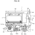
- FIG. 20 to FIG. 22 each are a diagram for explaining the cooling mechanism for microwave generator 3 and fan drive unit 16 , and these diagrams each illustrate a flow of cooling air by the cooling mechanism.
- FIG. 20 to FIG. 22 each illustrate exposed cavity 2 while components other than front surface 1 a of body 1 are omitted for explanation.
- FIG. 23 is an enlarged view of A part of FIG. 4
- FIG. 24 is an enlarged view of E part of FIG. 21 .
- cooling unit 5 when cooling unit 5 is operated, air is sucked from front grill 31 a of machine chamber 31 (refer to arrow W 1 ), and the air is sent out toward a back side of cooling unit 5 (refer to arrow W 2 ). The air sent out cools inverter unit 4 and microwave generator 3 in order.
- exhaust duct 45 (refer to FIG. 5A ) disposed on a rear surface of body 1 and is then discharged above heating cooker 30 (refer to arrow W 3 ).
- FIG. 21 and FIG. 22 illustration of exhaust duct 45 is omitted.
- exhaust holes 37 formed in inner upper surface 1 b and inner side surface 1 c (refer to FIG. 23 and FIG. 24 ) of front surface 1 a of body 1 is exhausted outside heating cooker 30 .
- Exhaust holes 37 are disposed so as to face an upper surface and a side surface of door 11 being closed.
- inverter unit 4 and microwave generator 3 are cooled by use of cooling unit 5 , and fan drive unit 16 is cooled by use of cooling fan 43 .
- inverter unit 4 and microwave generator 3 , and fan drive unit 16 are cooled by separate cooling flows, so that it is possible to attain efficient cooling.
- a temperature of microwave generator 3 becomes higher than a temperature of inverter unit 4 .
- inverter unit 4 and microwave generator 3 are cooled in order of a low temperature, so that it is possible to efficiently cool inverter unit 4 and microwave generator 3 .
- Cooling air constantly flows through an inner space of body 1 by cooling fan 43 , and therefore an effect of reducing a surface temperature of an upper surface and a front surface of heating cooker 30 (an upper surface and front surface 1 a of body 1 ) is also exerted.
- exhaust holes 37 hits on the upper surface and the side surface of door 11 . Consequently, unlike a case where exhaust holes 37 is formed in, for example, front surface 1 a of body 1 , air discharged from exhaust holes 37 is unlikely to directly hit on a user, and therefore it is possible to reduce uncomfortable feeling of the user.
- a number of exhaust holes 37 a disposed at a central part is less than a number of exhaust holes 37 b disposed right and left of the central part. Thus, exhaust volume from the central part is decreased.
- Exhaust holes 37 c is also provided in inner side surface 1 c in addition to exhaust holes 37 a , 37 b , and hot air to be exhausted is dispersed, so that it is possible to further reduce the uncomfortable feeling of the user.
- Front grill 31 a is provided on a front surface of heating cooker 30 , and therefore it is possible to reliably suck air regardless of whether other object exists adjacent to right and left. Consequently, for example, even in a case where a plurality of heating cookers 30 are disposed right and left adjacent to each other, it is possible to ensure a suction path of cooling air.
- microwave generator 3 microwave generator 3 (magnetrons 3 a , 3 b ) are disposed below convection device 35 , cooling unit 5 (cooling fans 5 a to 5 d ) and inverter unit 4 (inverters 4 a , 4 b ) are disposed below cavity 2 .
- a group of magnetron 3 a and waveguide 17 a , and a group of magnetron 3 b and waveguide 17 b are disposed right and left, respectively, and waveguides 17 a , 17 b are disposed so as to extend in the front-back direction.
- Inverter 4 a is disposed below waveguide 17 a so as to be aligned with magnetron 3 a in the front-back direction.
- Inverter 4 b is disposed below waveguide 17 b so as to be aligned with magnetron 3 b in the front-back direction.
- Cooling fans 5 a to 5 d are disposed so as to be aligned with inverters 4 a , 4 b in the front-back direction and are disposed such that the respective rotating shafts of the fans are aligned on a straight line.
- heating cooker 30 including a plurality of magnetrons can be designed much smaller.
- a plurality of heating cookers are often installed adjacent to each other in a right-left direction. This effect is particularly meaningful for a microwave oven for business use.
- FIG. 25 is a side view of the inside of body 1 with door 11 closed (door 11 is not illustrated).
- FIG. 26 and FIG. 27A each are a perspective view of the inside of body 1 with door 11 closed (door 11 is not illustrated).
- FIG. 27B is an enlarged view of G part surrounded by one dot chain line in FIG. 27A .
- FIG. 28A is a sectional view taken along line 28 A- 28 A of FIG. 25 .
- FIG. 28B is an enlarged view of H part surrounded by one dot chain line in FIG. 28A .
- FIG. 29 is a side view of the inside of body 1 with door 11 opened.
- Hinge structures 60 each include hinge 61 , door hinge spacer 62 , hinge mounting plate 63 , door guide roller 64 , door arm 65 , and spring 66 .
- hinge 61 penetrates front surface 2 a of cavity 2 , is fixed to door hinge spacer 62 , and rotatably supports a lower end part of door 11 .
- hinge 61 , hinge mounting plate 63 , and spring 66 are mounted on door hinge spacer 62 .
- hook 62 a for hooking spring 66 is provided.
- Hinge mounting plate 63 is fixed to door hinge spacer 62 and bottom surface 2 c of cavity 2
- hinge 61 is fixed to bottom surface 2 c of cavity 2 through door hinge spacer 62 .
- Door guide roller 64 supports sliding in the front-back direction of door arm 65 .
- Door arm 65 has a first end mounted on a central part of door 11 , and a second end mounted on a first end of spring 66 , and supports opening/closing of door 11 along with hinge 61 .
- a second end of spring 66 is fixed to hook 62 a of door hinge spacer 62 .
- spring 66 contracts (refer to FIG. 25 ).
- spring 66 extends (refer to FIG. 29 ).
- door 11 shifts from a closed state to an opened state (refer to FIG. 25 to FIG. 29 ) by rotating around the lower end part, which is a connection point with hinges 61 , in a longitudinal direction.
- door arms 65 connected to the central part of door 11 move forward while sliding on door guide rollers 64 .
- Springs 66 mounted on the second ends of door arm 65 are brought into an elongated state from a contracted state by the movement of door arms 65 .
- hinge structures 60 By such operation of hinge structures 60 , door 11 is opened. On the contrary, when door 11 shifts from the opened state to the closed state (refer to FIG. 29 to FIG. 25 ), reverse operation to the above operation is performed.
- hinge structures 60 including hinges 61 are mounted on bottom surface 2 c of cavity 2 by hinge mounting plates 63 .
- hinge mounting plates 63 Unlike this, in a case of a configuration in which hinges 61 are mounted not on cavity 2 but on body 1 , a difference between a temperature of hinges 61 and a temperature of front surface 2 a of cavity 2 is increased. Therefore, when door 11 is closed, a gap between door 11 mounted on hinges 61 and front surface 2 a of cavity 2 may be generated by a difference in a coefficient of thermal expansion.
- hinges 61 are mounted on bottom surface 2 c of cavity 2 , and therefore a temperature difference between hinge 61 and front surface 2 a of cavity 2 is reduced. Consequently, it is possible to reduce a possibility that a gap is generated between door 11 and front surface 2 a of cavity 2 when door 11 is closed.
- waveguides 17 a , 17 b linearly extend forward from magnetrons 3 a , 3 b.
- waveguides 40 a and waveguides 40 b may have H corner shape 39 c and H corner shape 39 d curved toward microwave radiation hole 39 a and microwave radiation hole 39 b at 90 degrees, respectively.
- E corner shape is a shape in which a waveguide is bent in parallel to an electric field surface (E surface)
- H corner shape is a shape in which each waveguides 40 a , 40 b is bent in parallel to a magnetic field surface (H surface).
- Waveguides 40 a , 40 b are connected to microwave radiation holes 39 a , 39 b at H corner shapes 39 c , 39 d , so that microwaves whose advancing directions are bent at 90 degrees overlap with each other in a vicinity of a central part of cavity 2 ; therefore, it is possible to radiate microwaves having higher intensity.
- FIG. 31 is a perspective view of convection device 50 according to the second exemplary embodiment.
- FIG. 32 is a front view of back wall 2 d of cavity 2 according to the second exemplary embodiment of the present disclosure.
- convection device 50 for generating hot air to be supplied into cavity 2 is provided behind back wall 2 d of cavity 2 also in this exemplary embodiment. Convection device 50 is partitioned from cavity 2 by back wall 2 d , and is communicated with cavity 2 through openings 22 .
- upper and lower positional relation of joining part 19 c and isolated part 19 d of air guide 19 is reversed to upper and lower positional relation of the joining part and the isolated part in the first exemplary embodiment. That is, isolated part 19 d of air guide 19 is provided so as to be isolated from air guide 18 in an upper half of air guide 18 .
- discharge ports 22 d are provided above suction ports 22 c formed at a substantially central part of back wall 2 d (refer to FIG. 32 ) in this exemplary embodiment.
- air guide 19 is formed by a separate member from air guide 18 in the first exemplary embodiment, joining part 19 c of air guide 19 is formed integrally with air guide 18 in this exemplary embodiment.
- wind direction plates 20 , 21 are provided in the front-back direction between air guide 18 and air guide 19 in the first exemplary embodiment
- a single wind direction plate is provided in the front-back direction between air guide 18 and air guide 19 in this exemplary embodiment.
- Wind direction plate 23 partitions a space between air guide 18 and isolated part 19 d of air guide 19 , and directs forward hot air spirally sent out by circulation fan 14 , similarly to wind direction plates 20 , 21 .
- the air sent out by circulation fan 14 is guided to air guide 19 , and flows through the space formed between air guide 18 and isolated part 19 d of air guide 19 (arrows D 4 , D 5 ). Thereafter, the air is sent out to a vicinity of a ceiling of cavity 2 through discharge ports 22 b of back wall 2 d.
- FIG. 33 is a perspective view illustrating an inside of cavity 2 , particularly the ceiling according to the second exemplary embodiment.
- wind direction plate 24 protruding forward is provided in a vicinity of a borderline between suction ports 22 c and discharge ports 22 d of back wall 2 d .
- Wind direction plate 24 has horizontal portion 24 a horizontally extending across cavity 2 in a right-left direction, and vertical portion 24 b and vertical portion 24 c formed above horizontal portion 24 a , and vertically extending at a predetermined interval.
- Wind direction plate 24 imparts directivity to a flow of air supplied from convection device 35 into cavity 2 , and directs most of the flow of the air toward grill heater 10 .
- wind direction plates 25 , 26 Two wind direction plates (wind direction plates 25 , 26 ) extending in a right-left direction are provided on ceiling 2 b of cavity 2 so as to be located in a vicinity of grill heater 10 (more specifically, surrounded by bent grill heater 10 ).
- a width of wind direction plate 26 is wider than a width of wind direction plate 25 located behind wind direction plate 26 .
- Wind direction plates 25 , 26 direct a portion of the flow of the air sent out from convection device 35 downward, in a vicinity of a center of the ceiling of cavity 2 .
- the present disclosure is applicable to a microwave oven having a grill mode and a convection mode, and particularly useful for a microwave oven for business use used in a convenience store, a fast food restaurant, or the like.
Landscapes
- Physics & Mathematics (AREA)
- Electromagnetism (AREA)
- Thermal Sciences (AREA)
- Electric Ovens (AREA)
- Constitution Of High-Frequency Heating (AREA)
Applications Claiming Priority (3)
| Application Number | Priority Date | Filing Date | Title |
|---|---|---|---|
| JP2014-020431 | 2014-02-05 | ||
| JP2014020431 | 2014-02-05 | ||
| PCT/JP2015/000510 WO2015118868A1 (ja) | 2014-02-05 | 2015-02-05 | マイクロ波加熱装置 |
Publications (2)
| Publication Number | Publication Date |
|---|---|
| US20160330800A1 US20160330800A1 (en) | 2016-11-10 |
| US10609772B2 true US10609772B2 (en) | 2020-03-31 |
Family
ID=53777680
Family Applications (1)
| Application Number | Title | Priority Date | Filing Date |
|---|---|---|---|
| US15/110,567 Active 2036-05-22 US10609772B2 (en) | 2014-02-05 | 2015-02-05 | Microwave heating device |
Country Status (5)
| Country | Link |
|---|---|
| US (1) | US10609772B2 (ja) |
| EP (1) | EP3104667B1 (ja) |
| JP (1) | JP6402367B2 (ja) |
| CN (1) | CN105960830B (ja) |
| WO (1) | WO2015118868A1 (ja) |
Families Citing this family (5)
| Publication number | Priority date | Publication date | Assignee | Title |
|---|---|---|---|---|
| US10904959B2 (en) * | 2016-11-30 | 2021-01-26 | Illinois Tool Works, Inc. | Apparatus and system for solid state oven electronics cooling |
| US10764971B2 (en) * | 2016-11-30 | 2020-09-01 | Illinois Tool Works, Inc. | Waveguide assembly for an RF oven |
| JP6986684B2 (ja) * | 2018-02-28 | 2021-12-22 | パナソニックIpマネジメント株式会社 | 高周波加熱装置 |
| DE102019201332A1 (de) * | 2019-02-01 | 2020-08-06 | BSH Hausgeräte GmbH | Haushalts-Gargerät und Verfahren zum Betreiben eines Haushalts-Gargeräts |
| JP7398950B2 (ja) * | 2019-12-25 | 2023-12-15 | シャープ株式会社 | 加熱調理器 |
Citations (14)
| Publication number | Priority date | Publication date | Assignee | Title |
|---|---|---|---|---|
| JPS5340428A (en) | 1976-09-25 | 1978-04-13 | Matsushita Electric Ind Co Ltd | High frequency heater |
| JPS54162245A (en) | 1978-06-13 | 1979-12-22 | Matsushita Electric Ind Co Ltd | High-frequency heating device |
| US5166487A (en) | 1989-12-15 | 1992-11-24 | Tecogen, Inc. | Cooking oven with convection and microwave heating |
| US5245149A (en) * | 1990-06-21 | 1993-09-14 | Immobiliare Centro Nord S.P.A. | Process and device for accelerating the drying of cement mixes |
| JPH05326132A (ja) | 1992-05-22 | 1993-12-10 | Matsushita Electric Ind Co Ltd | 高周波加熱装置 |
| US5483044A (en) * | 1993-06-25 | 1996-01-09 | Merrychef Limited | Microwave heating with hot and cold air streams |
| JP2740411B2 (ja) | 1992-05-25 | 1998-04-15 | 三洋電機株式会社 | 電子レンジ |
| JP2001319766A (ja) | 2000-05-11 | 2001-11-16 | Sharp Corp | 高周波加熱装置 |
| JP2003074872A (ja) | 2001-09-05 | 2003-03-12 | Sanyo Electric Co Ltd | 高周波加熱調理器 |
| JP2005241241A (ja) | 2005-03-18 | 2005-09-08 | Sanyo Electric Co Ltd | 高周波加熱調理器 |
| US20110147376A1 (en) * | 2008-08-29 | 2011-06-23 | Shinya Ueda | Cooking device |
| US9131541B2 (en) * | 2010-12-21 | 2015-09-08 | Whirlpool Corporation | Methods of controlling cooling in a microwave heating apparatus and apparatus thereof |
| US9363854B2 (en) * | 2009-06-19 | 2016-06-07 | Lg Electronics Inc. | Cooking apparatus using microwaves |
| US9674903B2 (en) * | 2010-05-26 | 2017-06-06 | Lg Electronics Inc. | Cooking apparatus and operating method thereof |
-
2015
- 2015-02-05 US US15/110,567 patent/US10609772B2/en active Active
- 2015-02-05 CN CN201580006756.XA patent/CN105960830B/zh active Active
- 2015-02-05 WO PCT/JP2015/000510 patent/WO2015118868A1/ja active Application Filing
- 2015-02-05 JP JP2015561221A patent/JP6402367B2/ja active Active
- 2015-02-05 EP EP15746895.0A patent/EP3104667B1/en active Active
Patent Citations (16)
| Publication number | Priority date | Publication date | Assignee | Title |
|---|---|---|---|---|
| JPS5340428A (en) | 1976-09-25 | 1978-04-13 | Matsushita Electric Ind Co Ltd | High frequency heater |
| JPS54162245A (en) | 1978-06-13 | 1979-12-22 | Matsushita Electric Ind Co Ltd | High-frequency heating device |
| FR2428955A1 (fr) | 1978-06-13 | 1980-01-11 | Bosch Siemens Hausgeraete | Appareil de chauffage du type a micro-ondes |
| US4314126A (en) | 1978-06-13 | 1982-02-02 | Matsushita Electric Industrial Co., Ltd. | Microwave heating apparatus with cooling conduit |
| US5166487A (en) | 1989-12-15 | 1992-11-24 | Tecogen, Inc. | Cooking oven with convection and microwave heating |
| US5245149A (en) * | 1990-06-21 | 1993-09-14 | Immobiliare Centro Nord S.P.A. | Process and device for accelerating the drying of cement mixes |
| JPH05326132A (ja) | 1992-05-22 | 1993-12-10 | Matsushita Electric Ind Co Ltd | 高周波加熱装置 |
| JP2740411B2 (ja) | 1992-05-25 | 1998-04-15 | 三洋電機株式会社 | 電子レンジ |
| US5483044A (en) * | 1993-06-25 | 1996-01-09 | Merrychef Limited | Microwave heating with hot and cold air streams |
| JP2001319766A (ja) | 2000-05-11 | 2001-11-16 | Sharp Corp | 高周波加熱装置 |
| JP2003074872A (ja) | 2001-09-05 | 2003-03-12 | Sanyo Electric Co Ltd | 高周波加熱調理器 |
| JP2005241241A (ja) | 2005-03-18 | 2005-09-08 | Sanyo Electric Co Ltd | 高周波加熱調理器 |
| US20110147376A1 (en) * | 2008-08-29 | 2011-06-23 | Shinya Ueda | Cooking device |
| US9363854B2 (en) * | 2009-06-19 | 2016-06-07 | Lg Electronics Inc. | Cooking apparatus using microwaves |
| US9674903B2 (en) * | 2010-05-26 | 2017-06-06 | Lg Electronics Inc. | Cooking apparatus and operating method thereof |
| US9131541B2 (en) * | 2010-12-21 | 2015-09-08 | Whirlpool Corporation | Methods of controlling cooling in a microwave heating apparatus and apparatus thereof |
Non-Patent Citations (2)
| Title |
|---|
| Extended Search Report in corresponding European Application No. 15746895.0, dated Dec. 21, 2016, 9 pages. |
| International Search Report of PCT application No. PCT/JP2015/000510 dated Apr. 7, 2015. |
Also Published As
| Publication number | Publication date |
|---|---|
| JP6402367B2 (ja) | 2018-10-10 |
| EP3104667A4 (en) | 2017-01-18 |
| WO2015118868A1 (ja) | 2015-08-13 |
| CN105960830A (zh) | 2016-09-21 |
| CN105960830B (zh) | 2019-07-26 |
| JPWO2015118868A1 (ja) | 2017-03-23 |
| EP3104667A1 (en) | 2016-12-14 |
| EP3104667B1 (en) | 2019-10-02 |
| US20160330800A1 (en) | 2016-11-10 |
Similar Documents
| Publication | Publication Date | Title |
|---|---|---|
| US10368403B2 (en) | Heating cooker | |
| US10609772B2 (en) | Microwave heating device | |
| US8950319B2 (en) | Cooking appliance | |
| JP6898140B2 (ja) | 加熱調理器 | |
| JP6837193B2 (ja) | 加熱調理器 | |
| US10697643B2 (en) | Cooker | |
| KR100395559B1 (ko) | 히터를 가지는 전자렌지 | |
| JP6491973B2 (ja) | 加熱調理器 | |
| CN220713697U (zh) | 烹饪设备 | |
| JP6114920B2 (ja) | 加熱調理器 | |
| KR20080005014U (ko) | 조리장치 | |
| JP2010181117A (ja) | 加熱調理器 | |
| JP2011080710A (ja) | 加熱装置 | |
| KR100789831B1 (ko) | 전기 오븐 | |
| KR101760942B1 (ko) | 조리기기 | |
| KR101175734B1 (ko) | 오븐 | |
| JP5693356B2 (ja) | 加熱調理器 | |
| KR20120033426A (ko) | 조리기기 | |
| KR20120033424A (ko) | 조리기기 | |
| KR20120033428A (ko) | 조리기기 | |
| JP2015203518A (ja) | 加熱調理器 | |
| JP2010107083A (ja) | 加熱調理器 |
Legal Events
| Date | Code | Title | Description |
|---|---|---|---|
| AS | Assignment |
Owner name: PANASONIC INTELLECTUAL PROPERTY MANAGEMENT CO., LTD., JAPAN Free format text: ASSIGNMENT OF ASSIGNORS INTEREST;ASSIGNORS:HAYASHI, TAKAHIRO;OTSUKI, YUICHI;YAMASHITA, SEIICHI;AND OTHERS;SIGNING DATES FROM 20160617 TO 20160620;REEL/FRAME:039162/0710 Owner name: PANASONIC INTELLECTUAL PROPERTY MANAGEMENT CO., LT Free format text: ASSIGNMENT OF ASSIGNORS INTEREST;ASSIGNORS:HAYASHI, TAKAHIRO;OTSUKI, YUICHI;YAMASHITA, SEIICHI;AND OTHERS;SIGNING DATES FROM 20160617 TO 20160620;REEL/FRAME:039162/0710 |
|
| STPP | Information on status: patent application and granting procedure in general |
Free format text: RESPONSE TO NON-FINAL OFFICE ACTION ENTERED AND FORWARDED TO EXAMINER |
|
| STPP | Information on status: patent application and granting procedure in general |
Free format text: FINAL REJECTION MAILED |
|
| STPP | Information on status: patent application and granting procedure in general |
Free format text: RESPONSE AFTER FINAL ACTION FORWARDED TO EXAMINER |
|
| STPP | Information on status: patent application and granting procedure in general |
Free format text: DOCKETED NEW CASE - READY FOR EXAMINATION |
|
| STPP | Information on status: patent application and granting procedure in general |
Free format text: NOTICE OF ALLOWANCE MAILED -- APPLICATION RECEIVED IN OFFICE OF PUBLICATIONS |
|
| STPP | Information on status: patent application and granting procedure in general |
Free format text: PUBLICATIONS -- ISSUE FEE PAYMENT RECEIVED |
|
| STPP | Information on status: patent application and granting procedure in general |
Free format text: PUBLICATIONS -- ISSUE FEE PAYMENT VERIFIED |
|
| STCF | Information on status: patent grant |
Free format text: PATENTED CASE |
|
| MAFP | Maintenance fee payment |
Free format text: PAYMENT OF MAINTENANCE FEE, 4TH YEAR, LARGE ENTITY (ORIGINAL EVENT CODE: M1551); ENTITY STATUS OF PATENT OWNER: LARGE ENTITY Year of fee payment: 4 |