US10596741B2 - Blown film extrusion device and method for controlling the temperature - Google Patents
Blown film extrusion device and method for controlling the temperature Download PDFInfo
- Publication number
- US10596741B2 US10596741B2 US14/906,878 US201414906878A US10596741B2 US 10596741 B2 US10596741 B2 US 10596741B2 US 201414906878 A US201414906878 A US 201414906878A US 10596741 B2 US10596741 B2 US 10596741B2
- Authority
- US
- United States
- Prior art keywords
- blow head
- blown film
- air gap
- extrusion device
- ambient air
- Prior art date
- Legal status (The legal status is an assumption and is not a legal conclusion. Google has not performed a legal analysis and makes no representation as to the accuracy of the status listed.)
- Active, expires
Links
Images


Classifications
-
- B—PERFORMING OPERATIONS; TRANSPORTING
- B29—WORKING OF PLASTICS; WORKING OF SUBSTANCES IN A PLASTIC STATE IN GENERAL
- B29C—SHAPING OR JOINING OF PLASTICS; SHAPING OF MATERIAL IN A PLASTIC STATE, NOT OTHERWISE PROVIDED FOR; AFTER-TREATMENT OF THE SHAPED PRODUCTS, e.g. REPAIRING
- B29C48/00—Extrusion moulding, i.e. expressing the moulding material through a die or nozzle which imparts the desired form; Apparatus therefor
- B29C48/25—Component parts, details or accessories; Auxiliary operations
- B29C48/78—Thermal treatment of the extrusion moulding material or of preformed parts or layers, e.g. by heating or cooling
- B29C48/86—Thermal treatment of the extrusion moulding material or of preformed parts or layers, e.g. by heating or cooling at the nozzle zone
-
- B—PERFORMING OPERATIONS; TRANSPORTING
- B29—WORKING OF PLASTICS; WORKING OF SUBSTANCES IN A PLASTIC STATE IN GENERAL
- B29C—SHAPING OR JOINING OF PLASTICS; SHAPING OF MATERIAL IN A PLASTIC STATE, NOT OTHERWISE PROVIDED FOR; AFTER-TREATMENT OF THE SHAPED PRODUCTS, e.g. REPAIRING
- B29C48/00—Extrusion moulding, i.e. expressing the moulding material through a die or nozzle which imparts the desired form; Apparatus therefor
- B29C48/25—Component parts, details or accessories; Auxiliary operations
- B29C48/30—Extrusion nozzles or dies
- B29C48/32—Extrusion nozzles or dies with annular openings, e.g. for forming tubular articles
-
- B—PERFORMING OPERATIONS; TRANSPORTING
- B29—WORKING OF PLASTICS; WORKING OF SUBSTANCES IN A PLASTIC STATE IN GENERAL
- B29C—SHAPING OR JOINING OF PLASTICS; SHAPING OF MATERIAL IN A PLASTIC STATE, NOT OTHERWISE PROVIDED FOR; AFTER-TREATMENT OF THE SHAPED PRODUCTS, e.g. REPAIRING
- B29C48/00—Extrusion moulding, i.e. expressing the moulding material through a die or nozzle which imparts the desired form; Apparatus therefor
- B29C48/25—Component parts, details or accessories; Auxiliary operations
- B29C48/78—Thermal treatment of the extrusion moulding material or of preformed parts or layers, e.g. by heating or cooling
- B29C48/86—Thermal treatment of the extrusion moulding material or of preformed parts or layers, e.g. by heating or cooling at the nozzle zone
- B29C48/865—Heating
-
- B—PERFORMING OPERATIONS; TRANSPORTING
- B29—WORKING OF PLASTICS; WORKING OF SUBSTANCES IN A PLASTIC STATE IN GENERAL
- B29C—SHAPING OR JOINING OF PLASTICS; SHAPING OF MATERIAL IN A PLASTIC STATE, NOT OTHERWISE PROVIDED FOR; AFTER-TREATMENT OF THE SHAPED PRODUCTS, e.g. REPAIRING
- B29C48/00—Extrusion moulding, i.e. expressing the moulding material through a die or nozzle which imparts the desired form; Apparatus therefor
- B29C48/25—Component parts, details or accessories; Auxiliary operations
- B29C48/78—Thermal treatment of the extrusion moulding material or of preformed parts or layers, e.g. by heating or cooling
- B29C48/86—Thermal treatment of the extrusion moulding material or of preformed parts or layers, e.g. by heating or cooling at the nozzle zone
- B29C48/87—Cooling
-
- B—PERFORMING OPERATIONS; TRANSPORTING
- B29—WORKING OF PLASTICS; WORKING OF SUBSTANCES IN A PLASTIC STATE IN GENERAL
- B29C—SHAPING OR JOINING OF PLASTICS; SHAPING OF MATERIAL IN A PLASTIC STATE, NOT OTHERWISE PROVIDED FOR; AFTER-TREATMENT OF THE SHAPED PRODUCTS, e.g. REPAIRING
- B29C48/00—Extrusion moulding, i.e. expressing the moulding material through a die or nozzle which imparts the desired form; Apparatus therefor
- B29C48/25—Component parts, details or accessories; Auxiliary operations
- B29C48/92—Measuring, controlling or regulating
-
- B—PERFORMING OPERATIONS; TRANSPORTING
- B29—WORKING OF PLASTICS; WORKING OF SUBSTANCES IN A PLASTIC STATE IN GENERAL
- B29C—SHAPING OR JOINING OF PLASTICS; SHAPING OF MATERIAL IN A PLASTIC STATE, NOT OTHERWISE PROVIDED FOR; AFTER-TREATMENT OF THE SHAPED PRODUCTS, e.g. REPAIRING
- B29C2948/00—Indexing scheme relating to extrusion moulding
- B29C2948/92—Measuring, controlling or regulating
- B29C2948/92504—Controlled parameter
- B29C2948/9258—Velocity
- B29C2948/926—Flow or feed rate
-
- B—PERFORMING OPERATIONS; TRANSPORTING
- B29—WORKING OF PLASTICS; WORKING OF SUBSTANCES IN A PLASTIC STATE IN GENERAL
- B29C—SHAPING OR JOINING OF PLASTICS; SHAPING OF MATERIAL IN A PLASTIC STATE, NOT OTHERWISE PROVIDED FOR; AFTER-TREATMENT OF THE SHAPED PRODUCTS, e.g. REPAIRING
- B29C2948/00—Indexing scheme relating to extrusion moulding
- B29C2948/92—Measuring, controlling or regulating
- B29C2948/92504—Controlled parameter
- B29C2948/92704—Temperature
-
- B—PERFORMING OPERATIONS; TRANSPORTING
- B29—WORKING OF PLASTICS; WORKING OF SUBSTANCES IN A PLASTIC STATE IN GENERAL
- B29C—SHAPING OR JOINING OF PLASTICS; SHAPING OF MATERIAL IN A PLASTIC STATE, NOT OTHERWISE PROVIDED FOR; AFTER-TREATMENT OF THE SHAPED PRODUCTS, e.g. REPAIRING
- B29C48/00—Extrusion moulding, i.e. expressing the moulding material through a die or nozzle which imparts the desired form; Apparatus therefor
- B29C48/001—Combinations of extrusion moulding with other shaping operations
- B29C48/0018—Combinations of extrusion moulding with other shaping operations combined with shaping by orienting, stretching or shrinking, e.g. film blowing
-
- B—PERFORMING OPERATIONS; TRANSPORTING
- B29—WORKING OF PLASTICS; WORKING OF SUBSTANCES IN A PLASTIC STATE IN GENERAL
- B29C—SHAPING OR JOINING OF PLASTICS; SHAPING OF MATERIAL IN A PLASTIC STATE, NOT OTHERWISE PROVIDED FOR; AFTER-TREATMENT OF THE SHAPED PRODUCTS, e.g. REPAIRING
- B29C48/00—Extrusion moulding, i.e. expressing the moulding material through a die or nozzle which imparts the desired form; Apparatus therefor
- B29C48/03—Extrusion moulding, i.e. expressing the moulding material through a die or nozzle which imparts the desired form; Apparatus therefor characterised by the shape of the extruded material at extrusion
- B29C48/09—Articles with cross-sections having partially or fully enclosed cavities, e.g. pipes or channels
- B29C48/10—Articles with cross-sections having partially or fully enclosed cavities, e.g. pipes or channels flexible, e.g. blown foils
-
- B—PERFORMING OPERATIONS; TRANSPORTING
- B29—WORKING OF PLASTICS; WORKING OF SUBSTANCES IN A PLASTIC STATE IN GENERAL
- B29C—SHAPING OR JOINING OF PLASTICS; SHAPING OF MATERIAL IN A PLASTIC STATE, NOT OTHERWISE PROVIDED FOR; AFTER-TREATMENT OF THE SHAPED PRODUCTS, e.g. REPAIRING
- B29C49/00—Blow-moulding, i.e. blowing a preform or parison to a desired shape within a mould; Apparatus therefor
- B29C49/02—Combined blow-moulding and manufacture of the preform or the parison
- B29C49/04—Extrusion blow-moulding
-
- B—PERFORMING OPERATIONS; TRANSPORTING
- B29—WORKING OF PLASTICS; WORKING OF SUBSTANCES IN A PLASTIC STATE IN GENERAL
- B29L—INDEXING SCHEME ASSOCIATED WITH SUBCLASS B29C, RELATING TO PARTICULAR ARTICLES
- B29L2007/00—Flat articles, e.g. films or sheets
- B29L2007/008—Wide strips, e.g. films, webs
Definitions
- the present invention relates to a blown film extrusion device, a temperature controller for a blown film extrusion device and a method for controlling the temperature of a blown film extrusion device.
- annular tube is configured in a thermoplastic melt prepared by an extruder via a blown film extrusion device, which is laid flat via an extractor device and is coiled on a roller to form roles in a usable dimension.
- the tube preparation is achieved in that in the blown film extrusion device a blow head with an annular nozzle gap is intended from which the melt escapes during the extractor process supported by an outer and inner air stream and is blown to the desired format.
- the outer ambient air stream and also the inner air stream are cooled down, whereby the melt reaches the so called freezing limit (freeze area) and the desired tube dimensions are fixed with extent and thickness.
- the blow head has to be kept in a certain temperature in the areas of the melting ducts with heating capacities of some kW to 100 kW, which corresponds to the temperature of the thermoplastic melt.
- heat insulating hoods are known for example from DE 1 729 129 A1, which insulate the blow head in respect to the outer ambient air.
- Object of the invention is to improve the heating of the blow head of a blown film extrusion device.
- This object is solved by a blow head extrusion device, a temperature control and a method for controlling the temperature.
- the blown film extrusion device comprises a blow head and an insulation, which comprises a thermal resistance for thermal insulation of the blow head in respect to the outer ambient air, wherein the blown film extrusion device comprises elements for controlling the thermal resistance.
- the thermal resistance can be selectively altered in relation to the outer ambient air, wherein the control can basically occur manually (for example by using a control lever) and/or automatically.
- the control can basically occur manually (for example by using a control lever) and/or automatically.
- a faster exchange of the thermal resistance can be achieved, which increases the temperature control of the whole blow head, namely during the heating process (for example during the start of the whole unit) and also during the cooling process (for example during the shutdown of the whole unit).
- the thermal resistance comprises means for thermal separation.
- This can be gaseous and also solid media.
- the means for thermal separation can comprise at least an air gap.
- the thermal resistance of the at least one air gap can be controlled in a way that the air stream is influenced in the at least one air gap.
- a blower with electrically controllable blower performance can be intended.
- the flaps shield the air gap from the outer ambient air.
- the flaps enable a circulation with the outer ambient air by convection and/or by thermal radiation and/or by an air stream produced by a blower.
- the flaps are connected to one another with a gear. In this manner it is possible that all present flaps can be operated by an operator at the same time using one single control lever. Alternatively and/or additionally it is possible that the flaps can be controlled in a motor-driven manner in a separate manner or together via the gear.
- the elements for controlling the thermal resistance comprise at least one flap, which can be movably mounted between an insulation position closing the air gap and a cooling position opening the air gap.
- the actuation of the cooling or the cooling itself can occur passively and/or actively. Is the flap opened and therewith in the cooling position, it is possible that at least by a convection heat can be removed from the air gap and therewith from the blow head.
- This convection can additionally or alternatively be configured positively driven by a blower. According to the assembly and size of the respective flap in the opened cooling position further thermal radiation can escape from the blow head through the opening which is released by the flap in the open position.
- the heat resistance in the at least one air gap can be controlled in a way that a low pressure or a vacuum is generated in the air gap according to the principal of a thermos flask.
- the means for thermal separation comprise a solid insulating material particularly ceramic, which can be incorporated within the insulation gap.
- the elements for controlling the thermal resistance can thereby influence the position of the solid insulation material within the insulation gap. While in a position the solid insulation material generates a high thermal resistance in relation to the outer ambient air, the thermal resistance can be decreased when the solid insulation material is transferred in another position.
- the position of the solid insulation material is thereby controllable in a motor-driven manner.
- the means for thermal separation comprise a layer with pipes flown through with oil, wherein the oil is tempered to the desired temperature in an external tempering unit by heating or cooling.
- the means for thermal separation comprise a layer with Peltier elements.
- a Peltier element is an electric thermal transformer, which generates a temperature difference based on the Peltier effect during a current flow or which generates a current flow (Seebeck effect) during temperature differences.
- Peltier elements can hereby be used for cooling and also—during an inversion of the current direction—for heating.
- the temperature regulation according to the invention for the blown film extrusion device comprises a first control signal for controlling the heat performance of a heater integrated in the blow head and a second control signal for controlling the elements for controlling the heat resistance.
- the temperature regulation during shutdown of the unit is aligned in a way that the heat resistance can be altered to a particularly low value in order to enable a possibly fast cooling down of the blow head.
- the temperature regulation during the operation is aligned in a manner that the controllable heat resistance can serve as a further variable beneath the blow head heater for regulating the blow head temperature.
- the temperature of the blow head can be reduced rapidly during the operation as soon as due to the high melting temperature the blow head tends to overheat or the blow head temperature has to be reduced due to other method related reasons.
- FIG. 1 a first embodiment of a blown film extrusion device according to the invention
- FIG. 2 the embodiment of FIG. 1 with the elements in a cooling position
- FIG. 3 a further embodiment of a blown film extrusion device according to the invention
- FIG. 4 the embodiment of FIG. 3 with the cooling flaps in a cooling position
- FIG. 5 a further embodiment of a blow head extrusion device according to the invention
- FIG. 6 the embodiment of FIG. 5 with the cooling flap in a cooling position
- FIG. 7 a further embodiment of a blown film extrusion device according to the invention.
- FIG. 8 the embodiment of FIG. 7 with the cooling flap in a cooling position
- FIG. 9 a further embodiment of the blown film extrusion device according to the invention.
- FIG. 10 an embodiment of an insulation according to the invention
- FIG. 11 a further embodiment of a cooling flap
- FIG. 12 the embodiment of FIG. 11 with the cooling flap in a cooling position.
- FIGS. 1 and 2 show a first embodiment of a blown film extrusion device 10 according to the invention. This is assembled about a blow head 100 , wherein hereby a carrier structure 30 , not described in detail, generates the assembly in a shown manner. Thereby, an insulating gap 40 is configured between the insulation 20 and the blow head 100 .
- the FIG. 1 shows single elements 22 for controlling the heat resistance in form of cooling flaps 24 in the insulating position IP while FIG. 2 shows all cooling flaps 24 in the cooling position KP. With this embodiment the cooling occurs by heat convection and heat radiation.
- FIGS. 3 and 4 schematically show a cross section of the embodiment of FIG. 1 and FIG. 2 .
- the blow head 100 and the elements 22 configured as cooling flaps 24 are shown in a schematic cross section.
- the heat convection KO and the heat radiation ST are shown in the cooling gap 40 . If by flapping of the cooling flaps 24 the cooling flap 24 is moved from the insulating position IP into the cooling position KP according to FIG. 4 a heat exposure can occur by convection KO and heat radiation ST. Further, the axis of rotation or the opening axis 25 of the cooling flap 24 can be recognized.
- FIGS. 5 and 6 an embodiment of the cooling flaps 24 of the elements 22 can be recognized, which enable a stack effect.
- a first cooling flap 24 is assembled axially on the lower side and the second cooling flap 24 is assembled axially on the other side.
- a stack effect evolves which positively affects the heat exposure by convection.
- a blown device 50 is intended for support and for generating of a forced convection.
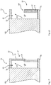
- FIGS. 7 and 8 show a further embodiment of a blown film extrusion device according to the invention.
- a telescopic structure of the cooling flap 24 of the element 22 is provided so that by an axial displacement of an outer cylinder sleeve relative to an inner cylinder sleeve a reduction of the axial extension of the insulation 20 is provided and therewith an opening is released. Therewith, again heat radiation ST and convection KO can escape from the blow head 100 or from the insulation gap 40 .
- FIG. 9 shows a further solution of a blown film extrusion device 10 according to the invention, by which within the insulation gap 40 single temperature devices 42 are assembled as possibilities for elements 22 within the insulation gap 40 .
- the elements can for example be heating bands flown through with temperate oil or electrically controlled Peltier elements.
- FIG. 10 schematically shows a possible sandwich structure of the insulation 20 , wherein within this insulation 20 an insulation material 26 is assembled.
- This is for example a so called aerogel mat.
- the inner side of the sandwich structure should be completely thermally separated from the outer side so that no heat bridges between the inner side and the outer side occur.
- FIGS. 11 and 12 show a further embodiment of a possible cooling flap 24 of the elements 22 .
- This is configured in two parts so that by opening via an opening axis 25 via a folding axis 23 a reduction of the geometric area extension of the cooling flaps 24 can occur.
- a possibly high opening cross sectional area is provided in order to achieve a possibly high cooling capacity.
Landscapes
- Engineering & Computer Science (AREA)
- Mechanical Engineering (AREA)
- Physics & Mathematics (AREA)
- Thermal Sciences (AREA)
- Manufacturing & Machinery (AREA)
- Extrusion Moulding Of Plastics Or The Like (AREA)
Applications Claiming Priority (4)
| Application Number | Priority Date | Filing Date | Title |
|---|---|---|---|
| DE102013108045.6 | 2013-07-26 | ||
| DE102013108045 | 2013-07-26 | ||
| DE102013108045.6A DE102013108045B9 (de) | 2013-07-26 | 2013-07-26 | Blasfolien-Extrusionsvorrichtung, Temperaturregelung für eine Blasfolien-Extrusionsvorrichtung und Verfahrenzur Temperaturregelung einer Blasfolien-Extrusionsvorrichtung |
| PCT/EP2014/061023 WO2015010811A1 (de) | 2013-07-26 | 2014-05-28 | Blasfolien-extrusionsvorrichtung und verfahren zur temperaturregelung |
Publications (2)
| Publication Number | Publication Date |
|---|---|
| US20160158990A1 US20160158990A1 (en) | 2016-06-09 |
| US10596741B2 true US10596741B2 (en) | 2020-03-24 |
Family
ID=50828911
Family Applications (1)
| Application Number | Title | Priority Date | Filing Date |
|---|---|---|---|
| US14/906,878 Active 2035-03-21 US10596741B2 (en) | 2013-07-26 | 2014-05-28 | Blown film extrusion device and method for controlling the temperature |
Country Status (5)
| Country | Link |
|---|---|
| US (1) | US10596741B2 (de) |
| EP (1) | EP3024631B1 (de) |
| CN (1) | CN105431276B (de) |
| DE (1) | DE102013108045B9 (de) |
| WO (1) | WO2015010811A1 (de) |
Cited By (1)
| Publication number | Priority date | Publication date | Assignee | Title |
|---|---|---|---|---|
| US11241817B2 (en) | 2016-01-15 | 2022-02-08 | Addex, Inc. | Controlled pressure enclosure |
Families Citing this family (3)
| Publication number | Priority date | Publication date | Assignee | Title |
|---|---|---|---|---|
| US11104054B2 (en) * | 2016-01-15 | 2021-08-31 | Addex, Inc. | High performance cooling system |
| US11298865B2 (en) * | 2016-01-15 | 2022-04-12 | Addex, Inc. | High performance cooling system |
| US11292176B2 (en) * | 2016-01-15 | 2022-04-05 | Addex, Inc. | High performance cooling system |
Citations (19)
| Publication number | Priority date | Publication date | Assignee | Title |
|---|---|---|---|---|
| DE6945123U (de) | 1968-12-04 | 1970-04-02 | Solvay | Extrusionskopf zur erzeugung von zellfoermigen polyolefinen |
| DE1729129A1 (de) | 1968-03-18 | 1971-06-09 | Windmoeller & Hoelscher | Folienblaskopf zur Herstellung von Schlauchfolien |
| US3650644A (en) * | 1967-02-10 | 1972-03-21 | Bemberg Ag | Apparatus for biaxially stretching thermoplastic tubular film |
| GB1396164A (en) | 1971-08-11 | 1975-06-04 | Basf Ag | Extruder die |
| DE2629789A1 (de) | 1976-07-02 | 1978-01-05 | Demag Kunststofftech | Blaskopf zur herstellung von schlauchfolien im extrusionsverfahren |
| EP0096179A2 (de) | 1982-06-07 | 1983-12-21 | Idemitsu Petrochemical Co. Ltd. | Mehrschichtenextruderdüse |
| JPS61254324A (ja) | 1985-05-07 | 1986-11-12 | Hajiika Kenkyusho:Kk | 押出成型方法 |
| US4895744A (en) * | 1986-06-26 | 1990-01-23 | General Electric Company | Method of making a multi-layer parison |
| DE4207439A1 (de) | 1991-12-12 | 1993-06-17 | Windmoeller & Hoelscher | Folienblaskopf zur herstellung von schlauchfolien aus thermoplastischem kunststoff |
| DE19644910A1 (de) | 1995-11-09 | 1997-05-15 | Barmag Barmer Maschf | Wärmeleitmantel mit gleichmäßiger Temperatur für Werkzeug, insbesondere zur Folienherstellung |
| US6065953A (en) * | 1997-05-28 | 2000-05-23 | Bentivoglio; Alfredo | Heated die lips system |
| US6238613B1 (en) * | 1999-07-14 | 2001-05-29 | Stratasys, Inc. | Apparatus and method for thermoplastic extrusion |
| US20060275523A1 (en) | 2005-06-02 | 2006-12-07 | Domenico Marzano | Distribution block for blown-film extrusion die |
| US20070098834A1 (en) * | 2004-10-12 | 2007-05-03 | Planeta Mirek | Air ring with circumferentially adjustable air flow |
| US20100040716A1 (en) * | 2008-08-13 | 2010-02-18 | Fridley Michael A | Thermally insulated die plate assembly for underwater pelletizing and the like |
| US20120090819A1 (en) * | 2010-10-18 | 2012-04-19 | Davis-Standard, Llc | Heater-cooler system for a barrel of an extruder and a method of using the same |
| US20130221557A1 (en) * | 2010-11-11 | 2013-08-29 | Toyo Seikan Kaisha, Ltd. | Apparatus for correcting the bending of a molten resin and method of correcting the bending of the molten resin |
| US20140093640A1 (en) * | 2012-09-29 | 2014-04-03 | Apple Inc. | Wire and cable extrusion processes |
| US20150266227A1 (en) * | 2012-09-11 | 2015-09-24 | Windmöller & Hölscher Kg | Die device for an extrusion blow-moulding apparatus for producing a multilayered blown film |
-
2013
- 2013-07-26 DE DE102013108045.6A patent/DE102013108045B9/de not_active Expired - Fee Related
-
2014
- 2014-05-28 CN CN201480037774.XA patent/CN105431276B/zh active Active
- 2014-05-28 WO PCT/EP2014/061023 patent/WO2015010811A1/de active Application Filing
- 2014-05-28 EP EP14726617.5A patent/EP3024631B1/de active Active
- 2014-05-28 US US14/906,878 patent/US10596741B2/en active Active
Patent Citations (22)
| Publication number | Priority date | Publication date | Assignee | Title |
|---|---|---|---|---|
| US3650644A (en) * | 1967-02-10 | 1972-03-21 | Bemberg Ag | Apparatus for biaxially stretching thermoplastic tubular film |
| DE1729129A1 (de) | 1968-03-18 | 1971-06-09 | Windmoeller & Hoelscher | Folienblaskopf zur Herstellung von Schlauchfolien |
| DE6945123U (de) | 1968-12-04 | 1970-04-02 | Solvay | Extrusionskopf zur erzeugung von zellfoermigen polyolefinen |
| GB1396164A (en) | 1971-08-11 | 1975-06-04 | Basf Ag | Extruder die |
| DE2629789A1 (de) | 1976-07-02 | 1978-01-05 | Demag Kunststofftech | Blaskopf zur herstellung von schlauchfolien im extrusionsverfahren |
| GB1528728A (en) | 1976-07-02 | 1978-10-18 | Demag Kunststofftech | Blow-head for the manufacture of tubular films by the extrusion process |
| EP0096179A2 (de) | 1982-06-07 | 1983-12-21 | Idemitsu Petrochemical Co. Ltd. | Mehrschichtenextruderdüse |
| JPS61254324A (ja) | 1985-05-07 | 1986-11-12 | Hajiika Kenkyusho:Kk | 押出成型方法 |
| US4895744A (en) * | 1986-06-26 | 1990-01-23 | General Electric Company | Method of making a multi-layer parison |
| US5580582A (en) | 1991-12-12 | 1996-12-03 | Windmoller & Holscher | Blowing head for the manufacture of tubular film from thermoplastic synthetic resin |
| DE4207439A1 (de) | 1991-12-12 | 1993-06-17 | Windmoeller & Hoelscher | Folienblaskopf zur herstellung von schlauchfolien aus thermoplastischem kunststoff |
| DE19644910A1 (de) | 1995-11-09 | 1997-05-15 | Barmag Barmer Maschf | Wärmeleitmantel mit gleichmäßiger Temperatur für Werkzeug, insbesondere zur Folienherstellung |
| US6065953A (en) * | 1997-05-28 | 2000-05-23 | Bentivoglio; Alfredo | Heated die lips system |
| US6238613B1 (en) * | 1999-07-14 | 2001-05-29 | Stratasys, Inc. | Apparatus and method for thermoplastic extrusion |
| US20070098834A1 (en) * | 2004-10-12 | 2007-05-03 | Planeta Mirek | Air ring with circumferentially adjustable air flow |
| US20060275523A1 (en) | 2005-06-02 | 2006-12-07 | Domenico Marzano | Distribution block for blown-film extrusion die |
| US20100040716A1 (en) * | 2008-08-13 | 2010-02-18 | Fridley Michael A | Thermally insulated die plate assembly for underwater pelletizing and the like |
| US20120090819A1 (en) * | 2010-10-18 | 2012-04-19 | Davis-Standard, Llc | Heater-cooler system for a barrel of an extruder and a method of using the same |
| US9266274B2 (en) * | 2010-10-18 | 2016-02-23 | Davis Standard, LLC | Heater-cooler system for a barrel of an extruder and a method of using the same |
| US20130221557A1 (en) * | 2010-11-11 | 2013-08-29 | Toyo Seikan Kaisha, Ltd. | Apparatus for correcting the bending of a molten resin and method of correcting the bending of the molten resin |
| US20150266227A1 (en) * | 2012-09-11 | 2015-09-24 | Windmöller & Hölscher Kg | Die device for an extrusion blow-moulding apparatus for producing a multilayered blown film |
| US20140093640A1 (en) * | 2012-09-29 | 2014-04-03 | Apple Inc. | Wire and cable extrusion processes |
Non-Patent Citations (9)
| Title |
|---|
| CN 201480037774-Chinese Office Action dated Oct. 10, 2016, 13 pages (English translation included). |
| CN 201480037774—Chinese Office Action dated Oct. 10, 2016, 13 pages (English translation included). |
| EP14726618-Intention to Grant and English transmaton of claims dated Apr. 4, 2019, 11 pages. |
| EP14726618—Intention to Grant and English transmaton of claims dated Apr. 4, 2019, 11 pages. |
| Hydraulics & Pneumatics, "Synchronizing cylinder movement", Book 2, Chapter 22, Published Dec. 5, 2010, Accessed Sep. 13, 2017,<www.hydraulicspneumatics.com>. * |
| PCT/EP2014/061023-German Office Action dated Feb. 26, 2014, 7 pgs (English translation). |
| PCT/EP2014/061023—German Office Action dated Feb. 26, 2014, 7 pgs (English translation). |
| PCT/EP2014/061023-International Search Report dated Sep. 26, 2014, 3 pages (English translation). |
| PCT/EP2014/061023—International Search Report dated Sep. 26, 2014, 3 pages (English translation). |
Cited By (2)
| Publication number | Priority date | Publication date | Assignee | Title |
|---|---|---|---|---|
| US11241817B2 (en) | 2016-01-15 | 2022-02-08 | Addex, Inc. | Controlled pressure enclosure |
| US11919219B2 (en) | 2016-01-15 | 2024-03-05 | Addex, Inc. | Controlled pressure enclosure |
Also Published As
| Publication number | Publication date |
|---|---|
| EP3024631A1 (de) | 2016-06-01 |
| CN105431276A (zh) | 2016-03-23 |
| DE102013108045B9 (de) | 2017-09-21 |
| DE102013108045B4 (de) | 2017-07-06 |
| WO2015010811A1 (de) | 2015-01-29 |
| DE102013108045A1 (de) | 2015-01-29 |
| CN105431276B (zh) | 2018-02-06 |
| US20160158990A1 (en) | 2016-06-09 |
| EP3024631B1 (de) | 2019-07-17 |
Similar Documents
| Publication | Publication Date | Title |
|---|---|---|
| US10596741B2 (en) | Blown film extrusion device and method for controlling the temperature | |
| US8214086B2 (en) | Systems and methods for retractable fan cooling of electronic enclosures | |
| US9636861B2 (en) | Extrusion device and method for influencing wall thicknesses of an extruded plastic profile | |
| CA2629990A1 (en) | A method of and device for cooling blown film during the production of blown film | |
| US9266274B2 (en) | Heater-cooler system for a barrel of an extruder and a method of using the same | |
| TW201447207A (zh) | 含噴嘴之加熱器及乾燥爐 | |
| CN108386374A (zh) | 一种吹风取暖两用的塔扇 | |
| KR20160059031A (ko) | 차량용 제습 장치 | |
| KR101958700B1 (ko) | 3d 프린터용 냉각 기능을 포함하는 베이스 | |
| KR101441965B1 (ko) | 컴퓨터 케이스 | |
| JP2019215150A (ja) | 冷蔵室用の筐体 | |
| CN110255874B (zh) | 玻璃基板切割机 | |
| CN110307703A (zh) | 一种中药干燥箱 | |
| EP1717307A4 (de) | Vorrichtung zur temperaturkontrolle | |
| CN106929407B (zh) | 冷热风道系统及基因测序仪 | |
| US9782922B2 (en) | Heater-cooler system for a barrel of an extruder and a method of using the same | |
| JP2018171898A (ja) | フィルム成形装置 | |
| CN105580250A (zh) | 用于电机的冷却设备 | |
| JP6319513B2 (ja) | 送風装置 | |
| JP6258250B2 (ja) | 加熱シリンダのカバー | |
| KR102626303B1 (ko) | 가열 볼륨을 조절 가능한 fff방식 3d 프린터 | |
| JP2016516618A (ja) | 成形型熱転移管理 | |
| EP3496520B1 (de) | Steuerung von erwärmter luft in vorrichtungen | |
| KR20070115038A (ko) | 차량용 공기조화시스템의 보조 난방장치 | |
| JP6114790B2 (ja) | 熱リレー、熱スイッチ、加熱冷却装置、ヒートサイクル射出成形装置及びヒートサイクル射出成形方法 |
Legal Events
| Date | Code | Title | Description |
|---|---|---|---|
| AS | Assignment |
Owner name: WINDMOELLER & HOELSCHER KG, GERMANY Free format text: ASSIGNMENT OF ASSIGNORS INTEREST;ASSIGNORS:STEUTER, HENNING;GOLDENSTEIN, JENS;BUSSMANN, MARKUS;SIGNING DATES FROM 20160222 TO 20160306;REEL/FRAME:037989/0532 |
|
| STPP | Information on status: patent application and granting procedure in general |
Free format text: NON FINAL ACTION MAILED |
|
| STPP | Information on status: patent application and granting procedure in general |
Free format text: RESPONSE TO NON-FINAL OFFICE ACTION ENTERED AND FORWARDED TO EXAMINER |
|
| STPP | Information on status: patent application and granting procedure in general |
Free format text: NOTICE OF ALLOWANCE MAILED -- APPLICATION RECEIVED IN OFFICE OF PUBLICATIONS |
|
| STPP | Information on status: patent application and granting procedure in general |
Free format text: PUBLICATIONS -- ISSUE FEE PAYMENT VERIFIED |
|
| STCF | Information on status: patent grant |
Free format text: PATENTED CASE |
|
| MAFP | Maintenance fee payment |
Free format text: PAYMENT OF MAINTENANCE FEE, 4TH YEAR, LARGE ENTITY (ORIGINAL EVENT CODE: M1551); ENTITY STATUS OF PATENT OWNER: LARGE ENTITY Year of fee payment: 4 |