US10570571B2 - Bearing assembly, arrangement of beams for changing direction of a carriage with the bearing assembly and rail-changing system with said bearing assembly and arrangement of beams - Google Patents
Bearing assembly, arrangement of beams for changing direction of a carriage with the bearing assembly and rail-changing system with said bearing assembly and arrangement of beams Download PDFInfo
- Publication number
- US10570571B2 US10570571B2 US15/436,878 US201715436878A US10570571B2 US 10570571 B2 US10570571 B2 US 10570571B2 US 201715436878 A US201715436878 A US 201715436878A US 10570571 B2 US10570571 B2 US 10570571B2
- Authority
- US
- United States
- Prior art keywords
- bearing assembly
- pair
- beams
- segments
- wheels
- Prior art date
- Legal status (The legal status is an assumption and is not a legal conclusion. Google has not performed a legal analysis and makes no representation as to the accuracy of the status listed.)
- Active, expires
Links
Images


Classifications
-
- F—MECHANICAL ENGINEERING; LIGHTING; HEATING; WEAPONS; BLASTING
- F16—ENGINEERING ELEMENTS AND UNITS; GENERAL MEASURES FOR PRODUCING AND MAINTAINING EFFECTIVE FUNCTIONING OF MACHINES OR INSTALLATIONS; THERMAL INSULATION IN GENERAL
- F16C—SHAFTS; FLEXIBLE SHAFTS; ELEMENTS OR CRANKSHAFT MECHANISMS; ROTARY BODIES OTHER THAN GEARING ELEMENTS; BEARINGS
- F16C29/00—Bearings for parts moving only linearly
- F16C29/04—Ball or roller bearings
-
- E—FIXED CONSTRUCTIONS
- E01—CONSTRUCTION OF ROADS, RAILWAYS, OR BRIDGES
- E01B—PERMANENT WAY; PERMANENT-WAY TOOLS; MACHINES FOR MAKING RAILWAYS OF ALL KINDS
- E01B7/00—Switches; Crossings
-
- B—PERFORMING OPERATIONS; TRANSPORTING
- B61—RAILWAYS
- B61B—RAILWAY SYSTEMS; EQUIPMENT THEREFOR NOT OTHERWISE PROVIDED FOR
- B61B13/00—Other railway systems
- B61B13/04—Monorail systems
-
- B—PERFORMING OPERATIONS; TRANSPORTING
- B61—RAILWAYS
- B61B—RAILWAY SYSTEMS; EQUIPMENT THEREFOR NOT OTHERWISE PROVIDED FOR
- B61B3/00—Elevated railway systems with suspended vehicles
-
- B—PERFORMING OPERATIONS; TRANSPORTING
- B61—RAILWAYS
- B61B—RAILWAY SYSTEMS; EQUIPMENT THEREFOR NOT OTHERWISE PROVIDED FOR
- B61B3/00—Elevated railway systems with suspended vehicles
- B61B3/02—Elevated railway systems with suspended vehicles with self-propelled vehicles
-
- E—FIXED CONSTRUCTIONS
- E01—CONSTRUCTION OF ROADS, RAILWAYS, OR BRIDGES
- E01B—PERMANENT WAY; PERMANENT-WAY TOOLS; MACHINES FOR MAKING RAILWAYS OF ALL KINDS
- E01B25/00—Tracks for special kinds of railways
- E01B25/22—Tracks for railways with the vehicle suspended from rigid supporting rails
- E01B25/26—Switches; Crossings
-
- F—MECHANICAL ENGINEERING; LIGHTING; HEATING; WEAPONS; BLASTING
- F16—ENGINEERING ELEMENTS AND UNITS; GENERAL MEASURES FOR PRODUCING AND MAINTAINING EFFECTIVE FUNCTIONING OF MACHINES OR INSTALLATIONS; THERMAL INSULATION IN GENERAL
- F16C—SHAFTS; FLEXIBLE SHAFTS; ELEMENTS OR CRANKSHAFT MECHANISMS; ROTARY BODIES OTHER THAN GEARING ELEMENTS; BEARINGS
- F16C29/00—Bearings for parts moving only linearly
- F16C29/005—Guide rails or tracks for a linear bearing, i.e. adapted for movement of a carriage or bearing body there along
-
- F—MECHANICAL ENGINEERING; LIGHTING; HEATING; WEAPONS; BLASTING
- F16—ENGINEERING ELEMENTS AND UNITS; GENERAL MEASURES FOR PRODUCING AND MAINTAINING EFFECTIVE FUNCTIONING OF MACHINES OR INSTALLATIONS; THERMAL INSULATION IN GENERAL
- F16C—SHAFTS; FLEXIBLE SHAFTS; ELEMENTS OR CRANKSHAFT MECHANISMS; ROTARY BODIES OTHER THAN GEARING ELEMENTS; BEARINGS
- F16C2326/00—Articles relating to transporting
- F16C2326/10—Railway vehicles
Definitions
- the aim of the present application is to register a bearing assembly, an arrangement of beams and a rail-changing system that incorporate notable inventions.
- the invention proposes the development of a new rail-changing system that allows for a simple and reliable structure, applicable to a large number of rails, and which does not require high accuracy in the tolerances so that is used correctly.
- the system is configured to be used on beams with standard profiles, with wheels adapted to the tilt of the wedge flanges of said profile, which increases the risk of locking or an abrupt jump that disturbs the balance of the load.
- the track selection system is based on the actuation of lugs on oscillating arms with a horizontal rotational axis; this system requires a lug to be raised completely and the other one lowered correctly so that the change in direction takes place without tolerances; if the system does not raise it properly, the change in direction cannot take place.
- the present invention has been developed in order to provide a bearing assembly, an arrangement of beams for changing the direction of a carriage with the bearing assembly and a rail-changing system, with said bearing assembly and arrangement of beams that solve the disadvantages mentioned above while also contributing other additional advantages, which will become evident from the description provided below.
- beam is understood to encompass a track, a rail or similar.
- upper, lower, side, front, rear, top, bottom, horizontal, vertical, etc. should be understood as a situation at rest.
- a first object of the present invention is a bearing assembly, of the type that is linked to a carriage of those used in an air transport system on beams, which comprises at least one frame linked to a pair of elongated extensions such that a configuration similar to a yoke is configured, each extension comprising at least one pair of main wheels with a common rotational axis arranged horizontally, the main wheels being able to circulate on a beam; the extension further comprises at least one auxiliary wheel for each main wheel, the auxiliary wheel being arranged in such a way that its rotational axis is perpendicular to the rotational axis of the main wheel in a direction in which the bearing assembly moves, and the auxiliary wheel being able to circulate on a beam; the bearing assembly also comprises at least one cam arranged on a rotating basis between the extensions, such that the rotational axis of the cam is arranged vertically, the cam comprising stop means on its free end.
- Another advantage is the fact that the beams used in the present bearing system are not required to be of a standard or very specific type, as occurs in the state of the art.
- the particular arrangement of the cam means the turning system is not required have high accuracy on the relative tolerances between the beams and the bearing of the cam. Furthermore, even if the cam has not made a complete rotation, it is possible that it can change direction without “perfect” execution. The cam does not push the rest of the assembly laterally, but instead rotates it, directing it on the “Z” coordinate axis.
- the extension can comprise four auxiliary wheels for each main wheel, with the main wheel arranged between two pairs of auxiliary wheels in the direction in which the bearing assembly moves.
- the auxiliary wheels can be linked to the extensions through a pair of plates arranged perpendicularly and on both sides of the pair of main wheels in a direction in which the bearing assembly moves.
- the stop means comprise at least one rolling element, the rotational axis of which is vertical.
- This rolling element reduces friction with the parts that drive the change in direction.
- the configuration of the present bearing assembly it can comprise first means of actuation linked to at least one main wheel.
- These first means of actuation can comprise a driving unit linked to the main wheel by means of a first belt or similar. Although it may increase the thickness of the extension, as mentioned above, a smooth transition between the beams is achieved, without jolts.
- the bearing assembly can comprise second means of actuation linked to the cam, thus creating an automated and predefined movement of that cam.
- the present bearing assembly can comprise at least guiding means linked in a flexible way to the extension, so that the possible irregularities in the beam are absorbed.
- These guiding means can have a pair of wedge elements of a trapezoidal profile and made of a material with elastic properties, in which both wedge elements are located above and below the rotational axis of the main wheels. The wedge element can act by coming in contact with a portion of the beam.
- the bearing assembly can comprise a pair of cams arranged on both sides of the frame in a direction in which the bearing assembly moves. This arrangement makes guiding the rotation of the bearing assembly when the direction changes much more precise.
- the cam can be articulated in an elastic way with respect to the frame.
- Another object of the present invention is an arrangement of beams for changing the direction of a carriage with a bearing assembly as previously described, the beams being rails of the passive type, comprising a primary central segment and at least one pair of secondary central segments, in which at least one of the secondary central segments has a deviation of direction with respect to the primary central segment in plan view; the primary and secondary central segments that have a transverse cross section that comprises at least one web and one flange such that they form an inverted “T”, in which the arrangement of beams comprises at least one side segment that runs at a distance from at least one primary central segment and one secondary central segment, the side segment having a transverse cross section in an “L” shape that comprises a flange and a web, such that the flanges of the central segments and the side segments can receive the main wheels of the same extension, and the webs of the central segments and the side segments can receive the auxiliary wheels of the same extension, the central segments comprising ends without a web and facing each other respectively, defining a gap between the distanced central segments
- the relative tolerances between the beams do not have to be relatively small. It is ensured that there will always be a pair of main wheels supported on the flanges to adequately support the load. Guiding is achieved during the full transition from a primary central segment to a secondary central segment, due to the side segments. Relatively reduced tolerance between the bearing assembly and the different segments is not required.
- the side segments can comprise an inclined portion of a web which is turned towards the central segments.
- a smooth and precise transition takes place.
- An additional object of the present invention is a rail-changing system for air transport systems that comprises a bearing assembly as described previously and an arrangement of beams for changing direction as described previously.
- FIG. 1 shows a schematic elevational view of a motor bearing assembly according to the invention
- FIG. 2 shows a schematic side view of the bearing assembly of FIG. 1 ;
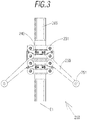
- FIG. 3 shows a schematic plan view of the bearing assembly of FIG. 1 ;
- FIG. 4 shows a schematic elevational view of a free bearing assembly according to the invention
- FIG. 5 shows a schematic side view of the bearing assembly of FIG. 4 ;
- FIG. 6 shows a schematic plan view of the bearing assembly of FIG. 4 ;
- FIG. 7 shows a schematic side view of bearing assemblies on an arrangement of beams upon which the cams are arranged to follow a straight path
- FIG. 8 shows a schematic plan view of the bearing assemblies and a portion of the arrangement of beams of FIG. 7 ;
- FIG. 9 shows a schematic side view of the bearing assemblies and the arrangement of beams of FIG. 7 upon which the cams are arranged to modify the path;
- FIG. 10 shows a schematic plan view of the bearing assemblies and a portion of the arrangement of beams of FIG. 9 ;
- FIG. 11 shows a schematic perspective view of a rail-changing system according to the invention upon which the cams are arranged to follow a straight path;
- FIG. 12 shows a schematic view from another perspective of a rail-changing system according to the invention in which there is no path change
- FIG. 13 shows a schematic view from another perspective of the rail-changing system of FIG. 12 .
- a rail-changing system is illustrated, designated in a general way by the numerical reference 100 which comprises a bearing assembly designated in a general way by the numerical reference 200 and an arrangement of beams designated in a general way by the numerical reference 300 .
- the bearing assembly 200 is of the type that is linked to a carriage (not shown) of those used in an air transport system on beams.
- the type of carriage will not be further discussed since it can be any of those available in the market.
- two fundamental embodiments of bearing assemblies 200 have been shown, one of a motor type in FIGS. 1-3 and another free, in other words, without motor functions, such as those in FIGS. 4-6 .
- Each bearing assembly 200 preferably comprises a frame 201 linked to a pair of elongated extensions 210 , 220 , such that it defines a configuration similar to a yoke (see FIGS. 1 and 4 ).
- the extensions 210 , 220 are preferably laminar elements capable of sustaining, for example, a pair of main wheels 230 with a common rotational axis E 1 arranged horizontally.
- the main wheels 230 are able to circulate on a beam, such that the rotational axis E 1 becomes essentially perpendicular to the line described by the beam, in the plan view.
- main wheels 230 By having a pair of extensions 210 , 220 , in which there is a pair of main wheels 230 , at least four main wheels 230 are obtained, such that they will preferably share a common rotational axis E 1 , since this will logically facilitate the operation when the direction changes.
- the extension 210 , 220 additionally and preferably comprises four auxiliary wheels 231 for each main wheel 230 , the auxiliary wheels 231 arranged in a way that their rotational axis E 2 is essentially perpendicular to the rotational axis E 1 of the main wheel 230 in a front view (see FIG. 1 ) and the auxiliary wheels 231 being able to circulate on a beam, particularly a beam web.
- the auxiliary wheels 231 have a rotational axis E 1 arranged horizontally. Although in the present embodiment there are four auxiliary wheels 231 for each main wheel 230 , a person skilled in the art can modify the number taking into account the needs.
- the main wheel 230 arranged between two pairs of auxiliary wheels 231 in the direction D in which the bearing assembly 200 moves.
- the auxiliary wheels 231 are linked to the extensions 210 , 220 through a pair of plates 232 arranged perpendicularly and on both sides of the pair of main wheels 230 in a direction in which the bearing assembly 200 moves.
- the bearing assembly 200 preferably comprises a pair of cams 250 arranged on both sides of the frame 201 in a direction D in which the bearing assembly 200 moves.
- Each cam 250 is arranged on a rotating basis between the extensions 210 , 220 , in such a way that the rotational axis E 3 of the cam 250 is arranged vertically.
- Each cam 250 is articulated in an elastic way with respect to the frame 201 , for example, with a spring or similar, such that it dampens the irregularities that the route may have.
- the cam 250 also comprises stop means on its free end 252 .
- the stop means preferably comprise a rolling element 251 , the rotational axis E 4 of which is vertical. This rolling element 251 will be responsible for making some beam or similar of the chosen path come in contact with some control means (not shown).
- the bearing assembly 200 comprises first means of actuation preferably linked to each pair of main wheels 230 .
- the first means of actuation comprise a drive unit 205 linked to each pair of main wheels 230 by means of a first belt 260 or similar, for example, a chain. Thanks to the configuration of the first invention, despite the fact that the extensions 210 , 220 should house that first belt 260 and that the thickness may increase, the invention will continue to offer the same stable, reliable and predictable path change. If the mentioned documents of the state of the art include a first belt 260 or similar, the increase in the thickness of its extensions would significantly hinder the change in direction.
- a pair of bearing assemblies 200 one motor and the other free, have been chosen, although it is necessary that they both be for motors.
- the carriage can have as many bearing assemblies 200 as necessary.
- the bearing assembly 200 preferably comprises second means of actuation 254 linked to a cam 250 through a second belt 261 or chain. These second means of actuation 254 operate when the control means so order it.
- the bearing assembly 200 further comprises guiding means linked in a flexible way to each extension 210 , 220 .
- the guiding means have a pair of wedge elements 240 of a trapezoidal profile and made of a material with elastic properties, in which both wedge elements 240 are located above and below the rotational axis E 1 of the main wheels 230 .
- the trapezoidal profile allows the guiding means to carry out their function in both travel directions, with the “sharpened points” turned towards the direction of travel.
- beams 300 for changing the direction of a carriage (not shown) with a bearing assembly 200 as previously described.
- the beams are rails of the passive type, and advantageously, they do not have to be beams with a standard profile or with very specific characteristics, and with the resulting cost increase.
- the configuration of the present arrangement of beams 300 means the beams do not have to have relatively strict tolerances, as occurs in the state of the art.
- the present preferred embodiment of the arrangement of beams 300 comprises a primary central segment 310 and a pair of secondary central segments 320 , 330 , in which one of the secondary central segments 330 has deviation of direction with respect to the primary central segment 310 in plan view (see FIGS. 8 and 10 ), in other words, moving in direction D.
- primary central segment and “secondary central segments”, it should not be understood that the bearing assembly 200 will always change from the first to the second segment, since reversing the direction in which the carriage travels is not ruled out and logically, the order of the segments will also be reversed.
- the primary 310 and secondary 320 , 330 central segments have a transverse cross section that comprises at least one web 312 , 322 , 332 and a flange 311 , 321 , 331 , such that an inverted “T” is defined. It is obvious that if necessary, a person skilled in the art could use a standard profile in which the flanges 311 , 321 , 331 are linked together by a web 312 , 322 , 332 .
- the arrangement of beams 300 preferably comprises a pair of side segments 340 , 350 that runs at a distance from the primary central segment 310 and each one of the secondary central segments 320 , 330 , all in plan view (see FIGS. 8 and 10 ).
- Each side segment 340 , 350 has a transverse cross section in an “L” that comprises a flange 341 , 351 and a web 342 , 352 , such that the flanges 311 , 321 , 331 , 341 , 351 of the central segments 310 , 320 , 330 and the side segments 340 , 350 can receive the main wheels 230 of the same extension 210 , 220 .
- the flanges 311 , 321 , 331 of the central segments 310 , 320 , 330 and the flanges 341 , 351 of the side segments 340 , 350 are turned to face each other.
- the webs 312 , 322 , 332 , 342 , 352 of the central segments 310 , 320 , 330 and the side segments 340 , 350 can receive the auxiliary wheels 231 of the same extension 210 , 220 .
- the webs 312 , 322 , 332 of the central segments 310 , 320 , 330 and the webs 342 , 352 of the side segments 340 , 350 are turned to be essentially parallel to each other.
- Each central segment 310 , 320 , 330 comprises ends 313 , 323 , 333 lacking a web so that the main wheels 230 can change direction without encountering vertical obstacles. Said ends 313 , 323 , 333 face each other, such that the ends 323 , 333 of the secondary central segments reciprocally face the end 313 of the primary central segment 310 .
- the ends 313 , 323 , 333 face each other such that a gap 360 is defined respectively between the separated central segments 310 , 320 , 330 .
- the webs 352 of the side segments 340 , 350 can come in contact with the stop means and the auxiliary wheels 231 on both sides of the web 352 when in use, as can be seen in FIGS. 8, 10 and 11 .
- the side segments 340 , 350 can have a protrusion 344 , 354 wherein they come in contact with the rolling elements 251 .
- These protrusions 344 , 345 can be designed to more precisely define the path of the carriage when the direction changes.
- the side segments 340 , 350 comprise an inclined portion 343 , 353 of a web 342 , 352 and turned towards the central segments 310 , 320 , 330 .
- These inclined portions 343 , 352 direct the relative “contact point” between the rolling elements 251 and the side segments 340 , 350 .
- the carriage When in use, as shown in FIGS. 7-11 , the carriage, hanging from the arrangement of beams 300 by means of the bearing assembly 200 , circulates through the frame 201 . Under these conditions, only the main wheels 230 and the auxiliary wheels 231 closest to the web 312 and to the flanges 311 of the primary central segment 310 are those that support the load of the carriage.
- some control means can order the second drive means to make the cams 250 turn according to the desired path.
- the cams 250 which move in an angular and symmetrical way with respect to the extensions 210 , 220 , reach a position such that the rolling elements 251 properly turn in order to come in contact with the side segments 340 or 350 of the chosen path.
- the rolling elements 251 have already come in contact with the side segments 340 , 350 , and of the four main wheels 230 and sixteen auxiliary wheels 231 , the two main wheels 230 and the eight auxiliary wheels 231 closest to said primary central segment 310 respectively roll on their flanges 311 and their web 312 , and the two main wheels 230 and the eight auxiliary wheels 231 closest to said side segments 340 , 350 respectively roll on their flanges 341 , 351 and their web 342 , 352 .
- the rolling assembly 200 reaches the free end 313 of the web and afterwards, it reaches one of the ends 323 or 333 , depending on the chosen path.
- these ends 313 , 323 and 333 are symmetrical on the upper and lower part of the beam.
- the operation of said drive units 205 can be modified and in this way, a differential effect can be achieved in order to modify the rotational velocity between the different pairs of main wheels 230 linked respectively to each extension 210 , 220 .
- this differential effect the fact that the present rolling assembly 200 rotates around itself with respect to the geometric axis Z, and is not “dragged” by directional elements such as the state of the art can be reinforced.
- the wedge elements 240 of the trapezoidal profile also ensure guiding of the rolling assembly 200 with respect to the web 322 or 332 of the path chosen.
- this jump between central segments 310 to 320 or 310 to 330 there will always be two main wheels 230 of the assembly of four which supports and circulates on the beams, ensuring that the load carried by the carriage does not become unbalanced and none of the main wheels 230 lock in the gap 360 . Conditioning the line to relatively precise tolerances between segments is avoided, thus facilitating construction as well as its maintenance.
Landscapes
- Engineering & Computer Science (AREA)
- Mechanical Engineering (AREA)
- Transportation (AREA)
- Architecture (AREA)
- Civil Engineering (AREA)
- Structural Engineering (AREA)
- General Engineering & Computer Science (AREA)
- Bearings For Parts Moving Linearly (AREA)
- Rolls And Other Rotary Bodies (AREA)
Applications Claiming Priority (3)
| Application Number | Priority Date | Filing Date | Title |
|---|---|---|---|
| ESP201630199 | 2016-02-22 | ||
| ES201630199 | 2016-02-22 | ||
| ES201630199A ES2575123B2 (es) | 2016-02-22 | 2016-02-22 | Conjunto de rodamiento, disposición de vigas para cambio de dirección de un carro con el conjunto de rodamiento y sistema de cambio de raíl con dichos conjunto de rodamiento y disposición de vigas |
Publications (2)
| Publication Number | Publication Date |
|---|---|
| US20170241081A1 US20170241081A1 (en) | 2017-08-24 |
| US10570571B2 true US10570571B2 (en) | 2020-02-25 |
Family
ID=56132497
Family Applications (1)
| Application Number | Title | Priority Date | Filing Date |
|---|---|---|---|
| US15/436,878 Active 2038-02-23 US10570571B2 (en) | 2016-02-22 | 2017-02-20 | Bearing assembly, arrangement of beams for changing direction of a carriage with the bearing assembly and rail-changing system with said bearing assembly and arrangement of beams |
Country Status (4)
| Country | Link |
|---|---|
| US (1) | US10570571B2 (fr) |
| EP (1) | EP3208168B1 (fr) |
| CN (1) | CN107100929B (fr) |
| ES (2) | ES2575123B2 (fr) |
Families Citing this family (5)
| Publication number | Priority date | Publication date | Assignee | Title |
|---|---|---|---|---|
| CN109532857A (zh) * | 2017-09-22 | 2019-03-29 | 中车唐山机车车辆有限公司 | 一种微轨道岔结构及微轨轨道系统 |
| CN109026991B (zh) * | 2018-09-06 | 2020-05-05 | 上海超客机器人有限公司 | 一种上下引导式直角转向系统 |
| JP7103265B2 (ja) * | 2019-02-21 | 2022-07-20 | 株式会社ダイフク | 天井搬送車 |
| DE102019215937A1 (de) * | 2019-10-16 | 2021-04-22 | Robert Bosch Gmbh | Fahrwerk für eine Gondel eines Gondelbahnsystems, Tragmittel für Gondeln eines Gondelbahnsystems, Gondel für ein Gondelbahnsystem, Gondelbahnsystem und Verfahren zum Ansteuern eines Fahrwerks |
| CN111561518B (zh) * | 2020-06-17 | 2021-12-07 | 苏州华正工业科技有限公司 | 一种可承受重载的线性滚针导轨 |
Citations (2)
| Publication number | Priority date | Publication date | Assignee | Title |
|---|---|---|---|---|
| US4354434A (en) * | 1978-04-03 | 1982-10-19 | Jervis B. Webb Company | Track and switch construction for self-propelled vehicles |
| US5419260A (en) * | 1993-12-15 | 1995-05-30 | Hamilton; James | Self-propelled overhead track-mounted moving system |
Family Cites Families (15)
| Publication number | Priority date | Publication date | Assignee | Title |
|---|---|---|---|---|
| FR472199A (fr) * | 1914-05-14 | 1914-11-25 | Hector Baudechon | Aiguillage perfectionné pour transports par monorail |
| US3628462A (en) * | 1969-07-16 | 1971-12-21 | Republic National Bank Of Dall | Vehicle switching apparatus |
| CH588962A5 (en) * | 1975-09-11 | 1977-06-30 | Inventio Ag | Switching point steering arrangement for suspended railway - has moving guides acting together with vehicle guide roller |
| JP4240758B2 (ja) * | 2000-05-22 | 2009-03-18 | 株式会社ダイフク | 搬送設備 |
| DE10248236A1 (de) * | 2002-10-16 | 2004-04-29 | Ina-Schaeffler Kg | Linearführungseinheit |
| DE102007019525A1 (de) * | 2007-04-23 | 2008-10-30 | Thyssenkrupp Transrapid Gmbh | Spurwechseleinrichtung für Magnetschwebebahnen und Bausatz zu deren Herstellung |
| US8807043B2 (en) * | 2009-06-02 | 2014-08-19 | Beamways Ab | Track and bogie for suspended vehicles |
| CN102447365A (zh) * | 2010-10-14 | 2012-05-09 | 刘忠臣 | 外螺线转子永磁电机及永磁悬浮轮轨车路系统 |
| DE102010060744A1 (de) * | 2010-11-23 | 2012-05-24 | Vossloh-Werke Gmbh | Kombination aus einer Führungsplatte und einem Keilelement sowie System zum Befestigen einer Schiene für ein Schienenfahrzeug auf einem Untergrund |
| ES2362847B1 (es) * | 2011-03-22 | 2012-04-03 | Luis Carrillo Lostao | Dispositivo automatizado para cambio de ra�?l. |
| TW201242701A (en) * | 2011-04-22 | 2012-11-01 | Hon Hai Prec Ind Co Ltd | Guideway mechanism |
| CN103806351B (zh) * | 2012-11-08 | 2015-09-09 | 于君 | 一种轨道及其专用车辆 |
| CN202971572U (zh) * | 2012-12-10 | 2013-06-05 | 吴旻杰 | 具有保持装置的线性滑座 |
| KR101419359B1 (ko) * | 2013-04-08 | 2014-07-16 | 주식회사 에스에프에이 | 반송대차 및 이를 이용하는 반송시스템 |
| CN204605787U (zh) * | 2015-04-28 | 2015-09-02 | 北京中索国游索道工程技术有限公司 | 脱挂抱索器 |
-
2016
- 2016-02-22 ES ES201630199A patent/ES2575123B2/es not_active Expired - Fee Related
-
2017
- 2017-02-10 ES ES17382066T patent/ES2748890T3/es active Active
- 2017-02-10 EP EP17382066.3A patent/EP3208168B1/fr active Active
- 2017-02-20 US US15/436,878 patent/US10570571B2/en active Active
- 2017-02-22 CN CN201710097031.7A patent/CN107100929B/zh active Active
Patent Citations (2)
| Publication number | Priority date | Publication date | Assignee | Title |
|---|---|---|---|---|
| US4354434A (en) * | 1978-04-03 | 1982-10-19 | Jervis B. Webb Company | Track and switch construction for self-propelled vehicles |
| US5419260A (en) * | 1993-12-15 | 1995-05-30 | Hamilton; James | Self-propelled overhead track-mounted moving system |
Also Published As
| Publication number | Publication date |
|---|---|
| CN107100929B (zh) | 2020-06-23 |
| EP3208168B1 (fr) | 2019-07-03 |
| ES2575123B2 (es) | 2016-11-04 |
| CN107100929A (zh) | 2017-08-29 |
| EP3208168A1 (fr) | 2017-08-23 |
| US20170241081A1 (en) | 2017-08-24 |
| ES2575123A1 (es) | 2016-06-24 |
| ES2748890T3 (es) | 2020-03-18 |
Similar Documents
| Publication | Publication Date | Title |
|---|---|---|
| US10570571B2 (en) | Bearing assembly, arrangement of beams for changing direction of a carriage with the bearing assembly and rail-changing system with said bearing assembly and arrangement of beams | |
| US9212454B2 (en) | Branching device and center guide-type track-based transportation system | |
| US8985310B2 (en) | Sorting conveyor | |
| EP2979998B1 (fr) | Équipement pour transport de marchandises | |
| US9895977B2 (en) | Article transport facility | |
| EP1375287B1 (fr) | Voie de guidage et vehicule pour un système de transport | |
| US9481529B2 (en) | Tilt-tray conveying carriage and tilt-tray sorting installation | |
| US10858788B2 (en) | Monorail switch using a gravity-assisted actuating mechanism | |
| JP6848373B2 (ja) | 物品搬送設備 | |
| CN101190747B (zh) | 台车合流装置 | |
| US20200131001A1 (en) | Supporting device for a rotary platform in an elevator system | |
| EP0960848B1 (fr) | Pont roulant | |
| KR101292210B1 (ko) | 이송용 대차 및 가이드레일 | |
| US10399622B2 (en) | Conveying apparatus for conveying transporting structures | |
| US8082854B2 (en) | Chassis for a cable or pipeline trolley | |
| US3829175A (en) | Rail-suspended carriage | |
| CN106429716A (zh) | 导轨装置及用于安装导轨的方法 | |
| CN108367763B (zh) | 铁道车辆用导向转向架 | |
| KR20200129145A (ko) | 운송 시스템 | |
| US8714092B2 (en) | Pivot switch system and method | |
| KR20170006347A (ko) | 2축 휠 어셈블리 및 이를 구비한 레일유도방식 운반차 | |
| WO2016012929A1 (fr) | Unité de rouleau pour système de transport par câble | |
| RU2623360C2 (ru) | Роликовое устройство для перевода крестовины | |
| US20220032783A1 (en) | Stabilisation and levitation mechanism for a dedicated vehicle, taking into account the interoperability with existing transport systems in the vicinity of switches and routes of conventional vehicles and how the vehicle is stabilised in the stabilisation and levitation mechanism | |
| CN109693997A (zh) | 用于人员输送机的链驱动器 |
Legal Events
| Date | Code | Title | Description |
|---|---|---|---|
| STPP | Information on status: patent application and granting procedure in general |
Free format text: DOCKETED NEW CASE - READY FOR EXAMINATION |
|
| STPP | Information on status: patent application and granting procedure in general |
Free format text: NON FINAL ACTION MAILED |
|
| STPP | Information on status: patent application and granting procedure in general |
Free format text: RESPONSE TO NON-FINAL OFFICE ACTION ENTERED AND FORWARDED TO EXAMINER |
|
| STPP | Information on status: patent application and granting procedure in general |
Free format text: NOTICE OF ALLOWANCE MAILED -- APPLICATION RECEIVED IN OFFICE OF PUBLICATIONS |
|
| STPP | Information on status: patent application and granting procedure in general |
Free format text: PUBLICATIONS -- ISSUE FEE PAYMENT VERIFIED |
|
| STCF | Information on status: patent grant |
Free format text: PATENTED CASE |
|
| CC | Certificate of correction | ||
| MAFP | Maintenance fee payment |
Free format text: PAYMENT OF MAINTENANCE FEE, 4TH YR, SMALL ENTITY (ORIGINAL EVENT CODE: M2551); ENTITY STATUS OF PATENT OWNER: SMALL ENTITY Year of fee payment: 4 |