US10569883B2 - Deployable table - Google Patents
Deployable table Download PDFInfo
- Publication number
- US10569883B2 US10569883B2 US15/429,880 US201715429880A US10569883B2 US 10569883 B2 US10569883 B2 US 10569883B2 US 201715429880 A US201715429880 A US 201715429880A US 10569883 B2 US10569883 B2 US 10569883B2
- Authority
- US
- United States
- Prior art keywords
- table assembly
- latch
- console
- seating arrangement
- locking device
- Prior art date
- Legal status (The legal status is an assumption and is not a legal conclusion. Google has not performed a legal analysis and makes no representation as to the accuracy of the status listed.)
- Active, expires
Links
- 230000007246 mechanism Effects 0.000 claims description 18
- 230000004044 response Effects 0.000 claims description 4
- 230000007704 transition Effects 0.000 description 3
- 230000004913 activation Effects 0.000 description 2
- 230000008878 coupling Effects 0.000 description 2
- 238000010168 coupling process Methods 0.000 description 2
- 238000005859 coupling reaction Methods 0.000 description 2
- 238000006073 displacement reaction Methods 0.000 description 2
- 230000000712 assembly Effects 0.000 description 1
- 238000000429 assembly Methods 0.000 description 1
- 239000002131 composite material Substances 0.000 description 1
- 239000000463 material Substances 0.000 description 1
- 239000002184 metal Substances 0.000 description 1
- 230000002093 peripheral effect Effects 0.000 description 1
Images


Classifications
-
- A—HUMAN NECESSITIES
- A47—FURNITURE; DOMESTIC ARTICLES OR APPLIANCES; COFFEE MILLS; SPICE MILLS; SUCTION CLEANERS IN GENERAL
- A47C—CHAIRS; SOFAS; BEDS
- A47C7/00—Parts, details, or accessories of chairs or stools
- A47C7/62—Accessories for chairs
- A47C7/68—Arm-rest tables ; or back-rest tables
- A47C7/70—Arm-rest tables ; or back-rest tables of foldable type
-
- B—PERFORMING OPERATIONS; TRANSPORTING
- B60—VEHICLES IN GENERAL
- B60N—SEATS SPECIALLY ADAPTED FOR VEHICLES; VEHICLE PASSENGER ACCOMMODATION NOT OTHERWISE PROVIDED FOR
- B60N3/00—Arrangements or adaptations of other passenger fittings, not otherwise provided for
- B60N3/001—Arrangements or adaptations of other passenger fittings, not otherwise provided for of tables or trays
- B60N3/002—Arrangements or adaptations of other passenger fittings, not otherwise provided for of tables or trays of trays
-
- B—PERFORMING OPERATIONS; TRANSPORTING
- B64—AIRCRAFT; AVIATION; COSMONAUTICS
- B64D—EQUIPMENT FOR FITTING IN OR TO AIRCRAFT; FLIGHT SUITS; PARACHUTES; ARRANGEMENT OR MOUNTING OF POWER PLANTS OR PROPULSION TRANSMISSIONS IN AIRCRAFT
- B64D11/00—Passenger or crew accommodation; Flight-deck installations not otherwise provided for
- B64D11/06—Arrangements of seats, or adaptations or details specially adapted for aircraft seats
- B64D11/0602—Seat modules, i.e. seat systems including furniture separate from the seat itself
- B64D11/0605—Seat modules, i.e. seat systems including furniture separate from the seat itself including tables or desks
-
- B—PERFORMING OPERATIONS; TRANSPORTING
- B64—AIRCRAFT; AVIATION; COSMONAUTICS
- B64D—EQUIPMENT FOR FITTING IN OR TO AIRCRAFT; FLIGHT SUITS; PARACHUTES; ARRANGEMENT OR MOUNTING OF POWER PLANTS OR PROPULSION TRANSMISSIONS IN AIRCRAFT
- B64D11/00—Passenger or crew accommodation; Flight-deck installations not otherwise provided for
- B64D11/06—Arrangements of seats, or adaptations or details specially adapted for aircraft seats
- B64D11/0638—Arrangements of seats, or adaptations or details specially adapted for aircraft seats with foldable tables, trays or cup holders
Definitions
- This invention relates to a table and in particular to a deployable table for use in a seating arrangement.
- the table typically employed in economy class in aircraft typically comprises fold-down tables which are coupled to the back wall of a seating arrangement, which when not in use are held in a substantially flush position via a cam mechanism.
- fold-down tables which are coupled to the back wall of a seating arrangement, which when not in use are held in a substantially flush position via a cam mechanism.
- business class there is a wider variety of tables available ranging from those which slide out from a central console on an arcuate rail mechanism, to those which fold out to provide a table with a plurality of leaves.
- the invention provides a seating arrangement comprising at least one seat; a console adjacent the at least one seat; a deployable table assembly; and locking device, wherein the table assembly is movable in a longitudinal direction from a stowed position into a deployed position in which it is located on an upper surface of said console, and wherein the locking device is operable to releasably engage the table assembly in the deployed position to prevent movement of the table assembly in a lateral direction.
- the console includes a recess for receiving the table assembly in the stowed position, said table assembly being movable into and out of said recess in the longitudinal direction.
- the table assembly includes a table, the table being disposed in a vertical orientation when in the stowed position.
- the console comprises base and upper portions, the table assembly being located in the upper portion in the stowed position.
- the table assembly comprises a table and a carriage for the table.
- the locking device is operable to releasably engage the carriage.
- the table is pivotably coupled to the carriage for pivoting movement about an axis that extends in the longitudinal direction.
- the table is pivotable about the axis between a vertical orientation and a horizontal orientation, the table adopting the horizontal orientation in the deployed position.
- the table is pivotably coupled to the carriage by at least one hinge.
- the carriage includes a device for facilitating movement of the carriage such as one or more wheels, rollers, rails and/or slides.
- the seating arrangement further includes an actuation device operable to move the table assembly from the stowed position towards the deployed position, the actuation device optionally comprising resilient biasing element arranged to urge the table assembly towards the deployed position.
- the actuation device is operable by a controller to actuate the table from the stowed position into a primary intermediate position.
- the actuation device comprises at least one spring coupled to a ram.
- the controller comprises a switch which is in mechanical or electrical communication with the actuation device.
- the locking device comprises a latch that is releasably engageable with a corresponding latch-receiving recess provided in the table assembly.
- the latch is movable between a retracted state in which it is located within the console and an extended state in which it projects upwardly from the upper surface of the console.
- the latch and the latch-receiving recess are aligned with one another when the table assembly is in the deployed position.
- the latch and latch-receiving recess are shaped and dimensioned to prevent lateral movement of the table assembly relative to the console when mutually engaged.
- the locking device is co-operable with the table assembly such that movement of the table assembly from the stowed position into a secondary intermediate position causes the latch to move from its retracted state to its extended state.
- the locking device is co-operable with the table assembly such that movement of the table assembly from a secondary intermediate state towards the stowed position causes the latch to move from its extended state to its retracted state.
- the locking device includes a linkage mechanism that couples the table assembly to the latch in order to actuate the latch from the retracted state to the extended state in response to movement of the table assembly into the second intermediate position.
- the linkage mechanism includes a linkage that is pivotably coupled to the console and to the latch in order to translate movement of the table assembly in the longitudinal direction into upwards movement of the latch.
- the latch is movable from its engaged state to its retracted state by engagement with a surface of the latch-receiving recess as the table assembly moves from the secondary intermediate state to the stowed position.
- At least one support member is provided on the in-use underside of the table, the at least one support member being engageable with the upper surface of the console when the table is in the deployed position.
- the at least one support member is deployable between a use position in which it projects from the underside of the table and a stowed position in which it is located in or against the table.
- the at least one support member is resiliently biased to adopt its deployed state.
- the table assembly incorporates an abutment device operable to prevent movement of the table assembly in a longitudinal direction in-use.
- the abutment device comprises at least one spring coupled to a lever, wherein the lever is pivotably coupled to a pin which is operable to releasably engage a cavity in-use.
- FIG. 1 is a side sectional view showing part of a seating arrangement and showing a deployable table in a stowed position, the table embodying one aspect of the present invention
- FIG. 2 is an enlarged side sectional view of a locking device of the deployable table of FIG. 1 ;
- FIG. 3 is a plan view of the deployable table of FIG. 1 in the stowed position
- FIG. 4 is an enlarged plan view of the deployable table of FIG. 1 in the stowed position
- FIG. 5 is a side sectional view of the deployable table of FIG. 1 in a secondary intermediate position
- FIG. 6 is an enlarged side sectional view of the deployable table of FIG. 1 in the secondary intermediate position showing the engagement of the locking device;
- FIG. 7 is a plan view of the deployable table of FIG. 1 in the secondary intermediate position
- FIG. 8 is a sectional view of the seating arrangement of the deployable table of FIG. 1 in the deployed position
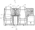
- FIG. 9 is a front perspective view of the seating arrangement showing the deployable table of FIG. 1 in a deployed position
- FIG. 10 is an enlarged front perspective view of the seating arrangement showing the deployable table of FIG. 1 in a deployed position;
- FIG. 11 is a sectional side view of the seating arrangement showing the deployable table of FIG. 1 in the intermediate position;
- FIG. 12 is a sectional side view of the seating arrangement showing the deployable table of FIG. 1 in the deployed position.
- FIGS. 1 to 4 show a seating arrangement 100 , in particular an aircraft seating arrangement, embodying one exemplary aspect of the invention, the seating arrangement incorporating a deployable table assembly 101 embodying another exemplary aspect of the invention.
- the deployable table assembly 101 incorporates a table 102 and a table deployment mechanism 104 , which is configured to transition the table 102 between stowed and deployed positions (as shown in FIGS. 1 and 9 respectively). This transition typically incorporates one or more intermediate positions (shown in FIG. 5 ) in-use.
- the seating arrangement 100 comprises at least one seat 103 and a console 105 located adjacent the seat 103 .
- the seating arrangement 101 comprises two (or more) seats 103 that are side-by-side, the, or a respective, console 105 is located between adjacent seats 103 .
- the table 102 may comprise a single leaf table; however it may alternatively comprise multiple leaves.
- the deployable table comprising the table 102 and table deployment mechanism 104 is provided within the console 105 .
- the console 105 is shaped and dimensioned to define a recess 106 therein, within which the table 102 and at least part of the table deployment mechanism 104 may be disposed when in the stowed position.
- the console 105 may incorporate one or more additional deployable table assemblies 101 such that where, for example, the seating arrangement 100 incorporates first and second seats 103 with a console 105 located therebetween (as shown in FIG. 8 ), each occupant may be provided with their own deployable table assembly 101 , with both typically being provided within the same console 105 (see FIG. 8 ).
- the recess 106 typically includes an aperture 114 through which the table 102 passes when transitioning between stowed and deployed positions.
- the console 105 typically comprises a base portion 109 and an upper portion 107 with the table 102 typically being stowed in the upper portion 107 , the table deployment mechanism 104 typically being provided, at least in part, in both the upper and base portions 107 , 109 .
- the upper portion 107 is coupled to or mounted on the base portion 109 .
- the upper portion 107 is typically larger in dimension than the base portion 107 , such that the upper portion 107 occupies only part of the surface area of an upper face 110 of the base portion 109 , upon which the upper portion 107 is provided.
- the surface area of the upper face 110 of the base portion 109 which is not occupied by the upper portion 107 may provide an armrest or support surface for one or more objects for an occupant of the seat 103 .
- the table 102 is stowed within the console 105 such that in the stowed position the table 102 is disposed substantially perpendicular to the ground surface on which the seating arrangement 100 rests during use.
- This orientation which may be referred to as a vertical orientation, is substantially perpendicular to the orientation of the table when in the deployed position (which may be referred to as a horizontal orientation).
- the table 102 may be coupled to the table deployment mechanism 104 by any suitable coupling device.
- the table deployment mechanism 104 typically comprises a carriage 112 , abutment device 111 , actuation device 130 , and is advantageously co-operable with locking device 113 as is described in more detail hereinafter.
- the carriage 112 is movable back and forth into and out of the recess 106 via the aperture 114 in a longitudinal direction that, in preferred embodiments, is substantially parallel with the direction in which a seated passenger faces.
- the table 102 is mounted on the carriage 112 and so is movable into and out of the recess 106 via the aperture 114 in the longitudinal direction. In preferred embodiments, the table 102 is in its vertical orientation during such movement.
- the carriage 112 typically includes a device for facilitating movement of the carriage such as one or more wheel(s), roller(s), rails(s) and/or slides(s). In the illustrated embodiment wheel 108 is provided for this purpose.
- the table 102 is coupled to the carriage 112 via at least one pivot device 115 such as a hinge.
- the table 102 is pivotable about the hinge such that when in the deployed position the table is disposed substantially parallel to the ground surface on which the seating arrangement 100 rests during use (as shown in FIG. 8 ), i.e, the table is in the horizontal orientation.
- the actuation device 130 is operable to actuate the table 102 towards a primary intermediate position in-use (not shown).
- the actuation device 130 typically comprises at least one resilient biasing member arranged to urge the table out of the recess 106 into the primary intermediate position.
- the actuation device 130 typically comprises a spring coupled to a ram.
- the actuation device 130 is typically in a primed state.
- the actuation device 130 comprises a resilient biasing element such as a spring, this may be in a compressed state and arranged to urge the table towards the primary intermediate position.
- the actuation device 130 is positioned such as to abut the carriage 112 .
- the actuation device 130 is typically coupled to a controller (not shown), typically comprising a user-operable latch, which upon activation is configured to release the actuation device 130 from its primed state, whereby the actuation device 130 urges the table 102 into the primary intermediate position.
- a controller typically comprising a user-operable latch, which upon activation is configured to release the actuation device 130 from its primed state, whereby the actuation device 130 urges the table 102 into the primary intermediate position.
- a user-operable latch may be coupled to the table 102 or carriage 112 to selectively prevent movement of the table under the bias of the actuation device 130 until the latch is released.
- In the primary intermediate position at least part of the table 102 extends out of the aperture 114 of the console 105 .
- the table 102 is in the primary intermediate position it is movable into a secondary intermediate position (shown in FIGS.
- the table deployment mechanism 104 may incorporate an additional actuation device (not shown), such as a motor, which is configured to displace the table into the secondary intermediate position upon activation of the actuation device 130 .
- the controller (not shown) is typically provided upon the central console 105 , such as upon the base portion 109 .
- the controller is typically in mechanical or electrical communication with the actuation device 130 .
- the actuation device 130 may be provided on a rear wall of the recess 106 .
- the abutment device 111 may be provided on a rear portion 118 of the carriage 112 , the rear portion 118 typically extending substantially perpendicular to the body of the carriage 112 in an upward direction.
- the abutment device 111 comprises a spring 117 coupled to a lever 119 .
- the lever 119 and the rear portion 118 provide an elongate supporting edge.
- the abutment device 111 is typically in a primed state.
- the abutment device 111 comprises a resilient biasing element such as a spring, this may be in a compressed state.
- the abutment device 111 is positioned such as to abut the table 102 .
- the rear portion 118 of the carriage 112 is adapted to substantially occupy the dimensions of the aperture 114 of the console 105 .
- the lever 119 is adapted to extend out of, at least in part, the aperture 114 in-use.
- the abutment device 111 is typically pivotably coupled to a pin 133 , which is extendable into a cavity 134 .
- the pin 133 typically extends substantially through the carriage 112 , in a downward direction.
- the cavity 134 is shaped and dimensioned to receive the pin 133 such that the pin 133 is operable to releasably engage the cavity 134 when the deployable table 101 is in the deployed position.
- the table 102 is pivotable about a horizontal axis extending in the longitudinal direction when in the secondary intermediate position (as shown in FIG. 5 ), where the horizontal axis is to be understood to comprise the axis extending longitudinally substantially parallel with the ground surface upon which the seating arrangement 101 rests during use.
- the table 102 is configured to pivot through approximately 90° from its secondary intermediate position to its deployed position such that the table 102 , when pivoted into the deployed position is substantially horizontally disposed and extends across the respective seat 103 (i.e. in front of a seated passenger in use).
- the table 102 is optionally configured to pivot only in one direction from the secondary intermediate position and, to this end, the pivot device 115 , which typically comprises a hinge, may include a stop for preventing the table 102 from pivoting in the opposite direction relative to the seat 103 .
- the pivot device 115 for each table 102 provided within the console 105 are configured to pivot in opposing directions when transitioning from the secondary intermediate position to the deployment position (as shown in FIG. 8 ).
- the lever 119 of the abutment device 111 is configured to pivot out of the aperture 114 in a substantially longitudinal direction in-use into an extended position (as shown in FIG. 8 ).
- the pin 133 is configured to extend in a substantially lateral direction to releasably engage the cavity 134 .
- this engagement is operable to lock the abutment device 111 in the extended position in-use.
- the abutment device 111 is configured to prevent movement of the table 102 in the longitudinal direction in-use.
- the abutment device 111 is further configured such that when the table 102 is pivoted back into the secondary intermediate position, the in-use topside of the table 102 is operable to abut the lever 119 of the abutment device 111 .
- the lever 119 is operable to retract into the recess 10 upon contact with the table 102 , to this end the lever 119 is chamfered such as to provide a substantially round peripheral edge,
- Locking device 113 which is shown to include an extendable latch 126 , is configured to releasably engage the carriage 112 when the table 102 is in the deployed position.
- the latch 126 is provided on the base portion 109 of the console 105 in the region in front of the upper portion 107 .
- the latch 126 is movable between a retracted state (see for example FIG. 2 ) in which it is located within the console 105 (optionally, such that its upper surface is substantially flush with the upper surface 110 of the console 105 ) and an extended state (see for example FIG. 6 ) in which it projects upwardly from the upper surface 110 of the console 105 ), typically through an aperture 127 formed in the surface 110 .
- the carriage 112 includes a corresponding latch-receiving recess 122 in its underside, in which the latch 126 is located in its extended state, i.e. when the locking device is engaged.
- the arrangement is such that the latch 126 and the recess 122 are aligned with one another when the table 102 is in its secondary intermediate position (and also the deployed position).
- the locking device 113 is provided on the console 105 and, when the latch 126 is engaged with the carriage, prevents relative movement between the carriage 112 and the console 105 in a lateral direction at least, the lateral direction being perpendicular to the longitudinal direction, i.e. a direction that is transverse with respect to the seat 103 .
- this engagement prevents lateral movement of the table 102 relative to the console 105 .
- the locking device 113 is coupled to or otherwise co-operable with the carriage 112 such that movement of the carriage 112 into the secondary intermediate state causes the latch 126 to adopt its extended state.
- the locking device 113 is may also be coupled to or otherwise co-operable with the carriage 112 such that movement of the carriage 112 from the secondary intermediate state towards the stowed position causes the latch 126 to adopt its retracted state.
- the locking device 113 includes a linkage mechanism 123 that couples the carriage 112 to the latch 126 in order to actuate the latch 126 from the retracted state to the extended state in response to movement of the carriage 112 , from the first intermediate position to the second intermediate position.
- the linkage mechanism 123 couples with a part 129 of the carriage 112 that is located below the surface 110 .
- the coupling may be fixed (e.g. by way of a cable (not shown)) or may involve engagement of the part 129 and the linkage mechanism 123 as the carriage 112 moves towards the secondary intermediate position.
- the linkage mechanism 123 includes a linkage 124 that is pivotably coupled to the console 105 and to the latch 126 in order to translate movement of the carriage 112 in the longitudinal direction into upwards movement of the latch 126 .
- the illustrated linkage mechanism 123 includes a linkage member 120 that couples between the linkage 124 to the carriage part 129 in order to pivot the linkage 124 in response to movement of the carriage 112 towards the secondary intermediate position thereby moving the latch 126 to its engaged state.
- the preferred arrangement is such that the latch 126 is actuated into its engaged state at substantially the same time as the carriage 112 reaches the secondary intermediate position.
- the latch 126 is moved to its retracted state by engagement with the carriage 112 as the carriage moves from the secondary intermediate state to the stowed position. This may be achieved by providing the foremost (in the longitudinal direction) surface of the latch 126 and/or the foremost surface of the recess 122 with a shape that causes the latch 126 to be pushed downwards when the recess 122 engages with the latch 126 as the carriage moves from the secondary intermediate state to the stowed position.
- the foremost surface 131 of the recess 122 is oblique with respect to the direction of movement of the carriage such that it pushes the latch 126 downwards when the carriage moves.
- the locking device 113 is conveniently provided within the console 105 , typically within the base portion 109 and is configured to extend therefrom. Typically the locking device 113 , and more particularly the latch 126 , extends from the upper face 110 of the base portion 109 in-use. In the stowed position the latch 126 is retractable within the base portion 109 , such that it is substantially flush with the upper face 110 (as shown in FIGS. 2 to 4 ).
- the linkages 120 , 124 may comprise one or more connecting rods comprising metal and/or plastic and/or a composite material or any other suitable material. The linkages 120 , 124 may incorporate one or more resilient biasing elements, such as a spring, to assist movement of the latch 126 into and/or out of its extended state.
- the linkage 120 may comprise a rod, optionally incorporating a biasing element, which is coupled to the carriage 112 at one end and to one end of the pivotable linkage 124 at the other.
- the other end of the linkage 124 is coupled to the latch 126 , e.g. by a further link 133 , such that the linkage 124 , when pivoted, extends the latch 126 .
- the linkage, or lever, 124 is pivotably coupled to the base portion 109 , such that the displacement of the rod 122 in the longitudinal (or forward) direction causes pivoting movement of the lever 124 .
- one or more support members 116 are provided for supporting the table 102 on the upper surface 110 when in the deployed position.
- the or each support member 116 which may take the form of a leg or other projection, is provided on the in-use underside of the table 102 and may be retractable into or foldable against the underside of the table 112 .
- the support member 116 is deployable between a use position in which it projects from the underside of the table and a stowed position in which it is located in or against said table.
- The, or each, support member 116 is configured such that when the deployable table 101 is in the stowed position, the support member 116 is folded against the table 102 , and may lie substantially flat against the underside (as shown in FIG.
- the, or each, support member 116 is configured such that when the deployable table 101 is in the deployed position the support member 116 extends substantially perpendicular to the table 102 , whereby it is configured to rest upon the base portion 109 , such as upon the upper face 110 thereof (as shown in FIGS. 8 and 9 ).
- The, or each, support member 116 may be resiliently biased to adopt its use position such that the use position is adopted as the table emerges from the recess 106 .
- the table 102 moves to the primary intermediate position (as shown in FIGS. 1 to 4 ).
- the table 102 may then be pulled by the user into the secondary intermediate position (as shown in FIGS. 5 to 7 ).
- the forward movement of the carriage 112 operates the locking device 113 causing the latch 12 to extend from the console 105 into the recess 122 .
- the table 102 is pivotable about the pivot device 115 into the deployed position (as shown in FIG. 8 ) whereupon the abutment device 111 is configured to releasably lock in an extended position.
- the locking device 113 when the table 102 is in its deployed position, provides stability, in particular by preventing or at least restricting lateral movement of the table 102 . Stability is further enhanced by the support member 116 . Tables embodying the invention can therefore be easily deployed and stowed and are stable in use.
Landscapes
- Engineering & Computer Science (AREA)
- Aviation & Aerospace Engineering (AREA)
- Transportation (AREA)
- Mechanical Engineering (AREA)
- Passenger Equipment (AREA)
Applications Claiming Priority (2)
| Application Number | Priority Date | Filing Date | Title |
|---|---|---|---|
| GB1602498.6 | 2016-02-11 | ||
| GB1602498.6A GB2547245B (en) | 2016-02-11 | 2016-02-11 | Deployable table |
Publications (2)
| Publication Number | Publication Date |
|---|---|
| US20170233078A1 US20170233078A1 (en) | 2017-08-17 |
| US10569883B2 true US10569883B2 (en) | 2020-02-25 |
Family
ID=55697582
Family Applications (1)
| Application Number | Title | Priority Date | Filing Date |
|---|---|---|---|
| US15/429,880 Active 2037-11-27 US10569883B2 (en) | 2016-02-11 | 2017-02-10 | Deployable table |
Country Status (3)
| Country | Link |
|---|---|
| US (1) | US10569883B2 (de) |
| EP (1) | EP3205579B1 (de) |
| GB (1) | GB2547245B (de) |
Families Citing this family (2)
| Publication number | Priority date | Publication date | Assignee | Title |
|---|---|---|---|---|
| US10730627B2 (en) * | 2015-04-13 | 2020-08-04 | Safran Seats | Seat module comprising an armrest with an optimised design |
| US10889377B1 (en) * | 2019-06-28 | 2021-01-12 | B/E Aerospace, Inc. | Braking aircraft table system |
Citations (12)
| Publication number | Priority date | Publication date | Assignee | Title |
|---|---|---|---|---|
| US3632161A (en) * | 1970-07-13 | 1972-01-04 | Universal Oil Prod Co | Side arm stowable table |
| US4834449A (en) * | 1988-04-18 | 1989-05-30 | Fred Engelman | Collapsible table assembly |
| US5050929A (en) * | 1989-10-24 | 1991-09-24 | Gueringer John M | Auxiliary furniture tray system |
| DE19705754A1 (de) | 1997-02-14 | 1998-08-20 | Schaltbau Ag | Klapptisch für einen Sitzplatz in einem Fahrzeug |
| EP1172252A1 (de) | 2000-07-15 | 2002-01-16 | Marlene Schneppendahl | Versenkbarer Klapptisch |
| US8336956B2 (en) | 2009-11-23 | 2012-12-25 | Zodiac Seats Us Llc | Table stop assembly |
| WO2013030797A1 (en) | 2011-09-02 | 2013-03-07 | Societe Industrielle Et Commerciale De Materiel Aeronautique | Premium seat comprising a stowable food tray and a sliding armrest |
| US8528968B2 (en) | 2010-11-30 | 2013-09-10 | Be Aerospace, Inc. | Stowable passenger seat tray table |
| US20140300148A1 (en) * | 2013-04-04 | 2014-10-09 | B/E Aerospace, Inc. | Vertically stowed tray table assembly with translational movement |
| US9150129B2 (en) | 2013-04-04 | 2015-10-06 | B/E Aerospace, Inc. | Passenger seat with drop-down armrest assembly |
| US9481464B2 (en) | 2014-04-07 | 2016-11-01 | Zodiac Seats Uk Limited | Table arrangement |
| US9731829B2 (en) | 2014-04-07 | 2017-08-15 | Zodiac Seats Uk Limited | Table arrangement |
Family Cites Families (1)
| Publication number | Priority date | Publication date | Assignee | Title |
|---|---|---|---|---|
| US8205563B2 (en) * | 2009-06-29 | 2012-06-26 | St. Louis Designs, Inc. | Aircraft table system with rolling sled member |
-
2016
- 2016-02-11 GB GB1602498.6A patent/GB2547245B/en active Active
-
2017
- 2017-02-09 EP EP17155507.1A patent/EP3205579B1/de active Active
- 2017-02-10 US US15/429,880 patent/US10569883B2/en active Active
Patent Citations (13)
| Publication number | Priority date | Publication date | Assignee | Title |
|---|---|---|---|---|
| US3632161A (en) * | 1970-07-13 | 1972-01-04 | Universal Oil Prod Co | Side arm stowable table |
| US4834449A (en) * | 1988-04-18 | 1989-05-30 | Fred Engelman | Collapsible table assembly |
| US5050929A (en) * | 1989-10-24 | 1991-09-24 | Gueringer John M | Auxiliary furniture tray system |
| DE19705754A1 (de) | 1997-02-14 | 1998-08-20 | Schaltbau Ag | Klapptisch für einen Sitzplatz in einem Fahrzeug |
| EP1172252A1 (de) | 2000-07-15 | 2002-01-16 | Marlene Schneppendahl | Versenkbarer Klapptisch |
| US8336956B2 (en) | 2009-11-23 | 2012-12-25 | Zodiac Seats Us Llc | Table stop assembly |
| US8528968B2 (en) | 2010-11-30 | 2013-09-10 | Be Aerospace, Inc. | Stowable passenger seat tray table |
| WO2013030797A1 (en) | 2011-09-02 | 2013-03-07 | Societe Industrielle Et Commerciale De Materiel Aeronautique | Premium seat comprising a stowable food tray and a sliding armrest |
| US9216665B2 (en) | 2011-09-02 | 2015-12-22 | Zodiac Seats France | Premium seat offering extra wide bed |
| US20140300148A1 (en) * | 2013-04-04 | 2014-10-09 | B/E Aerospace, Inc. | Vertically stowed tray table assembly with translational movement |
| US9150129B2 (en) | 2013-04-04 | 2015-10-06 | B/E Aerospace, Inc. | Passenger seat with drop-down armrest assembly |
| US9481464B2 (en) | 2014-04-07 | 2016-11-01 | Zodiac Seats Uk Limited | Table arrangement |
| US9731829B2 (en) | 2014-04-07 | 2017-08-15 | Zodiac Seats Uk Limited | Table arrangement |
Non-Patent Citations (2)
| Title |
|---|
| European Search Report for corresponding European Application No. EP17155507, dated Jun. 8, 2017. |
| UK Search Report for corresponding UK Application No. GB1602498.6, dated Jul. 13, 2016. |
Also Published As
| Publication number | Publication date |
|---|---|
| GB2547245B (en) | 2020-01-22 |
| EP3205579B1 (de) | 2020-09-02 |
| US20170233078A1 (en) | 2017-08-17 |
| GB201602498D0 (en) | 2016-03-30 |
| EP3205579A1 (de) | 2017-08-16 |
| GB2547245A (en) | 2017-08-16 |
Similar Documents
| Publication | Publication Date | Title |
|---|---|---|
| JP4434075B2 (ja) | 車両用シートの移動装置 | |
| CN101992702B (zh) | 车辆座椅,特别是机动车辆座椅 | |
| US10279912B2 (en) | Passenger seating with partition assembly | |
| US7100984B2 (en) | Fold-down seat and a vehicle including such a seat | |
| US8632113B2 (en) | Stowable seat arrangement for a motor vehicle | |
| US7850220B2 (en) | Mono leg transformer seat | |
| EP3227183B1 (de) | Tischeinheit | |
| JP6728979B2 (ja) | 車両用シート | |
| CN102555857B (zh) | 用于车辆座椅的折叠下俯式装置 | |
| US8439448B2 (en) | Buckle for center occupant for bench seat with extended travel | |
| US7377571B2 (en) | Collapsible seat mechanism with integrated subfloor | |
| US11091071B2 (en) | Seat provided with a system for locking the tray table in the event of an impact | |
| US10569883B2 (en) | Deployable table | |
| US7108329B1 (en) | Seating unit with retractable footrest | |
| US7455342B2 (en) | Stowable ottoman for a vehicle passenger cabin | |
| JP2013112127A (ja) | 車両用シート | |
| CN102612452B (zh) | 可收缩的撞针以及具有可收缩的撞针的座椅 | |
| CN211765095U (zh) | 用于车辆的座椅总成 | |
| US11958614B2 (en) | Seat, in particular for an aircraft, with a single actuator | |
| JP6234949B2 (ja) | 乗物用シートのテーブル装置 | |
| KR20250051792A (ko) | 수납 가능한 테일게이트 스텝 조립 시스템 | |
| US9840176B1 (en) | Seat with integrated foldable table | |
| US20170190267A1 (en) | Stowable seats | |
| EP1813468A1 (de) | Sitze | |
| US8899893B2 (en) | Cargo aircraft rail system |
Legal Events
| Date | Code | Title | Description |
|---|---|---|---|
| AS | Assignment |
Owner name: THOMPSON AERO SEATING LIMITED, UNITED KINGDOM Free format text: ASSIGNMENT OF ASSIGNORS INTEREST;ASSIGNOR:NEWELL, KEITH;REEL/FRAME:041234/0340 Effective date: 20170209 |
|
| STPP | Information on status: patent application and granting procedure in general |
Free format text: NON FINAL ACTION MAILED |
|
| STPP | Information on status: patent application and granting procedure in general |
Free format text: RESPONSE TO NON-FINAL OFFICE ACTION ENTERED AND FORWARDED TO EXAMINER |
|
| STPP | Information on status: patent application and granting procedure in general |
Free format text: NOTICE OF ALLOWANCE MAILED -- APPLICATION RECEIVED IN OFFICE OF PUBLICATIONS |
|
| STPP | Information on status: patent application and granting procedure in general |
Free format text: PUBLICATIONS -- ISSUE FEE PAYMENT VERIFIED |
|
| STCF | Information on status: patent grant |
Free format text: PATENTED CASE |
|
| MAFP | Maintenance fee payment |
Free format text: PAYMENT OF MAINTENANCE FEE, 4TH YEAR, LARGE ENTITY (ORIGINAL EVENT CODE: M1551); ENTITY STATUS OF PATENT OWNER: LARGE ENTITY Year of fee payment: 4 |