EP3205579A1 - Aufklappbarer tisch - Google Patents
Aufklappbarer tisch Download PDFInfo
- Publication number
- EP3205579A1 EP3205579A1 EP17155507.1A EP17155507A EP3205579A1 EP 3205579 A1 EP3205579 A1 EP 3205579A1 EP 17155507 A EP17155507 A EP 17155507A EP 3205579 A1 EP3205579 A1 EP 3205579A1
- Authority
- EP
- European Patent Office
- Prior art keywords
- latch
- table assembly
- seating arrangement
- console
- movement
- Prior art date
- Legal status (The legal status is an assumption and is not a legal conclusion. Google has not performed a legal analysis and makes no representation as to the accuracy of the status listed.)
- Granted
Links
Images


Classifications
-
- A—HUMAN NECESSITIES
- A47—FURNITURE; DOMESTIC ARTICLES OR APPLIANCES; COFFEE MILLS; SPICE MILLS; SUCTION CLEANERS IN GENERAL
- A47C—CHAIRS; SOFAS; BEDS
- A47C7/00—Parts, details, or accessories of chairs or stools
- A47C7/62—Accessories for chairs
- A47C7/68—Arm-rest tables ; or back-rest tables
- A47C7/70—Arm-rest tables ; or back-rest tables of foldable type
-
- B—PERFORMING OPERATIONS; TRANSPORTING
- B60—VEHICLES IN GENERAL
- B60N—SEATS SPECIALLY ADAPTED FOR VEHICLES; VEHICLE PASSENGER ACCOMMODATION NOT OTHERWISE PROVIDED FOR
- B60N3/00—Arrangements or adaptations of other passenger fittings, not otherwise provided for
- B60N3/001—Arrangements or adaptations of other passenger fittings, not otherwise provided for of tables or trays
- B60N3/002—Arrangements or adaptations of other passenger fittings, not otherwise provided for of tables or trays of trays
-
- B—PERFORMING OPERATIONS; TRANSPORTING
- B64—AIRCRAFT; AVIATION; COSMONAUTICS
- B64D—EQUIPMENT FOR FITTING IN OR TO AIRCRAFT; FLIGHT SUITS; PARACHUTES; ARRANGEMENT OR MOUNTING OF POWER PLANTS OR PROPULSION TRANSMISSIONS IN AIRCRAFT
- B64D11/00—Passenger or crew accommodation; Flight-deck installations not otherwise provided for
- B64D11/06—Arrangements of seats, or adaptations or details specially adapted for aircraft seats
- B64D11/0602—Seat modules, i.e. seat systems including furniture separate from the seat itself
- B64D11/0605—Seat modules, i.e. seat systems including furniture separate from the seat itself including tables or desks
-
- B—PERFORMING OPERATIONS; TRANSPORTING
- B64—AIRCRAFT; AVIATION; COSMONAUTICS
- B64D—EQUIPMENT FOR FITTING IN OR TO AIRCRAFT; FLIGHT SUITS; PARACHUTES; ARRANGEMENT OR MOUNTING OF POWER PLANTS OR PROPULSION TRANSMISSIONS IN AIRCRAFT
- B64D11/00—Passenger or crew accommodation; Flight-deck installations not otherwise provided for
- B64D11/06—Arrangements of seats, or adaptations or details specially adapted for aircraft seats
- B64D11/0638—Arrangements of seats, or adaptations or details specially adapted for aircraft seats with foldable tables, trays or cup holders
Definitions
- This invention relates to a table and in particular to a deployable table for use in a seating arrangement.
- the table typically employed in economy class in aircraft typically comprises fold down tables which are coupled to the back wall of a seating arrangement, which when not in use are held in a substantially flush position via a cam mechanism.
- fold down tables which are coupled to the back wall of a seating arrangement, which when not in use are held in a substantially flush position via a cam mechanism.
- business class there is a wider variety of tables available ranging from those which slide out from a central console on an arcuate rail mechanism, to those which fold out to provide a table with a plurality of leaves.
- the invention provides a seating arrangement comprising at least one seat; a console adjacent said at least one seat; a deployable table assembly; and locking means, wherein said table assembly is movable in a longitudinal direction from a stowed position into a deployed position in which it is located on an upper surface of said console, and wherein said locking means is operable to releasably engage said table assembly in the deployed position to prevent movement of said table assembly in a lateral direction.
- said console includes a recess for receiving said table assembly in said stowed position, said table assembly being movable into and out of said recess in said longitudinal direction.
- said table assembly includes a table, the table being disposed in a vertical orientation when in said stowed position.
- said console comprises base and upper portions, said table assembly being located in the upper portion in the stowed position.
- said table assembly comprises a table and a carriage for the table.
- said locking means is operable to releasably engage said carriage.
- said table is pivotably coupled to said carriage for pivoting movement about an axis that extends in said longitudinal direction.
- said table is pivotable about said axis between a vertical orientation and a horizontal orientation, said table adopting said horizontal orientation in the deployed position.
- said table is pivotably coupled to said carriage by at least one hinge.
- said carriage includes means for facilitating movement of the carriage such as one or more wheel, roller, rails and/or slide.
- the seating arrangement further includes actuation means operable to move said table assembly from said stowed position towards said deployed position, the actuation means optionally comprising resilient biasing means arranged to urge said table assembly towards said deployed position.
- said actuation means is operable by a controller to actuate the table from the stowed position into a primary intermediate position.
- said actuation means comprises at least one spring coupled to a ram.
- said controller comprises a switch which is in mechanical or electrical communication with the actuation means.
- said locking means comprises a latch that is releasably engageable with a corresponding latch-receiving recess provided in the table assembly.
- said latch is movable between a retracted state in which it is located within the console and an extended state in which it projects upwardly from said upper surface of the console.
- the latch and the latch-receiving recess are aligned with one another when the table assembly is in the deployed position.
- said latch and latch-receiving recess are shaped and dimensioned to prevent lateral movement of said table assembly relative to said console when mutually engaged.
- the locking means is co-operable with the table assembly such that movement of the table assembly from the stowed position into a secondary intermediate position causes the latch to move from its retracted state to its extended state.
- the locking means is co-operable with the table assembly such that movement of the table assembly from a secondary intermediate state towards the stowed position causes the latch to move from its extended state to its retracted state.
- the locking means includes a linkage mechanism that couples the table assembly to the latch in order to actuate the latch from the retracted state to the extended state in response to movement of the table assembly into the second intermediate position.
- the linkage mechanism includes a linkage that is pivotably coupled to the console and to the latch in order to translate movement of the table assembly in the longitudinal direction into upwards movement of the latch.
- the latch is movable from its engaged state to its retracted state by engagement with a surface of the latch-receiving recess as the table assembly moves from the secondary intermediate state to the stowed position.
- At least one support member is provided on the in-use underside of the table, said at least one support member being engageable with said upper surface of said console when the table is in the deployed position.
- said at least one support member is deployable between a use position in which it projects from the underside of the table and a stowed position in which it is located in or against said table.
- said at least one support member is resiliently biased to adopt its deployed state.
- said table assembly incorporates an abutment means operable to prevent movement of the table assembly in a longitudinal direction in-use.
- said abutment means comprises at least one spring coupled to a lever, wherein said lever is pivotably coupled to a pin which is operable to releasably engage a cavity in-use.
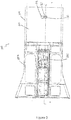
- FIGS 1 to 4 show a seating arrangement 100, in particular an aircraft seating arrangement, embodying one aspect of the invention, the seating arrangement incorporating a deployable table assembly 101 embodying another aspect of the invention.
- the deployable table assembly 101 incorporates a table 102 and a table deployment mechanism 104, which is configured to transition the table 102 between stowed and deployed positions (as shown in figures 1 and 9 respectively). This transition typically incorporates one or more intermediate positions (shown in figure 5 ) in-use.
- the seating arrangement 100 comprises at least one seat 103 and a console 105 located adjacent the seat 103.
- the seating arrangement 101 comprises two (or more) seats 103 that are side-by-side, the, or a respective, console 105 is located between adjacent seats 103.
- the table 102 preferably comprises a single leaf table; however it may alternatively comprise multiple leaves.
- the deployable table comprising the table 102 and table deployment mechanism 104 is provided within the console 105.
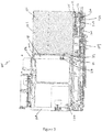
- the console 105 is preferably shaped and dimensioned to define a recess 106 therein, within which the table 102 and at least part of the table deployment mechanism 104 may be disposed when in the stowed position.
- the console 105 may incorporate one or more additional deployable table assemblies 101 such that where, for example, the seating arrangement 100 incorporates first and second seats 103 with a console 105 located therebetween (as shown in figure 8 ), each occupant may be provided with their own deployable table assembly 101, with both typically being provided within the same console 105 (see figure 8 ).
- the recess 106 typically includes an aperture 114 through which the table 102 passes when transitioning between stowed and deployed positions.
- the console 105 typically comprises a base portion 109 and an upper portion 107 with the table 102 typically being stowed in the upper portion 107, the table deployment mechanism 104 typically being provided, at least in part, in both the upper and base portions 107, 109.
- the upper portion 107 is coupled to or mounted on the base portion 109.
- the upper portion 107 is typically larger in dimension than the base portion 107, such that the upper portion 107 occupies only part of the surface area of an upper face 110 of the base portion 109, upon which the upper portion 107 is provided.
- the surface area of the upper face 110 of the base portion 109 which is not occupied by the upper portion 107 may provide an armrest or support surface for one or more objects for an occupant of the seat 103.
- the table 102 is stowed within the console 105 such that in the stowed position the table 102 is disposed substantially perpendicular to the ground surface on which the seating arrangement 100 rests during use.
- This orientation which may be referred to as a vertical orientation, is substantially perpendicular to the orientation of the table when in the deployed position (which may be referred to as a horizontal orientation).
- the table 102 may be coupled to the table deployment mechanism 104 by any suitable coupling means.
- the table deployment mechanism 104 typically comprises a carriage 112, abutment means 111, actuation means 130, and is advantageously co-operable with locking means 113 as is described in more detail hereinafter.
- the carriage 112 is movable back and forth into and out of the recess 106 via the aperture 114 in a longitudinal direction that, in preferred embodiments, is substantially parallel with the direction in which a seated passenger faces.
- the table 102 is mounted on the carriage 112 and so is movable into and out of the recess 106 via the aperture 114 in the longitudinal direction. In preferred embodiments, the table 102 is in its vertical orientation during such movement.
- the carriage 112 typically includes means for facilitating movement of the carriage such as one or more wheel(s), roller(s), rails(s) and/or slides(s). In the illustrated embodiment wheel 108 is provided for this purpose.
- the table 102 is coupled to the carriage 112 via at least one pivot means 115 such as a hinge.
- the table 102 is pivotable about the hinge such that when in the deployed position the table is disposed substantially parallel to the ground surface on which the seating arrangement 100 rests during use (as shown in figure 8 ), i.e, the table is in the horizontal orientation.
- the actuation means 130 is operable to actuate the table 102 towards a primary intermediate position in-use (not shown).
- the actuation means 130 typically comprises at least one resilient biasing means arranged to urge the table out of the recess 106 into the primary intermediate position.
- the actuation means 130 typically comprises a spring coupled to a ram.
- the actuation means 130 When the table 102 is in the stowed position the actuation means 130 is typically in a primed state.
- the actuation means 130 comprises a resilient biasing means such as a spring, this may be in a compressed state and arranged to urge the table towards the primary intermediate position. Further in the stowed position the actuation means 130 is positioned such as to abut the carriage 112.
- the actuation means 130 is typically coupled to a controller (not shown), typically comprising a user-operable latch, which upon activation is configured to release the actuation means 130 from its primed state, whereby the actuation means 130 urges the table 102 into the primary intermediate position.
- a controller typically comprising a user-operable latch, which upon activation is configured to release the actuation means 130 from its primed state, whereby the actuation means 130 urges the table 102 into the primary intermediate position.
- a user-operable latch may be coupled to the table 102 or carriage 112 to selectively prevent movement of the table under the bias of the actuation means 130 until the latch is released. In the primary intermediate position at least part of the table 102 extends out of the aperture 114 of the console 105.
- the table deployment mechanism 104 may incorporate an additional actuation means (not shown), such as a motor, which is configured to displace the table into the secondary intermediate position upon activation of the actuation means 130.
- the controller (not shown) is typically provided upon the central console 105, preferably upon the base portion 109.
- the controller is typically in mechanical or electrical communication with the actuation means 130.
- the actuation means 130 may be provided on a rear wall of the recess 106.
- the abutment means 111 may be provided on a rear portion 118 of the carriage 112, the rear portion 118 typically extending substantially perpendicular to the body of the carriage 112 in an upward direction.
- the abutment means 111 preferably comprises a spring 117 coupled to a lever 119. In the stowed position, the lever 119 and the rear portion 118 provide an elongate supporting edge. In the stowed position the abutment means 111 is typically in a primed state. For example where the abutment means 111 comprises a resilient biasing means such as a spring, this may be in a compressed state. Further in the stowed position the abutment means 111 is positioned such as to abut the table 102.
- the rear portion 118 of the carriage 112 is adapted to substantially occupy the dimensions of the aperture 114 of the console 105.
- the lever 119 is adapted to extend out of, at least in part, the aperture 114 in-use.
- the abutment means 111 is typically pivotably coupled to a pin 133, which is extendable into a cavity 134.
- the pin 133 typically extends substantially through the carriage 112, in a downward direction.
- the cavity 134 is shaped and dimensioned to receive the pin 133 such that the pin 133 is operable to releasably engage the cavity 134 when the deployable table 101 is in the deployed position.
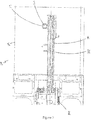
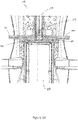
- the table 102 is pivotable about a horizontal axis extending in the longitudinal direction when in the secondary intermediate position (as shown in figure 5 ), where the horizontal axis is to be understood to comprise the axis extending longitudinally substantially parallel with the ground surface upon which the seating arrangement 101 rests during use.
- the table 102 is configured to pivot through approximately 90° from its secondary intermediate position to its deployed position such that the table 102, when pivoted into the deployed position is substantially horizontally disposed and extends across the respective seat 103 (i.e. in front of a seated passenger in use).
- the table 102 is preferably configured to pivot only in one direction from the secondary intermediate position and, to this end, the pivot means 115, which typically comprises a hinge, may include a stop for preventing the table 102 from pivoting in the opposite direction relative to the seat 103.
- the pivot means 115 for each table 102 provided within the console 105 are configured to pivot in opposing directions when transitioning from the secondary intermediate position to the deployment position (as shown in Figure 8 ).
- the lever 119 of the abutment means 111 is configured to pivot out of the aperture 114 in a substantially longitudinal direction in-use into an extended position (as shown in figure 8 ).
- the pin 133 is configured to extend in a substantially lateral direction to releasably engage the cavity 134.
- this engagement is operable to lock the abutment means 111 in the extended position in-use.
- the abutment means 111 is configured to prevent movement of the table 102 in the longitudinal direction in-use.
- the abutment means 111 is further configured such that when the table 102 is pivoted back into the secondary intermediate position, the in-use topside of the table 102 is operable to abut the lever 119 of the abutment means 111.
- the lever 119 is operable to retract into the recess 10 upon contact with the table 102, to this end the lever 119 is chamfered such as to provide a substantially round peripheral edge,
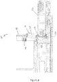
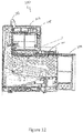
- Locking means 113 preferably comprising an extendable latch 126, is configured to releasably engage the carriage 112 when the table 102 is in the deployed position.
- the latch 126 is provided on the base portion 109 of the console 105 in the region in front of the upper portion 107.
- the latch 126 is movable between a retracted state (see for example figure 2 ) in which it is located within the console 105 (preferably such that its upper surface is substantially flush with the upper surface 110 of the console 105) and an extended state (see for example figure 6 ) in which it projects upwardly from the upper surface 110 of the console 105), typically through an aperture 127 formed in the surface 110.
- the carriage 112 includes a corresponding latch-receiving recess 122 in its underside, in which the latch 126 is located in its extended state, i.e. when the locking means is engaged.
- the arrangement is such that the latch 126 and the recess 122 are aligned with one another when the table 102 is in its secondary intermediate position (and also the deployed position).
- the locking means 113 is provided on the console 105 and, when the latch 126 is engaged with the carriage, prevents relative movement between the carriage 112 and the console 105 in a lateral direction at least, the lateral direction being perpendicular to the longitudinal direction, i.e. a direction that is transverse with respect to the seat 103.
- this engagement prevents lateral movement of the table 102 relative to the console 105.
- the locking means 113 is coupled to or otherwise co-operable with the carriage 112 such that movement of the carriage 112 into the secondary intermediate state causes the latch 126 to adopt its extended state.
- the locking means 113 is preferably also coupled to or otherwise co-operable with the carriage 112 such that movement of the carriage 112 from the secondary intermediate state towards the stowed position causes the latch 126 to adopt its retracted state.
- the locking means 113 includes a linkage mechanism 123 that couples the carriage 112 to the latch 126 in order to actuate the latch 126 from the retracted state to the extended state in response to movement of the carriage 112, from the first intermediate position to the second intermediate position.
- the linkage mechanism 123 couples with a part 129 of the carriage 112 that is located below the surface 110. The coupling may be fixed (e.g. by means of a cable (not shown)) or may involve engagement of the part 129 and the linkage mechanism 123 as the carriage 112 moves towards the secondary intermediate position.
- the linkage mechanism 123 includes a linkage 124 that is pivotably coupled to the console 105 and to the latch 126 in order to translate movement of the carriage 112 in the longitudinal direction into upwards movement of the latch 126.
- the illustrated linkage mechanism 123 includes a linkage member 120 that couples between the linkage 124 to the carriage part 129 in order to pivot the linkage 124 in response to movement of the carriage 112 towards the secondary intermediate position thereby moving the latch 126 to its engaged state.
- the preferred arrangement is such that the latch 126 is actuated into its engaged state at substantially the same time as the carriage 112 reaches the secondary intermediate position.
- the latch 126 is moved to its retracted state by engagement with the carriage 112 as the carriage moves from the secondary intermediate state to the stowed position.
- This may be achieved by providing the foremost (in the longitudinal direction) surface of the latch 126 and/or the foremost surface of the recess 122 with a shape that causes the latch 126 to be pushed downwards when the recess 122 engages with the latch 126 as the carriage moves from the secondary intermediate state to the stowed position.
- the foremost surface 131 of the recess 122 is oblique with respect to the direction of movement of the carriage such that it pushes the latch 126 downwards when the carriage moves.
- the locking means 113 is conveniently provided within the console 105, typically within the base portion 109 and is configured to extend therefrom. Typically the locking means 113, and more particularly the latch 126, extends from the upper face 110 of the base portion 109 in-use. In the stowed position the latch 126 is preferably retracted within the base portion 109, such that it is substantially flush with the upper face 110 (as shown in figures 2 to 4 ).
- the linkages 120, 124 may comprise one or more connecting rods comprising metal and/or plastic and/or a composite material or any other suitable material.
- the linkages 120, 124 may incorporate one or more resilient biasing means, such as a spring, to assist movement of the latch 126 into and/or out of its extended state.
- the linkage 120 may comprise a rod, optionally incorporating biasing means, which is coupled to the carriage 112 at one end and to one end of the pivotable linkage 124 at the other.
- the other end of the linkage 124 is coupled to the latch 126, e.g. by a further link 133, such that the linkage 124, when pivoted, extends the latch 126.
- the linkage, or lever, 124 is pivotably coupled to the base portion 109, such that the displacement of the rod 122 in the longitudinal (or forward) direction causes pivoting movement of the lever 124.
- one or more support members 116 are provided for supporting the table 102 on the upper surface 110 when in the deployed position.
- the or each support member 116 which may take the form of a leg or other projection, is provided on the in-use underside of the table 102 and may be retractable into or foldable against the underside of the table 112. As such, the support member 116 is deployable between a use position in which it projects from the underside of the table and a stowed position in which it is located in or against said table.
- The, or each, support member 116 is configured such that when the deployable table 101 is in the stowed position, the support member 116 is folded against the table 102, preferably substantially flat against the underside (as shown in figure 10 ), or retracted into the table. Further advantageously, the, or each, support member 116 is configured such that when the deployable table 101 is in the deployed position the support member 116 extends substantially perpendicular to the table 102, whereby it is configured to rest upon the base portion 109, preferably upon the upper face 110 thereof (as shown in figures 8 and 9 ). The, or each, support member 116 may be resiliently biased to adopt its use position such that the use position is adopted as the table emerges from the recess 106.
- the table 102 moves to the primary intermediate position (as shown in figures 1 to 4 ).
- the table 102 may then be pulled by the user into the secondary intermediate position (as shown in figures 5 to 7 ).
- the forward movement of the carriage 112 operates the locking means 113 causing the latch 12 to extend from the console 105 into the recess 122.
- the table 102 is pivotable about the pivot means 115 into the deployed position (as shown in Figure 8 ) whereupon the abutment means 111 is configured to releasably lock in an extended position.
- the locking means 113 provides stability, in particular by preventing or at least restricting lateral movement of the table 102. Stability is further enhanced by the support member 116. Tables embodying the invention can therefore be easily deployed and stowed and are stable in use.
Landscapes
- Engineering & Computer Science (AREA)
- Aviation & Aerospace Engineering (AREA)
- Transportation (AREA)
- Mechanical Engineering (AREA)
- Passenger Equipment (AREA)
Applications Claiming Priority (1)
| Application Number | Priority Date | Filing Date | Title |
|---|---|---|---|
| GB1602498.6A GB2547245B (en) | 2016-02-11 | 2016-02-11 | Deployable table |
Publications (2)
| Publication Number | Publication Date |
|---|---|
| EP3205579A1 true EP3205579A1 (de) | 2017-08-16 |
| EP3205579B1 EP3205579B1 (de) | 2020-09-02 |
Family
ID=55697582
Family Applications (1)
| Application Number | Title | Priority Date | Filing Date |
|---|---|---|---|
| EP17155507.1A Active EP3205579B1 (de) | 2016-02-11 | 2017-02-09 | Aufklappbarer tisch |
Country Status (3)
| Country | Link |
|---|---|
| US (1) | US10569883B2 (de) |
| EP (1) | EP3205579B1 (de) |
| GB (1) | GB2547245B (de) |
Families Citing this family (2)
| Publication number | Priority date | Publication date | Assignee | Title |
|---|---|---|---|---|
| US10730627B2 (en) * | 2015-04-13 | 2020-08-04 | Safran Seats | Seat module comprising an armrest with an optimised design |
| US10889377B1 (en) * | 2019-06-28 | 2021-01-12 | B/E Aerospace, Inc. | Braking aircraft table system |
Citations (6)
| Publication number | Priority date | Publication date | Assignee | Title |
|---|---|---|---|---|
| WO2011063399A2 (en) * | 2009-11-23 | 2011-05-26 | Weber Aircraft Llc | Table stop assembly |
| US20120133180A1 (en) * | 2010-11-30 | 2012-05-31 | Be Aerospace, Inc. | Stowable passenger seat tray table |
| WO2013030797A1 (en) * | 2011-09-02 | 2013-03-07 | Societe Industrielle Et Commerciale De Materiel Aeronautique | Premium seat comprising a stowable food tray and a sliding armrest |
| US20140300147A1 (en) * | 2013-04-04 | 2014-10-09 | B/E Aerospace, Inc. | Passenger seat with drop-down armrest assembly |
| EP2930111A1 (de) * | 2014-04-07 | 2015-10-14 | Zodiac Seats UK Limited | Tischanordnung |
| EP2930112A1 (de) * | 2014-04-07 | 2015-10-14 | Zodiac Seats UK Limited | Tischanordnung |
Family Cites Families (7)
| Publication number | Priority date | Publication date | Assignee | Title |
|---|---|---|---|---|
| US3632161A (en) * | 1970-07-13 | 1972-01-04 | Universal Oil Prod Co | Side arm stowable table |
| US4834449A (en) * | 1988-04-18 | 1989-05-30 | Fred Engelman | Collapsible table assembly |
| US5050929A (en) * | 1989-10-24 | 1991-09-24 | Gueringer John M | Auxiliary furniture tray system |
| DE19705754A1 (de) * | 1997-02-14 | 1998-08-20 | Schaltbau Ag | Klapptisch für einen Sitzplatz in einem Fahrzeug |
| DE10034477B4 (de) * | 2000-07-15 | 2006-06-29 | Marlene Schneppendahl | Versenkbarer Klapptisch |
| US8205563B2 (en) * | 2009-06-29 | 2012-06-26 | St. Louis Designs, Inc. | Aircraft table system with rolling sled member |
| JP6139016B2 (ja) * | 2013-04-04 | 2017-05-31 | ビーイー・エアロスペース・インコーポレーテッドB/E Aerospace, Inc. | 並進移動を含む、垂直に収納されるトレーテーブルアセンブリ |
-
2016
- 2016-02-11 GB GB1602498.6A patent/GB2547245B/en active Active
-
2017
- 2017-02-09 EP EP17155507.1A patent/EP3205579B1/de active Active
- 2017-02-10 US US15/429,880 patent/US10569883B2/en active Active
Patent Citations (6)
| Publication number | Priority date | Publication date | Assignee | Title |
|---|---|---|---|---|
| WO2011063399A2 (en) * | 2009-11-23 | 2011-05-26 | Weber Aircraft Llc | Table stop assembly |
| US20120133180A1 (en) * | 2010-11-30 | 2012-05-31 | Be Aerospace, Inc. | Stowable passenger seat tray table |
| WO2013030797A1 (en) * | 2011-09-02 | 2013-03-07 | Societe Industrielle Et Commerciale De Materiel Aeronautique | Premium seat comprising a stowable food tray and a sliding armrest |
| US20140300147A1 (en) * | 2013-04-04 | 2014-10-09 | B/E Aerospace, Inc. | Passenger seat with drop-down armrest assembly |
| EP2930111A1 (de) * | 2014-04-07 | 2015-10-14 | Zodiac Seats UK Limited | Tischanordnung |
| EP2930112A1 (de) * | 2014-04-07 | 2015-10-14 | Zodiac Seats UK Limited | Tischanordnung |
Also Published As
| Publication number | Publication date |
|---|---|
| GB2547245B (en) | 2020-01-22 |
| EP3205579B1 (de) | 2020-09-02 |
| US20170233078A1 (en) | 2017-08-17 |
| US10569883B2 (en) | 2020-02-25 |
| GB201602498D0 (en) | 2016-03-30 |
| GB2547245A (en) | 2017-08-16 |
Similar Documents
| Publication | Publication Date | Title |
|---|---|---|
| JP4434075B2 (ja) | 車両用シートの移動装置 | |
| EP1393968B1 (de) | Fahrzeugsitz | |
| US10279912B2 (en) | Passenger seating with partition assembly | |
| DE102013225832B4 (de) | Falt- und klappanordnung für eine fahrzeugsitzanordnung | |
| US11001172B2 (en) | Retractable tray device for vehicle seat | |
| CN101992702B (zh) | 车辆座椅,特别是机动车辆座椅 | |
| EP3227183B1 (de) | Tischeinheit | |
| CN102555857B (zh) | 用于车辆座椅的折叠下俯式装置 | |
| JP2017210138A (ja) | 車両用シート | |
| CN101193771A (zh) | 单腿转换座椅 | |
| US11091071B2 (en) | Seat provided with a system for locking the tray table in the event of an impact | |
| EP3335931B1 (de) | Ausfahrbare fussstützenanordnung | |
| CN110979117A (zh) | 一组座椅及包括该组座椅的机动车辆 | |
| EP3205579B1 (de) | Aufklappbarer tisch | |
| US7455342B2 (en) | Stowable ottoman for a vehicle passenger cabin | |
| JP2013112127A (ja) | 車両用シート | |
| CN211765095U (zh) | 用于车辆的座椅总成 | |
| US20120319450A1 (en) | Retractable striker and seat with a retractable striker | |
| KR101669761B1 (ko) | 자동차 시트의 워크인 복원장치 | |
| US11958614B2 (en) | Seat, in particular for an aircraft, with a single actuator | |
| US20070046078A1 (en) | Stowage of barstool(s) by mechanical movement of the barstool(s) on bar counters in an aircraft cabin | |
| JP6234949B2 (ja) | 乗物用シートのテーブル装置 | |
| CN109435797B (zh) | 一种多连杆折叠机构以及由此构成的汽车座椅 | |
| US20170190267A1 (en) | Stowable seats | |
| JP6167973B2 (ja) | 乗物用シートのテーブル |
Legal Events
| Date | Code | Title | Description |
|---|---|---|---|
| PUAI | Public reference made under article 153(3) epc to a published international application that has entered the european phase |
Free format text: ORIGINAL CODE: 0009012 |
|
| STAA | Information on the status of an ep patent application or granted ep patent |
Free format text: STATUS: THE APPLICATION HAS BEEN PUBLISHED |
|
| AK | Designated contracting states |
Kind code of ref document: A1 Designated state(s): AL AT BE BG CH CY CZ DE DK EE ES FI FR GB GR HR HU IE IS IT LI LT LU LV MC MK MT NL NO PL PT RO RS SE SI SK SM TR |
|
| AX | Request for extension of the european patent |
Extension state: BA ME |
|
| STAA | Information on the status of an ep patent application or granted ep patent |
Free format text: STATUS: REQUEST FOR EXAMINATION WAS MADE |
|
| 17P | Request for examination filed |
Effective date: 20180215 |
|
| RBV | Designated contracting states (corrected) |
Designated state(s): AL AT BE BG CH CY CZ DE DK EE ES FI FR GB GR HR HU IE IS IT LI LT LU LV MC MK MT NL NO PL PT RO RS SE SI SK SM TR |
|
| GRAP | Despatch of communication of intention to grant a patent |
Free format text: ORIGINAL CODE: EPIDOSNIGR1 |
|
| STAA | Information on the status of an ep patent application or granted ep patent |
Free format text: STATUS: GRANT OF PATENT IS INTENDED |
|
| INTG | Intention to grant announced |
Effective date: 20200318 |
|
| GRAS | Grant fee paid |
Free format text: ORIGINAL CODE: EPIDOSNIGR3 |
|
| GRAA | (expected) grant |
Free format text: ORIGINAL CODE: 0009210 |
|
| STAA | Information on the status of an ep patent application or granted ep patent |
Free format text: STATUS: THE PATENT HAS BEEN GRANTED |
|
| AK | Designated contracting states |
Kind code of ref document: B1 Designated state(s): AL AT BE BG CH CY CZ DE DK EE ES FI FR GB GR HR HU IE IS IT LI LT LU LV MC MK MT NL NO PL PT RO RS SE SI SK SM TR |
|
| REG | Reference to a national code |
Ref country code: GB Ref legal event code: FG4D |
|
| REG | Reference to a national code |
Ref country code: AT Ref legal event code: REF Ref document number: 1308541 Country of ref document: AT Kind code of ref document: T Effective date: 20200915 Ref country code: CH Ref legal event code: EP |
|
| REG | Reference to a national code |
Ref country code: DE Ref legal event code: R096 Ref document number: 602017022594 Country of ref document: DE |
|
| REG | Reference to a national code |
Ref country code: IE Ref legal event code: FG4D |
|
| REG | Reference to a national code |
Ref country code: LT Ref legal event code: MG4D |
|
| PG25 | Lapsed in a contracting state [announced via postgrant information from national office to epo] |
Ref country code: LT Free format text: LAPSE BECAUSE OF FAILURE TO SUBMIT A TRANSLATION OF THE DESCRIPTION OR TO PAY THE FEE WITHIN THE PRESCRIBED TIME-LIMIT Effective date: 20200902 Ref country code: HR Free format text: LAPSE BECAUSE OF FAILURE TO SUBMIT A TRANSLATION OF THE DESCRIPTION OR TO PAY THE FEE WITHIN THE PRESCRIBED TIME-LIMIT Effective date: 20200902 Ref country code: BG Free format text: LAPSE BECAUSE OF FAILURE TO SUBMIT A TRANSLATION OF THE DESCRIPTION OR TO PAY THE FEE WITHIN THE PRESCRIBED TIME-LIMIT Effective date: 20201202 Ref country code: FI Free format text: LAPSE BECAUSE OF FAILURE TO SUBMIT A TRANSLATION OF THE DESCRIPTION OR TO PAY THE FEE WITHIN THE PRESCRIBED TIME-LIMIT Effective date: 20200902 Ref country code: GR Free format text: LAPSE BECAUSE OF FAILURE TO SUBMIT A TRANSLATION OF THE DESCRIPTION OR TO PAY THE FEE WITHIN THE PRESCRIBED TIME-LIMIT Effective date: 20201203 Ref country code: NO Free format text: LAPSE BECAUSE OF FAILURE TO SUBMIT A TRANSLATION OF THE DESCRIPTION OR TO PAY THE FEE WITHIN THE PRESCRIBED TIME-LIMIT Effective date: 20201202 Ref country code: SE Free format text: LAPSE BECAUSE OF FAILURE TO SUBMIT A TRANSLATION OF THE DESCRIPTION OR TO PAY THE FEE WITHIN THE PRESCRIBED TIME-LIMIT Effective date: 20200902 |
|
| REG | Reference to a national code |
Ref country code: NL Ref legal event code: MP Effective date: 20200902 |
|
| REG | Reference to a national code |
Ref country code: AT Ref legal event code: MK05 Ref document number: 1308541 Country of ref document: AT Kind code of ref document: T Effective date: 20200902 |
|
| PG25 | Lapsed in a contracting state [announced via postgrant information from national office to epo] |
Ref country code: RS Free format text: LAPSE BECAUSE OF FAILURE TO SUBMIT A TRANSLATION OF THE DESCRIPTION OR TO PAY THE FEE WITHIN THE PRESCRIBED TIME-LIMIT Effective date: 20200902 Ref country code: PL Free format text: LAPSE BECAUSE OF FAILURE TO SUBMIT A TRANSLATION OF THE DESCRIPTION OR TO PAY THE FEE WITHIN THE PRESCRIBED TIME-LIMIT Effective date: 20200902 Ref country code: LV Free format text: LAPSE BECAUSE OF FAILURE TO SUBMIT A TRANSLATION OF THE DESCRIPTION OR TO PAY THE FEE WITHIN THE PRESCRIBED TIME-LIMIT Effective date: 20200902 |
|
| PG25 | Lapsed in a contracting state [announced via postgrant information from national office to epo] |
Ref country code: SM Free format text: LAPSE BECAUSE OF FAILURE TO SUBMIT A TRANSLATION OF THE DESCRIPTION OR TO PAY THE FEE WITHIN THE PRESCRIBED TIME-LIMIT Effective date: 20200902 Ref country code: EE Free format text: LAPSE BECAUSE OF FAILURE TO SUBMIT A TRANSLATION OF THE DESCRIPTION OR TO PAY THE FEE WITHIN THE PRESCRIBED TIME-LIMIT Effective date: 20200902 Ref country code: RO Free format text: LAPSE BECAUSE OF FAILURE TO SUBMIT A TRANSLATION OF THE DESCRIPTION OR TO PAY THE FEE WITHIN THE PRESCRIBED TIME-LIMIT Effective date: 20200902 Ref country code: PT Free format text: LAPSE BECAUSE OF FAILURE TO SUBMIT A TRANSLATION OF THE DESCRIPTION OR TO PAY THE FEE WITHIN THE PRESCRIBED TIME-LIMIT Effective date: 20210104 Ref country code: CZ Free format text: LAPSE BECAUSE OF FAILURE TO SUBMIT A TRANSLATION OF THE DESCRIPTION OR TO PAY THE FEE WITHIN THE PRESCRIBED TIME-LIMIT Effective date: 20200902 |
|
| PG25 | Lapsed in a contracting state [announced via postgrant information from national office to epo] |
Ref country code: AL Free format text: LAPSE BECAUSE OF FAILURE TO SUBMIT A TRANSLATION OF THE DESCRIPTION OR TO PAY THE FEE WITHIN THE PRESCRIBED TIME-LIMIT Effective date: 20200902 Ref country code: AT Free format text: LAPSE BECAUSE OF FAILURE TO SUBMIT A TRANSLATION OF THE DESCRIPTION OR TO PAY THE FEE WITHIN THE PRESCRIBED TIME-LIMIT Effective date: 20200902 Ref country code: ES Free format text: LAPSE BECAUSE OF FAILURE TO SUBMIT A TRANSLATION OF THE DESCRIPTION OR TO PAY THE FEE WITHIN THE PRESCRIBED TIME-LIMIT Effective date: 20200902 Ref country code: IS Free format text: LAPSE BECAUSE OF FAILURE TO SUBMIT A TRANSLATION OF THE DESCRIPTION OR TO PAY THE FEE WITHIN THE PRESCRIBED TIME-LIMIT Effective date: 20210102 |
|
| REG | Reference to a national code |
Ref country code: DE Ref legal event code: R097 Ref document number: 602017022594 Country of ref document: DE |
|
| PG25 | Lapsed in a contracting state [announced via postgrant information from national office to epo] |
Ref country code: SK Free format text: LAPSE BECAUSE OF FAILURE TO SUBMIT A TRANSLATION OF THE DESCRIPTION OR TO PAY THE FEE WITHIN THE PRESCRIBED TIME-LIMIT Effective date: 20200902 |
|
| PLBE | No opposition filed within time limit |
Free format text: ORIGINAL CODE: 0009261 |
|
| STAA | Information on the status of an ep patent application or granted ep patent |
Free format text: STATUS: NO OPPOSITION FILED WITHIN TIME LIMIT |
|
| 26N | No opposition filed |
Effective date: 20210603 |
|
| PG25 | Lapsed in a contracting state [announced via postgrant information from national office to epo] |
Ref country code: SI Free format text: LAPSE BECAUSE OF FAILURE TO SUBMIT A TRANSLATION OF THE DESCRIPTION OR TO PAY THE FEE WITHIN THE PRESCRIBED TIME-LIMIT Effective date: 20200902 Ref country code: DK Free format text: LAPSE BECAUSE OF FAILURE TO SUBMIT A TRANSLATION OF THE DESCRIPTION OR TO PAY THE FEE WITHIN THE PRESCRIBED TIME-LIMIT Effective date: 20200902 |
|
| PG25 | Lapsed in a contracting state [announced via postgrant information from national office to epo] |
Ref country code: MC Free format text: LAPSE BECAUSE OF FAILURE TO SUBMIT A TRANSLATION OF THE DESCRIPTION OR TO PAY THE FEE WITHIN THE PRESCRIBED TIME-LIMIT Effective date: 20200902 |
|
| REG | Reference to a national code |
Ref country code: BE Ref legal event code: MM Effective date: 20210228 |
|
| PG25 | Lapsed in a contracting state [announced via postgrant information from national office to epo] |
Ref country code: CH Free format text: LAPSE BECAUSE OF NON-PAYMENT OF DUE FEES Effective date: 20210228 Ref country code: LU Free format text: LAPSE BECAUSE OF NON-PAYMENT OF DUE FEES Effective date: 20210209 Ref country code: LI Free format text: LAPSE BECAUSE OF NON-PAYMENT OF DUE FEES Effective date: 20210228 |
|
| PG25 | Lapsed in a contracting state [announced via postgrant information from national office to epo] |
Ref country code: IE Free format text: LAPSE BECAUSE OF NON-PAYMENT OF DUE FEES Effective date: 20210209 |
|
| PG25 | Lapsed in a contracting state [announced via postgrant information from national office to epo] |
Ref country code: BE Free format text: LAPSE BECAUSE OF NON-PAYMENT OF DUE FEES Effective date: 20210228 |
|
| PG25 | Lapsed in a contracting state [announced via postgrant information from national office to epo] |
Ref country code: HU Free format text: LAPSE BECAUSE OF FAILURE TO SUBMIT A TRANSLATION OF THE DESCRIPTION OR TO PAY THE FEE WITHIN THE PRESCRIBED TIME-LIMIT; INVALID AB INITIO Effective date: 20170209 |
|
| PG25 | Lapsed in a contracting state [announced via postgrant information from national office to epo] |
Ref country code: NL Free format text: LAPSE BECAUSE OF NON-PAYMENT OF DUE FEES Effective date: 20200923 Ref country code: CY Free format text: LAPSE BECAUSE OF FAILURE TO SUBMIT A TRANSLATION OF THE DESCRIPTION OR TO PAY THE FEE WITHIN THE PRESCRIBED TIME-LIMIT Effective date: 20200902 |
|
| PG25 | Lapsed in a contracting state [announced via postgrant information from national office to epo] |
Ref country code: MK Free format text: LAPSE BECAUSE OF FAILURE TO SUBMIT A TRANSLATION OF THE DESCRIPTION OR TO PAY THE FEE WITHIN THE PRESCRIBED TIME-LIMIT Effective date: 20200902 |
|
| PG25 | Lapsed in a contracting state [announced via postgrant information from national office to epo] |
Ref country code: MT Free format text: LAPSE BECAUSE OF FAILURE TO SUBMIT A TRANSLATION OF THE DESCRIPTION OR TO PAY THE FEE WITHIN THE PRESCRIBED TIME-LIMIT Effective date: 20200902 |
|
| PGFP | Annual fee paid to national office [announced via postgrant information from national office to epo] |
Ref country code: DE Payment date: 20250218 Year of fee payment: 9 |
|
| PGFP | Annual fee paid to national office [announced via postgrant information from national office to epo] |
Ref country code: FR Payment date: 20250221 Year of fee payment: 9 |
|
| PGFP | Annual fee paid to national office [announced via postgrant information from national office to epo] |
Ref country code: GB Payment date: 20250110 Year of fee payment: 9 Ref country code: IT Payment date: 20250221 Year of fee payment: 9 |
|
| PG25 | Lapsed in a contracting state [announced via postgrant information from national office to epo] |
Ref country code: TR Free format text: LAPSE BECAUSE OF FAILURE TO SUBMIT A TRANSLATION OF THE DESCRIPTION OR TO PAY THE FEE WITHIN THE PRESCRIBED TIME-LIMIT Effective date: 20200902 |