US10476335B2 - Electric machine - Google Patents
Electric machine Download PDFInfo
- Publication number
- US10476335B2 US10476335B2 US15/328,745 US201515328745A US10476335B2 US 10476335 B2 US10476335 B2 US 10476335B2 US 201515328745 A US201515328745 A US 201515328745A US 10476335 B2 US10476335 B2 US 10476335B2
- Authority
- US
- United States
- Prior art keywords
- stator
- coils
- rotor
- electric machine
- electric
- Prior art date
- Legal status (The legal status is an assumption and is not a legal conclusion. Google has not performed a legal analysis and makes no representation as to the accuracy of the status listed.)
- Active, expires
Links
- 238000004804 winding Methods 0.000 claims abstract description 45
- 230000033001 locomotion Effects 0.000 claims description 11
- 238000005516 engineering process Methods 0.000 abstract description 5
- 229910000831 Steel Inorganic materials 0.000 description 6
- 239000010959 steel Substances 0.000 description 6
- 230000005405 multipole Effects 0.000 description 3
- 238000005265 energy consumption Methods 0.000 description 2
- 230000006698 induction Effects 0.000 description 2
- 239000000463 material Substances 0.000 description 2
- 238000010276 construction Methods 0.000 description 1
- 230000003247 decreasing effect Effects 0.000 description 1
- 230000001419 dependent effect Effects 0.000 description 1
- 230000005284 excitation Effects 0.000 description 1
- 230000004907 flux Effects 0.000 description 1
- 230000003993 interaction Effects 0.000 description 1
- 230000014759 maintenance of location Effects 0.000 description 1
- 238000011089 mechanical engineering Methods 0.000 description 1
- 230000003068 static effect Effects 0.000 description 1
- 230000001360 synchronised effect Effects 0.000 description 1
Images


Classifications
-
- H—ELECTRICITY
- H02—GENERATION; CONVERSION OR DISTRIBUTION OF ELECTRIC POWER
- H02K—DYNAMO-ELECTRIC MACHINES
- H02K3/00—Details of windings
- H02K3/04—Windings characterised by the conductor shape, form or construction, e.g. with bar conductors
- H02K3/28—Layout of windings or of connections between windings
-
- H—ELECTRICITY
- H02—GENERATION; CONVERSION OR DISTRIBUTION OF ELECTRIC POWER
- H02K—DYNAMO-ELECTRIC MACHINES
- H02K11/00—Structural association of dynamo-electric machines with electric components or with devices for shielding, monitoring or protection
- H02K11/30—Structural association with control circuits or drive circuits
- H02K11/33—Drive circuits, e.g. power electronics
-
- H—ELECTRICITY
- H02—GENERATION; CONVERSION OR DISTRIBUTION OF ELECTRIC POWER
- H02K—DYNAMO-ELECTRIC MACHINES
- H02K17/00—Asynchronous induction motors; Asynchronous induction generators
- H02K17/02—Asynchronous induction motors
- H02K17/16—Asynchronous induction motors having rotors with internally short-circuited windings, e.g. cage rotors
- H02K17/165—Asynchronous induction motors having rotors with internally short-circuited windings, e.g. cage rotors characterised by the squirrel-cage or other short-circuited windings
-
- H—ELECTRICITY
- H02—GENERATION; CONVERSION OR DISTRIBUTION OF ELECTRIC POWER
- H02K—DYNAMO-ELECTRIC MACHINES
- H02K17/00—Asynchronous induction motors; Asynchronous induction generators
- H02K17/02—Asynchronous induction motors
- H02K17/26—Asynchronous induction motors having rotors or stators designed to permit synchronous operation
-
- H—ELECTRICITY
- H02—GENERATION; CONVERSION OR DISTRIBUTION OF ELECTRIC POWER
- H02K—DYNAMO-ELECTRIC MACHINES
- H02K21/00—Synchronous motors having permanent magnets; Synchronous generators having permanent magnets
- H02K21/12—Synchronous motors having permanent magnets; Synchronous generators having permanent magnets with stationary armatures and rotating magnets
- H02K21/14—Synchronous motors having permanent magnets; Synchronous generators having permanent magnets with stationary armatures and rotating magnets with magnets rotating within the armatures
-
- H—ELECTRICITY
- H02—GENERATION; CONVERSION OR DISTRIBUTION OF ELECTRIC POWER
- H02K—DYNAMO-ELECTRIC MACHINES
- H02K7/00—Arrangements for handling mechanical energy structurally associated with dynamo-electric machines, e.g. structural association with mechanical driving motors or auxiliary dynamo-electric machines
- H02K7/06—Means for converting reciprocating motion into rotary motion or vice versa
-
- H—ELECTRICITY
- H02—GENERATION; CONVERSION OR DISTRIBUTION OF ELECTRIC POWER
- H02P—CONTROL OR REGULATION OF ELECTRIC MOTORS, ELECTRIC GENERATORS OR DYNAMO-ELECTRIC CONVERTERS; CONTROLLING TRANSFORMERS, REACTORS OR CHOKE COILS
- H02P7/00—Arrangements for regulating or controlling the speed or torque of electric DC motors
- H02P7/06—Arrangements for regulating or controlling the speed or torque of electric DC motors for regulating or controlling an individual dc dynamo-electric motor by varying field or armature current
-
- H—ELECTRICITY
- H02—GENERATION; CONVERSION OR DISTRIBUTION OF ELECTRIC POWER
- H02K—DYNAMO-ELECTRIC MACHINES
- H02K19/00—Synchronous motors or generators
- H02K19/16—Synchronous generators
- H02K19/18—Synchronous generators having windings each turn of which co-operates only with poles of one polarity, e.g. homopolar generators
- H02K19/20—Synchronous generators having windings each turn of which co-operates only with poles of one polarity, e.g. homopolar generators with variable-reluctance soft-iron rotors without winding
-
- H—ELECTRICITY
- H02—GENERATION; CONVERSION OR DISTRIBUTION OF ELECTRIC POWER
- H02K—DYNAMO-ELECTRIC MACHINES
- H02K2201/00—Specific aspects not provided for in the other groups of this subclass relating to the magnetic circuits
- H02K2201/03—Machines characterised by aspects of the air-gap between rotor and stator
Definitions
- the invention described herein belongs to the electric motor and power generator category and may be used to generate electric and/or mechanical energy, to convert electric energy into mechanical energy and vice versa, etc.
- This electric machine is environmentally friendly and may be used in the power industry, the transport industry, mechanical engineering, the construction industry, astronautics, and other fields of technology.
- Commutator machines include universal electric machines and direct current machines, for example, those with permanent magnets and excitation winding.
- Commutatorless machines include synchronous and asynchronous electric machines, for example, those with squirrel-cage and phase-wound rotor, single-phase, three-phase, capacitor-type, reactive, hysteresis-type, linear and brushless rotor.
- the brushless motors that include a rotor and a stator with their coils (phases) connected in parallel and have a thyristor (controlled) current feed to stator coils.
- Phase machines are based on a relatively simple principle of operation: at first, maximum electric current is supplied to the first phase (a coil, or a system of coils), which makes the rotor turn by a certain angle. Then, similarly, maximum electric current is supplied to the second phase (a coil, or a system of coils). The rotor turns by a certain angle again, etc.
- electric current in the previous phase[s] coil[s]
- such a design does function, but is not optimal: not all the coils operate at full capacity at any moment.
- this electric machine may be used as an electric motor, a power generator, an electric motor-generator; in particular, it may be used as an electric DC transformer, wherein an electric motor fed by an alternating electric current rotates an electric generator that feeds direct electric current into an external two-wire grid (or vice versa).
- an electric machine that comprises a rotor and a stator with stator winding coils and a control device.
- the stator winding coils are made as a system of radial and/or tangential coils connected in series and/or back-to-back; each of the coils have terminals, and the control device can connect its electric contacts to the terminals of the corresponding coils in order to provide a chain control of electric current supply to the corresponding stator coils and thus to create, at each point in time, a pre-determined stator magnetic field in the electric machine, whether a rotating, or a reciprocating one, depending on the spatial position and the magnetic condition of the rotor that performs rotating, or reciprocating motions.
- a chain is a multitude of stator coils connected to one another in some manner, including by means of a control device.
- Chain control is control by means of a control device, when connects to the chain, as it exists at any particular moment (herewith the chain consists of two or more stator coils connected in series and/or back-to-back and each of the coils have electric current of a predetermined direction): 1) one, or more radial stator coils, or 2) if required, one or more tangential stator coils, or 3) if required, two, or more tangential and radial stator coils, 4) while other stator coil(s) may be simultaneously disconnected from this chain.
- each of the coils so connected to the control device must have electric terminals (contacts) to enable its connection to (disconnection from) the previously mentioned chain by means of the control device. Therefore, chain control may arrange a corresponding motion of the stator magnetic field by controlling the electric current feed into the corresponding stator coils.
- the above definition of chain control involves the properties of a control device which are not considered herein; average existing technology allows creating such devices with such properties.
- stator magnetic field can be rotated depending on the spatial position and the magnetic condition of the rotor that performs rotating (see ibid., pp. 313-314), or reciprocating motions.
- control systems may manage the operation of machinery, gear, vehicles, etc. (see ibid., pp.
- chain control opens a very broad range of rotor motion control possibilities in an electric machine, such as: rotating (including with variable frequency), reciprocating (including with variable frequency), frequent starts and stops, intermittent motion, back-and-forth rotation, retention of the rotor at a given angular direction, etc.
- rotating including with variable frequency
- reciprocating including with variable frequency
- intermittent motion including with variable frequency
- back-and-forth rotation retention of the rotor at a given angular direction, etc.
- the electric machine described herein is multifunctional and can be designed in different variations.
- the proposed device shall have the following distinct features: firstly, an enhanced concentration of the magnetic flux of the stator core (due to the radial width of the stator core) in the rotor of the electric machine; secondly, a lower energy consumption to perform the rotation of the stator magnetic field (as the stator coils switched at each point in time are relatively small); and thirdly, a significant relative decrease in anti-induction in the stator winding because the length of the stator magnetic line (excited by the rotor in the stator core) exceeds the length of the rotor magnetic line (excited by the stator in the rotor core).
- the proposed device shall have a significant relative increase of induction in the stator winding, for example, due to the use of a rotor with two beveled poles, which reduces the energy consumed to rotate the rotor.
- a rotor with two beveled poles which reduces the energy consumed to rotate the rotor.
- an electric motor an important system consisting of two interacting electric units: electric motor and electric generator shall hereinafter be referred to as electric motor-generator.
- electric motor-generator an important system consisting of two interacting electric units: electric motor and electric generator shall hereinafter be referred to as electric motor-generator.
- the proposed electric machine has asymmetric magnetic interaction of the rotor and the stator.
- the rotor With a sufficient number of controlled stator winding coils in the nominal state in the important examples of the device, the rotor operates at almost a constant torque since, during the rotation of the rotor and the stator magnetic field, the relative orientation of their magnetic force lines is maintained with sufficient accuracy.
- stator winding coils If electric current is fed to all stator winding coils simultaneously, a stronger, more uniform, and more extended stator magnetic field emerges in the rotor, as compared to the stator magnetic field in commutator, commutatorless and brushless machines, for example.
- this electric machine can be made as:
- Examples of electric machines described in points 1 & 2 are DC electric machines. However, if necessary, such machines may also operate in AC mode if the current is supplied to the stator and the rotor windings simultaneously.
- a control device is a special device that controls the supply of electric current to the stator winding and/or the rotor winding to generate a predetermined specified stator magnetic field, including a rotating one, and/or a predetermined magnetic condition of the rotor.
- control devices are either mechanical (commutators) or electronic.
- the control device connects the external electric two-wire grid (connected to the two electric contacts of the control device), at each moment in time, for example, to two diametrically opposed points of the stator winding (whose coils are connected in series).
- the said two points of electric contact are consecutively moved with time along the electric terminals of the stator winding coils; this achieves a rotation of the stator magnetic field and thus, a rotation of the magnetized rotor core around its axis.
- a change of the stator magnetic field may: 1) depend on the spatial position of the rotor; 2) be independent of it; 3) be mixed, that is, be dependent on the spatial position of the rotor and be independent of it at different times.
- the control device connects the external two-wire grid consecutively to the corresponding electrical terminals (contacts) of the stator and/or rotor coils.
- a more sophisticated control device may have a greater number of simultaneously active electric terminals generating a more complex magnetic field in the stator windings, including a rotating multipolar stator magnetic field. It will interact with the rotor and move it.
- the rotor core may be a permanent magnet, or an electromagnet; it may be a multi-pole (in particular, it may have two magnetic beveled poles) or may be designed with several squirrel-cage turns (a squirrel-cage rotor) or made of magnetically soft steel with two cut-off segments, or made of magnetically soft steel with permanent magnets inserted in bores thus making the rotor core a whole a permanent magnet, etc.
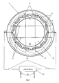
- FIGS. 1-4 Examples of magnetic systems of the electric machines described in Points 2-4 of the Claims section are shown, in static mode, in FIGS. 1-4 , respectively.
- FIG. 1 depicts an end view of the magnetic system of a DC electric motor, or DC power generator which consists of the magnetically soft core of the stator ( 1 ) with tangential, connected in series stator winding coils ( 2 ), their electrical terminals ( 3 ), and a control device ( 47 ) with terminals/wires ( 45 ), which, at each point in time connects an external two-wire grid ( 46 ), via electric contacts ( 4 ) and ( 5 ), with the specified, connected in series, tangential coils ( 2 ) of the stator winding.
- the control device selects new terminal/wires that connect the external two-wire grid with new contacts of the stator coil.
- force lines ( 6 ) and ( 7 ) of the magnetic field of the stator ( 1 ) and the rotor ( 8 ) penetrate the core of a two-pole rotor ( 8 ) and have an almost stable relative orientation during the rotation of the rotor ( 8 ) (approximately mutually perpendicular), which ensures a torque stability of the rotor ( 8 ) under a steady load.
- the rotor core may be a permanent magnet or an electromagnet; it may be a multi-pole (in particular, it may have two magnetic beveled poles) or may be designed with several squirrel-cage turns (a squirrel-cage rotor), or made of magnetically soft steel with two cut-off segments, or made of magnetically soft steel with permanent magnets inserted in bores thus making the core of the rotor ( 8 ) a whole a permanent magnet, etc.
- the rotor ( 8 ) is positioned relative to the stator ( 1 ) in such a manner as to enable a maximum momentum of the rotor ( 8 ) in the nominal state.
- the control device may disable them when generating the magnetic field. However, if these coils are dimensionally insignificant, this complication is not required.
- tangential coil Any coil ( 2 ) coiled around the core of the stator ( 1 ) with tangential arrangement of its axis shall hereinafter be referred to as tangential coil, or tangential stator winding coil.
- FIG. 2 shows an end view of the magnetic system of a DC electric motor, or DC electric generator, which consists of the magnetically soft core of the stator ( 9 ) with radial, connected in series stator winding coils ( 10 ), their electrical terminals—contacts ( 11 ), and a control device ( 44 ) with terminals/wires ( 42 ), which at any point in time connects an external two-wire grid ( 46 ) via electric contacts ( 12 ) and ( 13 ), with the specified, radial stator coils ( 10 ) connected in series. At subsequent times, the control device selects new terminal/wires that connect the external two-wire grid with new contacts of the stator coil.
- power lines ( 14 ) and ( 15 ) of the magnetic field of the stator ( 9 ) and the rotor ( 16 ) penetrate the core of a double-pole rotor ( 16 ) and have an almost stable relative orientation during the rotation of the rotor ( 16 ) (approximately mutually perpendicular), which ensures a torque stability of the rotor ( 16 ) under a steady load.
- the rotor core may be a permanent magnet or an electromagnet; it may be a multi-pole (in particular, it may have two magnetic beveled poles) or may be designed with several squirrel-cage turns (a squirrel-cage rotor) or made of magnetically soft steel with two cut-off segments, or made of magnetically soft steel with permanent magnets inserted in bores, thus making the core of the rotor ( 16 ) a whole a permanent magnet, etc.
- the rotor ( 16 ) is positioned relative to the stator ( 9 ) so that the rotor ( 16 ) has a maximum torque.
- stator winding coil ( 10 ) coiled around the core of the stator ( 9 ) with radial arrangement of its axis shall hereinafter be referred to as a radial coil or a radial stator winding coil.
- FIG. 3 shows an end view of the magnetic system of a DC power generator which consists of a rotor ( 17 ) with two beveled poles and a magnetically soft core of the stator ( 18 ) with tangential, connected in series to stator winding coils ( 19 ) and their electric terminals (contacts) ( 20 ) connected with the corresponding electric contacts ( 21 ) and ( 22 ) with terminals/wires ( 39 ) of a control device ( 41 ), which, in turn, at any point in time directs the induction electric current produced in the stator coils to the terminals of an external two-wire grid ( 40 ). At subsequent times, the control device selects new terminal/wires that connect the external two-wire grid with new contacts of the stator coil.
- the internal part of the rotor ( 23 ) is made of a nonmagnetic material. Lines ( 24 ) and ( 25 ) are magnetic lines of the stator ( 18 ) and the rotor ( 17 ), respectively.
- the two-pole rotor shown in FIG. 3 which consists of a hollow cylinder with two equal-sized magnets located in it and which has an oblique (beveled), for example, radial, magnetic field direction, shall hereinafter be referred to as a rotor with two beveled poles.
- the rotor ( 17 ) with nonmagnetic material in the cylinder cavity that contains the previously mentioned oblique (beveled) magnets shall be referred to as a rotor with two beveled poles.
- FIG. 4 shows an end view of the magnetic system of an AC power generator which consists of a two-pole rotor ( 26 ) and magnetically soft core of the stator ( 27 ) that has two equal-sized tangential stator coils ( 28 ) and ( 29 ) connected in series or back-to-back, whose two stationary electric terminals (contacts) ( 30 ) and ( 31 ) (or ( 32 ) and ( 33 )) are connected to the external two-wire grid ( 37 ) and are located, correspondingly, either on the opposite parts of the winding of the stator 27 (if the two stator winding coils ( 28 ) and ( 29 ) are connected in series), or next to each other (if the two stator winding coils ( 28 ) and ( 29 ) are connected back-to-back, in which case the dotted link between these two coils is absent).
- lines ( 34 ) of the magnetic field of the stator ( 27 ) do not rotate; lines ( 35 ) of the rotor rotate together with the rotor ( 26 ) and inductively generate alternating current in the coils ( 28 ) and ( 29 ) of the stator ( 27 ); the current is supplied to the external two-wire grid ( 37 ) via a control device ( 38 ) with terminals ( 36 ).
- the electric machine may have a reciprocating motion of the rotor and, accordingly, the stator magnetic field (not shown in figures).
- a two-pole magnet of the rotor
- chain control may arrange a corresponding motion of the stator magnetic field by controlling the electric current feed into the corresponding stator coils.
- Example 1 the DC electric machine shown in FIG. 1 can function as an electric motor and as a power generator (if rotor ( 8 ) is magnetized). If it is used as an electric motor, it needs to receive DC current from an external two-wire grid (through a control device). If the electric machine is used as a power generator, it will feed DC current to an external two-wire grid.
- electric contacts of coils ( 2 ) of the stator ( 1 ) are connected with the corresponding electric contacts ( 45 ) of the control device in order to generate a rotating magnetic field of the stator ( 1 ) depending on the position of the rotor ( 8 ).
- the rotation speed of the stator magnetic field may be maintained and changed arbitrarily, as required. In such cases, the rotation of the rotor ( 8 ), if not overloaded, will follow the rotation of the magnetic field of the stator ( 1 ). If the device is used as an electric motor, the coils of the stator ( 1 ) and rotor 8 may be powered simultaneously, either with a direct current or an alternating one.
- the DC electric machine shown in FIG. 2 can function either as an electric motor, or as a power generator. If it is used as an electric motor, it needs to receive DC current from an external two-wire grid (through a control device). If the electric machine is used as a power generator, it will feed DC current to an external two-wire grid.
- electric contacts ( 11 ) of the stator coils ( 10 ) are connected to the corresponding electric contacts ( 42 ) of the control device in order to generate a rotating magnetic field of the stator ( 9 ) depending on the position of the rotor ( 16 ).
- Example 3 the electric machine is a DC power generator.
- the rotor with two beveled poles ( 17 ) is rotated by an external force, a voltage appears at the electric contacts on the external two-wire grid ( 40 ); this voltage may be used to obtain direct current in this grid.
- a rotor with two beveled poles is used to reduce the energy consumption required for the rotor rotation, and therefore, to achieve a significant increase in efficiency of the DC power generator described herein.
- Example 4 the electric machine is an AC power generator.
- the rotor ( 26 ) is rotated by an external force, an alternating voltage appears at the two stationary electric terminals ( 30 ) and ( 31 ) (or ( 32 ) and ( 33 )) of the winding of the stator ( 27 ) connected to an external two-wire grid; this voltage may be used to obtain alternating current in this grid.
- This current arises as a result of electric current induced with a given direction in the two coils of the stator winding; the resulting utility is electric current in the external two-wire grid ( 37 ).
Landscapes
- Engineering & Computer Science (AREA)
- Power Engineering (AREA)
- Microelectronics & Electronic Packaging (AREA)
- Permanent Magnet Type Synchronous Machine (AREA)
- Windings For Motors And Generators (AREA)
- Synchronous Machinery (AREA)
- Control Of Eletrric Generators (AREA)
- Connection Of Motors, Electrical Generators, Mechanical Devices, And The Like (AREA)
- Iron Core Of Rotating Electric Machines (AREA)
Applications Claiming Priority (3)
| Application Number | Priority Date | Filing Date | Title |
|---|---|---|---|
| RU2014134464/07A RU2600311C2 (ru) | 2014-08-25 | 2014-08-25 | Электрическая машина |
| RU2014134464 | 2014-08-25 | ||
| PCT/RU2015/000404 WO2016032364A1 (ru) | 2014-08-25 | 2015-06-29 | Электрическая машина |
Publications (2)
| Publication Number | Publication Date |
|---|---|
| US20170214285A1 US20170214285A1 (en) | 2017-07-27 |
| US10476335B2 true US10476335B2 (en) | 2019-11-12 |
Family
ID=55400125
Family Applications (1)
| Application Number | Title | Priority Date | Filing Date |
|---|---|---|---|
| US15/328,745 Active 2036-03-09 US10476335B2 (en) | 2014-08-25 | 2015-06-29 | Electric machine |
Country Status (7)
| Country | Link |
|---|---|
| US (1) | US10476335B2 (zh) |
| EP (1) | EP3188346A4 (zh) |
| JP (1) | JP6584508B2 (zh) |
| CN (1) | CN107005115B (zh) |
| BR (1) | BR112017002864B1 (zh) |
| RU (1) | RU2600311C2 (zh) |
| WO (1) | WO2016032364A1 (zh) |
Families Citing this family (2)
| Publication number | Priority date | Publication date | Assignee | Title |
|---|---|---|---|---|
| US20190267852A1 (en) * | 2016-07-20 | 2019-08-29 | Dumitru Bojiuc | Variable magnetic monopole field electro-magnet and inductor |
| CN112003391B (zh) * | 2020-08-20 | 2021-07-20 | 珠海格力电器股份有限公司 | 定子铁芯、磁悬浮轴承、电机 |
Citations (6)
| Publication number | Priority date | Publication date | Assignee | Title |
|---|---|---|---|---|
| RU2030067C1 (ru) | 1988-01-26 | 1995-02-27 | Александр Иванович Краснопевцев | Шаговый электродвигатель |
| US6297575B1 (en) * | 1996-03-28 | 2001-10-02 | Tai-Her Yang | Combined power driven device having a three-layered electromechanical structure with common structures |
| US6455970B1 (en) | 1998-03-19 | 2002-09-24 | Bombardier Transportation Gmbh | Multi-phase transverse flux machine |
| RU2202849C2 (ru) | 2000-12-14 | 2003-04-20 | Томский политехнический университет | Скважинный электромашинный источник питания инклинометрической системы |
| RU2301488C1 (ru) | 2005-12-19 | 2007-06-20 | Владимир Александрович Соломин | Шаговый электродвигатель |
| US7602137B2 (en) * | 2006-02-20 | 2009-10-13 | Black & Decker Inc. | Electronically commutated motor and control system |
Family Cites Families (15)
| Publication number | Priority date | Publication date | Assignee | Title |
|---|---|---|---|---|
| GB1435941A (en) * | 1973-01-09 | 1976-05-19 | British Nuclear Fuels Ltd | Ac motors |
| JPS5430411A (en) * | 1977-08-10 | 1979-03-06 | Hitachi Ltd | Dc brushless motor |
| SU1327242A1 (ru) * | 1986-02-26 | 1987-07-30 | Ленинградское Инженерное Морское Училище Им.Адм.С.О.Макарова | Вентильный электродвигатель |
| US5200661A (en) * | 1989-12-15 | 1993-04-06 | Shramo Daniel J | Slotless, brushless, large air gap electric motor |
| JPH05116520A (ja) * | 1991-10-29 | 1993-05-14 | Mitsubishi Electric Corp | アクチユエータ |
| RU2089994C1 (ru) * | 1995-10-06 | 1997-09-10 | Альберт Владимирович Крашенинников | Бесконтактный компрессионный генератор |
| JP3414907B2 (ja) * | 1995-11-16 | 2003-06-09 | 松下電器産業株式会社 | モータ |
| JP3579272B2 (ja) * | 1998-12-10 | 2004-10-20 | ミネベア株式会社 | トロイダルコア型アクチュエータ |
| JP3445173B2 (ja) * | 1998-12-11 | 2003-09-08 | ミネベア株式会社 | バルブ付きアクチュエータ装置 |
| JP4172863B2 (ja) * | 1998-12-24 | 2008-10-29 | オリエンタルモーター株式会社 | 5相永久磁石型モータ |
| JP2007325355A (ja) * | 2006-05-30 | 2007-12-13 | Tadashi Umemori | モータ駆動システム |
| CN201307701Y (zh) * | 2006-02-20 | 2009-09-09 | 布莱克和戴克公司 | 电动工具 |
| JP5028949B2 (ja) * | 2006-10-20 | 2012-09-19 | 株式会社デンソー | 流体ポンプの制御装置 |
| JP2012090497A (ja) * | 2010-10-22 | 2012-05-10 | Jtekt Corp | ブラシレスモータ及び電動パワーステアリング装置 |
| UA63414U (uk) * | 2011-03-09 | 2011-10-10 | Виктор Федорович Чугунов | Тихохідний багатополюсний синхронний генератор |
-
2014
- 2014-08-25 RU RU2014134464/07A patent/RU2600311C2/ru active
-
2015
- 2015-06-29 JP JP2017531445A patent/JP6584508B2/ja active Active
- 2015-06-29 WO PCT/RU2015/000404 patent/WO2016032364A1/ru active Application Filing
- 2015-06-29 EP EP15837030.4A patent/EP3188346A4/en not_active Ceased
- 2015-06-29 US US15/328,745 patent/US10476335B2/en active Active
- 2015-06-29 CN CN201580045047.2A patent/CN107005115B/zh active Active
- 2015-06-29 BR BR112017002864-6A patent/BR112017002864B1/pt active IP Right Grant
Patent Citations (6)
| Publication number | Priority date | Publication date | Assignee | Title |
|---|---|---|---|---|
| RU2030067C1 (ru) | 1988-01-26 | 1995-02-27 | Александр Иванович Краснопевцев | Шаговый электродвигатель |
| US6297575B1 (en) * | 1996-03-28 | 2001-10-02 | Tai-Her Yang | Combined power driven device having a three-layered electromechanical structure with common structures |
| US6455970B1 (en) | 1998-03-19 | 2002-09-24 | Bombardier Transportation Gmbh | Multi-phase transverse flux machine |
| RU2202849C2 (ru) | 2000-12-14 | 2003-04-20 | Томский политехнический университет | Скважинный электромашинный источник питания инклинометрической системы |
| RU2301488C1 (ru) | 2005-12-19 | 2007-06-20 | Владимир Александрович Соломин | Шаговый электродвигатель |
| US7602137B2 (en) * | 2006-02-20 | 2009-10-13 | Black & Decker Inc. | Electronically commutated motor and control system |
Non-Patent Citations (2)
| Title |
|---|
| International Search Report-PCT/RU2015/000404-dated Nov. 5, 2015. |
| International Search Report—PCT/RU2015/000404—dated Nov. 5, 2015. |
Also Published As
| Publication number | Publication date |
|---|---|
| EP3188346A1 (en) | 2017-07-05 |
| US20170214285A1 (en) | 2017-07-27 |
| CN107005115A (zh) | 2017-08-01 |
| JP2017526334A (ja) | 2017-09-07 |
| JP6584508B2 (ja) | 2019-10-02 |
| RU2014134464A (ru) | 2016-03-20 |
| WO2016032364A1 (ru) | 2016-03-03 |
| CN107005115B (zh) | 2020-09-25 |
| RU2600311C2 (ru) | 2016-10-20 |
| BR112017002864A2 (pt) | 2018-01-30 |
| BR112017002864B1 (pt) | 2022-08-02 |
| EP3188346A4 (en) | 2018-04-25 |
Similar Documents
| Publication | Publication Date | Title |
|---|---|---|
| CN103441630B (zh) | 一种12/4极结构的三自由度磁悬浮开关磁阻电机 | |
| CN110829662B (zh) | 一种并列结构混合励磁无刷电机及其发电系统 | |
| CN102197574A (zh) | 包括同步电机和异步电机的混合机器 | |
| CN103337938A (zh) | 一种12/4极单绕组无轴承开关磁阻电机及其控制方法 | |
| CN104335464A (zh) | 同步电机 | |
| CN105932793A (zh) | 一种定子极不等间距双凸极永磁同步电机 | |
| CN106549547A (zh) | 一种混合磁钢磁通切换记忆电机 | |
| CN103560605B (zh) | 一种圆筒形两相开关磁阻震荡电机 | |
| US10476335B2 (en) | Electric machine | |
| CN110739891B (zh) | 一种电励磁同步磁阻无刷发电系统 | |
| CN203406811U (zh) | 具辅助激磁绕组的交叉互锁开关式直流环刷电机系统 | |
| CN105141104B (zh) | 一种轭部励磁绕组高功率密度混合励磁永磁直线发电机 | |
| CN204244045U (zh) | 带有反馈信号的新型高效同步电动机以及风扇 | |
| CN203491867U (zh) | 一种混合励磁双凸极永磁电动机 | |
| CN104767336A (zh) | 一种单相他励磁阻式发电机 | |
| CN108173403A (zh) | 一种变极扩速永磁同步电机 | |
| Spiessberger et al. | The four-pole planetary motor | |
| CN104079136A (zh) | 一种三相开关磁阻电机及正弦定子 | |
| CN103490685A (zh) | 具辅助激磁绕组的具导电环及电刷式开关式直流电机 | |
| CN210608875U (zh) | 一种径向磁场复合型磁通切换电机 | |
| Lu et al. | Influence of the armature current on suspension characteristics of a new bearingless doubly salient electro-magnetic motor | |
| KR101259171B1 (ko) | 고효율 전기모터, 고효율 전기 발전기 | |
| CN103219847B (zh) | 一种无刷无励磁机的谐波励磁的混合励磁永磁同步电机 | |
| Jia et al. | Design and analysis of a bearingless doubly salient permanent magnet machine | |
| SUZUKI et al. | A Study of High Torque Design in Small-size PM Vernier Motor |
Legal Events
| Date | Code | Title | Description |
|---|---|---|---|
| STPP | Information on status: patent application and granting procedure in general |
Free format text: NON FINAL ACTION MAILED |
|
| STPP | Information on status: patent application and granting procedure in general |
Free format text: RESPONSE TO NON-FINAL OFFICE ACTION ENTERED AND FORWARDED TO EXAMINER |
|
| STPP | Information on status: patent application and granting procedure in general |
Free format text: NOTICE OF ALLOWANCE MAILED -- APPLICATION RECEIVED IN OFFICE OF PUBLICATIONS |
|
| STPP | Information on status: patent application and granting procedure in general |
Free format text: PUBLICATIONS -- ISSUE FEE PAYMENT VERIFIED |
|
| STCF | Information on status: patent grant |
Free format text: PATENTED CASE |
|
| MAFP | Maintenance fee payment |
Free format text: PAYMENT OF MAINTENANCE FEE, 4TH YR, SMALL ENTITY (ORIGINAL EVENT CODE: M2551); ENTITY STATUS OF PATENT OWNER: SMALL ENTITY Year of fee payment: 4 |