US1040887A - Door stop and holder. - Google Patents
Door stop and holder. Download PDFInfo
- Publication number
- US1040887A US1040887A US1911661286A US1040887A US 1040887 A US1040887 A US 1040887A US 1911661286 A US1911661286 A US 1911661286A US 1040887 A US1040887 A US 1040887A
- Authority
- US
- United States
- Prior art keywords
- wedge
- holder
- door
- slot
- stop
- Prior art date
- Legal status (The legal status is an assumption and is not a legal conclusion. Google has not performed a legal analysis and makes no representation as to the accuracy of the status listed.)
- Expired - Lifetime
Links
- 238000005452 bending Methods 0.000 description 2
- 238000010276 construction Methods 0.000 description 2
- 239000002184 metal Substances 0.000 description 2
- 230000000881 depressing effect Effects 0.000 description 1
- 238000004519 manufacturing process Methods 0.000 description 1
- 239000000463 material Substances 0.000 description 1
- 230000000630 rising effect Effects 0.000 description 1
Images
Classifications
-
- E—FIXED CONSTRUCTIONS
- E05—LOCKS; KEYS; WINDOW OR DOOR FITTINGS; SAFES
- E05C—BOLTS OR FASTENING DEVICES FOR WINGS, SPECIALLY FOR DOORS OR WINDOWS
- E05C17/00—Devices for holding wings open; Devices for limiting opening of wings or for holding wings open by a movable member extending between frame and wing; Braking devices, stops or buffers, combined therewith
- E05C17/02—Devices for holding wings open; Devices for limiting opening of wings or for holding wings open by a movable member extending between frame and wing; Braking devices, stops or buffers, combined therewith by mechanical means
- E05C17/46—Devices for holding wings open; Devices for limiting opening of wings or for holding wings open by a movable member extending between frame and wing; Braking devices, stops or buffers, combined therewith by mechanical means in which the wing or a member fixed thereon is engaged by a movable fastening member in a fixed position; in which a movable fastening member mounted on the wing engages a stationary member
- E05C17/52—Devices for holding wings open; Devices for limiting opening of wings or for holding wings open by a movable member extending between frame and wing; Braking devices, stops or buffers, combined therewith by mechanical means in which the wing or a member fixed thereon is engaged by a movable fastening member in a fixed position; in which a movable fastening member mounted on the wing engages a stationary member comprising a snap, catch, or the like
-
- E—FIXED CONSTRUCTIONS
- E05—LOCKS; KEYS; WINDOW OR DOOR FITTINGS; SAFES
- E05C—BOLTS OR FASTENING DEVICES FOR WINGS, SPECIALLY FOR DOORS OR WINDOWS
- E05C19/00—Other devices specially designed for securing wings, e.g. with suction cups
- E05C19/06—Other devices specially designed for securing wings, e.g. with suction cups in which the securing part if formed or carried by a spring and moves only by distortion of the spring, e.g. snaps
- E05C19/063—Released by pull or pressure on the wing
-
- Y—GENERAL TAGGING OF NEW TECHNOLOGICAL DEVELOPMENTS; GENERAL TAGGING OF CROSS-SECTIONAL TECHNOLOGIES SPANNING OVER SEVERAL SECTIONS OF THE IPC; TECHNICAL SUBJECTS COVERED BY FORMER USPC CROSS-REFERENCE ART COLLECTIONS [XRACs] AND DIGESTS
- Y10—TECHNICAL SUBJECTS COVERED BY FORMER USPC
- Y10S—TECHNICAL SUBJECTS COVERED BY FORMER USPC CROSS-REFERENCE ART COLLECTIONS [XRACs] AND DIGESTS
- Y10S292/00—Closure fasteners
- Y10S292/19—Combined door holder and buffer
-
- Y—GENERAL TAGGING OF NEW TECHNOLOGICAL DEVELOPMENTS; GENERAL TAGGING OF CROSS-SECTIONAL TECHNOLOGIES SPANNING OVER SEVERAL SECTIONS OF THE IPC; TECHNICAL SUBJECTS COVERED BY FORMER USPC CROSS-REFERENCE ART COLLECTIONS [XRACs] AND DIGESTS
- Y10—TECHNICAL SUBJECTS COVERED BY FORMER USPC
- Y10T—TECHNICAL SUBJECTS COVERED BY FORMER US CLASSIFICATION
- Y10T292/00—Closure fasteners
- Y10T292/08—Bolts
- Y10T292/0876—Double acting
- Y10T292/088—Spring arm
Definitions
- UNITE 3il JACOB H. COFFMAN, OF PHILADELPHIA, PENNSYLVANIA.
- My invention relates to door stops and holders.
- a further object is to provide for moving the device from active into inoperative position without the necessity of bending over and adjusting it with the hand.
- the invention consists of a resilient compressible wedge adapted to gradually bring the door to a full stop, and a spring holder for retaining the door upon the stop.
- the wedge is preferably formed with a slot through which the spring holder projects, and said holder is usually made with a tongue which extends below the extremity of the slot in the wedge whereby the upward movement of the holder is limited and the parts are prevented from getting out of order.
- the outer end of the wedge carries a cushioned bumper, which is preferably formed in the specific manner hereinafter explained.
- the stop and holder are made of a single piece of metal which is pivotally secured to the floor near the base board, and the device may be easily turned back along the side of the base board, when not in use, or swung outwardly into operative position by the toe of the shoe without necessitating bending over and using the hand. 7
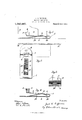
- Figure 1 is a side elevation of my door stop and holder, showing it in operation.
- Fig. 2 is a plan view of the device, its inoperative posi tion being indicated in dotted lines.
- Fig. 3 is a rear end view of the invention, and Fig.
- 1 designates the resilient compressible wedge comprising the bottom leaf or fold 2 and the inclined upper leaf or fold 3.
- the lower leaf projects beyond the upper one and is pivotally secured to the floor by a screw 4, or any other suitable means.
- the extremity of the upper leaf is bent upwardly forming a flange 5, carrying the cushioned bumper.
- Any suitable bumper will answer my purpose, but the one illustrated herein comprises a strip of rubber 6 bent into curved form and having its ends secured in vertical slots 7 formed in the flange 5.
- a device of the character described comprising a resilient compressible wedge, its upper leaf having a straight gradually rising upper surface extending to its free end, an upstanding flange on said free end of the upper leaf, said flange provided with two vertical slots, a strip of cushioning material bent into curved form and having its ends secured in said slots forming a stop, all for the purposes specified.
- a device of the character described comprising a resilient compressible wedge and spring holder made from a single piece of sheet metal, said wedge having a slot in its upper leaf, and the lower leaf of said wedge having the holder cut and struck up therefrom with an apex projecting through said slot at a point spaced well away from the upper end of said wedge.
Landscapes
- Engineering & Computer Science (AREA)
- Mechanical Engineering (AREA)
- Specific Sealing Or Ventilating Devices For Doors And Windows (AREA)
Description
J. H. COPPMAN.
DOOR STOP AND HOLDER.
APPLICATION FILED NOV. 20, 1911.
1,040,887. Patented Oct. 8, 1912.
witmeooeo awwntoz emmw tOLUMBlA PLANOGRAPH Tm-WASHINGTON. D. C.
UNITE 3il= JACOB H. COFFMAN, OF PHILADELPHIA, PENNSYLVANIA.
DOOR STOP AND HOLDER.
Specification of Letters Patent.
Patented Oct. 8,1912.
Application filed November 20, 1911. Serial No. 661,286.
To all whom it may concern:
Be it known that I, JACOB H. GOFFMAN, a citizen of the United States, residing at Philadelphia, in the county of Philadelphia and State of Pennsylvania, have invented certain new and useful Improvements in Door Stops and Holders; and I do hereby declare the following to be a full, clear, and exact description of the invention, such as will enable others skilled in the art to which it appertains to make and use the same.
My invention relates to door stops and holders.
It has for its object to provide a device of this character which will be simple in con struction, inexpensive to manufacture, neat in appearance, and eflicient in operation.
A further object is to provide for moving the device from active into inoperative position without the necessity of bending over and adjusting it with the hand.
Other objects will become apparent from the following description.
The invention consists of a resilient compressible wedge adapted to gradually bring the door to a full stop, and a spring holder for retaining the door upon the stop. The wedge is preferably formed with a slot through which the spring holder projects, and said holder is usually made with a tongue which extends below the extremity of the slot in the wedge whereby the upward movement of the holder is limited and the parts are prevented from getting out of order. The outer end of the wedge carries a cushioned bumper, which is preferably formed in the specific manner hereinafter explained. The stop and holder are made of a single piece of metal which is pivotally secured to the floor near the base board, and the device may be easily turned back along the side of the base board, when not in use, or swung outwardly into operative position by the toe of the shoe without necessitating bending over and using the hand. 7
The invention also consists in the features of construction and the combinations of parts hereinafter described, illustrated in the accompanying drawings and specified in the appended claims.
In the accompanying drawings ;Figure 1 is a side elevation of my door stop and holder, showing it in operation. Fig. 2 is a plan view of the device, its inoperative posi tion being indicated in dotted lines. Fig. 3 is a rear end view of the invention, and Fig.
4 is a central longitudinal, vertical sectional view thereof.
Referring more particularly to the drawing, 1 designates the resilient compressible wedge comprising the bottom leaf or fold 2 and the inclined upper leaf or fold 3. The lower leaf projects beyond the upper one and is pivotally secured to the floor by a screw 4, or any other suitable means. The extremity of the upper leaf is bent upwardly forming a flange 5, carrying the cushioned bumper. Any suitable bumper will answer my purpose, but the one illustrated herein comprises a strip of rubber 6 bent into curved form and having its ends secured in vertical slots 7 formed in the flange 5.
In the upper leaf of the wedge there is cut a central, longitudinal slot 8 into which extends the rounded apex 9 of the spring holder 10 which is cut and struck up from the lower leaf of said wedge. The extremity of the spring holder constitutes a tongue 11 which extends below the end of the slot 8 and serves to limit the upward movement of the holder.
In operation, when the device is turned outward to substantially right angles with the wall or base board A in Fig. 1, and the door B is swung open, its bottom edge rides up upon the wedge, depressing the upper leaf thereof to some extent until said door is brought to a stop by coming in contact with the bumper 6. In riding up the wedge, the bottom edge of the door also rides over the rounded apex 9 of the holder which engages the outer corner of the door and retains the latter upon the wedge. 'When it is desired to close the door a gentle push or pull upon the same will cause it to ride over the apex of the holder and off of the wed e. When the device is not in use it may e readily turned back along the side of the base board where it is entirely out of the way.
I claim 1. A device of the character described comprising a resilient compressible wedge, its upper leaf having a straight gradually rising upper surface extending to its free end, an upstanding flange on said free end of the upper leaf, said flange provided with two vertical slots, a strip of cushioning material bent into curved form and having its ends secured in said slots forming a stop, all for the purposes specified.
2. In a device of the character described, the combination with a resilient compressible wedge, of a spring holder inclined in the opposite direction from said wedge, and having an apex normally extending above said Wedge at a point spaced well away from the upper end of said wedge.
3. In a device of the character described, the combination, with a resilient compressible Wedge having a slot in its upper leaf, of a spring holder inclined in the opposite direction from said wedge and having an apex projecting through said slot at a point spaced well away from the upper end of said wedge.
4. In a device of the character described, the combination, with a resilient compressible wedge having a slot in its upper leaf, of a spring holder inclined in the opposite direction from said wedge and having an apex projecting through said slot at a point spaced well away from the upper end of said wedge, and a stop formed on the slotted upper leaf of said wedge at the upper end thereof.
5. A device of the character described, comprising a resilient compressible wedge and spring holder made from a single piece of sheet metal, said wedge having a slot in its upper leaf, and the lower leaf of said wedge having the holder cut and struck up therefrom with an apex projecting through said slot at a point spaced well away from the upper end of said wedge.
In testimony whereof, I affix my signature, in presence of two witnesses.
JACOB H. COFFMAN.
Witnesses:
HARRY N. CARTER, THOMAS H. ELLIS.
Copies of this patent may be obtained for five cents each, by addressing the Commissioner of Patents, Washington, D. C.
Priority Applications (1)
| Application Number | Priority Date | Filing Date | Title |
|---|---|---|---|
| US1911661286 US1040887A (en) | 1911-11-20 | 1911-11-20 | Door stop and holder. |
Applications Claiming Priority (1)
| Application Number | Priority Date | Filing Date | Title |
|---|---|---|---|
| US1911661286 US1040887A (en) | 1911-11-20 | 1911-11-20 | Door stop and holder. |
Publications (1)
| Publication Number | Publication Date |
|---|---|
| US1040887A true US1040887A (en) | 1912-10-08 |
Family
ID=3109160
Family Applications (1)
| Application Number | Title | Priority Date | Filing Date |
|---|---|---|---|
| US1911661286 Expired - Lifetime US1040887A (en) | 1911-11-20 | 1911-11-20 | Door stop and holder. |
Country Status (1)
| Country | Link |
|---|---|
| US (1) | US1040887A (en) |
Cited By (7)
| Publication number | Priority date | Publication date | Assignee | Title |
|---|---|---|---|---|
| US2784443A (en) * | 1953-05-25 | 1957-03-12 | Berg Wilfred Clement Von | Door retaining means |
| USD263558S (en) | 1979-11-16 | 1982-03-30 | Morita Mike Y | Combined door stop and latching device |
| US4653747A (en) * | 1985-06-28 | 1987-03-31 | Paul A. Newcomer, Inc. | Sit-up exercise apparatus |
| US20070266522A1 (en) * | 2006-05-16 | 2007-11-22 | Li Wayne W | Frictional door holder and stop |
| USD842946S1 (en) * | 2016-08-22 | 2019-03-12 | Fitness Anywhere LLC | Exercise apparatus wall anchor |
| US20250290330A1 (en) * | 2024-03-18 | 2025-09-18 | Plus Craft Industrial Co., Ltd. | Tile leveling structure |
| US20250290328A1 (en) * | 2024-03-18 | 2025-09-18 | Plus Craft Industrial Co., Ltd. | Tile leveling structure |
-
1911
- 1911-11-20 US US1911661286 patent/US1040887A/en not_active Expired - Lifetime
Cited By (7)
| Publication number | Priority date | Publication date | Assignee | Title |
|---|---|---|---|---|
| US2784443A (en) * | 1953-05-25 | 1957-03-12 | Berg Wilfred Clement Von | Door retaining means |
| USD263558S (en) | 1979-11-16 | 1982-03-30 | Morita Mike Y | Combined door stop and latching device |
| US4653747A (en) * | 1985-06-28 | 1987-03-31 | Paul A. Newcomer, Inc. | Sit-up exercise apparatus |
| US20070266522A1 (en) * | 2006-05-16 | 2007-11-22 | Li Wayne W | Frictional door holder and stop |
| USD842946S1 (en) * | 2016-08-22 | 2019-03-12 | Fitness Anywhere LLC | Exercise apparatus wall anchor |
| US20250290330A1 (en) * | 2024-03-18 | 2025-09-18 | Plus Craft Industrial Co., Ltd. | Tile leveling structure |
| US20250290328A1 (en) * | 2024-03-18 | 2025-09-18 | Plus Craft Industrial Co., Ltd. | Tile leveling structure |
Similar Documents
| Publication | Publication Date | Title |
|---|---|---|
| US1040887A (en) | Door stop and holder. | |
| US461375A (en) | Combined drawer guide and stop | |
| US1052525A (en) | Musical device. | |
| US936714A (en) | Closet-seat. | |
| US1122672A (en) | Paper-towel holder. | |
| US1115997A (en) | Shade-bracket. | |
| US1113618A (en) | Conical-sanitary-cup holder. | |
| US1229504A (en) | Thread cutter and holder. | |
| US441620A (en) | Elhanan l | |
| US816757A (en) | Door-holder. | |
| US701136A (en) | Door-holder. | |
| US1108894A (en) | Door-holder. | |
| US1559398A (en) | Bathroom fixture | |
| US886503A (en) | Combined door holder and bumper. | |
| US1237198A (en) | Toy. | |
| US801067A (en) | Bill-holder. | |
| US509305A (en) | Door-check | |
| US323027A (en) | William m | |
| US868083A (en) | Tablet and pencil holder. | |
| US478794A (en) | Implement-holder for tablets | |
| US861660A (en) | Combined hat and book holder. | |
| US1100583A (en) | Pen and pencil holder. | |
| US1087197A (en) | Ribbon device. | |
| US912326A (en) | Door-stop. | |
| US968059A (en) | Door-stop. |