US10396334B2 - Battery module and battery pack comprising same - Google Patents
Battery module and battery pack comprising same Download PDFInfo
- Publication number
- US10396334B2 US10396334B2 US15/128,778 US201515128778A US10396334B2 US 10396334 B2 US10396334 B2 US 10396334B2 US 201515128778 A US201515128778 A US 201515128778A US 10396334 B2 US10396334 B2 US 10396334B2
- Authority
- US
- United States
- Prior art keywords
- coupling unit
- electrode leads
- bus bar
- battery module
- plate
- Prior art date
- Legal status (The legal status is an assumption and is not a legal conclusion. Google has not performed a legal analysis and makes no representation as to the accuracy of the status listed.)
- Active, expires
Links
Images


Classifications
-
- H01M2/206—
-
- H—ELECTRICITY
- H01—ELECTRIC ELEMENTS
- H01M—PROCESSES OR MEANS, e.g. BATTERIES, FOR THE DIRECT CONVERSION OF CHEMICAL ENERGY INTO ELECTRICAL ENERGY
- H01M50/00—Constructional details or processes of manufacture of the non-active parts of electrochemical cells other than fuel cells, e.g. hybrid cells
- H01M50/50—Current conducting connections for cells or batteries
- H01M50/543—Terminals
- H01M50/547—Terminals characterised by the disposition of the terminals on the cells
- H01M50/548—Terminals characterised by the disposition of the terminals on the cells on opposite sides of the cell
-
- H—ELECTRICITY
- H01—ELECTRIC ELEMENTS
- H01M—PROCESSES OR MEANS, e.g. BATTERIES, FOR THE DIRECT CONVERSION OF CHEMICAL ENERGY INTO ELECTRICAL ENERGY
- H01M50/00—Constructional details or processes of manufacture of the non-active parts of electrochemical cells other than fuel cells, e.g. hybrid cells
- H01M50/20—Mountings; Secondary casings or frames; Racks, modules or packs; Suspension devices; Shock absorbers; Transport or carrying devices; Holders
-
- H01M2/024—
-
- H01M2/1061—
-
- H01M2/1077—
-
- H01M2/204—
-
- H01M2/26—
-
- H01M2/305—
-
- H—ELECTRICITY
- H01—ELECTRIC ELEMENTS
- H01M—PROCESSES OR MEANS, e.g. BATTERIES, FOR THE DIRECT CONVERSION OF CHEMICAL ENERGY INTO ELECTRICAL ENERGY
- H01M50/00—Constructional details or processes of manufacture of the non-active parts of electrochemical cells other than fuel cells, e.g. hybrid cells
- H01M50/10—Primary casings; Jackets or wrappings
- H01M50/102—Primary casings; Jackets or wrappings characterised by their shape or physical structure
- H01M50/105—Pouches or flexible bags
-
- H—ELECTRICITY
- H01—ELECTRIC ELEMENTS
- H01M—PROCESSES OR MEANS, e.g. BATTERIES, FOR THE DIRECT CONVERSION OF CHEMICAL ENERGY INTO ELECTRICAL ENERGY
- H01M50/00—Constructional details or processes of manufacture of the non-active parts of electrochemical cells other than fuel cells, e.g. hybrid cells
- H01M50/10—Primary casings; Jackets or wrappings
- H01M50/172—Arrangements of electric connectors penetrating the casing
- H01M50/174—Arrangements of electric connectors penetrating the casing adapted for the shape of the cells
- H01M50/178—Arrangements of electric connectors penetrating the casing adapted for the shape of the cells for pouch or flexible bag cells
-
- H—ELECTRICITY
- H01—ELECTRIC ELEMENTS
- H01M—PROCESSES OR MEANS, e.g. BATTERIES, FOR THE DIRECT CONVERSION OF CHEMICAL ENERGY INTO ELECTRICAL ENERGY
- H01M50/00—Constructional details or processes of manufacture of the non-active parts of electrochemical cells other than fuel cells, e.g. hybrid cells
- H01M50/20—Mountings; Secondary casings or frames; Racks, modules or packs; Suspension devices; Shock absorbers; Transport or carrying devices; Holders
- H01M50/204—Racks, modules or packs for multiple batteries or multiple cells
- H01M50/207—Racks, modules or packs for multiple batteries or multiple cells characterised by their shape
- H01M50/211—Racks, modules or packs for multiple batteries or multiple cells characterised by their shape adapted for pouch cells
-
- H—ELECTRICITY
- H01—ELECTRIC ELEMENTS
- H01M—PROCESSES OR MEANS, e.g. BATTERIES, FOR THE DIRECT CONVERSION OF CHEMICAL ENERGY INTO ELECTRICAL ENERGY
- H01M50/00—Constructional details or processes of manufacture of the non-active parts of electrochemical cells other than fuel cells, e.g. hybrid cells
- H01M50/50—Current conducting connections for cells or batteries
- H01M50/502—Interconnectors for connecting terminals of adjacent batteries; Interconnectors for connecting cells outside a battery casing
- H01M50/503—Interconnectors for connecting terminals of adjacent batteries; Interconnectors for connecting cells outside a battery casing characterised by the shape of the interconnectors
-
- H—ELECTRICITY
- H01—ELECTRIC ELEMENTS
- H01M—PROCESSES OR MEANS, e.g. BATTERIES, FOR THE DIRECT CONVERSION OF CHEMICAL ENERGY INTO ELECTRICAL ENERGY
- H01M50/00—Constructional details or processes of manufacture of the non-active parts of electrochemical cells other than fuel cells, e.g. hybrid cells
- H01M50/50—Current conducting connections for cells or batteries
- H01M50/502—Interconnectors for connecting terminals of adjacent batteries; Interconnectors for connecting cells outside a battery casing
- H01M50/507—Interconnectors for connecting terminals of adjacent batteries; Interconnectors for connecting cells outside a battery casing comprising an arrangement of two or more busbars within a container structure, e.g. busbar modules
-
- H—ELECTRICITY
- H01—ELECTRIC ELEMENTS
- H01M—PROCESSES OR MEANS, e.g. BATTERIES, FOR THE DIRECT CONVERSION OF CHEMICAL ENERGY INTO ELECTRICAL ENERGY
- H01M50/00—Constructional details or processes of manufacture of the non-active parts of electrochemical cells other than fuel cells, e.g. hybrid cells
- H01M50/50—Current conducting connections for cells or batteries
- H01M50/531—Electrode connections inside a battery casing
- H01M50/54—Connection of several leads or tabs of plate-like electrode stacks, e.g. electrode pole straps or bridges
-
- H—ELECTRICITY
- H01—ELECTRIC ELEMENTS
- H01M—PROCESSES OR MEANS, e.g. BATTERIES, FOR THE DIRECT CONVERSION OF CHEMICAL ENERGY INTO ELECTRICAL ENERGY
- H01M50/00—Constructional details or processes of manufacture of the non-active parts of electrochemical cells other than fuel cells, e.g. hybrid cells
- H01M50/50—Current conducting connections for cells or batteries
- H01M50/543—Terminals
- H01M50/552—Terminals characterised by their shape
- H01M50/553—Terminals adapted for prismatic, pouch or rectangular cells
-
- H—ELECTRICITY
- H01—ELECTRIC ELEMENTS
- H01M—PROCESSES OR MEANS, e.g. BATTERIES, FOR THE DIRECT CONVERSION OF CHEMICAL ENERGY INTO ELECTRICAL ENERGY
- H01M50/00—Constructional details or processes of manufacture of the non-active parts of electrochemical cells other than fuel cells, e.g. hybrid cells
- H01M50/50—Current conducting connections for cells or batteries
- H01M50/543—Terminals
- H01M50/564—Terminals characterised by their manufacturing process
- H01M50/566—Terminals characterised by their manufacturing process by welding, soldering or brazing
-
- B—PERFORMING OPERATIONS; TRANSPORTING
- B60—VEHICLES IN GENERAL
- B60L—PROPULSION OF ELECTRICALLY-PROPELLED VEHICLES; SUPPLYING ELECTRIC POWER FOR AUXILIARY EQUIPMENT OF ELECTRICALLY-PROPELLED VEHICLES; ELECTRODYNAMIC BRAKE SYSTEMS FOR VEHICLES IN GENERAL; MAGNETIC SUSPENSION OR LEVITATION FOR VEHICLES; MONITORING OPERATING VARIABLES OF ELECTRICALLY-PROPELLED VEHICLES; ELECTRIC SAFETY DEVICES FOR ELECTRICALLY-PROPELLED VEHICLES
- B60L50/00—Electric propulsion with power supplied within the vehicle
- B60L50/50—Electric propulsion with power supplied within the vehicle using propulsion power supplied by batteries or fuel cells
- B60L50/60—Electric propulsion with power supplied within the vehicle using propulsion power supplied by batteries or fuel cells using power supplied by batteries
- B60L50/64—Constructional details of batteries specially adapted for electric vehicles
-
- H—ELECTRICITY
- H01—ELECTRIC ELEMENTS
- H01M—PROCESSES OR MEANS, e.g. BATTERIES, FOR THE DIRECT CONVERSION OF CHEMICAL ENERGY INTO ELECTRICAL ENERGY
- H01M2220/00—Batteries for particular applications
- H01M2220/20—Batteries in motive systems, e.g. vehicle, ship, plane
-
- H—ELECTRICITY
- H01—ELECTRIC ELEMENTS
- H01M—PROCESSES OR MEANS, e.g. BATTERIES, FOR THE DIRECT CONVERSION OF CHEMICAL ENERGY INTO ELECTRICAL ENERGY
- H01M2220/00—Batteries for particular applications
- H01M2220/30—Batteries in portable systems, e.g. mobile phone, laptop
-
- Y—GENERAL TAGGING OF NEW TECHNOLOGICAL DEVELOPMENTS; GENERAL TAGGING OF CROSS-SECTIONAL TECHNOLOGIES SPANNING OVER SEVERAL SECTIONS OF THE IPC; TECHNICAL SUBJECTS COVERED BY FORMER USPC CROSS-REFERENCE ART COLLECTIONS [XRACs] AND DIGESTS
- Y02—TECHNOLOGIES OR APPLICATIONS FOR MITIGATION OR ADAPTATION AGAINST CLIMATE CHANGE
- Y02E—REDUCTION OF GREENHOUSE GAS [GHG] EMISSIONS, RELATED TO ENERGY GENERATION, TRANSMISSION OR DISTRIBUTION
- Y02E60/00—Enabling technologies; Technologies with a potential or indirect contribution to GHG emissions mitigation
- Y02E60/10—Energy storage using batteries
-
- Y—GENERAL TAGGING OF NEW TECHNOLOGICAL DEVELOPMENTS; GENERAL TAGGING OF CROSS-SECTIONAL TECHNOLOGIES SPANNING OVER SEVERAL SECTIONS OF THE IPC; TECHNICAL SUBJECTS COVERED BY FORMER USPC CROSS-REFERENCE ART COLLECTIONS [XRACs] AND DIGESTS
- Y02—TECHNOLOGIES OR APPLICATIONS FOR MITIGATION OR ADAPTATION AGAINST CLIMATE CHANGE
- Y02T—CLIMATE CHANGE MITIGATION TECHNOLOGIES RELATED TO TRANSPORTATION
- Y02T10/00—Road transport of goods or passengers
- Y02T10/60—Other road transportation technologies with climate change mitigation effect
- Y02T10/70—Energy storage systems for electromobility, e.g. batteries
Definitions
- the present disclosure relates to a battery module, and more particularly, to a battery module including three or more secondary batteries connected in parallel, to which a new coupling structure of an electrode lead and a bus bar is applied.
- lithium secondary batteries have little to no memory effect in comparison with nickel-based secondary batteries, and thus lithium secondary batteries are gaining a lot of attention for their advantages of free charging or discharging, low self-discharging, and high energy density.
- a lithium secondary battery generally uses lithium oxide and carbonaceous material as a positive electrode active material and negative electrode active material, respectively.
- the lithium secondary battery includes an electrode assembly in which a positive electrode plate and a negative electrode plate respectively coated with the positive electrode active material and the negative electrode active material are disposed with a separator being interposed between them, and an exterior, namely a case, which seals and accommodates the electrode assembly together with an electrolyte.
- a lithium secondary battery may be classified into a can-type secondary battery where the electrode assembly is included in a metal can and a pouch-type battery where the electrode assembly is included in a pouch of an aluminum laminate sheet, depending on the shape of the case.
- втори ⁇ ески ⁇ е кактро ⁇ ество are widely used not only for small-sized devices such as cellular phones but also middle-sized or large-sized devices such as vehicles and power storages.
- hybrid electric vehicles and electric vehicles attract attention globally, for example in US, Europe, Japan and Korea.
- a battery pack for giving a driving force to a vehicle motor is the most essential part. Since a hybrid electric vehicle or electric vehicle may obtain a driving force by means of charging and discharging of the battery pack, the hybrid electric vehicle or electric vehicle ensures excellent fuel efficiency and exhausts no or reduced pollutants, and for this reason, hybrid electric vehicles and electric vehicles are used more and more.
- the battery pack of the hybrid electric vehicle or electric vehicle includes a plurality of secondary batteries, and the plurality of secondary batteries are connected to each other in series or in parallel to improve capacity and output.
- Such parallel or series connection among secondary batteries may be determined in various ways depending on output, capacity, structure or the like of the battery pack in consideration of a device to which the battery pack is applied. Therefore, secondary batteries are connected in series or in parallel in various ways to configure a battery module, and the battery pack may include at least one battery module. In particular, the battery module may be configured so that three or more secondary batteries are connected in parallel, on occasions.
- electrode leads of the same polarity should be coupled to each other through a bus bar, and the electrode leads are frequently welded to stably maintain their coupled state.
- the electrode lead and the bus bar In order to weld the electrode lead and the bus bar, laser welding is representatively used.
- the welding reliability may not be ensured.
- the electrode leads are not welded agreeably to the bus bar, which may result in failure in welding.
- the welded portion may be separated while the battery module is manufactured or used later.
- the battery module may suffer from deteriorated performance or malfunction, and also the separated electrode lead may cause an electric short in the battery module, which may lead to fire or explosion.
- the ultrasonic welding may not ensure a sufficient welding strength in comparison to laser welding and may demand more costs due to exchange of consumables such as a horn and an anvil.
- the welding process becomes complicated, and the bus bars occupy a greater space in the battery module, which may increase costs.
- the present disclosure is designed to solve the problems of the related art, and therefore the present disclosure is directed to providing a battery module, in which laser welding can be used for coupling three or more electrode leads to a single bus bar, thereby enhancing adhesion and improving the ease of a manufacturing process, and is also directed to providing a battery pack including the battery module and a vehicle to which the battery module is applied.
- a battery module comprising: a plurality of secondary batteries, each including an electrode assembly, a case and an electrode lead; and a terminal bus bar having a plate-like coupling unit, wherein electrode leads of the same polarity provided in the three or more secondary batteries are coupled to the coupling unit, two or more electrode leads stacked to each other are in contact with one end of the coupling unit, and the other one or more electrode leads are in contact with the other end of the coupling unit.
- one electrode lead may be in contact with the other end of the coupling unit of the terminal bus bar.
- the electrode lead may be partially bent, and an end of the bent portion may be in contact with the terminal bus bar.
- the two or more electrode leads and the other one or more electrode leads may be respectively bent in opposite directions at both ends of the coupling unit and are in contact with the terminal bus bar.
- the two or more electrode leads and the other one or more electrode leads may be bent in a vertical direction.
- the two or more electrode leads and the other one or more electrode leads may be in contact with the same surface of the coupling unit of the terminal bus bar.
- the coupling unit of the terminal bus bar may be interposed between ends of the electrode leads and the case and be in contact with the electrode leads.
- the two or more electrode leads and the coupling unit of the terminal bus bar may be coupled to each other by means of laser welding, and the one or more electrode leads and the coupling unit of the terminal bus bar may be coupled to each other by means of laser welding.
- the battery module according to the present disclosure may further include an inter bus bar connected to the electrode leads of different polarities.
- the inter bus bar may include a plate-like first coupling unit, a plate-like second coupling unit and a connecting unit for connecting the first coupling unit and the second coupling unit, three or more electrode leads of different polarities may be coupled to the first coupling unit and the second coupling unit, two or more electrode leads stacked to each other may be in contact with one ends of the first coupling unit and the second coupling unit, and the other one or more electrode leads may be in contact with the other ends of the first coupling unit and the second coupling unit.
- the battery module may comprise two or more terminal bus bars.
- the battery module according to the present disclosure may further include a support member configured to support the two or more terminal bus bars.
- the battery module may comprise two or more support members respectively provided at opposite sides of the secondary battery.
- the terminal bus bar may further include a terminal part connected to an electrode terminal of the battery module and bent perpendicular to the coupling unit.
- the secondary battery may be a pouch-type secondary battery.
- the pouch-type secondary battery may include a positive electrode lead and a negative electrode lead which protrude in opposite directions.
- a battery pack which comprises the battery module according to the present disclosure.
- a vehicle which comprises the battery module according to the present disclosure.
- a welding strength between the bus bar and the electrode leads may be improved by decreasing the number of electrode leads overlapped on the bus bar.
- three or more electrode leads are coupled to a single bus bar in contact, and to the coupled portion, not only ultrasonic welding but also laser welding may be applied.
- the coupled portion may be fixed by means of laser welding.
- the laser welding ensures a greater welding strength in comparison to ultrasonic welding and does not require any cost for exchanging consumables such as a horn and an anvil, in this aspect of the present disclosure, it is possible to stably ensure a coupling force between the electrode leads and the bus bar and also lower the manufacture costs.
- FIG. 1 is an assembled perspective view schematically showing a battery module according to an embodiment of the present disclosure.
- FIG. 2 is an exploded perspective view of some components of FIG. 1 .
- FIG. 3 is an exploded perspective view schematically showing only a part of pouch-type secondary batteries stacked using stacking frames, in the configuration of FIGS. 1 and 2 .
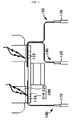
- FIG. 4 is a top view showing the configuration of FIG. 1 .
- FIG. 5 is an enlarged view showing a portion A of FIG. 4 .
- FIG. 6 is an enlarged view showing a portion B of FIG. 4 .
- FIG. 7 is an enlarged view showing portions C 1 and C 2 of FIG. 4 .
- FIG. 8 is an enlarged view showing a portion D of FIG. 4 .
- FIG. 1 is an assembled perspective view schematically showing a battery module according to an embodiment of the present disclosure
- FIG. 2 is an exploded perspective view of some components of FIG. 1 .
- the battery module according to the present disclosure includes a plurality of secondary batteries 100 and a terminal bus bar 200 .
- the secondary battery 100 includes an electrode assembly, a case 120 and an electrode lead 110 .
- the case 120 of the secondary battery 100 may contain an electrolyte therein.
- the electrode lead 110 may include a positive electrode lead and a negative electrode lead.
- the positive electrode lead may be connected to a positive electrode plate of an electrode assembly
- the negative electrode lead may be connected to a negative electrode plate of the electrode assembly.
- the secondary battery 100 may be a pouch-type secondary battery.
- the case 120 may be a pouch exterior.
- the pouch exterior may be configured so that a metal foil made of aluminum or the like is interposed between insulation layers. If the secondary battery 100 is a pouch-type secondary battery as described above, a plurality of secondary batteries 100 may be connected more easily.
- the battery module according to the present disclosure may further include a stacking frame 400 for stacking the pouch-type secondary batteries.
- FIG. 3 is an exploded perspective view schematically showing only a part of pouch-type secondary batteries 100 stacked using the stacking frame 400 , in the configuration of FIGS. 1 and 2 .
- FIG. 3 only four pouch-type secondary batteries 100 and two stacking frames 400 are depicted for convenience.
- the stacking frame 400 is a component used for stacking the pouch-type secondary batteries 100 , and the stacking frame 400 is configured to hold the secondary battery 100 and prevent the secondary battery 100 from moving.
- the stacking frames 400 are configured to be stacked to each other and thus guide the secondary batteries 100 to be assembled.
- the stacking frame 400 may also be called using various other terms such as cartridge and may have a rectangular ring shape with a hollow center. At this time, four edges of the stacking frame 400 may be located at the outer circumference of the secondary battery 100 . In addition, the secondary batteries 100 may be respectively located at both sides of the stacking frame 400 .
- the battery module according to the present disclosure may further include a cooling fin 410 .
- the cooling fin 410 may be made of thermally conductive material such as aluminum to exchange heat with the secondary battery 100 .
- the cooling fin 410 may be configured to be inserted into the center of the stacking frame 400 . Therefore, if the secondary batteries 100 are stacked using the stacking frame 400 , the cooling fin 410 may be interposed between the secondary batteries 100 . Meanwhile, the cooling fin 410 may be coupled to the stacking frame 400 by means of insert molding.
- two electrode leads 110 may be provided to protrude in opposite directions, as shown in FIGS. 1 to 3 .
- the pouch-type secondary battery 100 may be configured to have a rectangular shape with four sides, when being observed in a horizontal direction on the basis of FIG. 3 , and at this time, the positive electrode lead and the negative electrode lead may be provided to protrude at sides located opposite to each other.
- the positive electrode lead and the negative electrode lead may protrude forwards, and the other may protrude rearwards.
- each electrode lead 110 may have a sufficiently great size.
- the electrode lead 110 and the terminal bus bar 200 may contact through a greater area, and thus the electrode lead 110 and the terminal bus bar 200 may be coupled more easily.
- heat emission may be reduced.
- the present disclosure is not limited to the above embodiment, and the positive electrode lead and the negative electrode lead may also be located at the same side or at adjacent sides.
- the terminal bus bar 200 includes a plate-like coupling unit 210 , and the electrode lead 110 is coupled to a flat surface of the coupling unit 210 .
- the electrode lead 110 may be coupled to the coupling unit 210 of the terminal bus bar 200 .
- the coupling configuration of the coupling unit 210 of the terminal bus bar 200 and the electrode leads 110 will be described later in more detail with reference to FIGS. 4 and 5 .
- FIG. 4 is a top view showing the configuration of FIG. 1
- FIG. 5 is an enlarged view showing a portion A of FIG. 4 .
- each stacking frame 400 may accommodate two secondary batteries 100 .
- a coupling structure of the terminal bus bar 200 and the electrode lead 110 at a left top portion of the configuration of FIG. 4 is as shown in FIG. 5 .
- the terminal bus bar 200 is formed with a plate shape and includes a coupling unit 210 having broad surfaces at both sides thereof.
- the broad surfaces of the coupling unit 210 are disposed toward upper and lower directions.
- the electrode lead 110 provided at the secondary battery 100 has a plate shape with broad surfaces at both sides thereof, one of which may be coupled to the coupling unit 210 in contact while facing a broad surface of the coupling unit 210 .
- three electrode leads 110 may be coupled to the coupling unit 210 of a single terminal bus bar 200 .
- three electrode leads 110 are respectively provided at three secondary batteries 100 different from each other and may have the same polarity.
- three electrode leads 110 connected to a single terminal bus bar 200 as shown in FIG. 5 may be entirely positive electrode leads.
- three secondary batteries 100 may be connected to each other in parallel.
- two or more electrode leads 110 of three or more electrode lead 110 may be in contact with one end of the coupling unit 210 in a stacked state, and the other one or more electrode leads 110 may be in contact with the other end of the coupling unit 210 .
- the coupled portion of the electrode lead 110 and the terminal bus bar 200 may be fixed to each other by performing a welding process, as indicated by L in FIG. 5 .
- one or two electrode leads 110 are overlapped with respect to the coupling unit 210 of a single terminal bus bar 200 . Therefore, as indicated by L, laser welding may be performed to the contact portion of the electrode lead 110 and the terminal bus bar 200 to fix them to each other. In case of laser welding, three or more electrode leads 110 may not be easily welded to the bus bar in an overlapped state. However, in the configuration of the present disclosure, even though three or more electrode leads 110 are coupled to a single terminal bus bar 200 , the maximum number of electrode leads 110 overlapped with each other is just two, and thus they may be coupled by means of laser welding.
- laser welding when the electrode lead 110 and the terminal bus bar 200 are coupled, laser welding may be adopted.
- the laser welding may ensure excellent welding reliability since its welding strength is more excellent in comparison to other welding methods such as ultrasonic welding, and the costs for exchanging consumables such as a horn or an anvil used in ultrasonic welding may be reduced.
- laser welding may be used together with other welding methods such as ultrasonic welding, various welding methods may be used, which may increase the degree of freedom in designs and fabricating processes for a battery module and a battery pack.
- the electrode lead 110 is partially bent to form a bent portion, and an end of the bent portion may be in contact with the terminal bus bar 200 .
- three electrode leads 110 are respectively bent at portions indicated by C, and the ends of such bent portions may be coupled in contact with the coupling unit 210 of the terminal bus bar 200 .
- a plurality of electrode leads 110 in contact with the coupling unit 210 of the terminal bus bar 200 may be bent in opposite directions at both side ends of the coupling unit 210 and in contact with the terminal bus bar 200 .
- two left electrode leads 110 may be bent in a right direction to be in contact with a left end of the coupling unit 210 of the terminal bus bar 200
- one right electrode lead 110 may be bent in a left direction to be in contact with a right end of the coupling unit 210 of the terminal bus bar 200 .
- the plurality of electrode leads 110 may be bent vertically, and the bent ends are in contact with the coupling unit 210 of the terminal bus bar 200 .
- two left electrode leads 110 may be bent 90 degrees (°) in a right direction and in contact with the coupling unit 210 of the terminal bus bar 200
- one right electrode lead 110 may be bent 90 degrees in a left direction and in contact with the coupling unit 210 of the terminal bus bar 200 .
- the electrode leads 110 may be easily coupled to the coupling unit 210 of the terminal bus bar 200 , which has a shape of a flat plate.
- the electrode lead 110 when the electrode lead 110 is bent 90 degrees, the electrode lead 110 may be stably in contact with the flat surface of the coupling unit 210 of the terminal bus bar 200 , even though the electrode lead 110 is in contact with any of a left end and a right end of the coupling unit 210 of the terminal bus bar 200 .
- two electrode leads 110 are bent in an overlapped state and their bent ends are in contact with the left end of the coupling unit 210 of the terminal bus bar 200 , and one electrode lead 110 is bent solely and its bent end is in contact with the right end of the coupling unit 210 of the terminal bus bar 200 .
- the present disclosure is not limited to this embodiment.
- one electrode lead 110 is bent and its bent end is in contact with the left end of the coupling unit 210 of the terminal bus bar 200
- two electrode leads 110 are bent in an overlapped state and their bent ends are in contact with the right end of the coupling unit 210 of the terminal bus bar 200 .
- three or more electrode leads 110 coupled to a single terminal bus bar 200 may be in contact with the same surface of the coupling unit 210 of the terminal bus bar 200 .
- the coupling unit 210 of the terminal bus bar 200 may have a plate shape with broad surfaces at upper and lower portions thereof, and here, two left electrode leads 110 and one right electrode lead 110 may be entirely in contact with an outer surface or an inner surface of the coupling unit 210 of the terminal bus bar 200 .
- the outer surface means a surface of the coupling unit 210 of the terminal bus bar 200 , which is opposite to a side where the case 120 of the secondary battery 100 is located
- the inner surface means a surface at a side where the case 120 of the secondary battery 100 is located.
- all of two left electrode leads 110 and one right electrode lead 110 may be in contact with an upper surface, namely an outer surface, of the coupling unit 210 of the terminal bus bar 200 .
- the coupling unit 210 of the terminal bus bar 200 may be interposed between an end of the electrode lead 110 and the case 120 of the secondary battery 100 and in contact with the electrode lead 110 .
- the coupling unit 210 of the terminal bus bar 200 may be coupled in contact with the inner surface of the electrode lead 110 .
- the coupling unit 210 of the terminal bus bar 200 is not easily separated from the electrode lead 110 , but its coupling state to the electrode lead 110 may be more firmly maintained.
- the terminal bus bar 200 may be held not to move upwards.
- the terminal bus bar 200 since the terminal bus bar 200 is interposed between the bent end of the electrode lead 110 and the body of the secondary battery 100 , the terminal bus bar 200 located at a front side of the battery module may not be easily separated forwards.
- the terminal bus bar 200 may be prepared to be slid into the space between the bent end of the electrode lead 110 and the case 120 , in a lower direction as indicated by an arrow in FIG. 2 .
- the coupling unit 210 of the terminal bus bar 200 may have a protrusion protruding outwards at an outer surface thereof.
- the protrusion may be interposed between the bent ends of the electrode leads 110 coupled to outer surfaces of the corresponding terminal bus bar 200 .
- the protrusion may be provided to protrude forwards at a front surface, namely an outer surface, of the coupling unit 210 of the terminal bus bar 200 .
- one or two electrode leads 110 may be respectively in contact with a left end and a right end of the coupling unit 210 of the terminal bus bar 200 in a bent state.
- the protrusion formed at the coupling unit 210 of the terminal bus bar 200 may be located between the bent ends of such one or two electrode leads 110 .
- the protrusion of the terminal bus bar 200 may be located at a right side of the end of the electrode lead 110 bent at the left end of the terminal bus bar 200 and in contact therewith and a left side of the end of the electrode lead 110 bent at the right end of the terminal bus bar 200 and in contact therewith.
- the protrusion of the terminal bus bar 200 may serve as a guide when the terminal bus bar 200 and the electrode leads 110 are inserted. For example, if a bus bar is inserted between the bent ends of the electrode leads 110 and the case 120 of the secondary battery 100 as indicated by the arrow in FIG. 2 , the terminal bus bar 200 may be inserted in a state where the protrusion of the terminal bus bar 200 is located between the bent ends of the electrode leads 110 . Therefore, in this configuration of the present disclosure, when the terminal bus bar 200 is inserted or moved, the terminal bus bar 200 may be positioned more easily. Moreover, the protrusion may play a role of holding the terminal bus bar 200 not to move in a lateral direction in a state of being coupled to the electrode lead 110 , and thus the coupling force between the terminal bus bar 200 and the electrode lead 110 may be reinforced.
- terminal bus bars 200 may be provided.
- a terminal bus bar 200 coupled to three or more positive electrode leads and a terminal bus bar 200 coupled to three or more negative electrode leads may be separately included.
- FIG. 6 is an enlarged view showing a portion B of FIG. 4 .
- three electrode leads 110 are coupled to the coupling unit 210 of the terminal bus bar 200 .
- the battery module depicted in FIG. 4 includes twelve secondary batteries 100 in total, if three electrode leads 110 located at the portion A are positive electrode leads, three electrode leads 110 located at the portion B may be negative electrode leads.
- one left electrode lead 110 may be in contact with the left end of the terminal bus bar 200
- the other two right electrode leads 110 may be in contact with the right end of the coupling unit 210 of the terminal bus bar 200 .
- one left electrode lead 110 may be bent 90 degrees in a right direction and the bent end may be in contact with the left end of the coupling unit 210 of the terminal bus bar 200
- two right electrode leads 110 may be bent 90 degrees in a left direction and the bent end may be in contact with the right end of the coupling unit 210 of the terminal bus bar 200 .
- one electrode lead 110 in contact with the left end of the coupling unit 210 of the terminal bus bar 200 and two electrode leads 110 in contact with the right end of the coupling unit 210 of the terminal bus bar 200 may be in contact with the same surface of the coupling unit 210 of the terminal bus bar 200 , similar to the configuration of FIG. 5 .
- all of one left electrode lead 110 and two right electrode leads 110 may be in contact with the upper surface, namely the outer surface, of the coupling unit 210 of the terminal bus bar 200 , and in this case, the coupling unit 210 of the terminal bus bar 200 may be interposed between the end of the electrode lead 110 and the case 120 .
- the terminal bus bar 200 may further include a terminal part 220 .
- the terminal part 220 may be a portion of the terminal bus bar 200 , which is directly or indirectly connected to an electrode terminal of the battery module.
- the terminal part 220 may have a plate shape and be bent perpendicular to the coupling unit 210 to which the electrode leads 110 are coupled.
- the coupling unit 210 of the terminal bus bar 200 is configured to erect vertically, and the terminal part 220 may be configured to lie down in a front and rear direction, namely in a horizontal direction, to be perpendicular to the coupling unit 210 .
- the electrode terminal namely a positive electrode terminal or a negative electrode terminal
- the electrode terminal may be configured to have a bolt shape which erects vertically, and for easier coupling to such an electrode terminal, a concave groove may be formed at one side of the terminal part 220 so that the electrode terminal is inserted therein.
- a U-shaped groove may be formed at a front end of the terminal part 220 , and the electrode terminal may be inserted into the groove to be in contact with the terminal part 220 .
- the battery module according to the present disclosure may further include an inter bus bar 300 .
- the inter bus bar 300 may be connected to electrode leads 110 of different polarities, and particularly, all of three or more positive electrode leads and three or more negative electrode leads may be in contact with one inter bus bar 300 .
- a coupling configuration of the inter bus bar 300 and the electrode leads 110 will be described later in more detail with reference to FIGS. 7 and 8 .
- FIG. 7 is an enlarged view showing portions C 1 and C 2 of FIG. 4
- FIG. 8 is an enlarged view showing a portion D of FIG. 4 .
- the inter bus bar 300 may include a first coupling unit 310 , a second coupling unit 320 and a connecting unit 330 .
- the inter bus bar 300 may be coupled to six or more electrode leads 110 .
- the first coupling unit 310 and the second coupling unit 320 have a plate shape with a broad surface, and three or more electrode leads 110 may be respectively coupled thereto.
- three electrode leads 110 located at a left side may be coupled to the first coupling unit 310
- three electrode leads 110 located at a right side may be coupled to the second coupling unit 320 .
- the electrode leads 110 coupled to the first coupling unit 310 and the electrode leads 110 coupled to the second coupling unit 320 may have different polarities.
- three left secondary batteries 100 may be identical to three secondary batteries 100 depicted in FIG. 5 . Therefore, if three electrode leads 110 depicted in FIG. 5 are entirely positive electrode leads, three electrode leads 110 coupled to the first coupling unit 310 located at a left side of the inter bus bar 300 depicted in FIG. 7 may be entirely negative electrode leads. In addition, three electrode leads 110 coupled to the second coupling unit 320 located at a right side of the inter bus bar 300 of FIG. 7 may be entirely positive electrode leads.
- two electrode leads 110 in a stacked state are respectively in contact with one ends of the first coupling unit 310 and the second coupling unit 320 of the inter bus bar 300 , and one or two electrode leads 110 may be in contact with the other end thereof.
- FIGS. 7 and 8 depict the configuration where one electrode lead 110 is in contact with the other end of the inter bus bar 300 .
- two electrode leads 110 may be bent vertically at a right side in a stacked state to be in contact with a left end of the first coupling unit 310 , and the other one electrode lead 110 may be bent vertically at a left side to be in contact with a right end of the first coupling unit 310 .
- one electrode lead 110 may be bent vertically at a right side to be in contact with a left end of the second coupling unit 320
- the other two electrode leads 110 may be bent vertically at a left side in a stacked state to be in contact with a right end of the second coupling unit 320 .
- the connecting unit 330 connects the first coupling unit 310 and the second coupling unit 320 to each other. Therefore, the electrode lead 110 coupled to the first coupling unit 310 and the electrode lead 110 coupled to the second coupling unit 320 may be electrically connected to each other. Therefore, among six secondary batteries 100 depicted in FIG. 7 , if negative electrode leads of three left secondary batteries 100 are coupled to the first coupling unit 310 and positive electrode leads of the other three right secondary battery 100 are coupled to the second coupling unit 320 , three left secondary batteries 100 may be connected to each other in parallel and three right secondary batteries 100 may be connected to each other in parallel, respectively, and also three left secondary batteries 100 and three right secondary batteries 100 respectively connected in parallel may be connected to each other in series.
- three left electrode leads 110 may be coupled to the first coupling unit 310 of the inter bus bar 300 depicted in FIG. 8 .
- one electrode lead 110 located at a leftmost side may be bent in a right direction and be in contact with a left end of the first coupling unit 310
- the other two electrode leads 110 may be bent in a left direction in an overlapped state and be in contact with a right end of the first coupling unit 310 .
- three right electrode leads 110 may be positive electrode leads.
- three right electrode leads 110 may be coupled to the second coupling unit 320 of the inter bus bar 300 depicted in FIG. 8 .
- two left electrode leads 110 may be bent in a right direction in a stacked state and be in contact with a left end of the second coupling unit 320
- the other one right electrode lead 110 may be bent in a left direction and be in contact with a right end of the second coupling unit 320 .
- the first coupling unit 310 and the second coupling unit 320 may also be connected to each other by means of the connecting unit 330 . Therefore, in the configuration of FIG. 8 , three left secondary batteries 100 may be connected to each other in parallel, three right secondary batteries 100 may be connected to each other in parallel, and three left secondary batteries 100 and three right secondary batteries 100 respectively connected in parallel may be connected to each other in series to configure 3-parallel 2-series (3P-2S) connection.
- FIG. 7 may also be applied to the portion C 2 of FIG. 4 .
- three left secondary batteries 100 of FIG. 7 may be identical to three right secondary batteries 100 of FIG. 8 . Therefore, if three right electrode leads 110 depicted in FIG. 8 are positive electrode leads, three left electrode leads 110 depicted in FIG. 7 may be negative electrode leads.
- two negative electrode leads may be bent in a right direction in a stacked state and be in contact with the left end of the first coupling unit 310 , and the other one negative electrode lead may be bent in a left direction and be in contact with the right end of the first coupling unit 310 .
- three right electrode leads 110 depicted in FIG. 7 may be positive electrode leads, and among them, one positive electrode lead may be bent in a right direction and be in contact with the left end of the second coupling unit 320 , and the other two positive electrode leads may be bent in a left direction in a stacked state and be in contact with the right end of the second coupling unit 320 .
- the battery module according to the present disclosure may further include a support member 500 .
- the support member 500 may support two or more terminal bus bars 200 .
- the support member 500 may support the inter bus bars 300 .
- the terminal bus bar 200 and/or the inter bus bar 300 may be at least partially coupled and fixed to the support member 500 .
- the terminal bus bar 200 and the inter bus bar 300 may be coupled to the electrode lead 110 of the secondary battery 100 more easily.
- a single secondary battery 100 may include at least two electrode leads 110 including a positive electrode lead and a negative electrode lead
- at least two support members 500 may be included in the battery module.
- the electrode leads 110 of the secondary batteries 100 protrude in opposite directions, two support members 500 may be provided at a side opposite to the secondary batteries 100 .
- the positive electrode lead and the negative electrode lead of each secondary battery 100 may be provided at a front end and a rear end respectively as shown in FIG. 2 , and in this case one support member 500 may be located at the front end of the secondary battery 100 , and the other one support member 500 may be located at the rear end of the secondary battery 100 .
- the electrode leads 110 of the secondary battery 100 may be located at the same side.
- some terminal bus bars 200 and inter bus bars 300 may be inserted downwards, and the other terminal bus bars 200 and the other inter bus bars 300 may be inserted upwards.
- two support members 500 supporting the terminal bus bars 200 or the inter bus bars 300 are included in the battery module, two support members 500 may be located at a front end of the secondary battery 100 including the electrode leads 110 .
- one support member 500 may move downwards so that an outer surface of the terminal bus bar 200 or the inter bus bar 300 supported by one support member 500 is in contact with the electrode lead 110
- the other one support member 500 may move upwards so that an outer surface of the terminal bus bar 200 or the inter bus bar 300 supported by the other one support member 500 is in contact with the electrode lead 110 .
- three electrode leads 110 may also be in contact with different surfaces of the coupling unit 210 .
- one left electrode lead 110 and one right electrode lead 110 may be in contact with the outer surface, namely the upper surface, of the coupling unit 210
- one middle electrode lead 110 may be in contact with the inner surface, namely the lower surface, of the coupling unit 210 .
- the outward movement of the coupling unit 210 may be restricted by one left electrode lead 110 and one right electrode lead 110 , and the inward movement of the coupling unit 210 may be restricted by one middle electrode lead 110 . Therefore, in this configuration of the present disclosure, it is possible to prevent the terminal bus bar 200 or the inter bus bar 300 from moving inwards or outwards.
- the battery module according to the present disclosure may include a connector 600 .
- the connector 600 may serve as a terminal which is connected to a control device included in a battery pack, for example a battery management system (BMS).
- BMS battery management system
- the connector 600 may be provided at the support member 500 which supports the terminal bus bar 200 and the inter bus bar 300 .
- the battery pack according to the present disclosure includes at least one battery module as described above.
- the battery pack may further include a case 120 for covering the battery module, and various devices for controlling charging/discharging of the battery module, for example BMS, a current sensor, a fuse or the like.
- the battery module according to the present disclosure may be applied to a vehicle such as an electric vehicle and a hybrid vehicle.
- the vehicle according to the present disclosure may include the battery module according to the present disclosure.
Landscapes
- Chemical & Material Sciences (AREA)
- Chemical Kinetics & Catalysis (AREA)
- Electrochemistry (AREA)
- General Chemical & Material Sciences (AREA)
- Engineering & Computer Science (AREA)
- Manufacturing & Machinery (AREA)
- Life Sciences & Earth Sciences (AREA)
- Sustainable Development (AREA)
- Sustainable Energy (AREA)
- Power Engineering (AREA)
- Transportation (AREA)
- Mechanical Engineering (AREA)
- Connection Of Batteries Or Terminals (AREA)
- Battery Mounting, Suspending (AREA)
Applications Claiming Priority (5)
| Application Number | Priority Date | Filing Date | Title |
|---|---|---|---|
| KR20140037969 | 2014-03-31 | ||
| KR10-2014-0037969 | 2014-03-31 | ||
| KR10-2015-0031449 | 2015-03-06 | ||
| KR1020150031449A KR101821378B1 (ko) | 2014-03-31 | 2015-03-06 | 전극 리드와 버스바 사이의 결합력 및 공정성이 향상된 배터리 모듈 및 이를 포함하는 배터리 팩 |
| PCT/KR2015/002212 WO2015152527A1 (ko) | 2014-03-31 | 2015-03-06 | 배터리 모듈 및 이를 포함하는 배터리 팩 |
Publications (2)
| Publication Number | Publication Date |
|---|---|
| US20170125774A1 US20170125774A1 (en) | 2017-05-04 |
| US10396334B2 true US10396334B2 (en) | 2019-08-27 |
Family
ID=54346670
Family Applications (1)
| Application Number | Title | Priority Date | Filing Date |
|---|---|---|---|
| US15/128,778 Active 2035-10-20 US10396334B2 (en) | 2014-03-31 | 2015-03-06 | Battery module and battery pack comprising same |
Country Status (5)
| Country | Link |
|---|---|
| US (1) | US10396334B2 (pl) |
| EP (1) | EP3109925B1 (pl) |
| KR (1) | KR101821378B1 (pl) |
| CN (1) | CN106133948B (pl) |
| PL (1) | PL3109925T3 (pl) |
Cited By (1)
| Publication number | Priority date | Publication date | Assignee | Title |
|---|---|---|---|---|
| US12206134B2 (en) | 2018-09-05 | 2025-01-21 | Hesse Gmbh | Method for electrically contacting a battery block |
Families Citing this family (72)
| Publication number | Priority date | Publication date | Assignee | Title |
|---|---|---|---|---|
| JP6876964B2 (ja) * | 2015-09-30 | 2021-05-26 | パナソニックIpマネジメント株式会社 | 電池モジュール |
| KR102063935B1 (ko) * | 2015-10-13 | 2020-01-08 | 주식회사 엘지화학 | 배터리 모듈 |
| KR102062316B1 (ko) * | 2015-10-15 | 2020-01-03 | 주식회사 엘지화학 | 배터리 모듈 및 이를 포함하는 배터리 팩 |
| KR102016716B1 (ko) * | 2015-10-30 | 2019-09-02 | 주식회사 엘지화학 | 전지 팩 |
| KR102032503B1 (ko) * | 2015-11-05 | 2019-10-15 | 주식회사 엘지화학 | 배터리 모듈, 이러한 배터리 모듈을 포함하는 배터리 팩 및 이러한 배터리 팩을 포함하는 자동차 |
| KR102056875B1 (ko) | 2015-11-10 | 2019-12-17 | 주식회사 엘지화학 | 배터리 모듈 및 이를 포함하는 배터리 팩 |
| KR102082386B1 (ko) * | 2016-01-12 | 2020-02-27 | 주식회사 엘지화학 | Z축 방향 하중을 분산하는 구조의 전지모듈 |
| KR102101429B1 (ko) | 2016-05-18 | 2020-04-16 | 주식회사 엘지화학 | 리드 용접 장치, 이러한 리드 용접 장치를 통해 제조되는 배터리 모듈 및 이러한 배터리 모듈을 포함하는 배터리 팩 |
| KR102569937B1 (ko) * | 2016-07-27 | 2023-08-22 | 주식회사 엘지에너지솔루션 | 전극 리드 연결용 커넥터 및 이를 이용한 배터리 모듈 |
| DE102016114081A1 (de) * | 2016-07-29 | 2018-02-01 | Proton Motor Fuel Cell Gmbh | Brennstoffzellensystem und Verfahren zum Betrieb eines Brennstoffzellensystems |
| US11367916B2 (en) * | 2016-09-23 | 2022-06-21 | Artisan Vehicle Systems, Inc. | Modular battery cover for electric vehicle |
| KR102102927B1 (ko) * | 2016-10-06 | 2020-04-21 | 주식회사 엘지화학 | 배터리 모듈, 이러한 배터리 모듈을 포함하는 배터리 팩 및 이러한 배터리 팩을 포함하는 자동차 |
| DE102016118977B4 (de) * | 2016-10-06 | 2022-01-20 | Clarios Advanced Solutions Gmbh | Energiespeichermodul und Verfahren zum Zusammenbau |
| KR101912015B1 (ko) | 2016-11-15 | 2018-10-25 | 엘지전자 주식회사 | 배터리 팩 |
| KR102017781B1 (ko) | 2016-11-29 | 2019-09-03 | 주식회사 엘지화학 | 셀 리드의 고정구조가 개선된 배터리 팩 |
| US11088410B2 (en) * | 2016-12-23 | 2021-08-10 | Sk Innovation Co., Ltd. | Battery module |
| KR102766756B1 (ko) * | 2017-04-20 | 2025-02-14 | 에이일이삼 시스템즈 엘엘씨 | 배터리 탭 구성 |
| KR102082498B1 (ko) | 2017-04-26 | 2020-02-27 | 주식회사 엘지화학 | 전극 리드와 버스바의 결합 구조가 개선된 배터리 모듈 및 그 제조 방법 |
| KR102157377B1 (ko) | 2017-05-25 | 2020-09-17 | 주식회사 엘지화학 | 배터리 모듈, 이를 포함하는 배터리 팩 및 배터리 모듈 생산 방법 |
| KR102201344B1 (ko) | 2017-05-26 | 2021-01-08 | 주식회사 엘지화학 | 배터리 모듈과 이를 포함하는 배터리 팩 및 자동차 |
| KR102209773B1 (ko) | 2017-05-29 | 2021-01-28 | 주식회사 엘지화학 | 배터리 모듈 |
| WO2018220197A2 (de) * | 2017-06-01 | 2018-12-06 | Johnson Controls Advanced Power Solutions Gmbh | Elektrochemische zellbaugruppe, energiespeichermodul und verfahren zum zusammenbau davon |
| KR102152347B1 (ko) | 2017-06-22 | 2020-09-04 | 주식회사 엘지화학 | 배터리 팩 |
| WO2019013591A1 (ko) * | 2017-07-14 | 2019-01-17 | 주식회사 엘지화학 | 배터리 모듈 |
| KR102144945B1 (ko) | 2017-07-14 | 2020-08-14 | 주식회사 엘지화학 | 배터리 모듈 |
| KR102169632B1 (ko) | 2017-07-28 | 2020-10-23 | 주식회사 엘지화학 | 배터리 모듈, 이를 포함하는 배터리 팩 및 전력 저장 장치 |
| KR102187067B1 (ko) * | 2017-08-10 | 2020-12-04 | 주식회사 엘지화학 | 배터리 모듈 및 배터리 모듈의 제조 방법 |
| CN107732059B (zh) * | 2017-09-07 | 2023-08-29 | 江苏新晟新能源科技有限公司 | 一种方形锂电池标准化模组封装壳体及pack方法 |
| KR102155888B1 (ko) * | 2017-09-11 | 2020-09-14 | 주식회사 엘지화학 | 레이저 용접 지그 및 이를 포함하는 레이저 용접 장치 |
| KR102177694B1 (ko) * | 2017-11-06 | 2020-11-11 | 주식회사 엘지화학 | 버스바 어셈블리를 포함하는 배터리 모듈 |
| KR102258819B1 (ko) | 2017-11-24 | 2021-05-31 | 주식회사 엘지에너지솔루션 | 전기적 연결 안전성이 향상된 배터리 모듈 |
| KR102270266B1 (ko) * | 2017-11-30 | 2021-06-28 | 주식회사 엘지에너지솔루션 | 버스바 어셈블리를 구비한 배터리 모듈 |
| KR102364283B1 (ko) * | 2017-12-01 | 2022-02-16 | 주식회사 엘지에너지솔루션 | 방열 플레이트를 구비한 배터리 모듈 |
| KR102106446B1 (ko) * | 2017-12-08 | 2020-05-04 | 삼성에스디아이 주식회사 | 배터리 모듈 |
| KR102270828B1 (ko) | 2017-12-19 | 2021-06-29 | 주식회사 엘지에너지솔루션 | 버스바 어셈블리를 구비한 배터리 모듈 |
| KR102519443B1 (ko) * | 2017-12-27 | 2023-04-07 | 삼성에스디아이 주식회사 | 배터리 팩 |
| KR102328124B1 (ko) * | 2018-01-26 | 2021-11-17 | 주식회사 엘지에너지솔루션 | 전지 모듈 및 전지 모듈 어셈블리 |
| KR102598811B1 (ko) * | 2018-03-06 | 2023-11-03 | 에스케이온 주식회사 | 배터리 모듈 및 이의 제조방법 |
| KR102484424B1 (ko) | 2018-03-26 | 2023-01-04 | 에이치그린파워 주식회사 | 버스바 내장 카트리지 |
| KR102340898B1 (ko) * | 2018-03-30 | 2021-12-16 | 주식회사 엘지에너지솔루션 | 조립성이 향상된 버스바 프레임을 구비한 배터리 모듈 |
| KR102246385B1 (ko) * | 2018-06-19 | 2021-05-03 | (주) 코스텍 | 부스바의 제조장치 및 제조방법 |
| KR102523098B1 (ko) * | 2018-06-22 | 2023-04-17 | 주식회사 엘지에너지솔루션 | 이차 전지 및 이를 포함한 배터리 모듈 |
| KR102393936B1 (ko) * | 2018-09-10 | 2022-05-03 | 주식회사 엘지에너지솔루션 | Icb 조립체, 이를 포함한 배터리 모듈 및 그 제조 방법 |
| KR102404239B1 (ko) * | 2018-09-10 | 2022-05-30 | 주식회사 엘지에너지솔루션 | Icb 조립체, 이를 포함한 배터리 모듈 및 그 제조 방법 |
| EP3767706B1 (en) * | 2018-10-26 | 2023-09-27 | LG Energy Solution, Ltd. | Battery module having structure capable of preventing battery cell damage, and battery pack and vehicle comprising battery module |
| KR102443098B1 (ko) * | 2018-11-12 | 2022-09-13 | 주식회사 엘지에너지솔루션 | 모듈 하우징을 포함한 배터리 모듈 |
| CN111200110A (zh) | 2018-11-16 | 2020-05-26 | 宁德时代新能源科技股份有限公司 | 一种正极极片及电化学装置 |
| CN111200114B (zh) * | 2018-11-16 | 2021-06-08 | 宁德时代新能源科技股份有限公司 | 一种正极极片及电化学装置 |
| CN111200095B (zh) * | 2018-11-19 | 2024-10-18 | 宁德时代新能源科技股份有限公司 | 电池模组 |
| KR102714945B1 (ko) * | 2018-11-28 | 2024-10-07 | 주식회사 엘지에너지솔루션 | 배터리 모듈 및 그 제조방법 |
| KR102532768B1 (ko) | 2018-11-30 | 2023-05-12 | 주식회사 엘지에너지솔루션 | 안전성이 개선된 배터리 모듈, 이러한 배터리 모듈을 포함하는 배터리 팩 및 이러한 배터리 팩을 포함하는 자동차 |
| DE102018132179A1 (de) | 2018-12-13 | 2020-06-18 | Bayerische Motoren Werke Aktiengesellschaft | Energiespeicherzelle, Herstellungsverfahren und Vorrichtung zum Ausführen eines Solchen |
| KR102367381B1 (ko) | 2018-12-26 | 2022-02-23 | 주식회사 엘지에너지솔루션 | 이물질 유입 방지 구조를 갖는 배터리 모듈, 이를 포함하는 배터리 팩 및 자동차 |
| CN111490216B (zh) * | 2019-01-28 | 2024-11-29 | 宁德时代新能源科技股份有限公司 | 电池模组 |
| CN111668434B (zh) * | 2019-03-08 | 2022-03-15 | 比亚迪股份有限公司 | 电池模组和具有其的车辆 |
| KR102779614B1 (ko) * | 2019-03-12 | 2025-03-10 | 주식회사 엘지에너지솔루션 | 전지 모듈 및 그 제조 방법 |
| DE102019001893A1 (de) | 2019-03-18 | 2019-11-14 | Daimler Ag | Verfahren zur Herstellung von elektrischen Verbindungen wenigstens zweier Batteriezellen für eine Batterie eines Kraftfahrzeugs, insbesondere eines Kraftwagens |
| EP4358654A3 (en) | 2019-03-28 | 2024-12-04 | CPS Technology Holdings LLC | Flexible circuit having a fuse, bus bar holder including a lead-in structure, electrical conduction assembly having a bus bar, and battery including the same |
| KR20200141918A (ko) * | 2019-06-11 | 2020-12-21 | 주식회사 엘지화학 | 안전성 개선용 터미널 버스바, 이를 포함하는 배터리 모듈 및 배터리 팩 |
| CN110233519A (zh) * | 2019-06-22 | 2019-09-13 | 广东亿鼎新能源汽车有限公司 | 便捷储能发电系统 |
| KR102808865B1 (ko) * | 2019-07-23 | 2025-05-19 | 에스케이온 주식회사 | 배터리 모듈 |
| US11437666B2 (en) * | 2019-07-31 | 2022-09-06 | Karma Automotive Llc | Battery module including side pressure plates and pouch cell modules |
| KR102453307B1 (ko) | 2019-10-10 | 2022-10-07 | 주식회사 엘지에너지솔루션 | 전지 모듈 및 이를 포함하는 전지 팩 |
| KR102833705B1 (ko) * | 2019-10-23 | 2025-07-14 | 주식회사 엘지에너지솔루션 | 이차전지 탭 레이저 용접을 위한 밀착 지그 및 용접 방법 |
| KR102814166B1 (ko) * | 2019-12-05 | 2025-05-28 | 주식회사 엘지에너지솔루션 | 열 확산 방지 부재를 포함하는 전지 팩 |
| IT202000006016A1 (it) * | 2020-03-20 | 2021-09-20 | Comau Spa | "Apparecchiatura per assemblare celle di batteria o moduli di batteria" |
| CN111477800A (zh) * | 2020-04-30 | 2020-07-31 | 昆山宝创新能源科技有限公司 | 电池模块、电池包和车辆 |
| CN111477828A (zh) * | 2020-04-30 | 2020-07-31 | 昆山宝创新能源科技有限公司 | 电池模块及具有其的电池模组和汽车 |
| KR102495960B1 (ko) | 2020-08-14 | 2023-02-06 | 신성에스티 주식회사 | 전기차 배터리모듈용 버스바의 제조방법 |
| KR102866485B1 (ko) * | 2021-06-09 | 2025-09-29 | 주식회사 엘지에너지솔루션 | 절곡된 형태의 센싱 유닛을 포함하는 전지모듈 및 이를 포함하는 전자기기 |
| KR20230111039A (ko) * | 2022-01-17 | 2023-07-25 | 현대모비스 주식회사 | 배터리 모듈 및 그 배터리 모듈의 제조 방법 |
| KR102915631B1 (ko) * | 2022-11-17 | 2026-01-21 | 주식회사 엘지에너지솔루션 | 상하단 분리형 버스바프레임을 포함하는 배터리 모듈 및 이를 조립하는 방법 |
Citations (11)
| Publication number | Priority date | Publication date | Assignee | Title |
|---|---|---|---|---|
| JP2004087337A (ja) | 2002-08-27 | 2004-03-18 | Nissan Motor Co Ltd | 電池積層集合体およびそれに用いる電池 |
| KR20090017988A (ko) | 2007-08-15 | 2009-02-19 | 닛산 지도우샤 가부시키가이샤 | 전지 및 이것을 이용한 조전지, 그리고 이러한 전지를 탑재한 차량 |
| US20090047575A1 (en) | 2007-08-15 | 2009-02-19 | Nissan Motor Co., Ltd. | Cell and battery incorporating the cell |
| CN101662035A (zh) | 2008-08-27 | 2010-03-03 | 矢崎总业株式会社 | 电源单元 |
| US20100224671A1 (en) * | 2009-03-03 | 2010-09-09 | Gm Global Technology Operations, Inc. | Method and Apparatus for Ultrasonic Welding of Terminals |
| US20110097620A1 (en) * | 2009-10-22 | 2011-04-28 | Myung-Chul Kim | Bus bar holder and battery pack including the same |
| JP2012109275A (ja) | 2005-12-01 | 2012-06-07 | Nec Corp | 電気デバイス集合体 |
| WO2012148100A2 (ko) * | 2011-04-26 | 2012-11-01 | 주식회사 엘지화학 | 신규한 구조의 버스 바 및 이를 포함하는 전지모듈 |
| KR20130009632A (ko) | 2011-07-13 | 2013-01-23 | 주식회사 엘지화학 | 연결 신뢰성이 향상된 전지모듈 및 이를 포함하는 중대형 전지팩 |
| KR20130023033A (ko) | 2011-03-09 | 2013-03-07 | 삼성에스디아이 주식회사 | 배터리 팩 |
| KR20130113145A (ko) | 2012-04-05 | 2013-10-15 | 주식회사 엘지화학 | 안전성이 향상된 단위모듈 어셈블리 및 이를 포함하는 전지모듈 |
Family Cites Families (2)
| Publication number | Priority date | Publication date | Assignee | Title |
|---|---|---|---|---|
| US9065158B2 (en) * | 2010-05-28 | 2015-06-23 | GM Global Technology Operations LLC | Corrugated fin and frame assembly for battery cooling |
| WO2013103244A1 (ko) * | 2012-01-03 | 2013-07-11 | 주식회사 엘지화학 | 배터리 팩 및 이에 적용되는 커넥팅 바 |
-
2015
- 2015-03-06 KR KR1020150031449A patent/KR101821378B1/ko active Active
- 2015-03-06 CN CN201580017493.2A patent/CN106133948B/zh active Active
- 2015-03-06 US US15/128,778 patent/US10396334B2/en active Active
- 2015-03-06 EP EP15773941.8A patent/EP3109925B1/en active Active
- 2015-03-06 PL PL15773941.8T patent/PL3109925T3/pl unknown
Patent Citations (16)
| Publication number | Priority date | Publication date | Assignee | Title |
|---|---|---|---|---|
| JP2004087337A (ja) | 2002-08-27 | 2004-03-18 | Nissan Motor Co Ltd | 電池積層集合体およびそれに用いる電池 |
| JP2012109275A (ja) | 2005-12-01 | 2012-06-07 | Nec Corp | 電気デバイス集合体 |
| KR20090017988A (ko) | 2007-08-15 | 2009-02-19 | 닛산 지도우샤 가부시키가이샤 | 전지 및 이것을 이용한 조전지, 그리고 이러한 전지를 탑재한 차량 |
| US20090047575A1 (en) | 2007-08-15 | 2009-02-19 | Nissan Motor Co., Ltd. | Cell and battery incorporating the cell |
| CN101662035A (zh) | 2008-08-27 | 2010-03-03 | 矢崎总业株式会社 | 电源单元 |
| US8765289B2 (en) | 2008-08-27 | 2014-07-01 | Yazaki Corporation | Power supply unit with bus bar module |
| US20100224671A1 (en) * | 2009-03-03 | 2010-09-09 | Gm Global Technology Operations, Inc. | Method and Apparatus for Ultrasonic Welding of Terminals |
| US20110097620A1 (en) * | 2009-10-22 | 2011-04-28 | Myung-Chul Kim | Bus bar holder and battery pack including the same |
| US8741471B2 (en) | 2011-03-09 | 2014-06-03 | Samsung Sdi Co., Ltd. | Battery pack |
| KR20130023033A (ko) | 2011-03-09 | 2013-03-07 | 삼성에스디아이 주식회사 | 배터리 팩 |
| US20130330595A1 (en) * | 2011-04-26 | 2013-12-12 | Lg Chem, Ltd | Bus bar having novel structure and battery module including the same |
| EP2672547A2 (en) | 2011-04-26 | 2013-12-11 | LG Chem, Ltd. | Bus bar having a novel structure, and battery module including same |
| WO2012148100A2 (ko) * | 2011-04-26 | 2012-11-01 | 주식회사 엘지화학 | 신규한 구조의 버스 바 및 이를 포함하는 전지모듈 |
| US20140120406A1 (en) | 2011-07-13 | 2014-05-01 | Lg Chem, Ltd. | Battery module of improved connection reliability and battery pack employed with the same |
| KR20130009632A (ko) | 2011-07-13 | 2013-01-23 | 주식회사 엘지화학 | 연결 신뢰성이 향상된 전지모듈 및 이를 포함하는 중대형 전지팩 |
| KR20130113145A (ko) | 2012-04-05 | 2013-10-15 | 주식회사 엘지화학 | 안전성이 향상된 단위모듈 어셈블리 및 이를 포함하는 전지모듈 |
Non-Patent Citations (1)
| Title |
|---|
| International Search Report for PCT/KR2015/002212 dated Jun. 19, 2015. |
Cited By (1)
| Publication number | Priority date | Publication date | Assignee | Title |
|---|---|---|---|---|
| US12206134B2 (en) | 2018-09-05 | 2025-01-21 | Hesse Gmbh | Method for electrically contacting a battery block |
Also Published As
| Publication number | Publication date |
|---|---|
| EP3109925A4 (en) | 2017-09-06 |
| US20170125774A1 (en) | 2017-05-04 |
| KR101821378B1 (ko) | 2018-01-23 |
| PL3109925T3 (pl) | 2022-07-18 |
| CN106133948B (zh) | 2019-06-28 |
| CN106133948A (zh) | 2016-11-16 |
| EP3109925A1 (en) | 2016-12-28 |
| KR20150113827A (ko) | 2015-10-08 |
| EP3109925B1 (en) | 2022-05-11 |
Similar Documents
| Publication | Publication Date | Title |
|---|---|---|
| US10396334B2 (en) | Battery module and battery pack comprising same | |
| US10644276B2 (en) | Battery module | |
| US12100849B2 (en) | Battery module including secondary battery and bus bar | |
| US10181623B2 (en) | Battery module including sensing assembly and battery pack comprising the same | |
| CN102754240B (zh) | 改进焊接可靠性的电池模块和使用该电池模块的电池组 | |
| US10020486B2 (en) | Battery pack | |
| KR101509474B1 (ko) | 단일 전극단자 결합부를 가진 전지 조합체 | |
| EP3349269B1 (en) | Battery module, and battery pack and vehicle comprising the same | |
| JP7354429B2 (ja) | バスバーを備えたバッテリーモジュール、バッテリーパック、及び自動車 | |
| EP3154108B1 (en) | Battery module and battery pack including same | |
| JP7596525B2 (ja) | 電池モジュールおよびその製造方法 | |
| CN108123073A (zh) | 串联连接用的层叠型电池以及电池组 | |
| JP7447318B2 (ja) | バッテリーモジュール、バッテリーパック及び自動車 | |
| KR101870010B1 (ko) | 배터리 모듈 및 이를 포함하는 배터리 팩 | |
| KR101717199B1 (ko) | 전압 센싱용 접속 돌기부가 형성되어 있는 전지셀 및 이를 포함하는 전지모듈 | |
| KR20190135859A (ko) | 배터리 모듈 | |
| JP2011129310A (ja) | 電池モジュール | |
| EP4425670B1 (en) | Battery pack | |
| US20260011856A1 (en) | Energy storage apparatus | |
| KR20200004206A (ko) | 배터리 모듈 | |
| CN117957711A (zh) | 电池模块 |
Legal Events
| Date | Code | Title | Description |
|---|---|---|---|
| AS | Assignment |
Owner name: LG CHEM, LTD., KOREA, REPUBLIC OF Free format text: ASSIGNMENT OF ASSIGNORS INTEREST;ASSIGNORS:CHOI, JONG-WOON;KANG, DAL-MO;SEONG, JUN-YEOB;SIGNING DATES FROM 20150331 TO 20150413;REEL/FRAME:039857/0176 |
|
| STPP | Information on status: patent application and granting procedure in general |
Free format text: FINAL REJECTION MAILED |
|
| STPP | Information on status: patent application and granting procedure in general |
Free format text: DOCKETED NEW CASE - READY FOR EXAMINATION |
|
| STPP | Information on status: patent application and granting procedure in general |
Free format text: NOTICE OF ALLOWANCE MAILED -- APPLICATION RECEIVED IN OFFICE OF PUBLICATIONS |
|
| STPP | Information on status: patent application and granting procedure in general |
Free format text: PUBLICATIONS -- ISSUE FEE PAYMENT VERIFIED |
|
| STCF | Information on status: patent grant |
Free format text: PATENTED CASE |
|
| AS | Assignment |
Owner name: LG ENERGY SOLUTION, LTD., KOREA, REPUBLIC OF Free format text: ASSIGNMENT OF ASSIGNORS INTEREST;ASSIGNOR:LG CHEM, LTD.;REEL/FRAME:058295/0068 Effective date: 20211027 |
|
| MAFP | Maintenance fee payment |
Free format text: PAYMENT OF MAINTENANCE FEE, 4TH YEAR, LARGE ENTITY (ORIGINAL EVENT CODE: M1551); ENTITY STATUS OF PATENT OWNER: LARGE ENTITY Year of fee payment: 4 |