US10375789B2 - Directional lighting system and method - Google Patents
Directional lighting system and method Download PDFInfo
- Publication number
- US10375789B2 US10375789B2 US15/836,458 US201715836458A US10375789B2 US 10375789 B2 US10375789 B2 US 10375789B2 US 201715836458 A US201715836458 A US 201715836458A US 10375789 B2 US10375789 B2 US 10375789B2
- Authority
- US
- United States
- Prior art keywords
- lightbulb
- light emitting
- light
- emitting elements
- external device
- Prior art date
- Legal status (The legal status is an assumption and is not a legal conclusion. Google has not performed a legal analysis and makes no representation as to the accuracy of the status listed.)
- Active
Links
- 238000000034 method Methods 0.000 title claims abstract description 82
- 238000004891 communication Methods 0.000 abstract description 30
- 239000000758 substrate Substances 0.000 abstract description 26
- 230000008569 process Effects 0.000 description 37
- 238000005286 illumination Methods 0.000 description 34
- 230000006870 function Effects 0.000 description 30
- 238000005259 measurement Methods 0.000 description 25
- 230000000875 corresponding effect Effects 0.000 description 12
- 230000001276 controlling effect Effects 0.000 description 11
- 230000003287 optical effect Effects 0.000 description 9
- 230000004044 response Effects 0.000 description 9
- 238000001514 detection method Methods 0.000 description 6
- 230000005484 gravity Effects 0.000 description 6
- 238000010422 painting Methods 0.000 description 4
- 230000003068 static effect Effects 0.000 description 4
- MCSXGCZMEPXKIW-UHFFFAOYSA-N 3-hydroxy-4-[(4-methyl-2-nitrophenyl)diazenyl]-N-(3-nitrophenyl)naphthalene-2-carboxamide Chemical compound Cc1ccc(N=Nc2c(O)c(cc3ccccc23)C(=O)Nc2cccc(c2)[N+]([O-])=O)c(c1)[N+]([O-])=O MCSXGCZMEPXKIW-UHFFFAOYSA-N 0.000 description 3
- 230000008901 benefit Effects 0.000 description 3
- 238000011109 contamination Methods 0.000 description 3
- 230000007246 mechanism Effects 0.000 description 3
- 230000000717 retained effect Effects 0.000 description 3
- 230000001133 acceleration Effects 0.000 description 2
- 239000003086 colorant Substances 0.000 description 2
- 230000002596 correlated effect Effects 0.000 description 2
- 230000000694 effects Effects 0.000 description 2
- 230000005670 electromagnetic radiation Effects 0.000 description 2
- 230000000977 initiatory effect Effects 0.000 description 2
- 238000012545 processing Methods 0.000 description 2
- 230000002250 progressing effect Effects 0.000 description 2
- 238000001228 spectrum Methods 0.000 description 2
- 238000001429 visible spectrum Methods 0.000 description 2
- 230000005457 Black-body radiation Effects 0.000 description 1
- 230000005355 Hall effect Effects 0.000 description 1
- 230000001413 cellular effect Effects 0.000 description 1
- 230000008859 change Effects 0.000 description 1
- 238000012790 confirmation Methods 0.000 description 1
- 230000001419 dependent effect Effects 0.000 description 1
- 238000009792 diffusion process Methods 0.000 description 1
- 239000006185 dispersion Substances 0.000 description 1
- 238000005265 energy consumption Methods 0.000 description 1
- 230000007613 environmental effect Effects 0.000 description 1
- 238000003384 imaging method Methods 0.000 description 1
- 230000001939 inductive effect Effects 0.000 description 1
- 239000000463 material Substances 0.000 description 1
- 238000012986 modification Methods 0.000 description 1
- 230000004048 modification Effects 0.000 description 1
- 239000013307 optical fiber Substances 0.000 description 1
- 229920000642 polymer Polymers 0.000 description 1
- 238000002360 preparation method Methods 0.000 description 1
- 230000005855 radiation Effects 0.000 description 1
- 238000009877 rendering Methods 0.000 description 1
- 230000008054 signal transmission Effects 0.000 description 1
- 238000012795 verification Methods 0.000 description 1
Images


Classifications
-
- H05B33/0854—
-
- F—MECHANICAL ENGINEERING; LIGHTING; HEATING; WEAPONS; BLASTING
- F21—LIGHTING
- F21K—NON-ELECTRIC LIGHT SOURCES USING LUMINESCENCE; LIGHT SOURCES USING ELECTROCHEMILUMINESCENCE; LIGHT SOURCES USING CHARGES OF COMBUSTIBLE MATERIAL; LIGHT SOURCES USING SEMICONDUCTOR DEVICES AS LIGHT-GENERATING ELEMENTS; LIGHT SOURCES NOT OTHERWISE PROVIDED FOR
- F21K9/00—Light sources using semiconductor devices as light-generating elements, e.g. using light-emitting diodes [LED] or lasers
- F21K9/20—Light sources comprising attachment means
- F21K9/23—Retrofit light sources for lighting devices with a single fitting for each light source, e.g. for substitution of incandescent lamps with bayonet or threaded fittings
- F21K9/232—Retrofit light sources for lighting devices with a single fitting for each light source, e.g. for substitution of incandescent lamps with bayonet or threaded fittings specially adapted for generating an essentially omnidirectional light distribution, e.g. with a glass bulb
-
- F—MECHANICAL ENGINEERING; LIGHTING; HEATING; WEAPONS; BLASTING
- F21—LIGHTING
- F21V—FUNCTIONAL FEATURES OR DETAILS OF LIGHTING DEVICES OR SYSTEMS THEREOF; STRUCTURAL COMBINATIONS OF LIGHTING DEVICES WITH OTHER ARTICLES, NOT OTHERWISE PROVIDED FOR
- F21V23/00—Arrangement of electric circuit elements in or on lighting devices
- F21V23/04—Arrangement of electric circuit elements in or on lighting devices the elements being switches
- F21V23/0442—Arrangement of electric circuit elements in or on lighting devices the elements being switches activated by means of a sensor, e.g. motion or photodetectors
-
- H05B33/0845—
-
- H05B33/0848—
-
- H05B33/0869—
-
- H05B33/0872—
-
- H05B37/0218—
-
- H05B37/0245—
-
- H05B37/0272—
-
- H05B37/029—
-
- H—ELECTRICITY
- H05—ELECTRIC TECHNIQUES NOT OTHERWISE PROVIDED FOR
- H05B—ELECTRIC HEATING; ELECTRIC LIGHT SOURCES NOT OTHERWISE PROVIDED FOR; CIRCUIT ARRANGEMENTS FOR ELECTRIC LIGHT SOURCES, IN GENERAL
- H05B45/00—Circuit arrangements for operating light-emitting diodes [LED]
- H05B45/10—Controlling the intensity of the light
- H05B45/14—Controlling the intensity of the light using electrical feedback from LEDs or from LED modules
-
- H—ELECTRICITY
- H05—ELECTRIC TECHNIQUES NOT OTHERWISE PROVIDED FOR
- H05B—ELECTRIC HEATING; ELECTRIC LIGHT SOURCES NOT OTHERWISE PROVIDED FOR; CIRCUIT ARRANGEMENTS FOR ELECTRIC LIGHT SOURCES, IN GENERAL
- H05B45/00—Circuit arrangements for operating light-emitting diodes [LED]
- H05B45/20—Controlling the colour of the light
- H05B45/22—Controlling the colour of the light using optical feedback
-
- H—ELECTRICITY
- H05—ELECTRIC TECHNIQUES NOT OTHERWISE PROVIDED FOR
- H05B—ELECTRIC HEATING; ELECTRIC LIGHT SOURCES NOT OTHERWISE PROVIDED FOR; CIRCUIT ARRANGEMENTS FOR ELECTRIC LIGHT SOURCES, IN GENERAL
- H05B47/00—Circuit arrangements for operating light sources in general, i.e. where the type of light source is not relevant
- H05B47/10—Controlling the light source
- H05B47/105—Controlling the light source in response to determined parameters
- H05B47/11—Controlling the light source in response to determined parameters by determining the brightness or colour temperature of ambient light
-
- H—ELECTRICITY
- H05—ELECTRIC TECHNIQUES NOT OTHERWISE PROVIDED FOR
- H05B—ELECTRIC HEATING; ELECTRIC LIGHT SOURCES NOT OTHERWISE PROVIDED FOR; CIRCUIT ARRANGEMENTS FOR ELECTRIC LIGHT SOURCES, IN GENERAL
- H05B47/00—Circuit arrangements for operating light sources in general, i.e. where the type of light source is not relevant
- H05B47/10—Controlling the light source
- H05B47/155—Coordinated control of two or more light sources
-
- H—ELECTRICITY
- H05—ELECTRIC TECHNIQUES NOT OTHERWISE PROVIDED FOR
- H05B—ELECTRIC HEATING; ELECTRIC LIGHT SOURCES NOT OTHERWISE PROVIDED FOR; CIRCUIT ARRANGEMENTS FOR ELECTRIC LIGHT SOURCES, IN GENERAL
- H05B47/00—Circuit arrangements for operating light sources in general, i.e. where the type of light source is not relevant
- H05B47/10—Controlling the light source
- H05B47/175—Controlling the light source by remote control
- H05B47/19—Controlling the light source by remote control via wireless transmission
-
- F—MECHANICAL ENGINEERING; LIGHTING; HEATING; WEAPONS; BLASTING
- F21—LIGHTING
- F21K—NON-ELECTRIC LIGHT SOURCES USING LUMINESCENCE; LIGHT SOURCES USING ELECTROCHEMILUMINESCENCE; LIGHT SOURCES USING CHARGES OF COMBUSTIBLE MATERIAL; LIGHT SOURCES USING SEMICONDUCTOR DEVICES AS LIGHT-GENERATING ELEMENTS; LIGHT SOURCES NOT OTHERWISE PROVIDED FOR
- F21K9/00—Light sources using semiconductor devices as light-generating elements, e.g. using light-emitting diodes [LED] or lasers
- F21K9/20—Light sources comprising attachment means
- F21K9/23—Retrofit light sources for lighting devices with a single fitting for each light source, e.g. for substitution of incandescent lamps with bayonet or threaded fittings
- F21K9/235—Details of bases or caps, i.e. the parts that connect the light source to a fitting; Arrangement of components within bases or caps
-
- F—MECHANICAL ENGINEERING; LIGHTING; HEATING; WEAPONS; BLASTING
- F21—LIGHTING
- F21K—NON-ELECTRIC LIGHT SOURCES USING LUMINESCENCE; LIGHT SOURCES USING ELECTROCHEMILUMINESCENCE; LIGHT SOURCES USING CHARGES OF COMBUSTIBLE MATERIAL; LIGHT SOURCES USING SEMICONDUCTOR DEVICES AS LIGHT-GENERATING ELEMENTS; LIGHT SOURCES NOT OTHERWISE PROVIDED FOR
- F21K9/00—Light sources using semiconductor devices as light-generating elements, e.g. using light-emitting diodes [LED] or lasers
- F21K9/20—Light sources comprising attachment means
- F21K9/23—Retrofit light sources for lighting devices with a single fitting for each light source, e.g. for substitution of incandescent lamps with bayonet or threaded fittings
- F21K9/238—Arrangement or mounting of circuit elements integrated in the light source
-
- F—MECHANICAL ENGINEERING; LIGHTING; HEATING; WEAPONS; BLASTING
- F21—LIGHTING
- F21Y—INDEXING SCHEME ASSOCIATED WITH SUBCLASSES F21K, F21L, F21S and F21V, RELATING TO THE FORM OR THE KIND OF THE LIGHT SOURCES OR OF THE COLOUR OF THE LIGHT EMITTED
- F21Y2113/00—Combination of light sources
- F21Y2113/10—Combination of light sources of different colours
- F21Y2113/13—Combination of light sources of different colours comprising an assembly of point-like light sources
-
- F—MECHANICAL ENGINEERING; LIGHTING; HEATING; WEAPONS; BLASTING
- F21—LIGHTING
- F21Y—INDEXING SCHEME ASSOCIATED WITH SUBCLASSES F21K, F21L, F21S and F21V, RELATING TO THE FORM OR THE KIND OF THE LIGHT SOURCES OR OF THE COLOUR OF THE LIGHT EMITTED
- F21Y2115/00—Light-generating elements of semiconductor light sources
- F21Y2115/10—Light-emitting diodes [LED]
-
- Y—GENERAL TAGGING OF NEW TECHNOLOGICAL DEVELOPMENTS; GENERAL TAGGING OF CROSS-SECTIONAL TECHNOLOGIES SPANNING OVER SEVERAL SECTIONS OF THE IPC; TECHNICAL SUBJECTS COVERED BY FORMER USPC CROSS-REFERENCE ART COLLECTIONS [XRACs] AND DIGESTS
- Y02—TECHNOLOGIES OR APPLICATIONS FOR MITIGATION OR ADAPTATION AGAINST CLIMATE CHANGE
- Y02B—CLIMATE CHANGE MITIGATION TECHNOLOGIES RELATED TO BUILDINGS, e.g. HOUSING, HOUSE APPLIANCES OR RELATED END-USER APPLICATIONS
- Y02B20/00—Energy efficient lighting technologies, e.g. halogen lamps or gas discharge lamps
- Y02B20/40—Control techniques providing energy savings, e.g. smart controller or presence detection
Definitions
- This invention relates generally to the lighting field, and more specifically to a new and useful responsive lighting system and method in the lighting field.
- FIG. 1 is a cutaway schematic representation of a first example of the lightbulb, wherein the lightbulb includes sensors enclosed within the lightbulb by the diffuser.
- FIG. 2 is a cutaway schematic representation of a second example of the lightbulb, wherein the lightbulb includes a pivotal support and an exposed sensor.
- FIG. 3 is a cutaway schematic representation of a third example of the lightbulb, wherein the lightbulb includes a substrate with protrusions.
- FIG. 4 is a cutaway schematic representation of a fourth example of the lightbulb.
- FIG. 5 is a cutaway schematic representation of a fifth example of the lightbulb, wherein the processor and communications module are arranged on the side of the lightbulb.
- FIG. 6 is a perspective schematic representation of a sixth example of the lightbulb.
- FIG. 7 is a schematic representation of a lightbulb having a standard base that couples to a standard lighting fixture, wherein the lighting fixture is connected to a power grid.
- FIG. 8 is an end-on, schematic representation of an example of light emitting element arrangement on the substrate in a spiral pattern.
- FIG. 9 is an end-on, schematic representation of an example of light emitting element arrangement on the substrate in a concentric pattern.
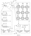
- FIG. 10 is a schematic representation of an example of light emitting element and sensor indexing (indicated by L and S, respectively).
- FIG. 11 is a flowchart representation of the method of directional lightbulb operation.
- FIG. 12 is a flowchart representation of a variation of determining a lightbulb position relative to a physical space.
- FIG. 13 is a flowchart representation of a first variation of determining a lightbulb position using signals emitted during the orientation process, including automatically determining the lightbulb position using a device.
- FIG. 14 is a flowchart representation of a first variation of determining a lightbulb position using signals emitted during the orientation process, including manually or pseudo-manually determining the lightbulb position.
- FIG. 15 is a schematic representation of a first example of selective lightbulb operation based on context, including cooperatively illuminating a first illumination target (a seating area) in a first context (reading), and cooperatively illuminating a second illumination target (a physical region behind the seating area) in a second context (movie).
- FIG. 16 is a schematic representation of a second example of selective lightbulb operation based on context, including cooperatively illuminating a first illumination target (the hallway) in a first context (tracking), and cooperatively illuminating a second illumination target (features on the walls) in a second context (spotlight).
- FIG. 17 is a schematic representation of an example of selective, cooperative lightbulb operation based on the spatial lighting pattern.
- FIG. 18 is a schematic representation of an example of pseudo-manual lightbulb position determination using a graphical representation of the lightbulb, and orientation-dependent lightbulb response.
- FIG. 19 is a schematic representation of an example of generating control instructions specifying an angular range of light emitting elements to be concurrently lit, control instruction receipt, and selective lightbulb operation based on the control instruction.
- FIG. 20 is a schematic representation of an example of proceeding the lightbulb through an orientation process according to an orientation pattern.
- FIG. 21 is a schematic representation of an example of determining the lightbulb position relative to a physical space using an external device.
- FIG. 22 is a schematic representation of an example of determining the lightbulb position relative to a physical space using a second lightbulb, further including an example of determining the position of the second lightbulb.
- FIG. 23 is a schematic representation of an example of determining the lightbulb position relative to a physical space using a connected appliance.
- FIG. 24 is a schematic representation of an example of selectively operating a lightbulb based on a spatial lighting pattern.
- FIG. 25 is a schematic representation of an example of mobile device triangulation.
- the directional lightbulb 100 includes a light emitting element 500 mounted in a fixed position on the lightbulb 100 , a communication module 400 , and a processor 700 electrically connected to the light emitting element 500 and the communication module 400 .
- the lightbulb 100 can additionally include a set of sensors 540 connected to the processor 700 , a substrate 520 supporting the light emitting element 500 and sensors 540 , and/or a diffuser 600 enclosing the light bulb components.
- the lightbulb 100 can include any other suitable set of components.
- the lightbulb 100 functions to selectively direct light relative to an external reference point 22 , such as toward a desired illumination target 60 .
- the lightbulb 100 preferably performs the method described below, but can alternatively be operated in any other suitable manner.
- the lightbulb 100 preferably enables light direction adjustment while the lightbulb 100 remains powered and physically connected to the power source, but can alternatively enable light direction adjustment after lightbulb 100 shutoff, cessation of power provision to the circuit to which the lightbulb 100 is connected, or enable light direction adjustment in any other suitable operation state.
- the lightbulb 100 directs light by selectively operating (e.g., selectively powering or turning on) individual light emitting elements positioned at select locations on the lightbulb 100 .
- the selectively controlled light emitting elements 500 are preferably those closest the desired illumination target 60 , but can alternatively be other light emitting elements 500 .
- the lightbulb position can be fixed within a lighting fixture 361 (e.g., a standard lighting fixture, such as a ceiling fixture, as shown in FIG. 17 ), and the light emitting elements 500 can be fixed in known positions on the lightbulb 100 .
- the lightbulb 100 selectively directs light by moving a powered light emitting element 500 (e.g., via the pivoted support 560 ) to point toward the desired illumination target 60 .
- the lightbulb 100 can be retained within a fixed lighting fixture, such that the lightbulb 100 moves the light emitting element 500 relative to the lightbulb base 360 , or be retained within a movable lighting fixture, such that the lightbulb 100 controls an external actuation mechanism to move the entire lightbulb 100 .
- the lightbulb 100 can otherwise direct light toward a desired illumination target 60 .
- This lightbulb 100 can confer several benefits over conventional lightbulbs 100 .
- the lightbulb 100 can reduce energy consumption by selectively powering only the light emitting elements 500 that are needed.
- the same lightbulb 100 can provide multiple different ranges of lighting angles. This can function to reduce the need to install additional lighting fixtures and lightbulbs 100 that selectively direct light toward different illumination targets 60 .
- the lightbulb 100 can determine and store its rotational and/or geographic position relative to an external reference point 22 . This relative orientation or position can subsequently be used to determine the position of the desired illumination target 60 relative to a reference point on the lightbulb 100 , and to determine each light emitting element's position relative to the desired illumination target 60 .
- the lightbulb 100 can be capable of rotationally orienting or geographically positioning itself using only the light emitting elements 500 and wireless communication system, using only the light emitting elements 500 and an ambient light sensor, using only the wireless communication system, or using any other suitable combination of components to rotationally or geographically orient itself in any other suitable manner.
- the lightbulb 100 rotational and/or geographic position can be automatically determined or manually determined.
- the lightbulb 100 rotational and/or geographic position can be determined solely by the lightbulb 100 , cooperatively determined with a user device, cooperatively determined with other similar lightbulbs 100 , or otherwise determined. Because the lightbulb 100 is mounted to a lighting fixture, which is typically static, the lightbulb 100 rotational and/or geographic position can be stored and reliably used for subsequent lighting events after initial position determination.
- lightbulb 100 variants including orientation or position sensors (e.g., accelerometers, gyroscopes, GPS systems, etc.), detection of movement beyond a threshold change (e.g., above 0.1 m/s 2 , 0.5 m/s 2 , 5 m/s 2 , 50 m/s 2 , etc.) can trigger position re-determination.
- a threshold change e.g., above 0.1 m/s 2 , 0.5 m/s 2 , 5 m/s 2 , 50 m/s 2 , etc.
- the lightbulb 100 orientation can be re-determined in response to switching of a reset switch, sudden cessation and/or power supply, or in response to any other suitable reset event.
- the lightbulb 100 can provide context-responsive lighting.
- the same lightbulb 100 (or plurality of lightbulbs 100 can anticipatorily light a user's path in the hallway while minimally lighting the hallway walls in a first context, and selectively illuminate paintings hung on the hallway walls (e.g., spotlight the paintings) while minimally lighting the hallway corridor in a second context.
- the same lightbulb 100 can provide downlight for a user reading a book on the couch in front of the television in a first context, or provide ambient backlight directed away from the television for the same user in the same location.
- FIG. 16 the same lightbulb 100 (or plurality of lightbulbs 100 can anticipatorily light a user's path in the hallway while minimally lighting the hallway walls in a first context, and selectively illuminate paintings hung on the hallway walls (e.g., spotlight the paintings) while minimally lighting the hallway corridor in a second context.
- the same lightbulb 100 can provide downlight for a user reading a book on the couch in front of the television in
- the same lightbulb 100 can simultaneously provide light having a first set of parameters to a first geographic region, and provide light having a second set of parameters to a second geographic region.
- the lightbulb 100 can flash light, in synchronization with flashes on a television, toward a first region of a couch, while concurrently providing a substantially constant light (e.g., for reading) toward a second region of the couch distinct from the first region.
- the lightbulb 100 can selectively operate the light emitting elements 500 in any other suitable manner in response to determination of any other suitable context.
- the lightbulb 100 can additionally confer any other suitable benefit.
- the lightbulb 100 preferably enables a plurality of light parameters to be automatically or manually controlled.
- controllable light parameters for each lightbulb 100 include: the light direction, which light emitting element 500 is lit, the emission pattern for each light emitting element 500 , the number of concurrently lit light emitting elements 500 , the pattern of concurrently lit light emitting elements 500 ′, the parameters of the emitted light (e.g., hue, saturation, brightness, correlated color temperature, color rendering index, attenuation, etc.), the shape of the emitted light (e.g., conical, beam, etc.), the quality of the emitted light (e.g., collimated, disperse, etc.), or include any other suitable light parameter.
- the parameters of the emitted light e.g., hue, saturation, brightness, correlated color temperature, color rendering index, attenuation, etc.
- the shape of the emitted light e.g., conical, beam, etc.
- the quality of the emitted light
- the parameters of a plurality or population of lightbulbs 100 can additionally be automatically or manually controlled to achieve a desired illumination effect within a physical space 20 or on an illumination target 60 .
- the population of lightbulbs 100 preferably includes all lightbulbs 100 within a physical space 20 (e.g., within a room, within a house, etc.), but can alternatively include all lightbulbs 100 arranged on the same sub-circuit, all lightbulbs 100 controlled by the same switch, all lightbulbs 100 connected to the same local area network (LAN), lightbulbs 100 located in geographically disparate locations, lightbulbs 100 associated with the same user account, or be any other suitable population of lightbulbs 100 .
- LAN local area network
- Examples of lightbulb population parameters that can be controlled include: which lightbulb 100 has lit light emitting elements 500 , the parameters of light emitted by each lightbulb 100 , when each lightbulb 100 is operated (e.g., relative timing between lightbulbs 100 ), the spatial light focus of the lightbulb population (e.g., wherein beams of low light from a first and second lightbulb 100 cooperatively illuminate a single volumetric region with a higher intensity than the emitted light, an example of which is shown in FIG. 17 ), or be any other suitable population parameter.
- the light emitting element 500 of the lightbulb 100 functions to emit electromagnetic radiation or signal 30 , such as light.
- the light emitting element can be an LED, OLED, solid-state light emitting element, or be any other suitable light emitting element.
- the lightbulb 100 preferably includes a plurality of light emitting elements 500 , but can alternatively include a single light emitting element 500 or any suitable number of light emitting elements 500 .
- Each light emitting element 500 can be independently controlled, such that each light emitting element 500 operates independently from the other light emitting elements 500 .
- a group of light emitting elements 500 can be independently controlled, such that the group of light emitting elements 500 can operate independently from the other of the light emitting elements 500 .
- Each controlled subset e.g., individual light emitting element 500 or cluster
- Each controlled subset is preferably wired in parallel relative to other controlled subsets of the lightbulb 100 , but can alternatively be wired in series, wired in a combination of in parallel and in series, or be wired in any other suitable manner.
- the controlled subsets of the lightbulb 100 are preferably controlled by the lightbulb 100 processor 700 , but can alternatively be controlled by a remote computing system 72 (e.g., server system), external device 30 (e.g., mobile device 70 , appliance, etc.), or by any other computing system.
- a remote computing system 72 e.g., server system
- external device 30 e.g., mobile device 70 , appliance, etc.
- Each controlled subset is preferably identified by a locally unique identifier (e.g., with respect to the lightbulb 100 ), such that the controlled subset can be individually controlled, but can alternatively be identified by a globally unique identifier, be identified by a nonunique identifier, or be identified in any other suitable manner.
- the identifier can be an index value (e.g., number), a position on the lightbulb 100 (component position, light emitting element position, etc.), or be any other suitable identifier. When an index is used, the index value for adjacently positioned subsets are preferably sequential (e.g., as shown in FIG.
- the subsets can alternatively be randomly or otherwise indexed, independent of the respective controlled subset position on the lightbulb 100 .
- the identifiers for each subset is preferably stored by the lightbulb 100 , but can alternatively be stored by a remote computing system (e.g., server system), external device 30 (e.g., mobile device 70 , appliance, etc.), or other computing system.
- the controlled subsets are preferably mounted in fixed positions on the lightbulb 100 , but can alternatively be mounted in movable positions or be otherwise affixed to the lightbulb 100 .
- the light emitting elements 500 are preferably mounted to a substrate 520 , which is mounted to a lightbulb housing 300 , but the light emitting elements 500 can alternatively be mounted to any other suitable lightbulb component.
- the light emitting elements 500 can be mounted on one or more broad faces of the substrate 520 , along one or more sides of the substrate 520 , or be mounted along any other suitable portion of the substrate 520 .
- the substrate 520 can be substantially flat, curved, polygonal, or have any other suitable configuration.
- the substrate 520 can additionally or alternatively include one or more protrusions (e.g., as shown in FIG. 3 ), divots, or other feature, wherein one or more controlled subsets are arranged on each feature.
- the substrate 520 can be substantially featureless.
- the light emitting elements 500 can be mounted in an array, in concentric rings (e.g., circles, rectangles, etc.; example shown in FIG. 9 ), in a spiral (e.g., circular spiral, logarithmic spiral, square spiral, etc.; example shown in FIG. 8 ), in a boustrophedonic pattern, randomly positioned, or be mounted in any other suitable pattern.
- the lightbulb 100 can additionally include a pivoted support 560 mounted to the light emitting element 500 that functions to selectively position the light emitting element 500 in one of a predetermined set of positions.
- the light emitting elements 500 can be statically retained relative to the lightbulb base 360 , housing 300 , or other component, and exclude a pivoted support 560 .
- the pivoted support 560 can rotate the light emitting element 500 about a rotational axis (e.g., rotate the light emitting element 500 45 degrees, 90 degrees, 180 degrees, 360 degrees, etc.), actuate the light emitting element 500 along an axis (e.g., along the lightbulb 100 longitudinal axis 10 , along a lightbulb 100 radial axis, etc.), or otherwise position the light emitting element 500 .
- the rotational axis can be the lightbulb 100 longitudinal axis 10 , an axis parallel to the lightbulb 100 longitudinal axis 10 , or an axis at a non-zero angle, such as 90 degrees, to the lightbulb 100 longitudinal axis 10 , or be any other suitable rotational axis.
- the pivoted support 560 is preferably mounted to the substrate 520 , but can alternatively be mounted to individual controlled subsets (e.g., wherein the substrate 520 can be formed from multiple components), groups of controlled subsets, or be mounted to any other suitable set of light emitting elements 500 .
- the pivoted support 560 is preferably mounted at the other end to the lighting housing 300 or base 360 , but can alternatively be mounted to any other suitable component.
- the pivoted support 560 preferably actuates the light emitting elements 500 relative to the base 360 of the lightbulb 100 , but can alternatively actuate the light emitting elements 500 relative to the lightbulb housing 300 , the lightbulb 100 diffuser boo, or any other suitable lightbulb component. Alternatively or additionally, the pivoted support 560 can actuate the light emitting elements 500 relative to an external reference point 22 (e.g., wherein the pivoted support 560 rotates the light fixture 361 ).
- the pivoted support 560 can be active (e.g., driven by a motor, electromagnet, or other actuation mechanism) or passive.
- the pivoted support 560 can additionally include a position sensor that measures the position (e.g., angular position, radial position, etc.) of the light emitting element 500 or substrate 520 .
- a position sensor that measures the position (e.g., angular position, radial position, etc.) of the light emitting element 500 or substrate 520 .
- the position sensor include a rotary sensor (e.g., an optical encoder, magnetic encoder, capacitive encoder, mechanical encoder, geared encoder, battery-powered encoder, self-powered multi-turn encoder, etc.), linear encoder (e.g., optical, magnetic, capacitive, inductive, eddy current, etc.), or be any other suitable encoder.
- the pivoted support 560 can be a gimbal system, a ball and joint, a knuckle joint, a turnbuckle, a pin joint, a cotter joint, or any other suitable joint; a scissor lift, linear actuator, or any other suitable actuation mechanism.
- each controlled subset on the lightbulb 100 is preferably known and stored in association with the respective identifier, but can alternatively be otherwise determined.
- the subset position for each subset on the lightbulb 100 can be determined by the manufacturer, automatically by the lightbulb 100 , by an external device 30 (e.g., a mobile device 70 or appliance), or be determined by any other suitable system.
- the subset position for each subset is preferably stored by the lightbulb 100 , but can alternatively be stored by a remote computing system (e.g., server system), external device 30 (e.g., mobile device 70 , appliance, etc.), or other computing system.
- the position of each controlled subset is preferably a position relative to a reference point on the lightbulb 100 (lightbulb 100 reference point), but can alternatively be a location within a grid, wherein each grid intersection is a known, fixed distance from the next grid intersection, or be otherwise determined.
- the lightbulb 100 reference point can be a real reference point or an imaginary reference point.
- the lightbulb 100 reference point can be a light emitting element 500 (e.g., a first light emitting element 500 ), a controlled subset, a sensor 540 (e.g., a light sensor), a notch on the lightbulb 100 , a lightbulb longitudinal axis 10 , a position determined by a rotary encoder, or be any other suitable reference point.
- the reference point is preferably static, but can alternatively move, wherein the lightbulb 100 can track the new reference point position and determine new position coordinates for each light emitting element 500 .
- the light emitting elements 500 can be LEDs (light emitting diodes), OLEDs (organic light emitting diodes), PLEDs (polymer LEDs), solid-state lighting, LECs (light emitting electrochemical cells), other electroluminescent lighting, lasers, bioluminescent lighting, chemoluninescent lighting, fluorescent lighting, gas discharge lighting, phosphorescent lighting, ESL lighting, incandescent lighting, or be any other suitable component capable of emitting electromagnetic or blackbody radiation 30 .
- LEDs light emitting diodes
- OLEDs organic light emitting diodes
- PLEDs polymer LEDs
- solid-state lighting LECs (light emitting electrochemical cells), other electroluminescent lighting, lasers, bioluminescent lighting, chemoluninescent lighting, fluorescent lighting, gas discharge lighting, phosphorescent lighting, ESL lighting, incandescent lighting, or be any other suitable component capable of emitting electromagnetic or blackbody radiation 30 .
- the radiation 30 emitted by the light emitting elements 500 can be visible or invisible, and can include the entire visible spectrum, portions of the visible spectrum (e.g., red, green, and blue; deep red; etc.), portions of the invisible spectrum (e.g., IR, etc.), or include any other suitable portion of the electromagnetic spectrum.
- Each light emitting element 500 of the lightbulb 100 is preferably substantially identical, but can alternatively be different.
- the light emitting elements 500 are all capable of emitting the same plurality of colors (e.g., white only, blue, red, and green, full color, etc.) and/or be the same type of light emitting element 500 (e.g., be RGB LEDs).
- the light emitting elements 500 are grouped into clusters, wherein each cluster is independently controllable and includes the same combination of light emitting elements 500 .
- each cluster can include a red, blue, and green light emitting element 500 .
- the majority of the light emitting elements 500 can be substantially similar (e.g., emit the same colors, include substantially the same group of light emitting elements 500 , etc.), while a minority of light emitting elements 500 can have different properties (e.g., be a different type of light emitting element 500 , emit light at a different frequency, such as deep red, etc.).
- the majority of light emitting elements 500 can be white LEDs, but include one or more (e.g., one, two, five, etc.) deep red LEDs or IR LEDs.
- the lightbulb 100 can include any other suitable set of light emitting elements 500 arranged and controlled in any other suitable manner.
- the set of light emitting elements can additionally include a set of dividers that separate light emitting elements or controlled subsets.
- the dividers preferably separate adjacent, individually indexed controlled subsets, but can alternatively separate adjacent groups of controlled subsets or be arranged in any other suitable position.
- the lightbulb can exclude dividers, such that the physical space between adjacent controlled subsets is substantially unobstructed.
- the divider can be opaque, transparent, translucent, or have any other suitable optical property.
- the divider optical properties can be fixed or adjustable (e.g., adjusted by applying a variable voltage to the divider).
- the divider can extend a portion of the distance between the adjacent controlled subsets (e.g., be half length), extend along the entirety of the distance between the adjacent controlled subsets, or have any other suitable length.
- the divider can extend a portion of the distance from the substrate to the diffuser or outer covering (e.g., be half height), extend the full distance between the substrate and the diffuser, or have any other suitable height.
- the divider can have any other suitable dimension.
- the divider can be formed between channels defined within the substrate 520 (e.g., wherein the light emitting elements can be arranged within the channels), defined by protrusions extending from the substrate, or be otherwise defined.
- the communication module 400 of the lightbulb 100 functions to communicate data between the lightbulb 100 and a secondary device.
- the secondary device can be a LAN node (e.g., a router), a second lightbulb 100 , a mobile device 70 associated with a user (e.g., a smartphone, tablet, smartwatch, etc.), a connected appliance (e.g., a television, switch, etc.), or be any other suitable secondary device.
- the communication module 400 can support wireless and/or wired communication.
- the wireless communication module 400 preferably includes a transceiver, but can alternatively be a transmitter or a receiver. Additionally or alternatively, the wireless communication module 400 can be a router.
- the communication module 400 preferably supports one or more communication protocol standards, but can alternatively support any other suitable communication protocol.
- the communication module 400 can be mounted on the substrate 520 , mounted to the processor board, mounted to a separate and distinct board, mounted to the lightbulb housing, or be mounted to any other suitable lightbulb component.
- the wireless communication module 400 preferably includes an antenna 430 electrically connected to the processor 700 of the lightbulb 100 , and can additionally include intervening circuitry that supports the communication protocol.
- the antenna 430 extends through the substrate 520 (e.g., along the longitudinal axis 10 of the lightbulb 100 ), such that the substrate 520 can rotate about the antenna 430 in articulating variants.
- the antenna 430 extends along a radial or lateral portion of the lightbulb housing 300 (e.g., as shown in FIG. 5 ).
- the lightbulb 100 can include one or more communication modules 400 , wherein different modules of the plurality can support the same or different communication protocols.
- the communication protocol can be WiFi, WiMAX, mesh, zigbee, Z-WAVE, wireless USB, UWB, thread, IR, US, radio, cell, GPS, satellite, NFC, RF, Bluetooth, microwave, modulated light, powerline, Ethernet, coaxial cable, ITU-TG.hn, twisted pair wire, optical fiber, or be any other suitable communication protocol.
- the processor 700 of the lightbulb 100 functions to operate the light emitting elements 500 according to control instructions 50 .
- the control instructions 50 can be received from the secondary device through the communication module 400 , retrieved from on-device storage (e.g., volatile or non-volatile lightbulb 100 memory), automatically generated by the processor 700 based on sensor measurements or received information, or be determined in any other suitable manner.
- on-device storage e.g., volatile or non-volatile lightbulb 100 memory
- the processor 700 can additionally or alternatively index the light emitting elements 500 , selectively control the light emitting elements 500 based on the respective index value or light emitting element position, determine the gravitational or rotational position of the lightbulb 100 (e.g., a reference point on the lightbulb 100 ) relative to an external reference point 22 (e.g., by progressing the lightbulb 100 through an orientation pattern), determine the occurrence of contextual events and operate the light emitting elements 500 based on control instructions 50 associated with the contextual events, or otherwise operate the lightbulb 100 .
- the processor 700 can additionally store the position of the lightbulb 100 relative to the external reference point 22 , such that the processor 700 can repeatedly illuminate the desired illumination target 60 for each determined context.
- the processor 700 is preferably a CPU, but can alternatively be a microprocessor 700 , a GPU, or any other suitable processing unit.
- the processor 700 is preferably electrically connected to the active components of the lightbulb 100 (e.g., light emitting elements 500 , communication module 400 , pivoted support 560 , sensors 540 , etc.), but can alternatively be connected to a subset of the active components, or be connected to any other suitable set of components.
- the processor 700 is preferably mounted to the substrate 520 , but can alternatively be mounted to the communication module 400 or be mounted to any other suitable portion of the lightbulb 100 .
- the lightbulb 100 can additionally include a set of sensors 540 that function to measure lightbulb 100 parameters and/or ambient environment parameters.
- the sensors 540 are preferably arranged on the substrate 520 (e.g., on the same, adjacent, or opposing face as the light emitting elements 500 ), but can alternatively be arranged along the housing 300 (e.g., as shown in FIG. 2 ), the diffuser 600 , the base 360 , or be arranged along any other suitable lightbulb component.
- the sensors 540 are preferably electrically connected to the processor 700 , but can alternatively be electrically connected to the communication module 400 or be otherwise connected.
- sensors 540 can include light sensors, positioning systems, orientation sensors, power sensors, sound sensors, or include any other suitable sensor.
- Light sensors can include ambient light sensors (e.g., photometers, photodiodes, photoresistors, phototransistors, etc.), image sensors or cameras (e.g., CCD cameras, CMOS cameras, etc.), optical detectors, or be any other suitable light sensor.
- the lightbulb 100 excludes a camera. However, the lightbulb 100 can leverage the feed from an on-board or external camera, or function in any other suitable manner.
- Positioning systems can include GPS units, cellular triangulation units, trilateration units, optical sensing system, such as a LIDAR system, acoustic sensing system, or be any other suitable positioning system.
- Orientation sensors can include accelerometers, gyroscopes, digital compasses, or any other suitable orientation sensors.
- Power sensors can include Hall effect sensors, voltage sensors, or any other suitable sensor capable of measuring a power parameter.
- Sound sensors can include microphones, transducers, or any other suitable sound sensor.
- the lightbulb 100 can include any other suitable set of sensors.
- the lightbulb 100 can additionally include a diffuser 600 and housing 300 , which function to encapsulate the lightbulb components.
- the diffuser 600 can additionally function to diffuse the light emitted by the light emitting elements 500 , particularly when the light emitting elements 500 are LEDs (e.g., to increase the diffusion angle).
- the diffuser 600 is preferably statically coupled to the housing 300 or substrate 520 , but can alternatively be actuatable.
- the diffuser 600 preferably has a substantially static translucency, but can alternatively have a translucency that can be dynamically adjusted (e.g., by the processor 700 ).
- the diffuser 600 preferably has a substantially constant translucency over its surface, but can alternatively have a variable translucency over its surface.
- the diffuser 600 preferably encapsulates the sensors (e.g., the ambient light sensor) within the lightbulb 100 (e.g., as shown in FIG. 1 ), but can alternatively include apertures or other features to expose the sensors to the ambient environment
- the housing 300 can additionally function to cool the active components and/or function as a structural support for the active components.
- the power source is preferably a lighting fixture 361 , more preferably a standard light fixture (e.g., a ceiling socket or lamp) that is connected to a local circuit, which in turn, is connected to a power grid (as shown in FIG. 7 ), but can alternatively be a battery, renewable system, or be any other suitable power source.
- the housing 300 can include a base 360 , which functions to electrically connect the lightbulb 100 to a power source.
- the base 360 is preferably a standard lightbulb base 360 (e.g., an Edison screw, bayonet, bi-post, bi-pin, wedge, fluorescent base 360 , etc.), but can alternatively be a custom base 360 or any other suitable type of base 360 .
- the lightbulb 100 can be directly wired into the local circuit or be otherwise powered.
- the method of spatial lightbulb operation includes determining the position of the lightbulb relative to a physical space S 100 , detecting a contextual event S 200 , determining a spatial lighting pattern associated with the contextual event S 300 , and selectively controlling lightbulb light emitting elements based on the position of the lightbulb and the spatial lighting pattern S 400 .
- the method functions to automatically determine the rotational and/or gravitational lightbulb orientation within the space.
- the method can additionally function to automatically operate the lightbulb to illuminate desired illumination targets with light having a desired set of parameters in response to the occurrence of contextual events.
- the method is preferably performed with the lightbulb described above, but can alternatively be performed with any other suitable lighting system.
- Determining the position of the lightbulb relative to a physical space (lightbulb position) S 100 functions to spatially orient the lightbulb.
- determining the lightbulb position S 100 can include determining the physical position of the lightbulb within the physical space, determining the angular or rotational position of the lightbulb relative to an external reference point, determining the pitch of the lightbulb relative to a gravity vector, and/or determining the lightbulb yaw relative to a gravity vector.
- Determining the lightbulb position can additionally include: associating a reference point on the lightbulb (lightbulb reference point) with a reference point external the lightbulb (external reference point), such that the relationship can subsequently be used to determine which light emitting elements to operate to illuminate a desired external illumination target with minimal or no additional orientation input.
- the lightbulb position is preferably automatically determined by the lightbulb, but can alternatively be cooperatively determined (e.g., with the lightbulb) or entirely determined by an external device within the physical space (e.g., a second lightbulb, a mobile device, an appliance, etc.), a remote system 72 outside of the physical space (e.g., a remote server system), or any other suitable system.
- determining the lightbulb position S 100 includes progressing the lightbulb through an orientation process S 110 (e.g., operating the lightbulb in an orientation mode) and determining the lightbulb position by using signals emitted during the orientation process S 120 , as shown in FIG. 12 .
- the lightbulb position can be otherwise determined.
- the lightbulb position can be automatically determined by only the lightbulb, be cooperatively determined by the lightbulb and an external device, or be determined by any other suitable system.
- the orientation process functions to operate lightbulb components having known positions, such that the lightbulb or an external device can index the rotational orientation of the lightbulb.
- the orientation process preferably includes sequentially operating individual controlled subsets in a predetermined mode in a predetermined pattern.
- the orientation process can additionally include identifying an associative variable for use in automated lightbulb position determination.
- the controlled subset can be an individual light emitting element (e.g., as shown in FIG. 21 ), a cluster or group of light emitting elements (e.g., as shown in FIG. 20 ), or be any other suitable set of lightbulb components.
- Each controlled subset is preferably individually identified, such that it has a locally unique identifier (e.g., index value), but can alternatively share an identifier with a second controlled subset of the lightbulb, or be otherwise identified.
- Each controlled subset (or the respective identifier) is preferably associated with a known, stored spatial position on the lightbulb (controlled subset position).
- the controlled subset position can include the arcuate position, radial position, position along an axis (e.g., along the longitudinal axis), set of coordinates, grid position, or be any other suitable position.
- the controlled subset positions are preferably stored by the lightbulb 100 (e.g., on volatile or non-volatile memory), but can alternatively or additionally be stored by the remote system 72 , external device 30 , or by any other suitable system.
- the predetermined mode is preferably for a controlled subset, and can be associated with a set of light emitting element operation parameter values, such as values for emitted light parameters (e.g., intensity, color, collinearity, etc.), light emission duration or frequency, or any other suitable operation parameter.
- Operating the controlled subset in the predetermined mode can include controlling the controlled subset based on the operation parameter values or controlling the controlled subset to meet the operation parameter values.
- the predetermined mode for each controlled subset is preferably substantially similar in the orientation process (e.g., same brightness or intensity, same color, same dispersion, etc.), but can alternatively be different for each controlled subset. However, the operation parameter values can be otherwise used.
- predetermined modes examples include a high emission mode, a low emission mode, a strobe mode, a user-defined mode, or be any other suitable mode.
- the controlled subset can be controlled to emit substantially constant high intensity light (e.g., 100% power, over 50% power, etc.) in a wavelength detectable by a sensor or a human eye (e.g., visible light).
- substantially constant light can be light that is perceived as constant by a human eye, light that oscillates at a frequency of 50 Hz or higher (e.g., when PWM is used), or be achieved in any other suitable manner.
- the controlled subset In the low emission mode, the controlled subset can remain unpowered, be controlled to emit substantially constant low intensity light, be controlled to emit non-visible or low-detectability light, or be controlled to meet any other suitable set of parameter values. In the strobe mode, the controlled subset can be controlled to switch between the high and low emission mode at a predetermined frequency. However, the orientation pattern can specify any other suitable operation mode.
- the predetermined pattern can include sequentially operating adjacent controlled subsets (e.g., adjacent light emitting elements), sequentially operating the controlled subsets according to the respective index value (e.g., operating controlled subset 1 , then operating controlled subset 2 ), randomly operating the controlled subsets, sequentially operating every other adjacent controlled subset, concurrently operating multiple controlled subsets (e.g., concurrently operating light emitting elements on a first half of the lightbulb, concurrently operating the outer ring of light emitting elements, etc.), or include any other suitable pattern of light emitting element operation.
- the lightbulb preferably tracks the identifier of each controlled subset being operated in the pattern and the timestamp at which the respective controlled subset is operated, but can alternatively track any other suitable orientation process parameter.
- the predetermined pattern includes operating a first light emitting element in the high emission mode while operating the remainder of the light emitting elements in a low emission mode, then operating a second light emitting element adjacent the first light emitting element in the high emission mode while operating the remainder of the light emitting elements (including the first light emitting element) in a low emission mode, and repeating the process for each successive light emitting element on the entire lightbulb or lightbulb segment (e.g., perimeter).
- the predetermined pattern can be substantially similar to the first example, except that instead of the second light emitting element being the light emitting element adjacent the first light emitting element, the second light emitting element can be the light emitting element located a predetermined number of light emitting elements away from the first light emitting element. In a specific example, every other light emitting element can be sequentially operated in the high emission mode.
- the predetermined pattern includes concurrently operating a first plurality of light emitting elements (e.g., on a first half of the lightbulb) in a high emission mode while operating a second plurality of light emitting elements (e.g., on a second half of the lightbulb) in a low emission mode, then concurrently operating the second plurality of light emitting elements in the high emission mode while operating the first plurality of light emitting elements in the low emission mode.
- the first and second pluralities can be separate and distinct, overlap, or be related in any other suitable manner.
- the light emitting elements can be operated in any other suitable pattern during the orientation process.
- Identifying an associative variable functions to determine a variable that can be used to link a detected signal with the controlled subset that emitted the signal. Because the position of the controlled subset on the lightbulb is known, this information can be used to determine the rotational orientation of the lightbulb relative to the external reference point.
- the associative variable can be a timestamp.
- a set of timestamps can be recorded and associated with a controlled subset identifier when the respective controlled subset is operated in the predetermined mode.
- the timestamp can subsequently be used to determine which controlled subset emitted the detected light (e.g., by an external device or the lightbulb).
- the associative variable can be the controlled subset identifier.
- the controlled subset identifier can be communicated as part of the signal emitted by the respective controlled subset (e.g., thorough light modulation).
- any other suitable associative variable can be used.
- Determining the lightbulb position using signals emitted during the orientation process S 120 functions to determine the rotational orientation of the lightbulb, and can additionally function to determine the lightbulb location within the physical space, the lightbulb yaw, lightbulb pitch, or determine any other suitable lightbulb position parameter.
- a device detects the signals emitted during the orientation process and determines the value of the associative variable corresponding to the detected signal.
- determining the lightbulb position using signals emitted during the orientation process S 120 preferably includes measuring the incident signal with the device S 122 , determining the associative variable corresponding to an incident signal measurement of interest S 124 , determining an external reference point identifier S 126 , and associating a variable of the controlled subset identified by the associative variable with the external reference point identifier S 128 , as shown in FIG. 13 .
- the lightbulb position can be otherwise determined using signals emitted during the orientation process.
- Measuring the incident signal with the device S 122 functions to measure the relative strengths of the emitted signal received at the device.
- the incident signal is preferably measured concurrently (e.g., during) lightbulb progression through the orientation process, but can be measured at any other suitable time.
- the incident signal is preferably the signal emitted by the lightbulb during the orientation process, such as light or other electromagnetic signals emitted by the lightbulb. However, any other suitable incident signal can be measured.
- measuring the incident signal S 122 includes measuring the signal with a device is external the lightbulb (external device), as shown in FIG. 21 .
- the external device can be a mobile device, an appliance, a second lightbulb, or be any other suitable external device.
- the external device can additionally record or determine the associative variable corresponding to each measurement (e.g., record a timestamp, as shown in FIGS. 21 and 22 ; determine a controlled subset identifier, as shown in FIG. 23 ; etc.).
- data associated with the measurements can be transmitted from the external device to the system associating the controlled subset variable with the associative variable (e.g., the lightbulb 100 , remote system 72 , mobile device 70 , etc.), in variants where the external device does not perform the association.
- the data can be communicated through a LAN enabled by an external router, a peer-to-peer network, or through any other suitable communication channel.
- measuring the incident signal includes measuring the signal with the lightbulb.
- the incident signal can be otherwise measured.
- the mobile device When the external device is a mobile device (e.g., smartphone, tablet, etc.), the mobile device, more preferably a light sensor of the mobile device (e.g., an ambient light sensor, camera, etc.) or any other suitable mobile device component, can detect the incident light emitted by the lightbulb as the lightbulb progresses through the orientation process.
- the mobile device can additionally record the timestamp at which each incident light measurement was recorded, determine the controlled subset identifier from the incident light, or determine any other suitable associative variable value.
- the external reference point identifier can be the absolute or relative geographic location of the mobile device, which can be automatically determined by the mobile device (e.g., the GPS system, cell triangulation system, beacon triangulation system, etc.), or be determined by any other suitable system.
- the external reference point identifier can be the location of the mobile device during the orientation process, the location of the mobile device measured while the incident light is being measured, the location of the mobile device measured within a threshold time duration of the incident light measurement, the location of the mobile device measured within a threshold time duration of light emission, the location of the mobile device measured within a threshold time duration of the orientation process, be the location of the mobile device entered by the user, or be the mobile device location measured any other suitable time.
- the external reference point identifier can be received from a user in association with the orientation process.
- the external reference point identifier is preferably received from the user at the mobile device and subsequently communicated to the lightbulb or a remote system associated with the lightbulb, but can alternatively be otherwise received.
- the external reference point identifier can be a geographic location identifier (e.g., venue name, such as “couch,” “stove,” “preparation station,” geographic coordinates, physical object identifier, such as “painting,” etc.), an identifier for a second external device (e.g., “television,” “oven,” “stove,” etc.), or be any other suitable identifier.
- the mobile device is preferably located proximal the external reference point associated with the external reference point identifier when the mobile device detects the incident light, but can alternatively be arranged in another location.
- the appliance when the external device is an appliance, the appliance, more preferably a light sensor or camera of the appliance but alternatively any other suitable component, can measure the incident signal emitted by the lightbulb as the lightbulb progresses through the orientation process.
- the appliance can be substantially static (e.g., be a fixture), or can be mobile.
- the appliance can be a connected appliance having wired or wireless communication capabilities, or be disconnected. Examples of appliances include televisions, ovens, or other fixtures.
- the appliance can record the timestamp at which each incident light measurement was recorded, determine the controlled subset identifier from the incident light, or determine any other suitable associative variable value.
- the external reference point identifier can be the appliance identifier (e.g., a descriptor, such as “television 1 ,” an SKU number, a user-specified identifier, or be any other suitable identifier), an example of which is shown in FIG. 23 ; an appliance geographical location (entered by the user or automatically determined by the appliance); or be any other suitable identifier.
- the appliance identifier e.g., a descriptor, such as “television 1 ,” an SKU number, a user-specified identifier, or be any other suitable identifier
- the second lightbulb When the external device is a second lightbulb, the second lightbulb, more preferably a light sensor or camera of the second lightbulb but alternatively any other suitable component, can measure the incident signal emitted by the first lightbulb as the first lightbulb progresses through the orientation process.
- the second lightbulb is preferably arranged within the same physical space as the first lightbulb, more preferably connected to the same sub-circuit as the first lightbulb, but can alternatively be arranged in any other suitable position.
- the first and/or second lightbulbs can determine whether they are on the same sub-circuit based on the power provision time, based on whether they can communicate with each other using short-range communication protocols, or determine that they are on the same sub-circuit in any other suitable manner.
- the second lightbulb preferably measures the incident signal at a sensor located on-board the second lightbulb, but can otherwise measure the incident signal.
- the sensor can be an ambient light sensor (e.g., wherein the signal is light), a microphone (e.g., wherein the signal is sound), or be any other suitable sensor.
- the second lightbulb light sensor is enclosed within the lightbulb by the diffuser, the second lightbulb is preferably operated in the low emission mode during the orientation process to prevent measurement contamination by secondary light emitted by the second lightbulb.
- the second lightbulb can operate all or a subset of its light emitting elements in the high emission mode and automatically correct for the measurement contamination.
- the second lightbulb can be operated in any suitable mode.
- the second lightbulb preferably includes a plurality of sensors, but can alternatively include a single sensor or a pair of sensors. Each sensor can be associated with a sensor identifier and a sensor position on the lightbulb.
- the sensor positions (spatial orientations) on the second lightbulb are preferably fixed, known, and stored.
- the second lightbulb can record the timestamp at which each incident signal measurement was recorded, determine the controlled subset identifier from the incident signal, or determine any other suitable associative variable value.
- the external reference point identifier can be the second lightbulb identifier, an identifier for a sensor of the second lightbulb (sensor identifier), a second lightbulb geographical location (entered by the user or automatically determined by the second lightbulb), or be any other suitable identifier.
- the second lightbulb includes a plurality of light sensors arranged in fixed, known positions on the lightbulb, wherein the external reference point identifier can be the identifier for the sensor that measured the brightest incident light emitted by the first lightbulb.
- the second lightbulb can determine its position relative to the first lightbulb. This can enable the first lightbulb to know the angular position of the second lightbulb relative to the first lightbulb, and enable the second lightbulb to know the angular position of the first lightbulb relative to the second lightbulb.
- the second lightbulb can determine which of its sensors is most proximal the first lightbulb. The sensor most proximal the first lightbulb can be the sensor that measured the brightest incident light, the sensor that measured incident light for the longest time duration or for the highest number of controlled subset operations, or be characterized in any suitable manner.
- the second lightbulb can triangulate the relative position of the first lightbulb based on the stereovision. However, the position of the second lightbulb relative to the first lightbulb can be otherwise determined.
- measuring the incident signal S 122 includes measuring the signal with the lightbulb, such that the lightbulb can subsequently automatically determine its own position.
- the lightbulb can emit the light during the orientation process, measure the light reflected off of adjacent surfaces, and automatically determine its position relative to adjacent surfaces based on the incident light.
- the lightbulb preferably includes one or more sensors that measure the reflected light. The sensors are preferably arranged on the lightbulb exterior (e.g., to prevent light measurement contamination), but can alternatively be arranged behind the diffuser or be otherwise arranged.
- the lightbulb can determine the relative distance of the adjacent surface (e.g., based on the intensity of the reflected light), the curvature of the adjacent surface, the material of the adjacent surface, or determine any other suitable parameter of the adjacent surface.
- the lightbulb can additionally coordinate with adjacent lightbulbs, such that two adjacent lightbulbs are not concurrently operated in the orientation mode (e.g., to prevent measurement interference). However, the lightbulb can otherwise automatically determine its position relative to adjacent surfaces.
- Determining the associative variable corresponding to an incident signal measurement of interest S 124 functions to identify the controlled subset (indexing controlled subset) that is spatially related to the external reference point.
- the incident signal measurement of interest can be the strongest incident signal measured during the orientation process (e.g., brightest or most intense measured light), weakest incident signal measured during the orientation process (e.g., dimmest or least intense measured light), the signal measurement having a value exceeding a threshold value (e.g., measuring light over threshold intensity), or be any other measurement having signal parameters of interest.
- the associative variable preferably corresponds to the signal measurement of interest, but can be any other associative variable.
- the associative variable can be a timestamp (e.g., a recordation timestamp at which the incident signal is measured, etc.), a controlled subset identifier, or be any other suitable associative variable.
- the signal measurement of interest and/or corresponding associative variable can be determined by the device, by the remote system, by the lightbulb, or by any other suitable system.
- the device preferably communicates the measurements (raw or processed) to the processing system.
- the timestamp at which the measured incident light exceeds a threshold intensity is identified as the recordation timestamp of interest.
- the threshold intensity can be determined based on the intensity of the emitted light (e.g., be more than 80% of the emitted light intensity, substantially match the emitted light intensity, etc.), the ambient light intensity prior to orientation process initiation, or based on any other suitable variable value.
- Determining an external reference point identifier S 126 functions to determine an identifier that can be subsequently used to identify the external reference point, such as for context-related illumination.
- the external reference point identifier can be received from a user, automatically determined by the device, automatically determined by the lightbulb, or be otherwise determined.
- the external reference point identifier can be a geographic location, a label, a device identifier, or be any other suitable identifier of the external reference point.
- Associating the variable of the controlled subset, identified by the associative variable, with the external reference point identifier S 128 functions to spatially relate a lightbulb reference point with the external reference point.
- the association is preferably stored for use in contextual control.
- the association can be stored by the lightbulb, remote system, mobile device, or other system.
- the lightbulb preferably determines which controlled subset is identified by the associative variable, but the controlled subset can alternatively be determined by a remote system, the external device, or by any other suitable system.
- the recordation associative variable (measured by the external device) corresponding to the signal measurement of interest is preferably matched or otherwise correlated with an orientation associative variable (recorded by the lightbulb during the orientation process), wherein the controlled subset that emitted signals corresponding to the orientation associative variable is preferably the controlled subset associated with the external reference point.
- the associative variable is a timestamp.
- the recordation timestamp corresponding to the brightest light measured by the external device is substantially matched (e.g., matched within a time duration margin of error, such as 0.5 s, 2 milliseconds, or any other suitable time duration margin of error, to accommodate for signal travel time or signal transmission time from the lightbulb to the external device, etc.) to the origination timestamp, wherein the LED that was lit during the origination timestamp can be the controlled subset for which variables are associated with the external reference point.
- a time duration margin of error such as 0.5 s, 2 milliseconds, or any other suitable time duration margin of error
- the controlled subset that is associated with the external reference point can be the controlled subset that is proximal (or most proximal) the identified external reference point, but can alternatively be the controlled subset that is distal (or most distal) the identified external reference point or be the controlled subset positioned in a predetermined orientation relative to the external reference point.
- the controlled subset variable is preferably associated with an angular position on the lightbulb, such that an angular position of the lightbulb is associated with the external reference point.
- the controlled subset variable can be associated with any other suitable parameter.
- the controlled subset variable can be the controlled subset identifier, the controlled subset position on the lightbulb, the position of the controlled subset relative to a reference point on the lightbulb (e.g., a notch position), or be any other suitable variable of the controlled subset.
- the controlled subset variable is preferably stored in association with the external reference point identifier, but can alternatively be otherwise associated with the external reference point identifier.
- the fifth indexed LED is associated with a television when the brightest light emitted by the lightbulb, as determined by the television, was emitted by the fifth indexed LED.
- the method can additionally include determining the absolute location of the lightbulb within a physical space.
- the position of the lightbulb can be determined based on the angle of the incident light at the mobile device, the incident light parameters (e.g., phase and intensity), the heading of the mobile device (e.g., based on a digital compass), and the angular orientation of the mobile device relative to a gravity vector (e.g., based on the accelerometer).
- the mobile device parameters can be used to determine the location and orientation of the mobile device, the incident light angle can be used to determine the angular position and direction of the lightbulb relative to the mobile device, and the phase and/or intensity difference between the emitted light and measured light can be used to determine the distance of the lightbulb away from the mobile device.
- the phase and/or intensity differences can additionally or alternatively be used to determine the yaw, pitch, or other orientation parameter of the lightbulb.
- these lightbulb orientation parameters can be determined by lightbulb sensors, cooperatively determined by the lightbulb and signals measured by the external device, or otherwise determined.
- the lightbulb position is pseudo-manually determined.
- the user can control which controlled subset is lit during the orientation process, and manually associate an external reference point identifier with the lit controlled subset.
- the method can include receiving a control instruction from a device associated with a user S 121 (e.g., through a logged in user account), controlling the lightbulb based on the control instructions S 123 , detecting a controlled subset selection event S 125 , receiving an external reference point identifier S 127 a (and/or context label S 127 b ), and associating variable(s) of the selected controlled subset(s) with the external reference point identifier S 129 a (or context label S 129 b ), as shown in FIG. 14 .
- individual controlled subsets (e.g., light emitting elements) of the lightbulb can be sequentially lit (example of S 123 ) as the user scrolls through a complimentary lightbulb representation on the user interface of a mobile device (example of S 121 ) (e.g., by entering a control instruction, such as a light control vector, which can be linear, arcuate, or have any other suitable shape).
- a control instruction such as a light control vector, which can be linear, arcuate, or have any other suitable shape.
- the direction that the controlled subsets are sequentially lit is preferably determined based on the orientation of the lightbulb relative to a gravity vector, but can be otherwise determined.
- the orientation of the lightbulb relative to a gravity vector is preferably determined by the orientation sensor of the lightbulb (e.g., accelerometer, gyroscope, etc.), but can be otherwise determined.
- the orientation sensor of the lightbulb e.g., accelerometer, gyroscope, etc.
- receipt of a clockwise control instruction e.g., clockwise control vector
- can control sequential light emitting elements to be lit in a counterclockwise pattern e.g., sequentially lit to the left when viewed end-on from the diffuser.
- receipt of a clockwise control instruction can control sequential light emitting elements to be lit in a clockwise pattern (e.g., sequentially lit to the right) when viewed end-on from the diffuser.
- Receipt of a counterclockwise control vector can control the light emitting elements to be lit in the opposite manner.
- the lightbulb orientation relative to a gravity vector can be otherwise accommodated.
- the user can enter an external reference point identifier (example of S 127 a ), such as a label (e.g., “painting,” “wall,” “television,” etc.), geographic location, or any other suitable external reference point identifier that will subsequently be associated with the selected controlled subsets.
- an external reference point identifier such as a label (e.g., “painting,” “wall,” “television,” etc.), geographic location, or any other suitable external reference point identifier that will subsequently be associated with the selected controlled subsets.
- a context label example of S 127 b
- the user can enter a context label (example of S 127 b ), such as “night,” “party,” or any other suitable contextual label.
- the method can additionally include verifying or confirming the selected controlled subsets.
- the mobile device can verify that the emitted light is being received at the mobile device location using the ambient light sensor of the mobile device.
- the mobile device can be controlled to display a query, requesting the user to verify that the emitted light is illuminating the desired illumination target.
- the controlled subset selection can be otherwise verified.
- the user can additionally specify the number of lit light emitting elements (e.g., by entering the number, dragging two fingers apart on the lightbulb representation, etc.), rotate the lit set of light emitting elements about the lightbulb until the lit set of light emitting elements illuminate a desired illumination target (e.g., television, wall, table), and enter a descriptor for the illuminated target (e.g., “television,” “wall,” “table,” respectively), which functions as the external reference point identifier.
- the external reference point identifier can be stored in association with the controlled subset variable (e.g., position, identifier, etc.) of the selected controlled subset.
- the lightbulb position can be otherwise determined using the orientation process.
- determining the lightbulb position includes scanning or imaging the lightbulb environment.
- the lightbulb environment can be scanned by a LIDAR system, imaged by a camera system, or otherwise recorded.
- the lightbulb environment can be scanned with an optical sensing system on the lightbulb or with an external optical sensing system.
- the scanned coordinates are preferably transformed to lightbulb coordinates.
- the data can be otherwise used.
- Environmental features, such as walls, furniture, or other fixtures can be determined based on the images.
- the lightbulb position can be determined using a digital compass (e.g., wherein the lightbulb position relative to external features can be determined based on a virtual map), or be determined in any other suitable manner.
- the method can additionally include detecting a contextual event S 200 , identifying a spatial lighting pattern associated with the contextual event S 300 , and controlling the lightbulb based on the spatial lighting pattern S 400 .
- This enables the lightbulb population to selectively create context-based lighting scenes. For example, as shown in FIG. 15 , the lightbulb can selectively highlight the couch during a reading context, and direct light behind the couch during a television or movie watching context.
- Detecting a contextual event S 200 functions to identify a set of event parameters for which lighting is needed.
- the contextual event can be supply of power to the lightbulb, user entry into a room, receipt of a startup signal from an appliance, receipt of a context selection, or detection of any other suitable contextual event.
- User entry into a room can be determined when a mobile device associated with the user wirelessly connects to the lightbulb (e.g., via NFC) or a local area network (LAN).
- the LAN can be enabled by an external device (e.g., an external router), enabled by the lightbulb or population of lightbulbs (e.g., a Bluetooth network, mesh network, etc.), or be enabled by any other suitable device.
- user proximity to the lightbulb can be detected by an external device (e.g., a camera, an appliance, etc.), or be detected in any other suitable manner.
- Determining a spatial lighting pattern associated with the contextual event S 300 functions to identify the target illumination scenes or lightbulb operation parameters associated with the context.
- the spatial lighting pattern 40 can be received from a remote system, retrieved from lightbulb storage, received from a mobile device, or be determined in any other suitable manner.
- the spatial lighting pattern 40 include a set of operation parameters for each lightbulb within the physical space, a set of operation parameters for each light emitting element, a set of specified illumination targets (e.g., by a previously associated external reference point identifier; by a virtual location in 3D virtual space, as shown in FIG.
- a set of illumination parameters for a specified illumination target e.g., wherein the lightbulb population cooperatively illuminates the illumination target with the illumination parameters, wherein the lightbulb population or other system can determine the operation parameters for each lightbulb to achieve the effect
- the spatial lighting pattern 40 can be automatically determined by the plurality of lightbulbs; previously or currently received from a user, user account, or mobile device; be a predetermined pattern associated with the contextual event or selected by a user; be a pattern determined from user population preferences; or be determined in any other suitable manner.
- the user can select a “reading” context, where the lightbulb population can spotlight a region proximal the user mobile device, spotlight a pre-specified reading area, or interact with the physical space in any other suitable manner.
- the user can individually rotate the lit light emitting elements on each lightbulb to illuminate the illumination target.
- the spatial lighting pattern 40 can be otherwise determined.
- Controlling the lightbulb based on the spatial lighting pattern S 400 functions to execute the spatial lighting pattern.
- Controlling the lightbulb based on the spatial lighting pattern can include controlling individual light emitting elements based on the spatial lighting pattern and the association between the controlled subset variable and the external reference point.
- the lightbulb can automatically illuminate an illumination target, given the illumination target position relative to the external reference point or relative to the indexing controlled subset.
- the relative position between the target and the reference point can be automatically determined, determined in a virtual 3D space, determined by a mobile device, determined based on the communication signal strength and/or direction between the external reference point and the illumination target, or be otherwise determined.
- the controlled subsets associated with the external reference point can be operated to illuminate the target.
- the controlled subsets positioned the number of degrees away from the indexing controlled subset on the lightbulb in the same direction can be operated to illuminate the target.
- the lightbulb can be otherwise controlled.
- a second lightbulb proximal the second geographic location can be selected and operate to illuminate the target location, region, or volume.
- the lightbulbs track the user, more specifically the user mobile device, in response to mobile device connection to a short-range communication system of the lightbulb (e.g., beacon, Bluetooth, etc.).
- the method selectively controls individual light emitting elements to direct light toward the mobile device physical position, based on the mobile device position and the physical light emitting element position corresponding to the stored light emitting element identifier.
- the method can include cooperatively identifying a mobile device position relative to a first and second lightbulb, generating control instructions for the first and second lightbulbs based on the mobile device position; and controlling the first and second lightbulbs based on the control instructions.
- Identifying the mobile device position relative to a first and second lightbulb can include determining the mobile device position through trilateration, receiving the location from the mobile device, determining the mobile device position based on first and second signals emitted by the first and second lightbulbs and received at the mobile device, or be determined in any other suitable manner. In one variation, as shown in FIG.
- identifying a mobile device position relative to the first and second lightbulbs through trilateration includes: emitting a first nonvisual signal from the first lightbulb; emitting a second nonvisual signal from the second lightbulb; detecting the first and second nonvisual signals at the mobile device; determining the mobile device position based on the received first and second nonvisual signals at the mobile device; generating control instructions for the first and second lightbulbs based on the mobile device position (e.g., based on the position of the mobile device relative to the position of the indexing controlled subsets on the lightbulbs); and controlling light emitting elements proximal the mobile device to cooperatively illuminate the physical region proximal the mobile device.
- the method can additionally include verifying that the emitted light illuminates the region using the ambient light sensor on the mobile device, and can additionally include adjusting the parameters of the emitted light (e.g., increase or decrease brightness) based on the measured incident light.
- This verification or adjustment can be performed when the mobile device is in one of a limited set of positions (e.g., horizontal, etc.), be performed at any time, or not be performed at all.
- the spatial lighting pattern backlights the couch, such as when a user is watching the television or watching a movie.
- the spatial lighting pattern specifies high emissivity light directed away from the external device (e.g., the television), wherein selectively controlling individual light emitting elements based on the spatial lighting pattern includes operating the light emitting element physically opposing the indexing controlled subset across the lightbulb in the high emission mode (e.g., when the external reference point was the television, and the indexing controlled subset emitted the brightest lights measured by the television).
- the external device e.g., the television
- selectively controlling individual light emitting elements based on the spatial lighting pattern includes operating the light emitting element physically opposing the indexing controlled subset across the lightbulb in the high emission mode (e.g., when the external reference point was the television, and the indexing controlled subset emitted the brightest lights measured by the television).
- a physical region can be otherwise targeted.
- the method can additionally include resetting the spatial orientation of the lightbulb in response to detection of a reset event S 500 .
- This can function to identify when the lightbulb has been moved, such that the lightbulb position within the physical space should be redetermined.
- the reset event can be detection of a reset switch toggle (e.g., when the lightbulb reset switch is in a different position than a stored position), actuation of a contact button arranged in or proximal the lightbulb base, detection of lightbulb acceleration above threshold acceleration (e.g., 0.5 m/s 2 ), determination that a second lightbulb's signal is being received at a different sensor of the first lightbulb than that previously receiving the second lightbulb's signal, receipt of a notification from a user device, or be any other suitable reset event.
- Resetting the spatial orientation of the lightbulb can include re-determining the position of the lightbulb relative to a physical space, such as by initiating the orientation process for the lightbulb.
- the method can additionally include erasing the previously stored orientation.
- An alternative embodiment preferably implements the above methods in a computer-readable medium storing computer-readable instructions.
- the instructions are preferably executed by computer-executable components preferably integrated with a directional lighting system.
- the directional lighting system can include an angular orientation system configured to determine the angular position of a directional lighting system reference point relative to an external reference point; a context identification system configured to determine the occurrence of a contextual event; and a directional control system configured to identify an illumination target based on the contextual event, determine the illumination target angular position relative to the directional lighting system reference point and/or the external reference point, and select and control light emitting elements on the directional lighting system to illuminate the target.
- the computer-readable medium may be stored on any suitable computer readable media such as RAMs, ROMs, flash memory, EEPROMs, optical devices (CD or DVD), hard drives, floppy drives, or any suitable device.
- the computer-executable component is preferably a processor but the instructions may alternatively or additionally be executed by any suitable dedicated hardware device.
- the preferred embodiments include every combination and permutation of the various system components and the various method processes.
Priority Applications (3)
| Application Number | Priority Date | Filing Date | Title |
|---|---|---|---|
| US15/836,458 US10375789B2 (en) | 2014-05-22 | 2017-12-08 | Directional lighting system and method |
| US16/447,014 US10772171B2 (en) | 2014-05-22 | 2019-06-20 | Directional lighting system and method |
| US16/940,901 US20200389951A1 (en) | 2014-05-22 | 2020-07-28 | Directional lighting system and method |
Applications Claiming Priority (6)
| Application Number | Priority Date | Filing Date | Title |
|---|---|---|---|
| US201462002102P | 2014-05-22 | 2014-05-22 | |
| US201462063038P | 2014-10-13 | 2014-10-13 | |
| US14/720,180 US9198262B1 (en) | 2014-05-22 | 2015-05-22 | Directional lighting system and method |
| US14/920,020 US9635737B2 (en) | 2014-05-22 | 2015-10-22 | Directional lighting system and method |
| US15/458,212 US9883563B2 (en) | 2014-05-22 | 2017-03-14 | Directional lighting system and method |
| US15/836,458 US10375789B2 (en) | 2014-05-22 | 2017-12-08 | Directional lighting system and method |
Related Parent Applications (1)
| Application Number | Title | Priority Date | Filing Date |
|---|---|---|---|
| US15/458,212 Continuation US9883563B2 (en) | 2014-05-22 | 2017-03-14 | Directional lighting system and method |
Related Child Applications (1)
| Application Number | Title | Priority Date | Filing Date |
|---|---|---|---|
| US16/447,014 Continuation US10772171B2 (en) | 2014-05-22 | 2019-06-20 | Directional lighting system and method |
Publications (2)
| Publication Number | Publication Date |
|---|---|
| US20180103522A1 US20180103522A1 (en) | 2018-04-12 |
| US10375789B2 true US10375789B2 (en) | 2019-08-06 |
Family
ID=54554847
Family Applications (3)
| Application Number | Title | Priority Date | Filing Date |
|---|---|---|---|
| US15/836,458 Active US10375789B2 (en) | 2014-05-22 | 2017-12-08 | Directional lighting system and method |
| US16/447,014 Active US10772171B2 (en) | 2014-05-22 | 2019-06-20 | Directional lighting system and method |
| US16/940,901 Abandoned US20200389951A1 (en) | 2014-05-22 | 2020-07-28 | Directional lighting system and method |
Family Applications After (2)
| Application Number | Title | Priority Date | Filing Date |
|---|---|---|---|
| US16/447,014 Active US10772171B2 (en) | 2014-05-22 | 2019-06-20 | Directional lighting system and method |
| US16/940,901 Abandoned US20200389951A1 (en) | 2014-05-22 | 2020-07-28 | Directional lighting system and method |
Country Status (4)
| Country | Link |
|---|---|
| US (3) | US10375789B2 (zh) |
| EP (1) | EP3146254B1 (zh) |
| CN (1) | CN106465499B (zh) |
| WO (1) | WO2015179786A1 (zh) |
Cited By (4)
| Publication number | Priority date | Publication date | Assignee | Title |
|---|---|---|---|---|
| US20200187333A1 (en) * | 2018-12-10 | 2020-06-11 | Electronic Theatre Controls, Inc. | Systems and methods of directing a lighting fixture in a venue |
| US11142120B2 (en) * | 2019-08-02 | 2021-10-12 | Hyundai Motor Company | Vehicle lamp with rotating light source |
| US11576246B2 (en) * | 2018-04-04 | 2023-02-07 | Zactrack Gmbh | Illumination system |
| US11632846B2 (en) | 2013-11-14 | 2023-04-18 | Feit Electric Company, Inc. | Resettable lighting system and method |
Families Citing this family (9)
| Publication number | Priority date | Publication date | Assignee | Title |
|---|---|---|---|---|
| US9641959B2 (en) | 2014-05-23 | 2017-05-02 | Gecko Alliance Group Inc. | Household for industrial device including programmable controller and method device and system for use in configuring same |
| US9445482B2 (en) | 2014-05-23 | 2016-09-13 | Gecko Alliance Group Inc. | Light bulb and method and system for use in configuring same |
| EP3779274A1 (en) * | 2015-10-02 | 2021-02-17 | PCMS Holdings, Inc. | Digital lampshade system and method |
| CN107869705A (zh) * | 2016-09-23 | 2018-04-03 | 得能创科有限公司 | 一种提灯控制器及智能监控系统 |
| CN106658926B (zh) * | 2017-03-20 | 2019-06-28 | 北京小米移动软件有限公司 | 灯具控制方法及装置 |
| US20190226646A1 (en) * | 2018-01-23 | 2019-07-25 | E.N.R.G Private Capital LTD. | Remotely controlled electronic lighting apparatus with variable light direction and focus |
| CN113126482A (zh) * | 2019-12-31 | 2021-07-16 | 钟国诚 | 控制目标装置及用于控制可变物理参数的方法 |
| DE102020116370A1 (de) * | 2020-06-22 | 2021-12-23 | Tridonic Gmbh & Co Kg | System zur Erkennung einer Orientierung eines Lichtsensors |
| RU208352U1 (ru) * | 2021-08-23 | 2021-12-14 | Алексей Валерьевич Соколов | Устройство для регулирования светодиодных светильников |
Citations (106)
| Publication number | Priority date | Publication date | Assignee | Title |
|---|---|---|---|---|
| US4942386A (en) | 1988-12-16 | 1990-07-17 | Willis Billy R | Integrated impact detection and alarm system |
| US5710545A (en) | 1995-10-10 | 1998-01-20 | Motorola, Inc. | Display providing reversible contrasting indicia |
| US5769527A (en) | 1986-07-17 | 1998-06-23 | Vari-Lite, Inc. | Computer controlled lighting system with distributed control resources |
| US5841428A (en) | 1993-11-05 | 1998-11-24 | Intertactile Technologies Corporation | Rotary circuit control devices with changeable graphics |
| US5914669A (en) | 1997-03-06 | 1999-06-22 | Sony Corporation | Pager with rotating dial for inputting messages |
| US6003206A (en) | 1998-05-14 | 1999-12-21 | Illinois Tool Works Inc. | Control knob using LED for backlighting |
| US6624368B2 (en) | 2001-07-25 | 2003-09-23 | Teac Corporation | Switch device |
| US6726112B1 (en) | 2003-03-07 | 2004-04-27 | Joseph Ho | Illuminating thermostat |
| US6759966B1 (en) | 2000-09-01 | 2004-07-06 | Linsong Weng | Wireless remote control bulb device |
| US7103460B1 (en) | 1994-05-09 | 2006-09-05 | Automotive Technologies International, Inc. | System and method for vehicle diagnostics |
| US7205495B2 (en) | 2004-01-12 | 2007-04-17 | Stanton Magnets, Inc. | Control knob with multi-color indicator |
| US7221271B2 (en) | 2002-10-31 | 2007-05-22 | Gerd Reime | Device for controlling lighting for the interiors of automotive vehicles and method for controlling said device |
| US7339128B2 (en) | 2004-12-29 | 2008-03-04 | George Yen | All-color light control switch |
| US20080106887A1 (en) | 2006-10-31 | 2008-05-08 | Tir Technology Lp | Light source comprising a light-excitable medium |
| US7418392B1 (en) | 2003-09-25 | 2008-08-26 | Sensory, Inc. | System and method for controlling the operation of a device by voice commands |
| US7446671B2 (en) | 2002-12-19 | 2008-11-04 | Koninklijke Philips Electronics N.V. | Method of configuration a wireless-controlled lighting system |
| US7474632B2 (en) | 2004-06-30 | 2009-01-06 | International Business Machines Corporation | Method for self-configuring routing devices in a network |
| US20090146982A1 (en) | 2007-12-05 | 2009-06-11 | Jeff Thielman | Lighting Calibration System and Method |
| US7573208B2 (en) | 2007-03-05 | 2009-08-11 | Lutron Electronics Co., Inc. | Method of programming a lighting preset from a radio-frequency remote control |
| US7598885B2 (en) | 2005-05-23 | 2009-10-06 | Lg Electronics, Inc. | Control panel of a laundry processing machine |
| US7597455B2 (en) | 2006-10-20 | 2009-10-06 | Robert B. Smith | LED light bulb system |
| US20090251127A1 (en) | 2008-04-03 | 2009-10-08 | Belkin International, Inc. | Power Management Connection Devices And Related Methods |
| US20090295310A1 (en) | 2008-05-28 | 2009-12-03 | John Duerr | Dual head inspection lamp |
| US7667163B2 (en) | 2006-07-10 | 2010-02-23 | Ranco Incorporated Of Delaware | Thermostat with adjustable color for aesthetics and readability |
| US20100068899A1 (en) | 2007-03-01 | 2010-03-18 | Asher Shvili | Lighting System |
| CN101897236A (zh) | 2007-08-30 | 2010-11-24 | 无线环境有限责任公司 | 无线灯泡 |
| US20100296285A1 (en) | 2008-04-14 | 2010-11-25 | Digital Lumens, Inc. | Fixture with Rotatable Light Modules |
| US7859398B2 (en) | 2006-12-13 | 2010-12-28 | Eaton Corporation | System and method for maintaining and controlling a plurality of wireless light fixtures |
| US7884556B2 (en) | 2005-09-16 | 2011-02-08 | Advanced Color Lighting, Inc. | Color-changing light array device |
| US7952322B2 (en) | 2006-01-31 | 2011-05-31 | Mojo Mobility, Inc. | Inductive power source and charging system |
| US7980726B2 (en) | 2006-03-13 | 2011-07-19 | Koninklijke Philips Electronics N.V. | Control device for controlling the color of light emitted from a light source |
| CN201986217U (zh) | 2010-12-28 | 2011-09-21 | 深圳市创荣发电子有限公司 | 一种亮度可无线调节的led灯 |
| US8035320B2 (en) | 2007-04-20 | 2011-10-11 | Sibert W Olin | Illumination control network |
| US20110309769A1 (en) | 2010-04-08 | 2011-12-22 | Mitsumi Electric Co., Ltd. | Power control device for led lighting and lighting system |
| US8100552B2 (en) | 2002-07-12 | 2012-01-24 | Yechezkal Evan Spero | Multiple light-source illuminating system |
| US8115369B2 (en) | 2009-11-09 | 2012-02-14 | Lg Innotek Co., Ltd. | Lighting device |
| US20120126699A1 (en) | 2010-11-18 | 2012-05-24 | Michael Zittel | LED Light Bulb with Battery Backup and Remote Operation |
| US8195313B1 (en) | 2010-11-19 | 2012-06-05 | Nest Labs, Inc. | Thermostat user interface |
| US8207821B2 (en) | 2003-05-05 | 2012-06-26 | Philips Solid-State Lighting Solutions, Inc. | Lighting methods and systems |
| CN102573220A (zh) | 2010-12-20 | 2012-07-11 | 红杉系统公司 | 照明超时优化 |
| US20120195053A1 (en) | 2011-01-28 | 2012-08-02 | Wei Chung Wu | LED lamp |
| US20120206050A1 (en) | 2002-07-12 | 2012-08-16 | Yechezkal Evan Spero | Detector Controlled Illuminating System |
| US8253344B2 (en) | 2008-02-06 | 2012-08-28 | C. Crane Company, Inc. | Light emitting diode lighting device |
| US8282250B1 (en) | 2011-06-09 | 2012-10-09 | Elumigen Llc | Solid state lighting device using heat channels in a housing |
| US8294379B2 (en) | 2009-11-10 | 2012-10-23 | Green Mark Technology Inc. | Dimmable LED lamp and dimmable LED lighting apparatus |
| US8299719B1 (en) | 2009-03-06 | 2012-10-30 | Masoud Moshirnoroozi | Individually selective intelligent lighting system |
| US8314566B2 (en) | 2011-02-22 | 2012-11-20 | Quarkstar Llc | Solid state lamp using light emitting strips |
| US8373360B2 (en) | 2009-09-01 | 2013-02-12 | Hong Kong Applied Science And Technology Research Institute Co. Ltd. | Lighting control system and LED lamp |
| US20130038230A1 (en) | 2011-03-11 | 2013-02-14 | Nularis Inc. | Method and apparatus to facilitate coupling an led-based lamp to a fluorescent light fixture |
| US8433530B2 (en) | 2008-09-18 | 2013-04-30 | ThinkEco, Inc. | System and method for monitoring and management of utility usage |
| US8446288B2 (en) | 2008-10-15 | 2013-05-21 | Panasonic Corporation | Light projection device |
| US20130148341A1 (en) | 2010-08-23 | 2013-06-13 | Litonics Limited | Heatsink for lighting device |
| CN203099410U (zh) | 2012-12-31 | 2013-07-31 | 东莞丰尚科技有限公司 | 一种散热结构改良的led灯 |
| US8523410B2 (en) | 2011-01-27 | 2013-09-03 | Panasonic Corporation | Light source device with thermal dissipating members |
| US8562158B2 (en) | 2004-07-06 | 2013-10-22 | Tseng-Lu Chien | Device having built-in digital data device for LED bulb |
| US20130278132A1 (en) | 2010-10-12 | 2013-10-24 | Zengguang Yuan | Led bulbs with adjustable light emitting direction |
| US8581512B2 (en) | 2010-04-26 | 2013-11-12 | Panasonic Corporation | Light source module, lighting apparatus, and illumination device using the same |
| US8593073B2 (en) | 2009-10-15 | 2013-11-26 | Massachusetts Institute Of Technology | Apparatus and methods for interactive illumination |
| US8641241B2 (en) | 2010-12-14 | 2014-02-04 | Bridgelux, Inc. | Gimbaled LED array module |
| US20140084809A1 (en) | 2012-09-24 | 2014-03-27 | Anthony W. Catalano | Variable-beam light source and related methods |
| US8723434B2 (en) | 2012-04-20 | 2014-05-13 | Calvin Hugh Watson | LED bulb for general and low intensity light |
| US8723794B2 (en) | 2005-05-27 | 2014-05-13 | Sony Computer Entertainment Inc. | Remote input device |
| US8743023B2 (en) | 2010-07-23 | 2014-06-03 | Biological Illumination, Llc | System for generating non-homogenous biologically-adjusted light and associated methods |
| US8742694B2 (en) | 2011-03-11 | 2014-06-03 | Ilumi Solutions, Inc. | Wireless lighting control system |
| US8755561B2 (en) | 2010-01-15 | 2014-06-17 | Koninklijke Philips N.V. | Method and system for 2D detection of localized light contributions |
| US8760514B2 (en) | 2003-01-14 | 2014-06-24 | Tseng-Lu Chien | Device having built-in digital data device powered by unlimited power source |
| US8760370B2 (en) | 2011-05-15 | 2014-06-24 | Lighting Science Group Corporation | System for generating non-homogenous light and associated methods |
| US8764251B2 (en) | 2012-05-02 | 2014-07-01 | Everspring Industry Co., Ltd. | Heat dissipation structure for light bulb assembly |
| US8788966B2 (en) | 2002-03-08 | 2014-07-22 | Quantum Interface Llc | Methods for controlling an electric device using a control apparatus |
| US8812827B2 (en) | 2011-03-16 | 2014-08-19 | Rammohan Malasani | Wi-Fi router with integrated touch-screen and enhanced security features |
| US8820984B2 (en) | 2011-10-26 | 2014-09-02 | Lee Gillio | Programmable lighting effect device and system |
| US8829799B2 (en) | 2006-03-28 | 2014-09-09 | Wireless Environment, Llc | Autonomous grid shifting lighting device |
| US20140285999A1 (en) | 2013-03-14 | 2014-09-25 | Aliphcom | Combination speaker and light source powered using light socket |
| US20140300293A1 (en) | 2012-08-16 | 2014-10-09 | Zhejiang Shenghui Lighting Co., Ltd. | Led lighting device and an ledlighting network system |
| US8858029B2 (en) | 2010-06-08 | 2014-10-14 | Cree, Inc. | LED light bulbs |
| US8888306B2 (en) | 2006-06-30 | 2014-11-18 | ElectraLED Inc. | Elongated LED lighting fixture |
| US8902049B2 (en) | 2010-05-24 | 2014-12-02 | Panasonic Corporation | Lighting remote control system |
| US20150015165A1 (en) | 2012-03-08 | 2015-01-15 | Koninklijke Philips N.V. | Methods and apparatus for configuration of control devices |
| US8960940B2 (en) | 2011-06-29 | 2015-02-24 | Martin Edward Hellkamp | Level light |
| US8981913B2 (en) | 2010-02-18 | 2015-03-17 | Redwood Systems, Inc. | Commissioning lighting systems |
| US20150084513A1 (en) | 2013-09-20 | 2015-03-26 | Osram Sylvania Inc. | Techniques and graphical user interface for controlling solid-state luminaire with electronically adjustable light beam distribution |
| US8994276B2 (en) | 2006-03-28 | 2015-03-31 | Wireless Environment, Llc | Grid shifting system for a lighting circuit |
| US20150103515A1 (en) * | 2013-10-15 | 2015-04-16 | LIFI Labs, Inc. | Lighting assembly |
| US9030120B2 (en) | 2009-10-20 | 2015-05-12 | Cree, Inc. | Heat sinks and lamp incorporating same |
| US20150141755A1 (en) | 2013-09-20 | 2015-05-21 | Camplex, Inc. | Surgical visualization systems |
| US9049756B2 (en) | 2009-04-09 | 2015-06-02 | Koninklijke Philips N.V. | Intelligent lighting control system and network comprising multiple-channel photo sensor |
| US20150189721A1 (en) | 2013-12-26 | 2015-07-02 | Lutron Electronics Co., Inc. | Control device for use with a three-way lamp socket |
| US9074736B2 (en) | 2006-03-28 | 2015-07-07 | Wireless Environment, Llc | Power outage detector and transmitter |
| US20150208900A1 (en) | 2010-09-20 | 2015-07-30 | Endochoice, Inc. | Interface Unit In A Multiple Viewing Elements Endoscope System |
| US9172917B1 (en) | 2012-08-17 | 2015-10-27 | Kuna Systems Corporation | Internet protocol security camera connected light bulb/system |
| US9192032B2 (en) | 2013-08-13 | 2015-11-17 | Samsung Electronics Co., Ltd. | Lighting apparatus, lighting control system, and method of controlling the lighting apparatus |
| US9247625B2 (en) | 2006-03-28 | 2016-01-26 | Wireless Environment, Llc | Detection and wireless control for auxiliary emergency lighting |
| US20160100086A1 (en) | 2011-11-14 | 2016-04-07 | Tseng-Lu Chien | Light Device has Built-in Camera and Related Digital Data Device's Functions |
| US9326359B2 (en) | 2014-09-02 | 2016-04-26 | LIFI Labs, Inc. | Lighting system operation management method |
| US9338864B2 (en) | 2014-07-07 | 2016-05-10 | LIFI Labs, Inc. | Switch and method of operation |
| US9345098B2 (en) | 2013-05-31 | 2016-05-17 | Stack Labs, Inc. | Systems and methods for providing a self-adjusting light source |
| US9351378B2 (en) | 2013-05-28 | 2016-05-24 | Abl Ip Holding Llc | Lighting network with autonomous commissioning |
| US9408282B1 (en) | 2014-07-21 | 2016-08-02 | Astro, Inc. | Multi-purpose lightbulb |
| US9526151B2 (en) | 2009-12-07 | 2016-12-20 | At&T Intellectual Property I, L.P. | Mechanisms for light management |
| US9534773B1 (en) | 2014-09-04 | 2017-01-03 | Andy Turudic | 2-D lamp with integrated thermal management and near-ideal light pattern |
| US9538619B2 (en) | 2012-10-26 | 2017-01-03 | Lutron Electronics Co., Inc. | Controllable light source |
| US9578722B2 (en) | 2008-12-04 | 2017-02-21 | Philips Lighting Holding B.V. | Methods for selecting and controlling devices |
| US20170163439A1 (en) * | 2013-11-14 | 2017-06-08 | LIFI Labs, Inc. | Lighting system |
| US9677755B1 (en) * | 2014-03-14 | 2017-06-13 | Autofuss | Controlling three-dimensional lighting arrangements |
| US9936566B2 (en) * | 2013-11-14 | 2018-04-03 | LIFI Labs, Inc. | Resettable lighting system and method |
| US10136292B2 (en) * | 2014-09-02 | 2018-11-20 | LIFI Labs, Inc. | Power outlet and method for use |
Family Cites Families (98)
| Publication number | Priority date | Publication date | Assignee | Title |
|---|---|---|---|---|
| US605786A (en) | 1898-06-14 | Island | ||
| US623774A (en) | 1899-04-25 | Bicycle saddle-post | ||
| US590523A (en) | 1897-09-21 | Game-counter | ||
| US463584A (en) | 1891-11-17 | Island | ||
| US616120A (en) | 1898-12-20 | leaycraft | ||
| US433167A (en) | 1890-07-29 | James bolan glover | ||
| US601278A (en) | 1898-03-29 | Cord-gutter | ||
| US600368A (en) | 1898-03-08 | Knob attachment | ||
| US646809A (en) | 1899-11-07 | 1900-04-03 | Theodore Dickman | Clamp. |
| US688395A (en) | 1900-08-20 | 1901-12-10 | Homer C Davis | Nut-lock. |
| US5420607A (en) | 1992-09-02 | 1995-05-30 | Miller; Robert F. | Electronic paintbrush and color palette |
| US6121976A (en) | 1996-02-06 | 2000-09-19 | Ulead Systems, Inc. | Digital image-processing method for conducting color gradient |
| US5790114A (en) | 1996-10-04 | 1998-08-04 | Microtouch Systems, Inc. | Electronic whiteboard with multi-functional user interface |
| US6329990B1 (en) | 1997-07-15 | 2001-12-11 | Silverbrook Research Pty Ltd | Brush stroke palette feedback method for automatic digital “painting” effects |
| US6608453B2 (en) | 1997-08-26 | 2003-08-19 | Color Kinetics Incorporated | Methods and apparatus for controlling devices in a networked lighting system |
| US6400968B1 (en) | 1998-05-04 | 2002-06-04 | Conexant Systems, Inc. | System and method for extending the range of a base unit |
| US7161556B2 (en) | 2000-08-07 | 2007-01-09 | Color Kinetics Incorporated | Systems and methods for programming illumination devices |
| US7358929B2 (en) | 2001-09-17 | 2008-04-15 | Philips Solid-State Lighting Solutions, Inc. | Tile lighting methods and systems |
| US6801211B2 (en) | 2001-12-21 | 2004-10-05 | Ladd B. Forsline | Computer painting system with passive paint brush stylus |
| US7502033B1 (en) | 2002-09-30 | 2009-03-10 | Dale Axelrod | Artists' color display system |
| JP2004140185A (ja) | 2002-10-17 | 2004-05-13 | Matsushita Electric Ind Co Ltd | 発光装置 |
| US7038697B2 (en) | 2003-02-25 | 2006-05-02 | Microsoft Corporation | Color gradient paths |
| JP4144417B2 (ja) | 2003-04-22 | 2008-09-03 | 松下電工株式会社 | 放電灯点灯装置及び照明器具 |
| US20050278778A1 (en) | 2004-05-28 | 2005-12-15 | D Agostino Anthony | Method and apparatus for credential management on a portable device |
| TW200619222A (en) | 2004-09-02 | 2006-06-16 | Rohm & Haas Elect Mat | Method for making organometallic compounds |
| EP1860479A4 (en) | 2005-03-18 | 2009-08-26 | Harison Toshiba Lighting Corp | LIGHTING SYSTEM |
| TWI381742B (zh) | 2005-10-13 | 2013-01-01 | Seiko Epson Corp | 影像顯示裝置、電子機器及畫素配置設計方法 |
| WO2007105151A1 (en) | 2006-03-13 | 2007-09-20 | Koninklijke Philips Electronics N.V. | Control device for controlling the hue of light emitted from a light source |
| US8491159B2 (en) | 2006-03-28 | 2013-07-23 | Wireless Environment, Llc | Wireless emergency lighting system |
| EP1892460A1 (en) | 2006-08-21 | 2008-02-27 | Chromaviso ApS | Medical operating room with coloured lighting |
| GB2441377B (en) | 2006-08-22 | 2011-09-14 | Just2Easy Ltd | On-screen colour selection |
| US8013869B2 (en) | 2006-09-13 | 2011-09-06 | Adobe Systems Incorporated | Color selection interface |
| KR101343896B1 (ko) | 2007-01-24 | 2013-12-20 | 삼성전자주식회사 | 휴대용 컴퓨터 |
| US8351713B2 (en) | 2007-02-20 | 2013-01-08 | Microsoft Corporation | Drag-and-drop pasting for seamless image composition |
| US8770771B2 (en) | 2007-03-15 | 2014-07-08 | Hans Christer Preta | Smart light with power backup |
| US8742686B2 (en) | 2007-09-24 | 2014-06-03 | Integrated Illumination Systems, Inc. | Systems and methods for providing an OEM level networked lighting system |
| KR20100084650A (ko) | 2007-10-09 | 2010-07-27 | 필립스 솔리드-스테이트 라이팅 솔루션스, 인크. | 복수의 직렬 접속된 부하들의 각각의 부하 전류들을 제어하기 위한 방법들 및 장치들 |
| US8255487B2 (en) | 2008-05-16 | 2012-08-28 | Integrated Illumination Systems, Inc. | Systems and methods for communicating in a lighting network |
| JP6072412B2 (ja) | 2008-06-10 | 2017-02-01 | フィリップス ライティング ホールディング ビー ヴィ | 接続された電気消費製品の負荷を制御するためのユーザーインターフェースデバイスおよびかかるユーザーインターフェースデバイスを使用する照明システム、電気消費製品の負荷の使用を制御するための方法 |
| JP5363480B2 (ja) | 2008-06-24 | 2013-12-11 | 株式会社アドバンテスト | マルチコラム電子ビーム露光装置及び磁場発生装置 |
| US8160514B2 (en) | 2008-07-25 | 2012-04-17 | Qualcomm, Incorporated | Transmission noise cancellation |
| TWI403213B (zh) | 2008-11-24 | 2013-07-21 | Young Lighting Technology Corp | 光源控制裝置與方法 |
| US8024517B2 (en) | 2009-01-30 | 2011-09-20 | International Business Machines Corporation | Proactive technique for reducing occurrence of long write service time for a storage device with a write cache |
| US8536802B2 (en) | 2009-04-14 | 2013-09-17 | Digital Lumens Incorporated | LED-based lighting methods, apparatus, and systems employing LED light bars, occupancy sensing, and local state machine |
| US20100277067A1 (en) | 2009-04-30 | 2010-11-04 | Lighting Science Group Corporation | Dimmable led luminaire |
| US8727565B2 (en) | 2009-09-14 | 2014-05-20 | James L. Ecker | LED lighting devices having improved light diffusion and thermal performance |
| US8644644B2 (en) | 2009-09-14 | 2014-02-04 | Adobe Systems Incorporation | Methods and apparatus for blending images |
| US8933644B2 (en) | 2009-09-18 | 2015-01-13 | Soraa, Inc. | LED lamps with improved quality of light |
| US10261648B2 (en) | 2009-10-07 | 2019-04-16 | Magna Mirrors Of America, Inc. | Exterior rearview mirror assembly |
| US8430402B2 (en) | 2009-10-25 | 2013-04-30 | Greenwave Reality Pte Ltd. | Networked light bulb with color wheel for configuration |
| US8334777B2 (en) | 2010-02-19 | 2012-12-18 | Hill-Rom Services, Inc. | Patient room and bed management apparatus and system |
| US9024517B2 (en) | 2010-03-03 | 2015-05-05 | Cree, Inc. | LED lamp with remote phosphor and diffuser configuration utilizing red emitters |
| US10032395B2 (en) | 2010-06-25 | 2018-07-24 | Jumbie, Llc | Color changing display systems |
| JP5680976B2 (ja) | 2010-08-25 | 2015-03-04 | 株式会社日立ソリューションズ | 電子黒板システム及びプログラム |
| US20140049983A1 (en) | 2010-11-18 | 2014-02-20 | Anthony John Nichol | Light emitting device comprising a lightguide film and aligned coupling lightguides |
| US8314571B2 (en) | 2010-12-14 | 2012-11-20 | Greenwave Reality, Pte, Ltd. | Light with changeable color temperature |
| JP6113417B2 (ja) | 2011-04-22 | 2017-04-12 | アイリスオーヤマ株式会社 | Ledランプ |
| JP5801598B2 (ja) | 2011-05-09 | 2015-10-28 | キヤノン株式会社 | 画像処理装置、画像処理方法、及び、プログラム |
| CN103068095A (zh) | 2011-10-21 | 2013-04-24 | 扬升照明股份有限公司 | 照明系统及照明系统的控制方法 |
| EP2774459B1 (en) | 2011-11-03 | 2021-01-06 | Digital Lumens Incorporated | Methods, systems, and apparatus for intelligent lighting |
| US9582178B2 (en) | 2011-11-07 | 2017-02-28 | Immersion Corporation | Systems and methods for multi-pressure interaction on touch-sensitive surfaces |
| EP2792215A1 (en) | 2011-12-16 | 2014-10-22 | Marvell World Trade Ltd. | Current balancing circuits for light-emitting-diode-based illumination systems |
| US8743923B2 (en) | 2012-01-31 | 2014-06-03 | Flir Systems Inc. | Multi-wavelength VCSEL array to reduce speckle |
| CA2867898C (en) | 2012-03-19 | 2023-02-14 | Digital Lumens Incorporated | Methods, systems, and apparatus for providing variable illumination |
| CN104411241B (zh) | 2012-05-03 | 2017-09-08 | 维奥普蒂克斯公司 | 用于鲁棒校准和自校正的组织血氧计探头几何结构 |
| JP2013246349A (ja) | 2012-05-28 | 2013-12-09 | Oki Data Corp | レンズユニット、露光装置、ledヘッド、画像形成装置および読取装置 |
| US20130326381A1 (en) | 2012-05-29 | 2013-12-05 | Microsoft Corporation | Digital art program interaction and mechanisms |
| US8941013B2 (en) | 2012-05-30 | 2015-01-27 | Shawn X. ARNOLD | Multilayer laminated structure for plug and connector with spring finger interconnecting feature |
| US9404624B2 (en) | 2012-07-23 | 2016-08-02 | Lg Innotek Co., Ltd. | Lighting apparatus |
| KR101360678B1 (ko) | 2012-07-23 | 2014-02-10 | 엘지이노텍 주식회사 | 조명 장치 |
| WO2014017344A1 (ja) | 2012-07-24 | 2014-01-30 | シャープ株式会社 | 画像表示装置およびその駆動方法 |
| US8742594B2 (en) | 2012-09-14 | 2014-06-03 | International Business Machines Corporation | Structure and method of making an offset-trench crackstop that forms an air gap adjacent to a passivated metal crackstop |
| US9064643B2 (en) | 2012-10-10 | 2015-06-23 | Lg Electronics Inc. | Mobile terminal |
| US20140118385A1 (en) | 2012-10-30 | 2014-05-01 | Pixtronix, Inc. | Display apparatus employing multiple composite contributing colors |
| CN103067492A (zh) | 2012-12-26 | 2013-04-24 | 上海无线通信研究中心 | 基于网络的通信控制装置、电器设备及其网络控制方法 |
| US9240162B2 (en) | 2012-12-31 | 2016-01-19 | Lg Display Co., Ltd. | Transparent display apparatus and method for controlling the same |
| US9167669B2 (en) | 2013-03-14 | 2015-10-20 | Lutron Electronic Co., Inc. | State change devices for switched electrical receptacles |
| US10020833B2 (en) | 2013-03-14 | 2018-07-10 | Bby Solutions, Inc. | Integrated networking equipment and diversity antenna in light bulb |
| US9192874B2 (en) | 2013-03-15 | 2015-11-24 | Crayola, Llc | Digital coloring tools kit with dynamic digital paint palette |
| US9018840B2 (en) | 2013-03-15 | 2015-04-28 | Abl Ip Holding Llc | Systems and methods for providing a lighting effect |
| US20140265900A1 (en) | 2013-03-15 | 2014-09-18 | Laurence P. Sadwick | Fluorescent Lamp LED Replacement |
| WO2014146164A1 (en) | 2013-03-22 | 2014-09-25 | Lifi Labs Inc | Color selection |
| EP2982221B1 (en) | 2013-04-05 | 2021-08-04 | Signify Holding B.V. | Apparatus and methods for activatable lighting devices |
| US20150038246A1 (en) | 2013-08-05 | 2015-02-05 | Do It Yourself Toys, LLC | Repeatedly Collapsible Retail Stand Toy |
| US9410664B2 (en) | 2013-08-29 | 2016-08-09 | Soraa, Inc. | Circadian friendly LED light source |
| US9491826B2 (en) | 2013-09-23 | 2016-11-08 | Seasonal Specialties, Llc | Lighting |
| US9039233B2 (en) | 2013-10-16 | 2015-05-26 | Winvic Sales Inc. | Battery powered electronic candle with speaker |
| US10453371B2 (en) | 2014-02-07 | 2019-10-22 | Samsung Electronics Co., Ltd. | Multi-layer display with color and contrast enhancement |
| US10375365B2 (en) | 2014-02-07 | 2019-08-06 | Samsung Electronics Co., Ltd. | Projection system with enhanced color and contrast |
| US9488352B2 (en) | 2014-05-28 | 2016-11-08 | Technical Consumer Products, Inc. | Radio frequency (RF) signal pathway for a lamp antenna |
| US20150359061A1 (en) | 2014-06-05 | 2015-12-10 | Osram Sylvania Inc. | Lighting control technology and systems and methods using the same |
| KR102212827B1 (ko) | 2014-06-30 | 2021-02-08 | 엘지이노텍 주식회사 | 인쇄회로기판, 패키지 기판 및 이의 제조 방법 |
| US10274160B2 (en) * | 2014-11-07 | 2019-04-30 | Axis Lighting Inc. | Luminaire for emitting directional and non-directional light |
| DE102015109431A1 (de) | 2015-06-12 | 2016-12-15 | Witrins S.R.O. | Inspektionssystem und Verfahren zur Fehleranalyse von Drahtverbindungen |
| US10176765B2 (en) | 2016-06-30 | 2019-01-08 | Abl Ip Holding Llc | Enhancements of a transparent display to form a software configurable luminaire |
| US20180022274A1 (en) | 2016-07-21 | 2018-01-25 | Sharpline Converting, Inc. | Illuminating emblem device and methods of manufacture and use |
| WO2018041505A1 (en) * | 2016-09-01 | 2018-03-08 | Philips Lighting Holding B.V. | Spatial dimming. |
| US10129937B1 (en) * | 2018-01-10 | 2018-11-13 | Abl Ip Holding Llc | Controlling flicker caused by multiple light sources |
-
2015
- 2015-05-22 CN CN201580026970.1A patent/CN106465499B/zh not_active Expired - Fee Related
- 2015-05-22 WO PCT/US2015/032221 patent/WO2015179786A1/en active Application Filing
- 2015-05-22 EP EP15795745.7A patent/EP3146254B1/en active Active
-
2017
- 2017-12-08 US US15/836,458 patent/US10375789B2/en active Active
-
2019
- 2019-06-20 US US16/447,014 patent/US10772171B2/en active Active
-
2020
- 2020-07-28 US US16/940,901 patent/US20200389951A1/en not_active Abandoned
Patent Citations (114)
| Publication number | Priority date | Publication date | Assignee | Title |
|---|---|---|---|---|
| US5769527A (en) | 1986-07-17 | 1998-06-23 | Vari-Lite, Inc. | Computer controlled lighting system with distributed control resources |
| US4942386A (en) | 1988-12-16 | 1990-07-17 | Willis Billy R | Integrated impact detection and alarm system |
| US5841428A (en) | 1993-11-05 | 1998-11-24 | Intertactile Technologies Corporation | Rotary circuit control devices with changeable graphics |
| US7103460B1 (en) | 1994-05-09 | 2006-09-05 | Automotive Technologies International, Inc. | System and method for vehicle diagnostics |
| US5710545A (en) | 1995-10-10 | 1998-01-20 | Motorola, Inc. | Display providing reversible contrasting indicia |
| US5914669A (en) | 1997-03-06 | 1999-06-22 | Sony Corporation | Pager with rotating dial for inputting messages |
| US6003206A (en) | 1998-05-14 | 1999-12-21 | Illinois Tool Works Inc. | Control knob using LED for backlighting |
| US6759966B1 (en) | 2000-09-01 | 2004-07-06 | Linsong Weng | Wireless remote control bulb device |
| US6624368B2 (en) | 2001-07-25 | 2003-09-23 | Teac Corporation | Switch device |
| US8788966B2 (en) | 2002-03-08 | 2014-07-22 | Quantum Interface Llc | Methods for controlling an electric device using a control apparatus |
| US8100552B2 (en) | 2002-07-12 | 2012-01-24 | Yechezkal Evan Spero | Multiple light-source illuminating system |
| US20120206050A1 (en) | 2002-07-12 | 2012-08-16 | Yechezkal Evan Spero | Detector Controlled Illuminating System |
| US7221271B2 (en) | 2002-10-31 | 2007-05-22 | Gerd Reime | Device for controlling lighting for the interiors of automotive vehicles and method for controlling said device |
| US7446671B2 (en) | 2002-12-19 | 2008-11-04 | Koninklijke Philips Electronics N.V. | Method of configuration a wireless-controlled lighting system |
| US8760514B2 (en) | 2003-01-14 | 2014-06-24 | Tseng-Lu Chien | Device having built-in digital data device powered by unlimited power source |
| US6726112B1 (en) | 2003-03-07 | 2004-04-27 | Joseph Ho | Illuminating thermostat |
| US8207821B2 (en) | 2003-05-05 | 2012-06-26 | Philips Solid-State Lighting Solutions, Inc. | Lighting methods and systems |
| US7418392B1 (en) | 2003-09-25 | 2008-08-26 | Sensory, Inc. | System and method for controlling the operation of a device by voice commands |
| US7205495B2 (en) | 2004-01-12 | 2007-04-17 | Stanton Magnets, Inc. | Control knob with multi-color indicator |
| US7474632B2 (en) | 2004-06-30 | 2009-01-06 | International Business Machines Corporation | Method for self-configuring routing devices in a network |
| US8834009B2 (en) | 2004-07-06 | 2014-09-16 | Tseng-Lu Chien | LED bulb has multiple features |
| US8562158B2 (en) | 2004-07-06 | 2013-10-22 | Tseng-Lu Chien | Device having built-in digital data device for LED bulb |
| US7339128B2 (en) | 2004-12-29 | 2008-03-04 | George Yen | All-color light control switch |
| US7598885B2 (en) | 2005-05-23 | 2009-10-06 | Lg Electronics, Inc. | Control panel of a laundry processing machine |
| US8723794B2 (en) | 2005-05-27 | 2014-05-13 | Sony Computer Entertainment Inc. | Remote input device |
| US7884556B2 (en) | 2005-09-16 | 2011-02-08 | Advanced Color Lighting, Inc. | Color-changing light array device |
| US7952322B2 (en) | 2006-01-31 | 2011-05-31 | Mojo Mobility, Inc. | Inductive power source and charging system |
| US7980726B2 (en) | 2006-03-13 | 2011-07-19 | Koninklijke Philips Electronics N.V. | Control device for controlling the color of light emitted from a light source |
| US8994276B2 (en) | 2006-03-28 | 2015-03-31 | Wireless Environment, Llc | Grid shifting system for a lighting circuit |
| US9247625B2 (en) | 2006-03-28 | 2016-01-26 | Wireless Environment, Llc | Detection and wireless control for auxiliary emergency lighting |
| US8829799B2 (en) | 2006-03-28 | 2014-09-09 | Wireless Environment, Llc | Autonomous grid shifting lighting device |
| US9074736B2 (en) | 2006-03-28 | 2015-07-07 | Wireless Environment, Llc | Power outage detector and transmitter |
| US8888306B2 (en) | 2006-06-30 | 2014-11-18 | ElectraLED Inc. | Elongated LED lighting fixture |
| US7667163B2 (en) | 2006-07-10 | 2010-02-23 | Ranco Incorporated Of Delaware | Thermostat with adjustable color for aesthetics and readability |
| US7597455B2 (en) | 2006-10-20 | 2009-10-06 | Robert B. Smith | LED light bulb system |
| US20080106887A1 (en) | 2006-10-31 | 2008-05-08 | Tir Technology Lp | Light source comprising a light-excitable medium |
| US7859398B2 (en) | 2006-12-13 | 2010-12-28 | Eaton Corporation | System and method for maintaining and controlling a plurality of wireless light fixtures |
| US20100068899A1 (en) | 2007-03-01 | 2010-03-18 | Asher Shvili | Lighting System |
| US7573208B2 (en) | 2007-03-05 | 2009-08-11 | Lutron Electronics Co., Inc. | Method of programming a lighting preset from a radio-frequency remote control |
| US8035320B2 (en) | 2007-04-20 | 2011-10-11 | Sibert W Olin | Illumination control network |
| CN101897236A (zh) | 2007-08-30 | 2010-11-24 | 无线环境有限责任公司 | 无线灯泡 |
| US20090146982A1 (en) | 2007-12-05 | 2009-06-11 | Jeff Thielman | Lighting Calibration System and Method |
| US8253344B2 (en) | 2008-02-06 | 2012-08-28 | C. Crane Company, Inc. | Light emitting diode lighting device |
| US20090251127A1 (en) | 2008-04-03 | 2009-10-08 | Belkin International, Inc. | Power Management Connection Devices And Related Methods |
| US20100296285A1 (en) | 2008-04-14 | 2010-11-25 | Digital Lumens, Inc. | Fixture with Rotatable Light Modules |
| US20090295310A1 (en) | 2008-05-28 | 2009-12-03 | John Duerr | Dual head inspection lamp |
| US8433530B2 (en) | 2008-09-18 | 2013-04-30 | ThinkEco, Inc. | System and method for monitoring and management of utility usage |
| US8446288B2 (en) | 2008-10-15 | 2013-05-21 | Panasonic Corporation | Light projection device |
| US9578722B2 (en) | 2008-12-04 | 2017-02-21 | Philips Lighting Holding B.V. | Methods for selecting and controlling devices |
| US8299719B1 (en) | 2009-03-06 | 2012-10-30 | Masoud Moshirnoroozi | Individually selective intelligent lighting system |
| US9049756B2 (en) | 2009-04-09 | 2015-06-02 | Koninklijke Philips N.V. | Intelligent lighting control system and network comprising multiple-channel photo sensor |
| US8373360B2 (en) | 2009-09-01 | 2013-02-12 | Hong Kong Applied Science And Technology Research Institute Co. Ltd. | Lighting control system and LED lamp |
| US8593073B2 (en) | 2009-10-15 | 2013-11-26 | Massachusetts Institute Of Technology | Apparatus and methods for interactive illumination |
| US9030120B2 (en) | 2009-10-20 | 2015-05-12 | Cree, Inc. | Heat sinks and lamp incorporating same |
| US8115369B2 (en) | 2009-11-09 | 2012-02-14 | Lg Innotek Co., Ltd. | Lighting device |
| US8294379B2 (en) | 2009-11-10 | 2012-10-23 | Green Mark Technology Inc. | Dimmable LED lamp and dimmable LED lighting apparatus |
| US9526151B2 (en) | 2009-12-07 | 2016-12-20 | At&T Intellectual Property I, L.P. | Mechanisms for light management |
| US8755561B2 (en) | 2010-01-15 | 2014-06-17 | Koninklijke Philips N.V. | Method and system for 2D detection of localized light contributions |
| US8981913B2 (en) | 2010-02-18 | 2015-03-17 | Redwood Systems, Inc. | Commissioning lighting systems |
| US20110309769A1 (en) | 2010-04-08 | 2011-12-22 | Mitsumi Electric Co., Ltd. | Power control device for led lighting and lighting system |
| US8581512B2 (en) | 2010-04-26 | 2013-11-12 | Panasonic Corporation | Light source module, lighting apparatus, and illumination device using the same |
| US8902049B2 (en) | 2010-05-24 | 2014-12-02 | Panasonic Corporation | Lighting remote control system |
| US8858029B2 (en) | 2010-06-08 | 2014-10-14 | Cree, Inc. | LED light bulbs |
| US8743023B2 (en) | 2010-07-23 | 2014-06-03 | Biological Illumination, Llc | System for generating non-homogenous biologically-adjusted light and associated methods |
| US20130148341A1 (en) | 2010-08-23 | 2013-06-13 | Litonics Limited | Heatsink for lighting device |
| US20150208900A1 (en) | 2010-09-20 | 2015-07-30 | Endochoice, Inc. | Interface Unit In A Multiple Viewing Elements Endoscope System |
| US20130278132A1 (en) | 2010-10-12 | 2013-10-24 | Zengguang Yuan | Led bulbs with adjustable light emitting direction |
| US20120126699A1 (en) | 2010-11-18 | 2012-05-24 | Michael Zittel | LED Light Bulb with Battery Backup and Remote Operation |
| US8195313B1 (en) | 2010-11-19 | 2012-06-05 | Nest Labs, Inc. | Thermostat user interface |
| US8641241B2 (en) | 2010-12-14 | 2014-02-04 | Bridgelux, Inc. | Gimbaled LED array module |
| CN102573220A (zh) | 2010-12-20 | 2012-07-11 | 红杉系统公司 | 照明超时优化 |
| CN201986217U (zh) | 2010-12-28 | 2011-09-21 | 深圳市创荣发电子有限公司 | 一种亮度可无线调节的led灯 |
| US8523410B2 (en) | 2011-01-27 | 2013-09-03 | Panasonic Corporation | Light source device with thermal dissipating members |
| US20120195053A1 (en) | 2011-01-28 | 2012-08-02 | Wei Chung Wu | LED lamp |
| US8314566B2 (en) | 2011-02-22 | 2012-11-20 | Quarkstar Llc | Solid state lamp using light emitting strips |
| US9113528B2 (en) | 2011-03-11 | 2015-08-18 | Ilumi Solutions, Inc. | Wireless lighting control methods |
| US20130038230A1 (en) | 2011-03-11 | 2013-02-14 | Nularis Inc. | Method and apparatus to facilitate coupling an led-based lamp to a fluorescent light fixture |
| US8742694B2 (en) | 2011-03-11 | 2014-06-03 | Ilumi Solutions, Inc. | Wireless lighting control system |
| US8890435B2 (en) | 2011-03-11 | 2014-11-18 | Ilumi Solutions, Inc. | Wireless lighting control system |
| US8812827B2 (en) | 2011-03-16 | 2014-08-19 | Rammohan Malasani | Wi-Fi router with integrated touch-screen and enhanced security features |
| US8760370B2 (en) | 2011-05-15 | 2014-06-24 | Lighting Science Group Corporation | System for generating non-homogenous light and associated methods |
| US8282250B1 (en) | 2011-06-09 | 2012-10-09 | Elumigen Llc | Solid state lighting device using heat channels in a housing |
| US8960940B2 (en) | 2011-06-29 | 2015-02-24 | Martin Edward Hellkamp | Level light |
| US8820984B2 (en) | 2011-10-26 | 2014-09-02 | Lee Gillio | Programmable lighting effect device and system |
| US20160100086A1 (en) | 2011-11-14 | 2016-04-07 | Tseng-Lu Chien | Light Device has Built-in Camera and Related Digital Data Device's Functions |
| US20150015165A1 (en) | 2012-03-08 | 2015-01-15 | Koninklijke Philips N.V. | Methods and apparatus for configuration of control devices |
| US8723434B2 (en) | 2012-04-20 | 2014-05-13 | Calvin Hugh Watson | LED bulb for general and low intensity light |
| US8764251B2 (en) | 2012-05-02 | 2014-07-01 | Everspring Industry Co., Ltd. | Heat dissipation structure for light bulb assembly |
| US20140300293A1 (en) | 2012-08-16 | 2014-10-09 | Zhejiang Shenghui Lighting Co., Ltd. | Led lighting device and an ledlighting network system |
| US9172917B1 (en) | 2012-08-17 | 2015-10-27 | Kuna Systems Corporation | Internet protocol security camera connected light bulb/system |
| US20140084809A1 (en) | 2012-09-24 | 2014-03-27 | Anthony W. Catalano | Variable-beam light source and related methods |
| US9538619B2 (en) | 2012-10-26 | 2017-01-03 | Lutron Electronics Co., Inc. | Controllable light source |
| CN203099410U (zh) | 2012-12-31 | 2013-07-31 | 东莞丰尚科技有限公司 | 一种散热结构改良的led灯 |
| US20140285999A1 (en) | 2013-03-14 | 2014-09-25 | Aliphcom | Combination speaker and light source powered using light socket |
| US9351378B2 (en) | 2013-05-28 | 2016-05-24 | Abl Ip Holding Llc | Lighting network with autonomous commissioning |
| US9345098B2 (en) | 2013-05-31 | 2016-05-17 | Stack Labs, Inc. | Systems and methods for providing a self-adjusting light source |
| US9192032B2 (en) | 2013-08-13 | 2015-11-17 | Samsung Electronics Co., Ltd. | Lighting apparatus, lighting control system, and method of controlling the lighting apparatus |
| US20150141755A1 (en) | 2013-09-20 | 2015-05-21 | Camplex, Inc. | Surgical visualization systems |
| US20150084513A1 (en) | 2013-09-20 | 2015-03-26 | Osram Sylvania Inc. | Techniques and graphical user interface for controlling solid-state luminaire with electronically adjustable light beam distribution |
| US10047912B2 (en) * | 2013-10-15 | 2018-08-14 | LIFI Labs, Inc. | Lighting assembly |
| US20150103515A1 (en) * | 2013-10-15 | 2015-04-16 | LIFI Labs, Inc. | Lighting assembly |
| US10085331B2 (en) * | 2013-11-14 | 2018-09-25 | LIFI Labs, Inc. | Resettable lighting system and method |
| US9936566B2 (en) * | 2013-11-14 | 2018-04-03 | LIFI Labs, Inc. | Resettable lighting system and method |
| US20170163439A1 (en) * | 2013-11-14 | 2017-06-08 | LIFI Labs, Inc. | Lighting system |
| US20150189721A1 (en) | 2013-12-26 | 2015-07-02 | Lutron Electronics Co., Inc. | Control device for use with a three-way lamp socket |
| US9677755B1 (en) * | 2014-03-14 | 2017-06-13 | Autofuss | Controlling three-dimensional lighting arrangements |
| US20170231072A1 (en) * | 2014-07-07 | 2017-08-10 | LIFI Labs, Inc. | Switch and method of operation |
| US9338864B2 (en) | 2014-07-07 | 2016-05-10 | LIFI Labs, Inc. | Switch and method of operation |
| US10129965B2 (en) * | 2014-07-07 | 2018-11-13 | LIFI Labs, Inc. | Controller with light emitting elements and method of operation |
| US9651243B1 (en) | 2014-07-21 | 2017-05-16 | Astro, Inc. | Multi-purpose lightbulb |
| US9408282B1 (en) | 2014-07-21 | 2016-08-02 | Astro, Inc. | Multi-purpose lightbulb |
| US9326359B2 (en) | 2014-09-02 | 2016-04-26 | LIFI Labs, Inc. | Lighting system operation management method |
| US10136292B2 (en) * | 2014-09-02 | 2018-11-20 | LIFI Labs, Inc. | Power outlet and method for use |
| US9534773B1 (en) | 2014-09-04 | 2017-01-03 | Andy Turudic | 2-D lamp with integrated thermal management and near-ideal light pattern |
Cited By (5)
| Publication number | Priority date | Publication date | Assignee | Title |
|---|---|---|---|---|
| US11632846B2 (en) | 2013-11-14 | 2023-04-18 | Feit Electric Company, Inc. | Resettable lighting system and method |
| US11576246B2 (en) * | 2018-04-04 | 2023-02-07 | Zactrack Gmbh | Illumination system |
| US20200187333A1 (en) * | 2018-12-10 | 2020-06-11 | Electronic Theatre Controls, Inc. | Systems and methods of directing a lighting fixture in a venue |
| US10973106B2 (en) * | 2018-12-10 | 2021-04-06 | Electronic Theatre Controls, Inc. | Systems and methods of directing a lighting fixture in a venue |
| US11142120B2 (en) * | 2019-08-02 | 2021-10-12 | Hyundai Motor Company | Vehicle lamp with rotating light source |
Also Published As
| Publication number | Publication date |
|---|---|
| US20200389951A1 (en) | 2020-12-10 |
| US20180103522A1 (en) | 2018-04-12 |
| EP3146254B1 (en) | 2020-04-22 |
| US10772171B2 (en) | 2020-09-08 |
| CN106465499A (zh) | 2017-02-22 |
| EP3146254A4 (en) | 2017-12-20 |
| WO2015179786A1 (en) | 2015-11-26 |
| EP3146254A1 (en) | 2017-03-29 |
| US20190306948A1 (en) | 2019-10-03 |
| CN106465499B (zh) | 2018-11-30 |
Similar Documents
| Publication | Publication Date | Title |
|---|---|---|
| US9883563B2 (en) | Directional lighting system and method | |
| US10772171B2 (en) | Directional lighting system and method | |
| US9497819B2 (en) | Methods and apparatus for controlling lighting based on user manipulation of a mobile computing device | |
| US9820356B2 (en) | Methods and apparatus for creating directional lighting effects | |
| CN108353482B (zh) | 基于灯地点的空间光效果 | |
| JP2019526888A (ja) | 符号化光機能を備えるランプ | |
| CN109156068B (zh) | 用于控制照明设备的方法和系统 | |
| US10334705B2 (en) | User determinable configuration of lighting devices for selecting a light scene | |
| EP3095303B1 (en) | Systems and methods for calibrating emitted light to satisfy criterion for reflected light | |
| US10251237B2 (en) | Light device and method for controlling a light device | |
| JP7217573B2 (ja) | コンピューティングデバイス |
Legal Events
| Date | Code | Title | Description |
|---|---|---|---|
| AS | Assignment |
Owner name: LIFI LABS, INC., CALIFORNIA Free format text: ASSIGNMENT OF ASSIGNORS INTEREST;ASSIGNORS:BOSUA, PHILIP ANTHONY;ALEXANDER, MARC;SIGNING DATES FROM 20150819 TO 20150820;REEL/FRAME:044342/0981 |
|
| FEPP | Fee payment procedure |
Free format text: ENTITY STATUS SET TO UNDISCOUNTED (ORIGINAL EVENT CODE: BIG.); ENTITY STATUS OF PATENT OWNER: SMALL ENTITY |
|
| FEPP | Fee payment procedure |
Free format text: ENTITY STATUS SET TO SMALL (ORIGINAL EVENT CODE: SMAL); ENTITY STATUS OF PATENT OWNER: SMALL ENTITY |
|
| STPP | Information on status: patent application and granting procedure in general |
Free format text: NOTICE OF ALLOWANCE MAILED -- APPLICATION RECEIVED IN OFFICE OF PUBLICATIONS |
|
| AS | Assignment |
Owner name: LUMINOUS WIDE LIMITED, HONG KONG Free format text: SECURITY INTEREST;ASSIGNOR:LIFI LABS, INC;REEL/FRAME:048781/0871 Effective date: 20190329 |
|
| STPP | Information on status: patent application and granting procedure in general |
Free format text: PUBLICATIONS -- ISSUE FEE PAYMENT RECEIVED |
|
| STCF | Information on status: patent grant |
Free format text: PATENTED CASE |
|
| AS | Assignment |
Owner name: PARTNERS FOR GROWTH VI, L.P., CALIFORNIA Free format text: PATENT COLLATERAL AGREEMENT AND NOTICE;ASSIGNORS:BUDDY PLATFORM, INC.;LIFI LABS INC.;REEL/FRAME:054901/0524 Effective date: 20210104 |
|
| AS | Assignment |
Owner name: LIFI LABS INC., CALIFORNIA Free format text: RELEASE BY SECURED PARTY;ASSIGNOR:LUMINOUS WIDE LIMITED;REEL/FRAME:055275/0664 Effective date: 20210212 |
|
| AS | Assignment |
Owner name: FEIT ELECTRIC COMPANY, INC., CALIFORNIA Free format text: ASSIGNMENT OF ASSIGNORS INTEREST;ASSIGNOR:LIFI LABS, INC.;REEL/FRAME:060886/0049 Effective date: 20220731 |
|
| MAFP | Maintenance fee payment |
Free format text: PAYMENT OF MAINTENANCE FEE, 4TH YR, SMALL ENTITY (ORIGINAL EVENT CODE: M2551); ENTITY STATUS OF PATENT OWNER: SMALL ENTITY Year of fee payment: 4 |