EP2982221B1 - Apparatus and methods for activatable lighting devices - Google Patents
Apparatus and methods for activatable lighting devices Download PDFInfo
- Publication number
- EP2982221B1 EP2982221B1 EP14718773.6A EP14718773A EP2982221B1 EP 2982221 B1 EP2982221 B1 EP 2982221B1 EP 14718773 A EP14718773 A EP 14718773A EP 2982221 B1 EP2982221 B1 EP 2982221B1
- Authority
- EP
- European Patent Office
- Prior art keywords
- lighting device
- lighting
- function
- deactivated
- controller
- Prior art date
- Legal status (The legal status is an assumption and is not a legal conclusion. Google has not performed a legal analysis and makes no representation as to the accuracy of the status listed.)
- Active
Links
- 238000000034 method Methods 0.000 title claims description 16
- 230000006870 function Effects 0.000 claims description 176
- 238000004891 communication Methods 0.000 claims description 110
- 230000004913 activation Effects 0.000 claims description 37
- 239000000203 mixture Substances 0.000 claims description 26
- 230000004044 response Effects 0.000 claims description 21
- 238000009877 rendering Methods 0.000 claims description 6
- 230000003213 activating effect Effects 0.000 claims description 4
- 230000007613 environmental effect Effects 0.000 claims description 3
- 230000001795 light effect Effects 0.000 claims description 3
- 238000001228 spectrum Methods 0.000 description 19
- 230000005855 radiation Effects 0.000 description 17
- 230000007704 transition Effects 0.000 description 8
- 239000003086 colorant Substances 0.000 description 5
- 230000008878 coupling Effects 0.000 description 5
- 238000010168 coupling process Methods 0.000 description 5
- 238000005859 coupling reaction Methods 0.000 description 5
- 230000033001 locomotion Effects 0.000 description 5
- 238000012544 monitoring process Methods 0.000 description 5
- 230000003287 optical effect Effects 0.000 description 5
- 238000005286 illumination Methods 0.000 description 4
- 238000004806 packaging method and process Methods 0.000 description 4
- 238000001429 visible spectrum Methods 0.000 description 4
- OAICVXFJPJFONN-UHFFFAOYSA-N Phosphorus Chemical compound [P] OAICVXFJPJFONN-UHFFFAOYSA-N 0.000 description 3
- 230000005540 biological transmission Effects 0.000 description 3
- 230000009849 deactivation Effects 0.000 description 3
- 238000001514 detection method Methods 0.000 description 3
- 230000000694 effects Effects 0.000 description 3
- 238000005401 electroluminescence Methods 0.000 description 3
- 238000005516 engineering process Methods 0.000 description 3
- 239000004065 semiconductor Substances 0.000 description 3
- DGAQECJNVWCQMB-PUAWFVPOSA-M Ilexoside XXIX Chemical compound C[C@@H]1CC[C@@]2(CC[C@@]3(C(=CC[C@H]4[C@]3(CC[C@@H]5[C@@]4(CC[C@@H](C5(C)C)OS(=O)(=O)[O-])C)C)[C@@H]2[C@]1(C)O)C)C(=O)O[C@H]6[C@@H]([C@H]([C@@H]([C@H](O6)CO)O)O)O.[Na+] DGAQECJNVWCQMB-PUAWFVPOSA-M 0.000 description 2
- 230000008901 benefit Effects 0.000 description 2
- 238000004590 computer program Methods 0.000 description 2
- 229910052736 halogen Inorganic materials 0.000 description 2
- 150000002367 halogens Chemical class 0.000 description 2
- 230000001939 inductive effect Effects 0.000 description 2
- 239000000463 material Substances 0.000 description 2
- QSHDDOUJBYECFT-UHFFFAOYSA-N mercury Chemical compound [Hg] QSHDDOUJBYECFT-UHFFFAOYSA-N 0.000 description 2
- 229910001507 metal halide Inorganic materials 0.000 description 2
- 150000005309 metal halides Chemical class 0.000 description 2
- 229920000642 polymer Polymers 0.000 description 2
- 229910052708 sodium Inorganic materials 0.000 description 2
- 239000011734 sodium Substances 0.000 description 2
- OKTJSMMVPCPJKN-UHFFFAOYSA-N Carbon Chemical compound [C] OKTJSMMVPCPJKN-UHFFFAOYSA-N 0.000 description 1
- 206010011469 Crying Diseases 0.000 description 1
- 238000003491 array Methods 0.000 description 1
- 229910052799 carbon Inorganic materials 0.000 description 1
- 230000008859 change Effects 0.000 description 1
- 238000006243 chemical reaction Methods 0.000 description 1
- 230000001186 cumulative effect Effects 0.000 description 1
- 230000001419 dependent effect Effects 0.000 description 1
- 230000005670 electromagnetic radiation Effects 0.000 description 1
- 230000004907 flux Effects 0.000 description 1
- 238000002329 infrared spectrum Methods 0.000 description 1
- 238000002347 injection Methods 0.000 description 1
- 239000007924 injection Substances 0.000 description 1
- 230000003278 mimic effect Effects 0.000 description 1
- 235000019553 satiation Nutrition 0.000 description 1
- 230000001960 triggered effect Effects 0.000 description 1
- 238000002211 ultraviolet spectrum Methods 0.000 description 1
Images


Classifications
-
- H—ELECTRICITY
- H05—ELECTRIC TECHNIQUES NOT OTHERWISE PROVIDED FOR
- H05B—ELECTRIC HEATING; ELECTRIC LIGHT SOURCES NOT OTHERWISE PROVIDED FOR; CIRCUIT ARRANGEMENTS FOR ELECTRIC LIGHT SOURCES, IN GENERAL
- H05B47/00—Circuit arrangements for operating light sources in general, i.e. where the type of light source is not relevant
- H05B47/10—Controlling the light source
- H05B47/175—Controlling the light source by remote control
- H05B47/19—Controlling the light source by remote control via wireless transmission
-
- H—ELECTRICITY
- H05—ELECTRIC TECHNIQUES NOT OTHERWISE PROVIDED FOR
- H05B—ELECTRIC HEATING; ELECTRIC LIGHT SOURCES NOT OTHERWISE PROVIDED FOR; CIRCUIT ARRANGEMENTS FOR ELECTRIC LIGHT SOURCES, IN GENERAL
- H05B44/00—Circuit arrangements for operating electroluminescent light sources
-
- H—ELECTRICITY
- H05—ELECTRIC TECHNIQUES NOT OTHERWISE PROVIDED FOR
- H05B—ELECTRIC HEATING; ELECTRIC LIGHT SOURCES NOT OTHERWISE PROVIDED FOR; CIRCUIT ARRANGEMENTS FOR ELECTRIC LIGHT SOURCES, IN GENERAL
- H05B47/00—Circuit arrangements for operating light sources in general, i.e. where the type of light source is not relevant
- H05B47/10—Controlling the light source
- H05B47/155—Coordinated control of two or more light sources
Definitions
- the present invention relates to lighting, particularly to activatable lighting devices, to lighting fixtures comprising such lighting devices and to systems and methods for configuring such lighting devices.
- Retail outlets may stock a number of different color temperature variants of LED lamps, and each of the color temperature variants may be offered in a number of different power ratings. Stocking each of the available color temperature variants in each of the power ratings would entail significant inventory cost, and would complicate and reduce the efficiency of the associated supply chain. This is less of an issue for configurable LED lamps whose color temperature can be configured after purchase, e.g. as disclosed in patent publication no. WO 2011/033409 A1 , since obviously such lamps do not have different color temperature variants. However, such configurable LED lamps have a higher purchase price than the non-configurable LED lamps.
- LED lamps particularly configurable LED lamps
- LED lamps are expensive compared with their traditional counterparts. Therefore LED lamps are unaffordable for some potential users, such as potential users in developing countries.
- the small size and relatively high purchase price of LED lamps, particularly the configurable LED lamps makes them attractive to shop-lifters.
- a computing device may include one or more processors, a communication interface coupled with the one or more processors, and memory.
- the memory may store instructions that, in response to execution of the instructions by the one or more processors, cause the one or more processors to: ascertain, based at least in part on a database of one or more lighting device records associated with one or more lighting devices of a lighting system, a composition of the lighting system; determine, based on the ascertained composition, that a predetermined criterion is satisfied; and issue, via the communication interface in response to the determination, a communication configured to facilitate activation of a deactivated lighting device function of a lighting device associated with the lighting system.
- the predetermined criterion comprises a threshold number of lighting devices present in the lighting system. In various embodiments, the predetermined criterion comprises a threshold number of lighting devices associated with a particular entity present in the lighting system. In various embodiments, the predetermined criterion comprises a threshold number of lighting devices having a particular lighting device function activated that are present in the lighting system. In various embodiments, the particular lighting device function comprises a baby monitoring function, a security monitoring function, a user-input detecting function, an intercom function, a Wi-Fi repeater function, a wake up light effect function, a nightlight function, an info-light function, an environmental parameter-sensing function, an audio rendering or recording function, or a speech recognition function.
- the memory further stores the database of one or more lighting device records. In various embodiments, the memory further stores instructions that, in response to execution of the instructions by the one or more processors, cause the one or more processors to transmit the communication to a remote computing device, and wherein the communication facilitates user operation of the remote computing device to activate the deactivated lighting device function.
- the remote computing device comprises a mobile computing device, and the communication is configured to cause the mobile computing device to render a user interface operable by a user to activate the deactivated lighting device function. In various versions, the remote computing device may be a lighting system bridge that controls the lighting system or a lighting device associated with the lighting system.
- the memory further stores instructions that, in response to execution of the instructions by the one or more processors, cause the one or more processors to transmit the communication to the lighting device associated with the lighting system or a lighting system bridge that controls the lighting system, and wherein the communication comprises a command to activate the deactivated lighting device function.
- the memory further stores instructions that, in response to execution of the instructions by the one or more processors, cause the one or more processors to render a user interface operable by a user to purchase activation of the deactivated lighting device function of the lighting device.
- the memory further stores instructions that, in response to execution of the instructions by the one or more processors, cause the one or more processors to update the database to reflect activation of the deactivated lighting device function.
- a computer-implemented method may include: obtaining, by a mobile computing device via a wireless communication interface, an indication of one or more deactivated lighting device functions of a lighting device; receiving, by the mobile computing device via a user interface of the mobile computing device, a user instruction to select and activate a deactivated lighting device function of the lighting device; and issuing, by the mobile computing device via the wireless communication interface, a communication configured to cause activation of the deactivated lighting device function of the lighting device.
- the issuing comprises transmitting, by the mobile computing device to the lighting device or a lighting system bridge in communication with the lighting device, a command to activate the deactivated lighting device function of the lighting device.
- the method further includes rendering, on a touch screen of the mobile computing device, a user interface operable by a user to purchase activation of the deactivated lighting device function of the lighting device.
- the user interface is further operable by the user to select a time interval for which the deactivated lighting device function will be activated.
- the issuing may include transmitting, by the mobile computing device to the lighting device or a lighting system bridge in communication with the lighting device, commands to activate the deactivated lighting device function of the lighting device and then deactivate the lighting device function after passage of the time interval.
- obtaining the indication of one or more deactivated lighting device functions of the lighting device comprises receiving, by the mobile computing device directly from the lighting device, the indication of one or more deactivated lighting device functions of the lighting device. In various embodiments, obtaining the indication of one or more deactivated lighting device functions of the lighting device comprises obtaining, by the mobile computing device from a lighting system bridge in communication with the lighting device, the indication of one or more deactivated lighting device functions of the lighting device.
- obtaining the indication of one or more deactivated lighting device functions of the lighting device comprises obtaining, from a database of one or more lighting device records associated with one or more lighting devices of a lighting system, a composition of the lighting system.
- the database is stored in memory of the mobile computing device.
- a lighting device may include: one or more LED-based light sources; a communication interface; and a controller operably coupled with the one or more LED-based light sources and the communication interface.
- the controller may be configured to: ascertain, based at least in part on a database of one or more lighting device records associated with one or more lighting devices of a lighting system with which the lighting device is associated, a composition of the lighting system; determine, based on the ascertained composition, that a predetermined criterion is satisfied; and activate a deactivated lighting device function of the lighting device in response to the determination.
- the controller is further configured to deactivate the lighting device function upon determination that a network characteristic of the lighting device has been altered. In various embodiments, the controller is further configured to deactivate the lighting device function upon determination that the composition of the lighting system no longer satisfies the predetermined criterion. In various embodiments, the controller is further configured to deactivate the lighting device function upon determination that a state of a dongle has been altered.
- the controller is further configured to: provide, to a computing device via the communication interface, an indication of one or more deactivated lighting device functions of the lighting device; receive, via the communication interface, a command to activate the deactivated lighting device function; and activate the deactivated lighting device function in response to the command.
- the term "LED” should be understood to include any electroluminescent diode or other type of carrier injection/junction-based system that is capable of generating radiation in response to an electric signal.
- the term LED includes, but is not limited to, various semiconductor-based structures that emit light in response to current, light emitting polymers, organic light emitting diodes (OLEDs), electroluminescent strips, and the like.
- the term LED refers to light emitting diodes of all types (including semi-conductor and organic light emitting diodes) that may be configured to generate radiation in one or more of the infrared spectrum, ultraviolet spectrum, and various portions of the visible spectrum (generally including radiation wavelengths from approximately 400 nanometers to approximately 700 nanometers).
- LEDs include, but are not limited to, various types of infrared LEDs, ultraviolet LEDs, red LEDs, blue LEDs, green LEDs, yellow LEDs, amber LEDs, orange LEDs, and white LEDs (discussed further below). It also should be appreciated that LEDs may be configured and/or controlled to generate radiation having various bandwidths (e.g., full widths at half maximum, or FWHM) for a given spectrum (e.g., narrow bandwidth, broad bandwidth), and a variety of dominant wavelengths within a given general color categorization.
- bandwidths e.g., full widths at half maximum, or FWHM
- an LED configured to generate essentially white light may include a number of dies which respectively emit different spectra of electroluminescence that, in combination, mix to form essentially white light.
- a white light LED may be associated with a phosphor material that converts electroluminescence having a first spectrum to a different second spectrum.
- electroluminescence having a relatively short wavelength and narrow bandwidth spectrum "pumps" the phosphor material, which in turn radiates longer wavelength radiation having a somewhat broader spectrum.
- the term LED may refer to packaged LEDs, non-packaged LEDs, surface mount LEDs, chip-on-board LEDs, T-package mount LEDs, radial package LEDs, power package LEDs, LEDs including some type of encasement and/or optical element (e.g., a diffusing lens), etc.
- light source should be understood to refer to any one or more of a variety of radiation sources, including, but not limited to, LED-based sources (including one or more LEDs as defined above), incandescent sources (e.g., filament lamps, halogen lamps), fluorescent sources, phosphorescent sources, high-intensity discharge sources (e.g., sodium vapor, mercury vapor, and metal halide lamps), lasers, other types of electroluminescent sources, pyro-luminescent sources (e.g., flames), candle-luminescent sources (e.g., gas mantles, carbon arc radiation sources), photo-luminescent sources (e.g., gaseous discharge sources), cathode luminescent sources using electronic satiation, galvano-luminescent sources, crystallo-luminescent sources, kine-luminescent sources, thermo-luminescent sources, triboluminescent sources, sonoluminescent sources, radioluminescent sources, and luminescent polymers.
- LED-based sources including one or more
- sufficient intensity refers to sufficient radiant power in the visible spectrum generated in the space or environment (the unit “lumens” often is employed to represent the total light output from a light source in all directions, in terms of radiant power or "luminous flux”) to provide ambient illumination (i.e., light that may be perceived indirectly and that may be, for example, reflected off of one or more of a variety of intervening surfaces before being perceived in whole or in part).
- spectrum should be understood to refer to any one or more frequencies (or wavelengths) of radiation produced by one or more light sources. Accordingly, the term “spectrum” refers to frequencies (or wavelengths) not only in the visible range, but also frequencies (or wavelengths) in the infrared, ultraviolet, and other areas of the overall electromagnetic spectrum. Also, a given spectrum may have a relatively narrow bandwidth (e.g., a FWHM having essentially few frequency or wavelength components) or a relatively wide bandwidth (several frequency or wavelength components having various relative strengths). It should also be appreciated that a given spectrum may be the result of a mixing of two or more other spectra (e.g., mixing radiation respectively emitted from multiple light sources).
- color is used interchangeably with the term “spectrum.”
- the term “color” generally is used to refer primarily to a property of radiation that is perceivable by an observer (although this usage is not intended to limit the scope of this term). Accordingly, the terms “different colors” implicitly refer to multiple spectra having different wavelength components and/or bandwidths. It also should be appreciated that the term “color” may be used in connection with both white and non-white light.
- Lower color temperatures generally indicate white light having a more significant red component or a "warmer feel,” while higher color temperatures generally indicate white light having a more significant blue component or a "cooler feel.”
- fire has a color temperature of approximately 1,800 degrees K
- a conventional incandescent bulb has a color temperature of approximately 2848 degrees K
- early morning daylight has a color temperature of approximately 3,000 degrees K
- overcast midday skies have a color temperature of approximately 10,000 degrees K.
- a color image viewed under white light having a color temperature of approximately 3,000 degree K has a relatively reddish tone
- the same color image viewed under white light having a color temperature of approximately 10,000 degrees K has a relatively bluish tone.
- light fixture is used herein to refer to an implementation or arrangement of one or more lighting units in a particular form factor, assembly, or package.
- lighting unit is used herein to refer to an apparatus including one or more light sources of same or different types.
- a given lighting unit may have any one of a variety of mounting arrangements for the light source(s), enclosure/housing arrangements and shapes, and/or electrical and mechanical connection configurations. Additionally, a given lighting unit optionally may be associated with (e.g., include, be coupled to and/or packaged together with) various other components (e.g., control circuitry) relating to the operation of the light source(s).
- LED-based lighting unit refers to a lighting unit that includes one or more LED-based light sources as discussed above, alone or in combination with other non LED-based light sources.
- a “multi-channel” lighting unit refers to an LED-based or non LED-based lighting unit that includes at least two light sources configured to respectively generate different spectrums of radiation, wherein each different source spectrum may be referred to as a "channel" of the multi-channel lighting unit.
- the term "lighting device” is used herein to refer generally to a lighting unit and/or lighting fixture (e.g., a luminaire) that includes one or more light sources of same or different types.
- a given lighting device may have any one or more of a variety of mounting arrangements for the light source(s), enclosure/housing arrangements and shapes, optics, power-supply circuitry, control circuitry and/or electrical and mechanical connection configurations.
- a LED lamp e.g. the "Philips Hue” lamp, is one example of such a lighting device.
- controller is used herein generally to describe various apparatus relating to the operation of one or more light sources.
- a controller can be implemented in numerous ways (e.g., such as with dedicated hardware) to perform various operations discussed herein.
- a "processor” is one example of a controller which employs one or more microprocessors that may be programmed using software (e.g., microcode) to perform various operations discussed herein.
- a controller may be implemented with or without employing a processor, and also may be implemented as a combination of dedicated hardware to perform some operations and a processor (e.g., one or more programmed microprocessors and associated circuitry) to perform other operations. Examples of controller components that may be employed in various embodiments of the present disclosure include, but are not limited to, conventional microprocessors, application specific integrated circuits (ASICs), and field-programmable gate arrays (FPGAs).
- ASICs application specific integrated circuits
- FPGAs field-programmable gate arrays
- a processor or controller may be associated with one or more storage media (generically referred to herein as "memory,” e.g., volatile and non-volatile computer memory such as RAM, PROM, EPROM, and EEPROM, floppy disks, compact disks, optical disks, magnetic tape, etc.).
- the storage media may be encoded with one or more programs that, when executed on one or more processors and/or controllers, perform at least some of the operations discussed herein.
- Various storage media may be fixed within a processor or controller or may be transportable, such that the one or more programs stored thereon can be loaded into a processor or controller so as to implement various aspects of the present invention discussed herein.
- program or “computer program” are used herein in a generic sense to refer to any type of computer code (e.g., software or microcode) that can be employed to program one or more processors or controllers.
- user interface refers to an interface between a human user or operator and one or more devices that enables communication between the user and the device(s).
- user interfaces that may be employed in various implementations of the present disclosure include, but are not limited to, switches, potentiometers, buttons, dials, sliders, a mouse, keyboard, keypad, various types of game controllers (e.g., joysticks), track balls, display screens, various types of graphical user interfaces (GUIs), touch screens, microphones and other types of sensors that may receive some form of human-generated stimulus and generate a signal in response thereto.
- game controllers e.g., joysticks
- GUIs graphical user interfaces
- Lighting device function refers to any routine or state machine performed by a lighting device, by a lighting unit installed in a lighting fixture, or by a lighting fixture.
- Lighting device functions may include but are not limited to emitting predetermined lighting scenes, performing a baby monitor function, emitting light in response to detection of motion, becoming touch-, sound- or motion-sensitive, emitting light having various characteristics (e.g., hue, saturation, color temperature, coded light, various brightness levels, aesthetically pleasing transitions between lighting effects, etc.), performing as a Wi-Fi repeater, acting as an intercom, and so forth.
- Other lighting device functions may include but are not limited to a security monitoring function, a wake up light effect function, a nightlight function, an info-light function, a user input detection function (e.g., touch, sound, etc.), an environmental parameter-sensing function (e.g., light, temperature, humidity, barometric pressure, noise, etc.), an audio rendering and/or recording function, a speech recognition function, and so forth.
- a lighting device function may include emission of a dynamic lighting sequence as well.
- a presence-simulating lighting device function may include emission of a predetermined lighting sequence to give the impression that someone is home (e.g., by emitting light to simulating someone walking around or even emitting light to mimic a television).
- a "deactivated" lighting state function may refer to a lighting function that is built into a lighting device, but that is not performable until activated.
- a deactivated lighting function may be "activated” in response to various events and stimuli, as will be discussed herein.
- a lighting device 100 is communicatively connected to one or more networks 105. Also connected to the network(s) 105 are: a wireless communications device 110, such as a smartphone or a tablet computer; one or more servers 115; and a point of sale (PoS) terminal 120.
- the respective connections between these devices and the network(s) 105 may, for example, be one or more of Zigbee Light Link connections, Bluetooth connections, WiFi connections, wired Ethernet connections, power line communication connections and the like.
- Each of the devices 100, 110, 115, 120 may be able to communicate with any one or more of the other devices via the network(s) 105.
- the lighting device 100 comprises one or more light sources 205, an input for receiving power (hereinafter, the "power input 210") and a controller 215.
- the controller 215 is coupled to the power input 210 and to the light source(s) 205.
- the light source(s) 205 may comprise any one or more of a variety of radiation sources, including, but not limited to, LED-based sources, incandescent sources (e.g., filament lamps, halogen lamps), fluorescent sources, phosphorescent sources, high-intensity discharge sources (e.g., sodium vapor, mercury vapor, and metal halide lamps), lasers, or other types of electroluminescent light sources.
- LED-based sources e.g., incandescent sources (e.g., filament lamps, halogen lamps), fluorescent sources, phosphorescent sources, high-intensity discharge sources (e.g., sodium vapor, mercury vapor, and metal halide lamps), lasers, or other types of electroluminescent light sources.
- incandescent sources e.g., filament lamps, halogen lamps
- fluorescent sources e.g., phosphorescent sources
- high-intensity discharge sources e.g., sodium vapor, mercury vapor, and metal halide lamps
- the power input 210 may comprise any one or more of a variety of suitable (known) connectors, such as conventional lamp connectors like an Edison screw base, a bayonet-style base, a bi-pin connector (or the like), a connector for power-over-Ethernet, or any other suitable connector.
- suitable (known) connectors such as conventional lamp connectors like an Edison screw base, a bayonet-style base, a bi-pin connector (or the like), a connector for power-over-Ethernet, or any other suitable connector.
- the controller 215 comprises a communication interface in the form of a receiver 220 for receiving an activation (explained below) from outside the lighting device 100.
- the receiver 220 may comprise an antenna and associated circuitry for receiving and decoding WiFi signals, Bluetooth signals, Zigbee Lightlink signals or the like. Additionally or alternatively, the receiver 220 may comprise a connector and associated circuitry for receiving and decoding signals by wire, e.g. via an Ethernet cable, a USB cable or the like.
- the controller 215 is configured to maintain the lighting device 100 in an inoperative state or in a functionally-limited state until an activation is received. In response to receiving the activation, the controller 215 will transition the lighting device 100 into an operative state in which the controller 215 drives the light source(s) 205 according to one or more preset parameters and/or according to one or more user-selected parameters. Methods of activating the lighting device 100 will be explained below with reference to Figures 3 and 4 .
- the lighting device 100 is activated at the PoS terminal 120.
- a customer may purchase the lighting device 100 at a shop via the PoS terminal 120. Once the purchase has been completed, the PoS terminal 120 activates and optionally configures the lighting device 100.
- the PoS terminal 120 obtains (e.g. from memory or via communication with another device or apparatus) information for activating the lighting device 100.
- the PoS terminal 120 may be configured to decoded a QR code on the lighting device 100 or its packaging, and to obtain therefrom a memory address, logical address (e.g. a uniform resource identifier (URI), a MAC address and/or an IP address) or the like which indicates where the information can be obtained from.
- URI uniform resource identifier
- IP address IP address
- the lighting device 100 is connected to a suitable socket (not shown) of the PoS terminal 120 whereby the PoS terminal 120 powers the lighting device 100 temporarily so that it can activate the lighting device 100.
- the PoS terminal 120 may temporarily power the lighting device 100 via inductive coupling and/or capacitive coupling, so the lighting device 100 may remain entirely enclosed in its packaging during activation. The coupling may suffice to power the controller 215, but not necessarily to a sufficient level to enable the power supply unit 225 to drive the light source(s) 205.
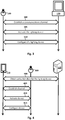
- the PoS terminal 120 and the lighting device 100 establish 300 a communications channel whereby they can communicate with one another securely. This is done in a conventional manner, e.g. via an exchange of messages between the PoS terminal 120 and the lighting device 100, which will be readily understood by those skilled in the art without further explanation.
- the exchange may be via Near Field Communication, for example.
- the PoS terminal 120 establishes that it is authorized to activate the lighting device 100, using the information it obtained in the preliminary step mentioned above.
- the PoS terminal 120 configures 310 the lighting device 100. For example, at the store the customer may select one or more desired parameters for the lighting device 100, such as a desired hue, a desired saturation or a desired color temperature.
- the PoS terminal 120 may be capable of configuring the lighting device 100 in accordance with the one or more desired parameters of the customer.
- the PoS terminal 120 configures 310 the lighting device 100 by sending thereto one or more messages indicative of one or more desired parameters of the lighting device 100.
- the one or more messages may be transmitted over the secure communications channel, or 'in the clear'.
- a purchaser who has purchased the lighting device 100 may activate it at home via the Internet 105.
- the purchaser may use his or her wireless communications device 110 for performing the activation.
- the wireless communications device 110 may obtain sufficient information to be able to communicate with a server 115 associated with the lighting device 100.
- the wireless communications device 110 may, via an integrated camera thereof, capture and decode a QR code displayed on the lighting device 100 and/or its packaging.
- the decoded QR code may comprise a logical address of the server 115, e.g. a uniform resource identifier (URI), a MAC address and/or an IP address.
- the wireless communications device 110 is then operable to communicate with the server 115 and thereby obtain activation data for the lighting device 100; obtaining the activation data for the lighting device 100 may require proof-of-purchase details to be supplied to the server 115, e.g. a number, password etc. provided to the purchaser at the time of purchase of the lighting device 100.
- the wireless communications device 110 is operable to activate and optionally configure the lighting device 100.
- the purchaser may place the lighting device 100 in a socket of a lighting fixture for which it was purchased, wherefrom it will receive the electrical power it needs for operation.
- the lighting device 100 is in a suitable condition to be activated and optionally configured by the wireless communications device 110.
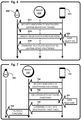
- the wireless communications device 110 and the lighting device 100 are configured to establish 405 a communications channel whereby they can communicate with one another securely. This may be initiated by the wireless communications device 110; it may be done in a conventional manner, e.g. via an exchange of messages between the wireless communications device 110 and the lighting device 100, which will be readily understood by those skilled in the art without further explanation.
- the exchange may be via wireless communication, e.g. via a Zigbee Light Link.
- the wireless communications device 110 establishes that it is authorized to activate the lighting device 100, e.g. using known techniques with the activation data it obtained 400 from the server 115.
- the wireless communications device 110 activates 410 the lighting device 100, thereby causing the lighting device 100 to transition to an operative state from an inoperative state or a functionally-limited state. To do so, the wireless communications device 110 sends an activation to the lighting device 100 over the secure communications channel in a conventional manner, which may involve uni- or bi-directional transmission of message(s).
- the activation is an encoded command which the lighting device 100 is configured to recognize and decode. The activation, once decoded, is what causes the lighting device 100 to transition to the operative state.
- the wireless communications device 110 configures 415 the lighting device 100.
- the wireless communications device 110 may display on a screen thereof a user interface for the customer to select one or more desired parameters for the lighting device 100, such as a desired hue, a desired saturation or a desired color temperature.
- the wireless communications device 110 may be capable of configuring the lighting device 100 in accordance with the one or more desired parameters of the customer, as indicated via the user interface.
- the wireless communications device 110 configures 415 the lighting device 100 by sending thereto one or more messages indicative of one or more desired parameters of the lighting device 100. The one or more messages may be transmitted over the secure communications channel, or 'in the clear'.
- a purchaser who has purchased the lighting device 100 may activate it at home via the Internet 105.
- the purchaser may use his or her wireless communications device 110 for performing the activation.
- a lighting device 100 is activated, and optionally configured, over the Internet by a server.
- the wireless communications device 110 may obtain sufficient information to be able to communicate with a server 115 associated with the lighting device 100.
- the wireless communications device 110 may, via an integrated camera thereof, capture and decode a QR code displayed on the lighting device 100 and/or its packaging.
- the decoded QR code may comprise a logical address of the server 115, e.g. a uniform resource identifier (URI), a MAC address and/or an IP address.
- the wireless communications device 110 is then operable to communicate with, and thereby send proof-of-purchase details to, the server 115.
- the proof-of-purchase details may comprise, e.g., a number, password etc. provided to the purchaser at the time of purchase of the lighting device 100.
- the purchaser may need to manually enter the proof-of-purchase details into wireless communications device 110 via a suitable user interface thereof.
- the purchaser may place the lighting device 100 in a socket of a lighting fixture for which it was purchased, wherefrom it will receive the electrical power it needs for operation.
- the lighting device 100 is in a suitable condition to be activated and optionally configured by the server 115.
- the server 115 activates 510 the lighting device 100, thereby causing the lighting device 100 to transition to an operative state from an inoperative state or a functionally-limited state. To do so, the server 115 sends an activation to the lighting device 100 over the secure communications channel in a conventional manner, which may involve uni- or bi-directional transmission of message(s).
- the activation is an encoded command which the lighting device 100 is configured to recognize and decode. The activation, once decoded, is what causes the lighting device 100 to transition to the operative state.
- the server 115 configures 515 the lighting device 100.
- the server 115 may be capable of configuring the lighting device 100 in accordance with the one or more desired parameters of the customer, as provided to the server 115 during the preliminary step described above.
- the server 115 configures 515 the lighting device 100 by sending thereto one or more messages indicative of one or more desired parameters of the lighting device 100.
- the one or more messages may be transmitted over the secure communications channel, or 'in the clear'.
- the PoS terminal 120 obtains an identifier thereof and communicates it, along with an associated PoS "sale confirmed" message, to a remote database.
- the communications device 110 need not provide proof-of-purchase details to the server 115, and the user need not manually enter the proof-of-purchase details into wireless communications device 110 via a suitable user interface thereof.
- the lighting device may be configured to receive the activation, e.g. automatically after it is installed in a socket for use, from a remote server or from a nearby lighting device.
- Suitable instructions for the methods herein may be stored/distributed on a suitable computer readable medium, such as an optical storage medium or a solid-state medium supplied together with or as part of other hardware, but may also be distributed via other computer program products such as Internet/intranet downloads or via other wired or wireless communication.
- a suitable computer readable medium such as an optical storage medium or a solid-state medium supplied together with or as part of other hardware, but may also be distributed via other computer program products such as Internet/intranet downloads or via other wired or wireless communication.
- lighting devices may be configured to activate otherwise deactivated lighting device functions in response to various events and/or stimuli involving other lighting devices, lighting system bridges and/or mobile computing devices such as smart phones and/or tablet computers.
- a lighting device 600 configured with selected aspects of the present disclosure may be part of a lighting system (not depicted) under the control of a lighting system bridge 650.
- a wireless communication device 610 also referred to as "mobile computing device 610,” may be in communication with lighting system bridge 650 and/or lighting device 600 over one or more networks (not depicted in Fig. 6 , see network(s) 105 in Fig. 1 ).
- lighting device 600 may provide, e.g., directly or through bridge 650, an indication of its deactivated lighting device functions.
- lighting device 600 may provide, in various formats, a list of lighting characteristics it is capable of emitting, a list of lighting scenes it has at its disposal, a list of dynamic lighting sequences it is capable of emitting, a baby monitoring function, and so forth.
- mobile computing device 610 may render, e.g., on a touch screen, a user interface that presents to a user a graphical representation (e.g., pull down menu, list, etc.) of deactivated lighting device functions of lighting device 600.
- a user may select one or more of the deactivated lighting devices to be activated.
- the user may be provided with the option to purchase activation of one or more lighting device functions, e.g., using a credit card or online bank account, or indirectly, by means of a user account that is coupled to a credit card or online bank account.
- the user interface may be operable by the user to select a time interval for which the deactivated lighting device function will be activated. For example, the more the user spends, the longer the function will be activated.
- mobile computing device 610 may transmit to lighting device, directly or via bridge 650, a command to activate one or more user-selected deactivated lighting device functions. If the user designated a particular time interval for the lighting device function to be activated, then the command may include commands to first activate the deactivated lighting device function of lighting device 600, and then to deactivate the lighting device function after passage of the time interval. In some embodiments, the lighting device function may be deactivated after the predetermined time interval unless a lighting device function renewal communication is received, e.g., from bridge 650 or mobile computing device 610, during the time interval.
- Fig. 7 depicts a slight variation of the scenario demonstrated by Fig. 6 .
- a lighting device 700 configured with selected aspects of the present disclosure is in communication with a lighting system bridge 750 and a mobile computing device 710 over one or more networks (not depicted).
- Many of the operations in Fig. 7 are similar to those in Fig. 6 , except that instead of obtaining information about deactivated functions from lighting device 700 itself, mobile computing device 710 interacts with bridge 750.
- mobile computing device 710 may request, e.g., from lighting system bridge 760, an indication of one or more deactivated lighting device functions of lighting device 600.
- lighting system bridge 750 may maintain a database (not depicted) of lighting devices under its control, as well as lighting device functions (activated and deactivated) of those lighting devices.
- lighting system bridge 750 may not maintain such a database, or at least as complete a database, and may instead inquire with lighting devices (e.g., 700) on the fly about their functionality when requested by a mobile computing device.
- one or more deactivated lighting device functions may be activated based on a composition of a lighting system.
- a first lighting device 800a configured with selected aspects of the present disclosure is being added to a lighting system controlled by a bridge 850.
- the lighting system already includes one or more lighting devices, including second lighting device 800b.
- lighting system bridge 850 is in communication with a database 851 of one or more lighting device records associated with one or more lighting devices of the lighting system.
- a lighting device record may exist for each lighting device that is associated with a lighting system.
- Each lighting device record may include various information about a lighting device, including but not limited to an identifier (e.g., serial number, model number, etc.), an identity of a manufacturer or other entity that makes, sells, distributes and/or markets the lighting device, one or more characteristics of the lighting device (e.g., lumen output, size, shape, power requirements, etc.), an amount paid for the lighting device, and so forth.
- a lighting device record may include information about one or more lighting device functions that the lighting device is capable of performing.
- Various criteria may be used when determining whether a composition of a lighting system warrants activation or deactivation of one or more lighting device functions of one or more lighting devices. These criteria may include but are not limited to a threshold number of lighting devices being present in the lighting system, a threshold number of lighting devices associated with a particular entity (e.g., manufacturer, distributor retailer, etc.) being present in the lighting system, a threshold number of lighting devices having a particular lighting device function (e.g., capability of emitting various colors or sequences of colors, etc.) activated that are present in the lighting system, a threshold amount of money having been spent on lighting devices from a particular entity, and so forth.
- a threshold number of lighting devices being present in the lighting system
- a threshold number of lighting devices associated with a particular entity e.g., manufacturer, distributor retailer, etc.
- a threshold number of lighting devices having a particular lighting device function e.g., capability of emitting various colors or sequences of colors, etc.
- Such functionality may be used, for instance, by manufacturers, retailers or other entities to reward customers for purchasing their products. Assume a user adds greater than a predetermined number of lighting devices sold by a particular retailer to his or her lighting system.
- a component of the light system such as bridge 850, may determine that the composition of the lighting system satisfies a predetermined threshold of lighting devices from that retailer. Then, as shown in Fig. 8 , a component of the lighting system, such as lighting system bridge 850, may transmit a command to one or more lighting devices (such as second lighting device 800b) at 878 to activate a particular lighting device function.
- the more lighting devices that user purchases from that retailer and installs in her lighting system
- the more lighting device functions are "unlocked" (i.e., activated).
- lighting devices may make such a determination. For instance, when a new lighting device is added, existing lighting devices may ascertain a composition of the lighting system, e.g., based on information stored in database 851. Each of those individual lighting devices may then make its own determination of whether the predetermined criterion is satisfied, and may activate one or more of its own lighting device functions accordingly.
- a user may operate mobile computing device 910 to select one or more lighting device functions of lighting device 900 or another lighting device in the lighting system to activate (or deactivate).
- mobile computing device 910 may transmit a command to lighting device 900 (or to another lighting device, or to lighting system bridge 950) to activate one or more deactivated lighting device functions.
- function-specific lighting devices may communicate their lighting device functions directly to other lighting devices (or indirectly through a lighting system bridge), e.g., upon joining a lighting system.
- Other lighting devices with similar lighting device functions that perhaps are deactivated may, in response, activate those deactivated functions.
- a first lighting device 1000a that is marketed to perform a particular lighting device function is being added to a lighting system.
- first lighting device 1000a may transmit an indication of that marketed lighting device function to a second lighting device 1000b that is already associated with the lighting system.
- Second lighting device 1000b may then activate its own same or similar lighting device function.
- first lighting device 1000a may transmit an indication of the marketed lighting device function it is capable of performing to a third lighting device 1000c associated with the lighting system.
- Third lighting device 1000c may respond similarly to second lighting device 1000b assuming third lighting device 1000c has the same or similar built in lighting device functionality. If a lighting device associated with a lighting system does not include the same or similar functionality, it may simply ignore the communication from first lighting device 1000a. Note that while 1092 and 1094 are depicted occurring one after the other, they may also occur simultaneously.
- first lighting device 1000a may simply broadcast an indication of one or more lighting device functions it is capable of performing. In this manner, a user may activate a particular lighting device function at multiple lighting devices of a lighting system by purchasing another lighting device that has the desired lighting device function activated, and adding it to the lighting system.
- a mobile computing device e.g., 110, 610, 710, 910 may be used concurrently by a user to indicate which lighting devices on which the desired lighting device function should be activated. Additionally, in some embodiments, the newly added lighting device 1000a may activate its own deactivated lighting device functions based on those that are already activated on already-installed lighting devices (e.g., 1000b, 1000c) of the lighting system.
- activation/deactivation of a lighting device function may depend on one or more network characteristics of a lighting device.
- a lighting device may have domain restrictions that prevent the lighting device from being used to activate functions in multiple domains (e.g., businesses, homes, etc.).
- a function trial identifier may be valid, and a corresponding lighting device function may remain activated, only as long as the lighting device resides in the same domain as where the lighting device function was activated originally.
- Such a domain may be identified by a network prefix, a specific network device (e.g., lighting system bridge), and so forth.
- a composition of a lighting system may change, which may prompt deactivation of one or more lighting device functions.
- a lighting device may be configured to deactivate one or more lighting device functions upon determination that a composition of a lighting system with which the lighting device is associated no longer satisfies a predetermined criterion.
- the asymmetric key pair may be used to verify a signature, whereby a certificate is the "information" that unlocks the additional functionality and it is signed by a signature.
- the private key may be used by the service provider to create a signature that may be used to sign the certificate to activate one or more deactivated lighting device functions.
- the lighting device may check the signature (e.g., using a public key) on the certificate to verify that the signature was provided by a particular entity.
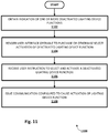
- one or more deactivated lighting device functions may be recommended to a user in various ways. For instance, a mobile computing device or lighting system bridge may determine a composition of a lighting system. It may then determine whether the composition satisfies one or more predetermined criteria. If the answer is yes, then the mobile computing device may recommend (e.g., by rendering a message on a touch screen display) one or more lighting device functions to a user, e.g., for purchase or for temporary use as a trial.
- a mobile computing device or lighting system bridge may determine a composition of a lighting system. It may then determine whether the composition satisfies one or more predetermined criteria. If the answer is yes, then the mobile computing device may recommend (e.g., by rendering a message on a touch screen display) one or more lighting device functions to a user, e.g., for purchase or for temporary use as a trial.
- the mobile computing device may render a user interface that is operable to purchase or otherwise select one or more lighting device functions for activation.
- the mobile computing device may render a drop down menu that includes a list of the deactivated functions obtained at block 1102.
- the mobile computing device may receive the user's selection of one or more of those lighting device functions for activation, in exchange for money or otherwise.
- the mobile computing device may issue a communication, e.g., directly to a lighting device or to a lighting system bridge, to cause activation of the user-selected lighting device function.
Description
- The present application claims priority to
European Patent Application No. 13162549.3, filed April 5, 2013 - The present invention relates to lighting, particularly to activatable lighting devices, to lighting fixtures comprising such lighting devices and to systems and methods for configuring such lighting devices.
- Digital lighting technologies, i.e., illumination based on semiconductor light sources, such as light-emitting diodes (LEDs), offer a viable alternative to traditional fluorescent, HID, and incandescent lamps. Functional advantages and benefits of LEDs include high energy conversion and optical efficiency, durability, lower operating costs, and many others. Recent advances in LED technology have provided efficient and robust full-spectrum lighting sources that enable a variety of lighting effects in many applications. Some of the fixtures embodying these sources feature a lighting module, including one or more LEDs capable of producing different colors, e.g., red, green, and blue, as well as a processor for independently controlling the output of the LEDs in order to generate a variety of colors and color-changing lighting effects, for example, as discussed in detail in
U.S. Patent Nos. 6,016,038 and6,211,626 . - Retail outlets may stock a number of different color temperature variants of LED lamps, and each of the color temperature variants may be offered in a number of different power ratings. Stocking each of the available color temperature variants in each of the power ratings would entail significant inventory cost, and would complicate and reduce the efficiency of the associated supply chain. This is less of an issue for configurable LED lamps whose color temperature can be configured after purchase, e.g. as disclosed in patent publication no.
WO 2011/033409 A1 , since obviously such lamps do not have different color temperature variants. However, such configurable LED lamps have a higher purchase price than the non-configurable LED lamps.US 2011/0199004 A1 discloses a manual commissioning of a lighting system wherein a user can be provided with a pointing device capable of emitting or returning a signal which can be received by detectors co-located with each fixture in the lighting system. The user can add a fixture to a group by aiming the pointing device at the fixture when the fixture is not assigned to the group, and the user can remove a fixture from a group in the same way when the fixture was previously assigned to the group. Additional user gestures are also disclosed. - Today's LED lamps, particularly configurable LED lamps, are expensive compared with their traditional counterparts. Therefore LED lamps are unaffordable for some potential users, such as potential users in developing countries. Furthermore, the small size and relatively high purchase price of LED lamps, particularly the configurable LED lamps, makes them attractive to shop-lifters.
- Disclosed herein are various aspects and embodiments which address at least one of the shortcomings noted above. The invention is defined by the lighting device according to independent claim 1 and to computer implemented methods according to independent claims 9 and 10. Preferred embodiments of the invention are defined by the dependent claims.
- Generally, in one aspect, a computing device may include one or more processors, a communication interface coupled with the one or more processors, and memory. The memory may store instructions that, in response to execution of the instructions by the one or more processors, cause the one or more processors to: ascertain, based at least in part on a database of one or more lighting device records associated with one or more lighting devices of a lighting system, a composition of the lighting system; determine, based on the ascertained composition, that a predetermined criterion is satisfied; and issue, via the communication interface in response to the determination, a communication configured to facilitate activation of a deactivated lighting device function of a lighting device associated with the lighting system.
- In various embodiments, the predetermined criterion comprises a threshold number of lighting devices present in the lighting system. In various embodiments, the predetermined criterion comprises a threshold number of lighting devices associated with a particular entity present in the lighting system. In various embodiments, the predetermined criterion comprises a threshold number of lighting devices having a particular lighting device function activated that are present in the lighting system. In various embodiments, the particular lighting device function comprises a baby monitoring function, a security monitoring function, a user-input detecting function, an intercom function, a Wi-Fi repeater function, a wake up light effect function, a nightlight function, an info-light function, an environmental parameter-sensing function, an audio rendering or recording function, or a speech recognition function.
- In various embodiments, the memory further stores the database of one or more lighting device records. In various embodiments, the memory further stores instructions that, in response to execution of the instructions by the one or more processors, cause the one or more processors to transmit the communication to a remote computing device, and wherein the communication facilitates user operation of the remote computing device to activate the deactivated lighting device function. In various versions, the remote computing device comprises a mobile computing device, and the communication is configured to cause the mobile computing device to render a user interface operable by a user to activate the deactivated lighting device function. In various versions, the remote computing device may be a lighting system bridge that controls the lighting system or a lighting device associated with the lighting system.
- In various embodiments, the memory further stores instructions that, in response to execution of the instructions by the one or more processors, cause the one or more processors to transmit the communication to the lighting device associated with the lighting system or a lighting system bridge that controls the lighting system, and wherein the communication comprises a command to activate the deactivated lighting device function. In various versions, the memory further stores instructions that, in response to execution of the instructions by the one or more processors, cause the one or more processors to render a user interface operable by a user to purchase activation of the deactivated lighting device function of the lighting device. In various versions, the memory further stores instructions that, in response to execution of the instructions by the one or more processors, cause the one or more processors to update the database to reflect activation of the deactivated lighting device function.
- In another aspect, a computer-implemented method may include: obtaining, by a mobile computing device via a wireless communication interface, an indication of one or more deactivated lighting device functions of a lighting device; receiving, by the mobile computing device via a user interface of the mobile computing device, a user instruction to select and activate a deactivated lighting device function of the lighting device; and issuing, by the mobile computing device via the wireless communication interface, a communication configured to cause activation of the deactivated lighting device function of the lighting device.
- In various embodiments, the issuing comprises transmitting, by the mobile computing device to the lighting device or a lighting system bridge in communication with the lighting device, a command to activate the deactivated lighting device function of the lighting device. In various embodiments, the method further includes rendering, on a touch screen of the mobile computing device, a user interface operable by a user to purchase activation of the deactivated lighting device function of the lighting device. In various versions, the user interface is further operable by the user to select a time interval for which the deactivated lighting device function will be activated. In some embodiments, the issuing may include transmitting, by the mobile computing device to the lighting device or a lighting system bridge in communication with the lighting device, commands to activate the deactivated lighting device function of the lighting device and then deactivate the lighting device function after passage of the time interval.
- In various embodiments, obtaining the indication of one or more deactivated lighting device functions of the lighting device comprises receiving, by the mobile computing device directly from the lighting device, the indication of one or more deactivated lighting device functions of the lighting device. In various embodiments, obtaining the indication of one or more deactivated lighting device functions of the lighting device comprises obtaining, by the mobile computing device from a lighting system bridge in communication with the lighting device, the indication of one or more deactivated lighting device functions of the lighting device.
- In various embodiments, obtaining the indication of one or more deactivated lighting device functions of the lighting device comprises obtaining, from a database of one or more lighting device records associated with one or more lighting devices of a lighting system, a composition of the lighting system. In various versions, the database is stored in memory of the mobile computing device.
- In another aspect, a lighting device may include: one or more LED-based light sources; a communication interface; and a controller operably coupled with the one or more LED-based light sources and the communication interface. The controller may be configured to: ascertain, based at least in part on a database of one or more lighting device records associated with one or more lighting devices of a lighting system with which the lighting device is associated, a composition of the lighting system; determine, based on the ascertained composition, that a predetermined criterion is satisfied; and activate a deactivated lighting device function of the lighting device in response to the determination.
- In various embodiments, the controller is further configured to provide, to another lighting device via the communication interface, a command to activate the same deactivated lighting device function on the another lighting device. In various embodiments, the controller is further configured to deactivate the lighting device function after a predetermined time interval. In various embodiments, the controller is further configured to deactivate the lighting device function after a predetermined time interval unless a lighting device function renewal communication is received via the communication interface during the time interval.
- In various embodiments, the controller is further configured to deactivate the lighting device function upon determination that a network characteristic of the lighting device has been altered. In various embodiments, the controller is further configured to deactivate the lighting device function upon determination that the composition of the lighting system no longer satisfies the predetermined criterion. In various embodiments, the controller is further configured to deactivate the lighting device function upon determination that a state of a dongle has been altered.
- In various embodiments, the controller is further configured to: provide, to a computing device via the communication interface, an indication of one or more deactivated lighting device functions of the lighting device; receive, via the communication interface, a command to activate the deactivated lighting device function; and activate the deactivated lighting device function in response to the command.
- As used herein for purposes of the present disclosure, the term "LED" should be understood to include any electroluminescent diode or other type of carrier injection/junction-based system that is capable of generating radiation in response to an electric signal. Thus, the term LED includes, but is not limited to, various semiconductor-based structures that emit light in response to current, light emitting polymers, organic light emitting diodes (OLEDs), electroluminescent strips, and the like. In particular, the term LED refers to light emitting diodes of all types (including semi-conductor and organic light emitting diodes) that may be configured to generate radiation in one or more of the infrared spectrum, ultraviolet spectrum, and various portions of the visible spectrum (generally including radiation wavelengths from approximately 400 nanometers to approximately 700 nanometers). Some examples of LEDs include, but are not limited to, various types of infrared LEDs, ultraviolet LEDs, red LEDs, blue LEDs, green LEDs, yellow LEDs, amber LEDs, orange LEDs, and white LEDs (discussed further below). It also should be appreciated that LEDs may be configured and/or controlled to generate radiation having various bandwidths (e.g., full widths at half maximum, or FWHM) for a given spectrum (e.g., narrow bandwidth, broad bandwidth), and a variety of dominant wavelengths within a given general color categorization.
- For example, one implementation of an LED configured to generate essentially white light (e.g., a white LED) may include a number of dies which respectively emit different spectra of electroluminescence that, in combination, mix to form essentially white light. In another implementation, a white light LED may be associated with a phosphor material that converts electroluminescence having a first spectrum to a different second spectrum. In one example of this implementation, electroluminescence having a relatively short wavelength and narrow bandwidth spectrum "pumps" the phosphor material, which in turn radiates longer wavelength radiation having a somewhat broader spectrum.
- It should also be understood that the term LED does not limit the physical and/or electrical package type of an LED. For example, as discussed above, an LED may refer to a single light emitting device having multiple dies that are configured to respectively emit different spectra of radiation (e.g., that may or may not be individually controllable). Also, an LED may be associated with a phosphor that is considered as an integral part of the LED (e.g., some types of white LEDs). In general, the term LED may refer to packaged LEDs, non-packaged LEDs, surface mount LEDs, chip-on-board LEDs, T-package mount LEDs, radial package LEDs, power package LEDs, LEDs including some type of encasement and/or optical element (e.g., a diffusing lens), etc.
- The term "light source" should be understood to refer to any one or more of a variety of radiation sources, including, but not limited to, LED-based sources (including one or more LEDs as defined above), incandescent sources (e.g., filament lamps, halogen lamps), fluorescent sources, phosphorescent sources, high-intensity discharge sources (e.g., sodium vapor, mercury vapor, and metal halide lamps), lasers, other types of electroluminescent sources, pyro-luminescent sources (e.g., flames), candle-luminescent sources (e.g., gas mantles, carbon arc radiation sources), photo-luminescent sources (e.g., gaseous discharge sources), cathode luminescent sources using electronic satiation, galvano-luminescent sources, crystallo-luminescent sources, kine-luminescent sources, thermo-luminescent sources, triboluminescent sources, sonoluminescent sources, radioluminescent sources, and luminescent polymers.
- A given light source may be configured to generate electromagnetic radiation within the visible spectrum, outside the visible spectrum, or a combination of both. Hence, the terms "light" and "radiation" are used interchangeably herein. Additionally, a light source may include as an integral component one or more filters (e.g., color filters), lenses, or other optical components. Also, it should be understood that light sources may be configured for a variety of applications, including, but not limited to, indication, display, and/or illumination. An "illumination source" is a light source that is particularly configured to generate radiation having a sufficient intensity to effectively illuminate an interior or exterior space. In this context, "sufficient intensity" refers to sufficient radiant power in the visible spectrum generated in the space or environment (the unit "lumens" often is employed to represent the total light output from a light source in all directions, in terms of radiant power or "luminous flux") to provide ambient illumination (i.e., light that may be perceived indirectly and that may be, for example, reflected off of one or more of a variety of intervening surfaces before being perceived in whole or in part).
- The term "spectrum" should be understood to refer to any one or more frequencies (or wavelengths) of radiation produced by one or more light sources. Accordingly, the term "spectrum" refers to frequencies (or wavelengths) not only in the visible range, but also frequencies (or wavelengths) in the infrared, ultraviolet, and other areas of the overall electromagnetic spectrum. Also, a given spectrum may have a relatively narrow bandwidth (e.g., a FWHM having essentially few frequency or wavelength components) or a relatively wide bandwidth (several frequency or wavelength components having various relative strengths). It should also be appreciated that a given spectrum may be the result of a mixing of two or more other spectra (e.g., mixing radiation respectively emitted from multiple light sources).
- For purposes of this disclosure, the term "color" is used interchangeably with the term "spectrum." However, the term "color" generally is used to refer primarily to a property of radiation that is perceivable by an observer (although this usage is not intended to limit the scope of this term). Accordingly, the terms "different colors" implicitly refer to multiple spectra having different wavelength components and/or bandwidths. It also should be appreciated that the term "color" may be used in connection with both white and non-white light.
- The term "color temperature" generally is used herein in connection with white light, although this usage is not intended to limit the scope of this term. Color temperature essentially refers to a particular color content or shade (e.g., reddish, bluish) of white light. The color temperature of a given radiation sample conventionally is characterized according to the temperature in degrees Kelvin (K) of a black body radiator that radiates essentially the same spectrum as the radiation sample in question. Black body radiator color temperatures generally fall within a range of approximately 700 degrees K (typically considered the first visible to the human eye) to over 10,000 degrees K; white light generally is perceived at color temperatures above 1500-2000 degrees K.
- Lower color temperatures generally indicate white light having a more significant red component or a "warmer feel," while higher color temperatures generally indicate white light having a more significant blue component or a "cooler feel." By way of example, fire has a color temperature of approximately 1,800 degrees K, a conventional incandescent bulb has a color temperature of approximately 2848 degrees K, early morning daylight has a color temperature of approximately 3,000 degrees K, and overcast midday skies have a color temperature of approximately 10,000 degrees K. A color image viewed under white light having a color temperature of approximately 3,000 degree K has a relatively reddish tone, whereas the same color image viewed under white light having a color temperature of approximately 10,000 degrees K has a relatively bluish tone.
- The term "lighting fixture" is used herein to refer to an implementation or arrangement of one or more lighting units in a particular form factor, assembly, or package. The term "lighting unit" is used herein to refer to an apparatus including one or more light sources of same or different types. A given lighting unit may have any one of a variety of mounting arrangements for the light source(s), enclosure/housing arrangements and shapes, and/or electrical and mechanical connection configurations. Additionally, a given lighting unit optionally may be associated with (e.g., include, be coupled to and/or packaged together with) various other components (e.g., control circuitry) relating to the operation of the light source(s). An "LED-based lighting unit" refers to a lighting unit that includes one or more LED-based light sources as discussed above, alone or in combination with other non LED-based light sources. A "multi-channel" lighting unit refers to an LED-based or non LED-based lighting unit that includes at least two light sources configured to respectively generate different spectrums of radiation, wherein each different source spectrum may be referred to as a "channel" of the multi-channel lighting unit.
- The term "lighting device" is used herein to refer generally to a lighting unit and/or lighting fixture (e.g., a luminaire) that includes one or more light sources of same or different types. A given lighting device may have any one or more of a variety of mounting arrangements for the light source(s), enclosure/housing arrangements and shapes, optics, power-supply circuitry, control circuitry and/or electrical and mechanical connection configurations. A LED lamp, e.g. the "Philips Hue" lamp, is one example of such a lighting device.
- The term "controller" is used herein generally to describe various apparatus relating to the operation of one or more light sources. A controller can be implemented in numerous ways (e.g., such as with dedicated hardware) to perform various operations discussed herein. A "processor" is one example of a controller which employs one or more microprocessors that may be programmed using software (e.g., microcode) to perform various operations discussed herein. A controller may be implemented with or without employing a processor, and also may be implemented as a combination of dedicated hardware to perform some operations and a processor (e.g., one or more programmed microprocessors and associated circuitry) to perform other operations. Examples of controller components that may be employed in various embodiments of the present disclosure include, but are not limited to, conventional microprocessors, application specific integrated circuits (ASICs), and field-programmable gate arrays (FPGAs).
- In various implementations, a processor or controller may be associated with one or more storage media (generically referred to herein as "memory," e.g., volatile and non-volatile computer memory such as RAM, PROM, EPROM, and EEPROM, floppy disks, compact disks, optical disks, magnetic tape, etc.). In some implementations, the storage media may be encoded with one or more programs that, when executed on one or more processors and/or controllers, perform at least some of the operations discussed herein. Various storage media may be fixed within a processor or controller or may be transportable, such that the one or more programs stored thereon can be loaded into a processor or controller so as to implement various aspects of the present invention discussed herein. The terms "program" or "computer program" are used herein in a generic sense to refer to any type of computer code (e.g., software or microcode) that can be employed to program one or more processors or controllers.
- The term "user interface" as used herein refers to an interface between a human user or operator and one or more devices that enables communication between the user and the device(s). Examples of user interfaces that may be employed in various implementations of the present disclosure include, but are not limited to, switches, potentiometers, buttons, dials, sliders, a mouse, keyboard, keypad, various types of game controllers (e.g., joysticks), track balls, display screens, various types of graphical user interfaces (GUIs), touch screens, microphones and other types of sensors that may receive some form of human-generated stimulus and generate a signal in response thereto.
- The term "lighting device function" as used herein refers to any routine or state machine performed by a lighting device, by a lighting unit installed in a lighting fixture, or by a lighting fixture. Lighting device functions may include but are not limited to emitting predetermined lighting scenes, performing a baby monitor function, emitting light in response to detection of motion, becoming touch-, sound- or motion-sensitive, emitting light having various characteristics (e.g., hue, saturation, color temperature, coded light, various brightness levels, aesthetically pleasing transitions between lighting effects, etc.), performing as a Wi-Fi repeater, acting as an intercom, and so forth. Other lighting device functions may include but are not limited to a security monitoring function, a wake up light effect function, a nightlight function, an info-light function, a user input detection function (e.g., touch, sound, etc.), an environmental parameter-sensing function (e.g., light, temperature, humidity, barometric pressure, noise, etc.), an audio rendering and/or recording function, a speech recognition function, and so forth.
- A lighting device function may include emission of a dynamic lighting sequence as well. For instance, a presence-simulating lighting device function may include emission of a predetermined lighting sequence to give the impression that someone is home (e.g., by emitting light to simulating someone walking around or even emitting light to mimic a television). A "deactivated" lighting state function may refer to a lighting function that is built into a lighting device, but that is not performable until activated. A deactivated lighting function may be "activated" in response to various events and stimuli, as will be discussed herein.
- It should be appreciated that all combinations of the foregoing concepts and additional concepts discussed in greater detail below (provided such concepts are not mutually inconsistent) are contemplated as being part of the inventive subject matter disclosed herein. In particular, all combinations of claimed subject matter appearing at the end of this disclosure are contemplated as being part of the inventive subject matter disclosed herein.
- In the drawings, like reference characters generally refer to the same parts throughout the different views. Also, the drawings are not necessarily to scale, emphasis instead generally being placed upon illustrating the principles of the invention.
-
Fig. 1 schematically shows a system for activating a device for illuminating an environment. -
Fig. 2 schematically shows some of the main components of the device ofFigure 1 . -
Fig. 3 illustrates the communication between a point of sale terminal and the device ofFigures 1 and 2 . -
Fig. 4 illustrates the communication between a wireless communications device, a server and the device ofFigures 1 and 2 . -
Fig. 5 illustrates the communication between a wireless communications device, a server and the device ofFigures 1 and 2 . -
Figs. 6-10 illustrate various communications that may occur between lighting devices configured with selected aspects of the present disclosure and various other components. -
Fig. 11 depicts an example method that may be implemented by a lighting device. - As shown in
Figure 1 , in an embodiment alighting device 100 is communicatively connected to one ormore networks 105. Also connected to the network(s) 105 are: awireless communications device 110, such as a smartphone or a tablet computer; one ormore servers 115; and a point of sale (PoS)terminal 120. The respective connections between these devices and the network(s) 105 may, for example, be one or more of Zigbee Light Link connections, Bluetooth connections, WiFi connections, wired Ethernet connections, power line communication connections and the like. Each of thedevices - As shown in
Figure 2 , in an embodiment thelighting device 100 comprises one or morelight sources 205, an input for receiving power (hereinafter, the "power input 210") and acontroller 215. Thecontroller 215 is coupled to thepower input 210 and to the light source(s) 205. - The light source(s) 205 may comprise any one or more of a variety of radiation sources, including, but not limited to, LED-based sources, incandescent sources (e.g., filament lamps, halogen lamps), fluorescent sources, phosphorescent sources, high-intensity discharge sources (e.g., sodium vapor, mercury vapor, and metal halide lamps), lasers, or other types of electroluminescent light sources.
- The
power input 210 may comprise any one or more of a variety of suitable (known) connectors, such as conventional lamp connectors like an Edison screw base, a bayonet-style base, a bi-pin connector (or the like), a connector for power-over-Ethernet, or any other suitable connector. - As shown in
Figure 2 , thecontroller 215 comprises a communication interface in the form of areceiver 220 for receiving an activation (explained below) from outside thelighting device 100. Thereceiver 220 may comprise an antenna and associated circuitry for receiving and decoding WiFi signals, Bluetooth signals, Zigbee Lightlink signals or the like. Additionally or alternatively, thereceiver 220 may comprise a connector and associated circuitry for receiving and decoding signals by wire, e.g. via an Ethernet cable, a USB cable or the like. - The
controller 215 further comprises apower supply unit 225, which is connected to and receives power from thepower input 210. Thepower supply unit 225 is arranged to generate, under the control of thecontroller 215, drive signals for thecontroller 215 to drive the light source(s) 205. - In overview, the
controller 215 is configured to maintain thelighting device 100 in an inoperative state or in a functionally-limited state until an activation is received. In response to receiving the activation, thecontroller 215 will transition thelighting device 100 into an operative state in which thecontroller 215 drives the light source(s) 205 according to one or more preset parameters and/or according to one or more user-selected parameters. Methods of activating thelighting device 100 will be explained below with reference toFigures 3 and 4 . - As shown in
Figure 3 , in some embodiments thelighting device 100 is activated at thePoS terminal 120. For example, a customer may purchase thelighting device 100 at a shop via thePoS terminal 120. Once the purchase has been completed, thePoS terminal 120 activates and optionally configures thelighting device 100. - As a preliminary step, the
PoS terminal 120 obtains (e.g. from memory or via communication with another device or apparatus) information for activating thelighting device 100. In order to obtain the information, thePoS terminal 120 may be configured to decoded a QR code on thelighting device 100 or its packaging, and to obtain therefrom a memory address, logical address (e.g. a uniform resource identifier (URI), a MAC address and/or an IP address) or the like which indicates where the information can be obtained from. - In this embodiment, the
lighting device 100 is connected to a suitable socket (not shown) of thePoS terminal 120 whereby the PoS terminal 120 powers thelighting device 100 temporarily so that it can activate thelighting device 100. In other embodiments, thePoS terminal 120 may temporarily power thelighting device 100 via inductive coupling and/or capacitive coupling, so thelighting device 100 may remain entirely enclosed in its packaging during activation. The coupling may suffice to power thecontroller 215, but not necessarily to a sufficient level to enable thepower supply unit 225 to drive the light source(s) 205. For instance, in various embodiments (not shown) thecontroller 215 may comprise a microcontroller and non-volatile memory, both connected to circuitry for receiving electrical power via an inductive and/or capacitive coupling to thePoS terminal 120; the coupling circuitry does not supply electrical power thepower supply unit 225. Thus the activation may be performed via the microcontroller and non-volatile memory, using less power than thepower supply unit 225 would require in order to drive the light source(s) 205. - In order to activate the
lighting device 100, thePoS terminal 120 and thelighting device 100 establish 300 a communications channel whereby they can communicate with one another securely. This is done in a conventional manner, e.g. via an exchange of messages between thePoS terminal 120 and thelighting device 100, which will be readily understood by those skilled in the art without further explanation. The exchange may be via Near Field Communication, for example. As part of establishing 300 the secure communications channel, thePoS terminal 120 establishes that it is authorized to activate thelighting device 100, using the information it obtained in the preliminary step mentioned above. - Having established the secure communications channel, the
PoS terminal 120 activates 305 thelighting device 100, thereby causing thelighting device 100 to transition to an operative state from an inoperative state or a functionally-limited state. To do so, thePoS terminal 120 sends an activation to thelighting device 100 over the secure communications channel in a conventional manner, which may involve uni- or bi-directional transmission of message(s). The activation is an encoded command which thelighting device 100 is configured to recognize and decode. The activation, once decoded, is what causes thelighting device 100 to transition to the operative state. - Having activated the
lighting device 100, optionally thePoS terminal 120 configures 310 thelighting device 100. For example, at the store the customer may select one or more desired parameters for thelighting device 100, such as a desired hue, a desired saturation or a desired color temperature. ThePoS terminal 120 may be capable of configuring thelighting device 100 in accordance with the one or more desired parameters of the customer. - In various embodiments, the
PoS terminal 120 configures 310 thelighting device 100 by sending thereto one or more messages indicative of one or more desired parameters of thelighting device 100. The one or more messages may be transmitted over the secure communications channel, or 'in the clear'. - As shown in
Figure 4 , in some embodiments a purchaser who has purchased thelighting device 100 may activate it at home via theInternet 105. The purchaser may use his or herwireless communications device 110 for performing the activation. - As a preliminary step, under the control of the purchaser, the
wireless communications device 110 may obtain sufficient information to be able to communicate with aserver 115 associated with thelighting device 100. For instance, thewireless communications device 110 may, via an integrated camera thereof, capture and decode a QR code displayed on thelighting device 100 and/or its packaging. The decoded QR code may comprise a logical address of theserver 115, e.g. a uniform resource identifier (URI), a MAC address and/or an IP address. Thewireless communications device 110 is then operable to communicate with theserver 115 and thereby obtain activation data for thelighting device 100; obtaining the activation data for thelighting device 100 may require proof-of-purchase details to be supplied to theserver 115, e.g. a number, password etc. provided to the purchaser at the time of purchase of thelighting device 100. Following which, thewireless communications device 110 is operable to activate and optionally configure thelighting device 100. - The purchaser may place the
lighting device 100 in a socket of a lighting fixture for which it was purchased, wherefrom it will receive the electrical power it needs for operation. Thus thelighting device 100 is in a suitable condition to be activated and optionally configured by thewireless communications device 110. - In order to activate and optionally configure the
lighting device 100, thewireless communications device 110 and thelighting device 100 are configured to establish 405 a communications channel whereby they can communicate with one another securely. This may be initiated by thewireless communications device 110; it may be done in a conventional manner, e.g. via an exchange of messages between thewireless communications device 110 and thelighting device 100, which will be readily understood by those skilled in the art without further explanation. The exchange may be via wireless communication, e.g. via a Zigbee Light Link. As part of establishing 405 the secure communications channel, thewireless communications device 110 establishes that it is authorized to activate thelighting device 100, e.g. using known techniques with the activation data it obtained 400 from theserver 115. - Having established the secure communications channel, the
wireless communications device 110 activates 410 thelighting device 100, thereby causing thelighting device 100 to transition to an operative state from an inoperative state or a functionally-limited state. To do so, thewireless communications device 110 sends an activation to thelighting device 100 over the secure communications channel in a conventional manner, which may involve uni- or bi-directional transmission of message(s). The activation is an encoded command which thelighting device 100 is configured to recognize and decode. The activation, once decoded, is what causes thelighting device 100 to transition to the operative state. - Having activated the
lighting device 100, optionally thewireless communications device 110 configures 415 thelighting device 100. For example, thewireless communications device 110 may display on a screen thereof a user interface for the customer to select one or more desired parameters for thelighting device 100, such as a desired hue, a desired saturation or a desired color temperature. Thewireless communications device 110 may be capable of configuring thelighting device 100 in accordance with the one or more desired parameters of the customer, as indicated via the user interface. In various embodiments, thewireless communications device 110 configures 415 thelighting device 100 by sending thereto one or more messages indicative of one or more desired parameters of thelighting device 100. The one or more messages may be transmitted over the secure communications channel, or 'in the clear'. - As shown in
Figure 5 , in some embodiments a purchaser who has purchased thelighting device 100 may activate it at home via theInternet 105. The purchaser may use his or herwireless communications device 110 for performing the activation. In contrast to the approach depicted inFigure 4 , here alighting device 100 is activated, and optionally configured, over the Internet by a server. - As a preliminary step, under the control of the purchaser, the
wireless communications device 110 may obtain sufficient information to be able to communicate with aserver 115 associated with thelighting device 100. For instance, thewireless communications device 110 may, via an integrated camera thereof, capture and decode a QR code displayed on thelighting device 100 and/or its packaging. The decoded QR code may comprise a logical address of theserver 115, e.g. a uniform resource identifier (URI), a MAC address and/or an IP address. Thewireless communications device 110 is then operable to communicate with, and thereby send proof-of-purchase details to, theserver 115. The proof-of-purchase details may comprise, e.g., a number, password etc. provided to the purchaser at the time of purchase of thelighting device 100. The purchaser may need to manually enter the proof-of-purchase details intowireless communications device 110 via a suitable user interface thereof. - Optionally, the
wireless communications device 110 may display on a screen thereof a user interface for the customer to select one or more desired parameters for thelighting device 100, such as a desired hue, a desired saturation or a desired color temperature; thewireless communications device 110 may provide the desired parameter(s) to theserver 115. Following the preliminary step, theserver 115 is configured to activate and optionally configure thelighting device 100. - The purchaser may place the
lighting device 100 in a socket of a lighting fixture for which it was purchased, wherefrom it will receive the electrical power it needs for operation. Thus thelighting device 100 is in a suitable condition to be activated and optionally configured by theserver 115. - In order to activate and optionally configure the
lighting device 100, theserver 115 and thelighting device 100 are configured to establish 505 a communications channel whereby they can communicate with one another securely via one or more networks (105), which may comprise the Internet. This may be initiated by theserver 115; it may be done in a conventional manner, e.g. via an exchange of messages between theserver 115 and thelighting device 100, which will be readily understood by those skilled in the art without further explanation. The exchange may be via a combination of wired and wireless communication, e.g. via a Zigbee Light Link and Internet Protocol communications. As part of establishing 505 the secure communications channel, theserver 115 establishes that it is authorized to activate thelighting device 100 using known techniques. - Having established the secure communications channel, the
server 115 activates 510 thelighting device 100, thereby causing thelighting device 100 to transition to an operative state from an inoperative state or a functionally-limited state. To do so, theserver 115 sends an activation to thelighting device 100 over the secure communications channel in a conventional manner, which may involve uni- or bi-directional transmission of message(s). The activation is an encoded command which thelighting device 100 is configured to recognize and decode. The activation, once decoded, is what causes thelighting device 100 to transition to the operative state. - Having activated the
lighting device 100, optionally theserver 115 configures 515 thelighting device 100. Theserver 115 may be capable of configuring thelighting device 100 in accordance with the one or more desired parameters of the customer, as provided to theserver 115 during the preliminary step described above. In various embodiments, theserver 115 configures 515 thelighting device 100 by sending thereto one or more messages indicative of one or more desired parameters of thelighting device 100. The one or more messages may be transmitted over the secure communications channel, or 'in the clear'. - Other embodiments, and variants of the described embodiments, which fall within the scope of the claims will be apparent to the skilled person. For instance, in variants of the embodiments described with reference to
Figure 5 , during purchase of thelighting device 100 thePoS terminal 120 obtains an identifier thereof and communicates it, along with an associated PoS "sale confirmed" message, to a remote database. As a result, thecommunications device 110 need not provide proof-of-purchase details to theserver 115, and the user need not manually enter the proof-of-purchase details intowireless communications device 110 via a suitable user interface thereof. The lighting device may be configured to receive the activation, e.g. automatically after it is installed in a socket for use, from a remote server or from a nearby lighting device. - Suitable instructions for the methods herein may be stored/distributed on a suitable computer readable medium, such as an optical storage medium or a solid-state medium supplied together with or as part of other hardware, but may also be distributed via other computer program products such as Internet/intranet downloads or via other wired or wireless communication.
- In another aspect, lighting devices may be configured to activate otherwise deactivated lighting device functions in response to various events and/or stimuli involving other lighting devices, lighting system bridges and/or mobile computing devices such as smart phones and/or tablet computers. Referring now to
Fig. 6 , alighting device 600 configured with selected aspects of the present disclosure may be part of a lighting system (not depicted) under the control of alighting system bridge 650. Awireless communication device 610, also referred to as "mobile computing device 610," may be in communication withlighting system bridge 650 and/orlighting device 600 over one or more networks (not depicted inFig. 6 , see network(s) 105 inFig. 1 ). - At 652,
mobile computing device 610 may ascertain one or more deactivated lighting device functions oflighting device 600. For example, in some embodiments,mobile computing device 610 may request, e.g., fromlighting device 600, an indication of one or more deactivated lighting device functions oflighting device 600. This communication may occur using various wired or wireless mediums, and may be performed using various technologies, including but not limited to Wi-Fi, BlueTooth, ZigBee, coded light (e.g., visible or invisible light modulated with information), and so forth. As indicated by the dashed line underbridge 650, in some embodiments, this communication may be relayed throughbridge 650, although this is not required andmobile computing device 610 may communicate directly withlighting device 600 as well. - At 654,
lighting device 600 may provide, e.g., directly or throughbridge 650, an indication of its deactivated lighting device functions. For example,lighting device 600 may provide, in various formats, a list of lighting characteristics it is capable of emitting, a list of lighting scenes it has at its disposal, a list of dynamic lighting sequences it is capable of emitting, a baby monitoring function, and so forth. - Upon receiving the indication of one or more deactivated lighting device functions from
lighting device 600,mobile computing device 610 may render, e.g., on a touch screen, a user interface that presents to a user a graphical representation (e.g., pull down menu, list, etc.) of deactivated lighting device functions oflighting device 600. A user may select one or more of the deactivated lighting devices to be activated. In some embodiments, the user may be provided with the option to purchase activation of one or more lighting device functions, e.g., using a credit card or online bank account, or indirectly, by means of a user account that is coupled to a credit card or online bank account. In some embodiments, the user interface may be operable by the user to select a time interval for which the deactivated lighting device function will be activated. For example, the more the user spends, the longer the function will be activated. - Upon the user selecting and/or purchasing activation of one or more deactivated lighting device functions at 656, at 658,
mobile computing device 610 may transmit to lighting device, directly or viabridge 650, a command to activate one or more user-selected deactivated lighting device functions. If the user designated a particular time interval for the lighting device function to be activated, then the command may include commands to first activate the deactivated lighting device function oflighting device 600, and then to deactivate the lighting device function after passage of the time interval. In some embodiments, the lighting device function may be deactivated after the predetermined time interval unless a lighting device function renewal communication is received, e.g., frombridge 650 ormobile computing device 610, during the time interval. -
Fig. 7 depicts a slight variation of the scenario demonstrated byFig. 6 . Once again alighting device 700 configured with selected aspects of the present disclosure is in communication with alighting system bridge 750 and amobile computing device 710 over one or more networks (not depicted). Many of the operations inFig. 7 are similar to those inFig. 6 , except that instead of obtaining information about deactivated functions fromlighting device 700 itself,mobile computing device 710 interacts withbridge 750. - At
operation 760,mobile computing device 710 may request, e.g., fromlighting system bridge 760, an indication of one or more deactivated lighting device functions oflighting device 600. In some embodiments,lighting system bridge 750 may maintain a database (not depicted) of lighting devices under its control, as well as lighting device functions (activated and deactivated) of those lighting devices. In other embodiments,lighting system bridge 750 may not maintain such a database, or at least as complete a database, and may instead inquire with lighting devices (e.g., 700) on the fly about their functionality when requested by a mobile computing device. - At 762,
lighting system bridge 750 may provide tomobile computing device 710 an indication of one or more deactivated lighting device functions oflighting device 700.Mobile computing device 710 may respond by, e.g., rendering a user interface that depicts the available deactivated lighting device functions. As before, a user may select at 764 one or more of those functions to activate. At 766,mobile computing device 710 may transmit a command tolighting system bridge 750 to activate the one or more user-selected deactivated lighting device functions. At 768,lighting system bridge 750 may in turncommand lighting device 700 to activate the one or more user-selected lighting device functions. - Rather than a user requesting (e.g., by purchasing) that a deactivated lighting device function be activated, in some embodiments, one or more deactivated lighting device functions may be activated based on a composition of a lighting system. For example, in
Fig. 8 , afirst lighting device 800a configured with selected aspects of the present disclosure is being added to a lighting system controlled by abridge 850. The lighting system already includes one or more lighting devices, includingsecond lighting device 800b. Additionally,lighting system bridge 850 is in communication with adatabase 851 of one or more lighting device records associated with one or more lighting devices of the lighting system. In various embodiments, a lighting device record may exist for each lighting device that is associated with a lighting system. - Each lighting device record may include various information about a lighting device, including but not limited to an identifier (e.g., serial number, model number, etc.), an identity of a manufacturer or other entity that makes, sells, distributes and/or markets the lighting device, one or more characteristics of the lighting device (e.g., lumen output, size, shape, power requirements, etc.), an amount paid for the lighting device, and so forth. In some embodiments, a lighting device record may include information about one or more lighting device functions that the lighting device is capable of performing. As noted herein, those lighting device functions may include a variety of routines or state machines that may be performed by the lighting device, such as emitting predetermined lighting scenes, emitting light having various characteristics, operating as a touch- or noise-sensitive lighting device, operating as a baby monitoring lighting device, and so forth. In some such embodiments, the lighting device record may further include one or more indications of whether each lighting device function is activated or deactivated.
-
Database 851 and/or selected aspects ofdatabase 851 may be stored in memory associated with one or more components of the present disclosure. In some embodiments,database 851 is stored in memory of a mobile computing device (e.g., 110, 610, 710). In some embodiments,database 851 is stored in memory associated with a lighting system bridge (e.g., 650, 750, 850). In some embodiments,database 851 may be stored in memory of a remote computing device that is in communication withbridge 850 and/or one or more lighting devices (e.g., 800a, 800b) over one or more networks (e.g., 105 inFig. 1 ). In some embodiments,database 851 may be stored across multiple components. In various embodiments, lighting device records indatabase 851 may be added, deleted and otherwise maintained by various components, such aslighting system bridge 850, a mobile computing device (e.g., 110, 610, 710), or another computing device. - In
Fig. 8 , whenfirst lighting device 800a is added to the lighting system, it may send out a communication to bridge 850 and/or other components of the lighting system at 870. That communication may in some instances be a request to join the lighting system. In some embodiments, such a request may also include one or more indications of one or more activated and/or deactivated lighting device functions thatfirst lighting device 800a is equipped to perform. - At 872,
bridge 850 may add a lighting device record corresponding tofirst lighting device 800a todatabase 851. At 874,bridge 850 may request, fromdatabase 851, lighting device records of lighting devices that are associated with the lighting system under the control oflighting system bridge 850. At 876,database 851 may return lighting device records to bridge 850. It should be understood that many transactions described herein may be performed in a different order than shown. For example, 874 and 876 could occur prior to 872. - Once
lighting system bridge 850 has the lighting device records associated with the lighting system it controls,lighting system bridge 850 may determine whether a composition of the lighting system satisfies one or more predetermined criterion. As used herein, a "composition" of a lighting system may refer to one or more of a number of lighting devices in the lighting system, the types of lighting devices in the lighting system, the capabilities (e.g., lighting device functions) of lighting devices in the lighting system, an amount of cumulative money spent on lighting devices in the lighting system, and so forth. - Various criteria may be used when determining whether a composition of a lighting system warrants activation or deactivation of one or more lighting device functions of one or more lighting devices. These criteria may include but are not limited to a threshold number of lighting devices being present in the lighting system, a threshold number of lighting devices associated with a particular entity (e.g., manufacturer, distributor retailer, etc.) being present in the lighting system, a threshold number of lighting devices having a particular lighting device function (e.g., capability of emitting various colors or sequences of colors, etc.) activated that are present in the lighting system, a threshold amount of money having been spent on lighting devices from a particular entity, and so forth.
- Such functionality may be used, for instance, by manufacturers, retailers or other entities to reward customers for purchasing their products. Assume a user adds greater than a predetermined number of lighting devices sold by a particular retailer to his or her lighting system. A component of the light system, such as
bridge 850, may determine that the composition of the lighting system satisfies a predetermined threshold of lighting devices from that retailer. Then, as shown inFig. 8 , a component of the lighting system, such aslighting system bridge 850, may transmit a command to one or more lighting devices (such assecond lighting device 800b) at 878 to activate a particular lighting device function. In some cases, the more lighting devices that user purchases from that retailer (and installs in her lighting system), the more lighting device functions are "unlocked" (i.e., activated). - In some embodiments, in addition to or instead of
lighting system bridge 850 determining that a lighting system composition satisfies a predetermined criterion, lighting devices may make such a determination. For instance, when a new lighting device is added, existing lighting devices may ascertain a composition of the lighting system, e.g., based on information stored indatabase 851. Each of those individual lighting devices may then make its own determination of whether the predetermined criterion is satisfied, and may activate one or more of its own lighting device functions accordingly. - An alternative scenario is depicted in
Fig. 9 . Again, alighting device 900 configured with selected aspects of the present disclosure is being added to a lighting system. At 980,lighting device 900 transmits, e.g., tolighting system bridge 950, a communication requesting to join the lighting system, which as noted above may include other information about capabilities oflighting device 900, etc. At 982,lighting system bridge 950 may add a lighting device record todatabase 951. At 984,lighting system bridge 950 may request lighting device records fromdatabase 951, whichlighting system bridge 950 may receive fromdatabase 951 at 986. - At 988,
lighting system bridge 950 may transmit a communication tomobile computing device 910 to facilitate user operation ofmobile computing device 910 to activate one or more deactivated lighting device functions oflighting device 900 or another lighting device (not depicted) that is associated with the lighting system. For example, the communication may causemobile computing device 910 to render, e.g., on a touch screen, a user interface operable by a user to activate one or more deactivated lighting device functions oflighting device 900 or another lighting device associated with the lighting system. In some embodiments,mobile computing device 910 may selectively render various aspects of the user interface depending on a composition of the lighting system (e.g., based on information contained in the communication transmitted bylighting system bridge 950 tomobile computing device 910 at 988). For example, lighting device functions associated with a predetermined criterion that is not yet satisfied may be rendered as disabled icons, or not at all. - Between 988 and 990, a user may operate
mobile computing device 910 to select one or more lighting device functions oflighting device 900 or another lighting device in the lighting system to activate (or deactivate). At 990,mobile computing device 910 may transmit a command to lighting device 900 (or to another lighting device, or to lighting system bridge 950) to activate one or more deactivated lighting device functions. - In some embodiments, function-specific lighting devices may communicate their lighting device functions directly to other lighting devices (or indirectly through a lighting system bridge), e.g., upon joining a lighting system. Other lighting devices with similar lighting device functions that perhaps are deactivated may, in response, activate those deactivated functions. For example, in
Fig. 10 , afirst lighting device 1000a that is marketed to perform a particular lighting device function is being added to a lighting system. At 1092,first lighting device 1000a may transmit an indication of that marketed lighting device function to asecond lighting device 1000b that is already associated with the lighting system.Second lighting device 1000b may then activate its own same or similar lighting device function. - Similarly, at 1094,
first lighting device 1000a may transmit an indication of the marketed lighting device function it is capable of performing to athird lighting device 1000c associated with the lighting system.Third lighting device 1000c may respond similarly tosecond lighting device 1000b assumingthird lighting device 1000c has the same or similar built in lighting device functionality. If a lighting device associated with a lighting system does not include the same or similar functionality, it may simply ignore the communication fromfirst lighting device 1000a. Note that while 1092 and 1094 are depicted occurring one after the other, they may also occur simultaneously. In some embodiments,first lighting device 1000a may simply broadcast an indication of one or more lighting device functions it is capable of performing. In this manner, a user may activate a particular lighting device function at multiple lighting devices of a lighting system by purchasing another lighting device that has the desired lighting device function activated, and adding it to the lighting system. - In some embodiments, a mobile computing device (e.g., 110, 610, 710, 910) may be used concurrently by a user to indicate which lighting devices on which the desired lighting device function should be activated. Additionally, in some embodiments, the newly added
lighting device 1000a may activate its own deactivated lighting device functions based on those that are already activated on already-installed lighting devices (e.g., 1000b, 1000c) of the lighting system. - In some embodiments, a lighting device configured with selected aspects of the present disclosure may be configured to temporarily activate lighting device functions, e.g., as a free trial provided by a coupon. This may be triggered, for instance, by the detection of a function trial identifier communicated by a lighting device. The function trial identifier may activate a particular lighting device function of one or more lighting devices associated with a lighting system for a predetermined time interval. Additionally or alternatively, instead of deactivating a lighting device function after a predetermined time interval, in some embodiments, a lighting device function may be deactivated after a specific amount of usage instances.
- In some embodiments, activation/deactivation of a lighting device function may depend on one or more network characteristics of a lighting device. For instance, a lighting device may have domain restrictions that prevent the lighting device from being used to activate functions in multiple domains (e.g., businesses, homes, etc.). As an alternative, a function trial identifier may be valid, and a corresponding lighting device function may remain activated, only as long as the lighting device resides in the same domain as where the lighting device function was activated originally. Such a domain may be identified by a network prefix, a specific network device (e.g., lighting system bridge), and so forth.
- In some embodiments, a composition of a lighting system may change, which may prompt deactivation of one or more lighting device functions. For instance, a lighting device may be configured to deactivate one or more lighting device functions upon determination that a composition of a lighting system with which the lighting device is associated no longer satisfies a predetermined criterion.
- As another example, in some embodiments, a lighting device may be configured to deactivate one or more lighting device functions upon determination that a state of a removable component which may be attached to the lighting device or to another component of the same lighting system has been altered (e.g., a USB dongle has been added or removed). For example, a removable component may include a sensor such as a motion, touch or sound sensor. Addition of that component to a lighting device may cause that lighting device to enable a lighting device function for emitting light in response to detecting movement, touch, or noise. In some embodiments, addition of such a component may enable other lighting device functions, such as a particular dynamic lighting function that may otherwise not be available to the user.
- In some embodiments, a lighting device may be configured to perform secure upgrades, e.g., by making a function activation identifier or application software lighting device-specific. For example, a function activation identifier or application software may be encoded, and may be decoded only with a key available in a specific lighting device. An example is the use of asymmetric key pairs: one key (the public key) (e.g. a service provider site) may be used to encode the identifier or software. The other (private) key may be stored in memory available to the lighting device, and may be used for decoding. The key pair may be specific for the lighting device. In some embodiments, instead of encrypting the identifier or software, the asymmetric key pair may be used to verify a signature, whereby a certificate is the "information" that unlocks the additional functionality and it is signed by a signature. In such case, the private key may be used by the service provider to create a signature that may be used to sign the certificate to activate one or more deactivated lighting device functions. The lighting device may check the signature (e.g., using a public key) on the certificate to verify that the signature was provided by a particular entity.
- In various embodiments, one or more deactivated lighting device functions may be recommended to a user in various ways. For instance, a mobile computing device or lighting system bridge may determine a composition of a lighting system. It may then determine whether the composition satisfies one or more predetermined criteria. If the answer is yes, then the mobile computing device may recommend (e.g., by rendering a message on a touch screen display) one or more lighting device functions to a user, e.g., for purchase or for temporary use as a trial.
- In some embodiments, the mobile computing device or another computing device (e.g., a lighting system bridge) may recommend lighting device functions based on analyzed usage or sensor data. For example, one or more lighting devices detecting sounds typically associated with children (e.g., a baby crying) may trigger a lighting system bridge and/or mobile computing device to recommend a kids-related lighting device function, such as a baby monitor. Similarly, if no lighting device detects motion for a predetermined time interval, a presence-simulating lighting device function (e.g., a predetermined lighting sequence that is emitted to give the impression that someone is home) may be recommended to a user, or even automatically activated.
-
Fig. 11 depicts oneexample method 1100 that may be implemented by a mobile computing device, in accordance with various embodiments. Atblock 1102, the mobile computing device may obtain indication of one or more deactivated lighting device functions of one or more lighting devices. For instance, the mobile computing device may obtain this information from a database (e.g., 851, 951), from a lighting system bridge, or even a lighting device. - At
block 1104, the mobile computing device may render a user interface that is operable to purchase or otherwise select one or more lighting device functions for activation. For example, the mobile computing device may render a drop down menu that includes a list of the deactivated functions obtained atblock 1102. At 1106, the mobile computing device may receive the user's selection of one or more of those lighting device functions for activation, in exchange for money or otherwise. Atblock 1108, the mobile computing device may issue a communication, e.g., directly to a lighting device or to a lighting system bridge, to cause activation of the user-selected lighting device function.
Claims (12)
- A lighting device (100, 600, 700, 800a, 800b, 900, 1000a, 1000b, 1000c), comprising:one or more LED-based light sources (205);a communication interface (220); anda controller (215) operably coupled with the one or more LED-based light sources and the communication interface,characterized in that the controller is configured to:ascertain, based at least in part on a database (851, 951) of one or more lighting device records associated with one or more lighting devices of a lighting system with which the lighting device is associated, a composition of the lighting system;determine whether the ascertained composition satisfies a predetermined criterion; andactivate a deactivated lighting device function of the lighting device if the ascertained composition satisfies the predetermined criterion, wherein the deactivated lighting device function is a routine or state machine that is built into the lighting device, but that is not enabled until activated by the controller (215).
- The lighting device of claim 1, wherein the controller is further configured to provide, to another lighting device via the communication interface, a command to activate the same deactivated lighting device function on the other lighting device.
- The lighting device of claim 1, wherein the controller is further configured to deactivate the lighting device function upon one of:- after a predetermined time interval,- after a predetermined time interval unless a lighting device function renewal communication is received via the communication interface during the time interval,- determination that a network characteristic of the lighting device has been altered,- determination that the composition of the lighting system no longer satisfies the predetermined criterion- determination that a state of a dongle has been altered.
- The lighting device of claim 1, wherein the deactivated lighting device function comprises a wake up light effect function, a nightlight function, an info-light function, an environmental parameter-sensing function, an audio rendering or recording function, or a speech recognition function.
- The lighting device of claim 1, wherein the controller is further configured to:provide, to a computing device via the communication interface, an indication of one or more deactivated lighting device functions of the lighting device;receive, via the communication interface, a command to activate a deactivated lighting device function from the one or more deactivated lighting device functions; andactivate the deactivated lighting device function in response to the command.
- A lighting system comprising a lighting device of any one of the preceding claims, the lighting device further comprising a memory for storing instructions that, in response to execution of the instructions by the controller, cause the controller to transmit via the communication interface a communication message to a remote computing device, and wherein the communication message facilitates user operation of the remote computing device to activate the deactivated lighting device function, wherein the remote computing device comprises one of:- a mobile computing device (110, 610, 710, 910), and the communication message configured to cause the mobile computing device to render a user interface operable by a user to activate the deactivated lighting device function,- a lighting system bridge (650, 750, 850, 950) that controls the lighting system.
- The lighting system of claim 6, wherein the memory further stores instructions that, in response to execution of the instructions by the controller, cause the remote computing device to render a user interface operable by a user to purchase activation of the deactivated lighting device function of the lighting device.
- The lighting system of claim 7, wherein the memory further stores instructions that, in response to execution of the instructions by the controller, cause the controller to update the database to reflect activation of the deactivated lighting device function of the lighting device.
- A computer-implemented method, comprising:
providing a lighting device (100, 600, 700, 800a, 800b, 900, 1000a, 1000b, 1000c) comprising one or more LED-based light sources (205), a communication interface (220) and a controller (215) operably coupled with the one or more LED-based light sources,
characterized in that the method further comprises:ascertaining by the controller (215), based at least in part on a database (851, 951) of one or more lighting device records associated with one or more lighting devices of a lighting system with which the lighting device is associated, a composition of the lighting system;determining by the controller (215) whether the ascertained composition satisfies a predetermined criterion; andactivating by the controller (115) a deactivated lighting device function of the lighting device if the ascertained composition satisfies the predetermined criterion, wherein the deactivated lighting device function is a routine or state machine that is built into the lighting device, but that is not enabled until activated by the controller. - A computer-implemented method, comprising:obtaining (1102), by a mobile computing device (110, 610, 710, 910) via a wireless communication interface of the mobile computing device, an indication of one or more deactivated lighting device functions of a lighting device (100, 600, 700, 800a, 800b, 900, 1000a, 1000b, 1000c) according to anyone of claims 1 to 5;receiving (1106), by the mobile computing device via a user interface of the mobile computing device, a user instruction to select and activate a deactivated lighting device function from the one or more deactivated lighting device functions of the lighting device; andissuing (1108), by the mobile computing device via the wireless communication interface, a communication configured to cause activation of the selected deactivated lighting device function of the lighting device, wherein the selected deactivated lighting device function is a routine or state machine that is built into the lighting device, but that is not performable until activated.
- The computer-implemented method of claim 10, wherein the issuing comprises transmitting, by the mobile computing device to the lighting device or a lighting system bridge in communication with the lighting device, a command to activate the selected deactivated lighting device function of the lighting device.
- The computer-implemented method of claim 10, wherein the user interface is further operable by the user to select a time interval for which the selected deactivated lighting device function will be activated, and wherein the issuing comprises transmitting, by the mobile computing device to the lighting device or a lighting system bridge in communication with the lighting device, commands to activate the selected deactivated lighting device function of the lighting device and then deactivate the selected lighting device function after passage of the time interval.
Priority Applications (1)
| Application Number | Priority Date | Filing Date | Title |
|---|---|---|---|
| EP14718773.6A EP2982221B1 (en) | 2013-04-05 | 2014-04-02 | Apparatus and methods for activatable lighting devices |
Applications Claiming Priority (3)
| Application Number | Priority Date | Filing Date | Title |
|---|---|---|---|
| EP13162549 | 2013-04-05 | ||
| PCT/IB2014/060382 WO2014162279A1 (en) | 2013-04-05 | 2014-04-02 | Apparatus and methods for activatable lighting devices |
| EP14718773.6A EP2982221B1 (en) | 2013-04-05 | 2014-04-02 | Apparatus and methods for activatable lighting devices |
Publications (2)
| Publication Number | Publication Date |
|---|---|
| EP2982221A1 EP2982221A1 (en) | 2016-02-10 |
| EP2982221B1 true EP2982221B1 (en) | 2021-08-04 |
Family
ID=48045322
Family Applications (1)
| Application Number | Title | Priority Date | Filing Date |
|---|---|---|---|
| EP14718773.6A Active EP2982221B1 (en) | 2013-04-05 | 2014-04-02 | Apparatus and methods for activatable lighting devices |
Country Status (8)
| Country | Link |
|---|---|
| US (1) | US9814123B2 (en) |
| EP (1) | EP2982221B1 (en) |
| JP (1) | JP6382940B2 (en) |
| CN (1) | CN105165120B (en) |
| BR (1) | BR112015025076A2 (en) |
| ES (1) | ES2893860T3 (en) |
| RU (1) | RU2671811C2 (en) |
| WO (1) | WO2014162279A1 (en) |
Families Citing this family (34)
| Publication number | Priority date | Publication date | Assignee | Title |
|---|---|---|---|---|
| DE202012012786U1 (en) * | 2011-01-12 | 2013-10-29 | Livingstyle Enterprises Limited | Sensor-controlled lighting device with a broadcast module |
| US9572226B2 (en) | 2012-07-01 | 2017-02-14 | Cree, Inc. | Master/slave arrangement for lighting fixture modules |
| US9872367B2 (en) * | 2012-07-01 | 2018-01-16 | Cree, Inc. | Handheld device for grouping a plurality of lighting fixtures |
| US10047912B2 (en) | 2013-10-15 | 2018-08-14 | LIFI Labs, Inc. | Lighting assembly |
| US11455884B2 (en) * | 2014-09-02 | 2022-09-27 | LIFI Labs, Inc. | Lighting system |
| WO2015073890A1 (en) | 2013-11-14 | 2015-05-21 | LIFI Labs, Inc. | Resettable lighting system and method |
| US10154569B2 (en) | 2014-01-06 | 2018-12-11 | Cree, Inc. | Power over ethernet lighting fixture |
| JP6438488B2 (en) | 2014-02-28 | 2018-12-12 | フィリップス ライティング ホールディング ビー ヴィ | Method and apparatus for commissioning and controlling touch- and gesture-controlled lighting units and luminaires |
| EP3146254B1 (en) | 2014-05-22 | 2020-04-22 | Lifi Labs Inc. | Directional lighting system and method |
| US9723680B2 (en) | 2014-05-30 | 2017-08-01 | Cree, Inc. | Digitally controlled driver for lighting fixture |
| US20160087949A1 (en) * | 2014-09-24 | 2016-03-24 | Intel Corporation | Establishing secure digital relationship using symbology |
| US9532434B2 (en) | 2014-12-30 | 2016-12-27 | Google Inc. | Systems and methods of determining a type and feature set of a light source, and the control thereof |
| RS57405B1 (en) | 2015-01-05 | 2018-09-28 | Schreder | Method for marking luminaires, controller arrangement and luminaire |
| US9295142B1 (en) | 2015-01-15 | 2016-03-22 | Leviton Manufacturing Co., Inc. | Power over Ethernet lighting system |
| WO2016173921A1 (en) | 2015-04-30 | 2016-11-03 | Philips Lighting Holding B.V. | Upgrading a light source |
| CN108353457B (en) * | 2015-10-12 | 2021-03-23 | 飞利浦照明控股有限公司 | Commissioning of wireless communication enabled devices |
| US9726331B1 (en) | 2016-02-09 | 2017-08-08 | Michael W. May | Networked LED lighting system |
| WO2017156072A1 (en) * | 2016-03-08 | 2017-09-14 | Ephesus Lighting, Inc. | Controllers for interconnected lighting devices |
| JP6617882B2 (en) * | 2016-04-27 | 2019-12-11 | パナソニックIpマネジメント株式会社 | Lighting apparatus, lighting system, and lighting system setting method |
| US10588202B1 (en) * | 2016-05-02 | 2020-03-10 | Technology For Humankind Llc | Communicative lighting systems |
| EP3497910B1 (en) | 2016-08-12 | 2020-03-18 | Signify Holding B.V. | Controlled device and method for setting up same |
| US10278264B2 (en) | 2016-08-29 | 2019-04-30 | Leviton Manufacturing Co., Inc. | System for preventing excessive cable heating in power over ethernet-based lighting systems |
| US10154394B2 (en) * | 2016-10-26 | 2018-12-11 | Silicon Laboratories, Inc. | Over the air image configuration |
| US10440794B2 (en) | 2016-11-02 | 2019-10-08 | LIFI Labs, Inc. | Lighting system and method |
| US10051715B2 (en) | 2016-11-15 | 2018-08-14 | Leviton Manufacturing Co., Inc. | Power over Ethernet-based track lighting system |
| EP3574713B1 (en) * | 2017-01-27 | 2020-07-22 | Signify Holding B.V. | Recommendation engine for a lighting system |
| USD848405S1 (en) | 2017-02-06 | 2019-05-14 | Hunter Douglas Inc. | Wireless repeater |
| KR101841014B1 (en) * | 2017-03-23 | 2018-03-22 | (주)세빛 | Smart home lighting system using dongle device |
| JP6891019B2 (en) * | 2017-03-28 | 2021-06-18 | キヤノン株式会社 | Lighting equipment and its control method |
| CN107124804B (en) * | 2017-06-19 | 2024-02-23 | 广州市升龙灯光设备有限公司 | Intelligent stage lamp network management system and method based on Internet of things technology |
| US10143053B1 (en) * | 2017-10-17 | 2018-11-27 | Cooper Lighting, Llc | Method and system for controlling functionality of lighting devices |
| FR3074008B1 (en) * | 2017-11-20 | 2021-05-21 | Floch Albert Le | LIGHTING DEVICE FOR EASY READING. |
| JP7328675B2 (en) * | 2019-05-23 | 2023-08-17 | 株式会社リンクジャパン | System, information processing device and program |
| KR20210004198A (en) * | 2019-07-03 | 2021-01-13 | 주식회사 온유테크 | Lighting control apparatus operated by TV remote controller |
Family Cites Families (28)
| Publication number | Priority date | Publication date | Assignee | Title |
|---|---|---|---|---|
| US20040052076A1 (en) * | 1997-08-26 | 2004-03-18 | Mueller George G. | Controlled lighting methods and apparatus |
| US6016038A (en) | 1997-08-26 | 2000-01-18 | Color Kinetics, Inc. | Multicolored LED lighting method and apparatus |
| US6211626B1 (en) | 1997-08-26 | 2001-04-03 | Color Kinetics, Incorporated | Illumination components |
| SI1201010T1 (en) * | 1999-06-08 | 2004-12-31 | Lempia-Laboratoire D'electronique, Mecanique, Pyrotechnique Et | Network for remote administration of street lighting inter alia and methods to carry out said administration |
| US7550935B2 (en) | 2000-04-24 | 2009-06-23 | Philips Solid-State Lighting Solutions, Inc | Methods and apparatus for downloading lighting programs |
| US6909921B1 (en) | 2000-10-19 | 2005-06-21 | Destiny Networks, Inc. | Occupancy sensor and method for home automation system |
| US6940230B2 (en) | 2002-05-30 | 2005-09-06 | Hubbell Incorporated | Modular lamp controller |
| JP2004086514A (en) | 2002-08-27 | 2004-03-18 | Matsushita Electric Works Ltd | Sales system and sales method for customized lighting fixture, and server |
| JP2004318291A (en) * | 2003-04-11 | 2004-11-11 | Sony Corp | Method for generating and issuing license key and server |
| JP2005215789A (en) * | 2004-01-27 | 2005-08-11 | Matsushita Electric Works Ltd | Electrical equipment and its control system |
| US8994276B2 (en) * | 2006-03-28 | 2015-03-31 | Wireless Environment, Llc | Grid shifting system for a lighting circuit |
| CN101513127B (en) | 2006-09-06 | 2014-04-09 | 皇家飞利浦电子股份有限公司 | Lighting control |
| US20100276482A1 (en) * | 2006-09-28 | 2010-11-04 | Smart Light Tech. LLC | Apparatus and method for managing energy consumption within an unoccupied room |
| EP2092799A2 (en) * | 2006-09-29 | 2009-08-26 | Philips Intellectual Property & Standards GmbH | Method and device for composing a lighting atmosphere from an abstract description and lighting atmosphere composition system |
| US20110298380A1 (en) | 2007-07-30 | 2011-12-08 | Top Energy Saving System Corp. | Report system and method using light-emitting diode lamp |
| US9066404B2 (en) | 2008-06-26 | 2015-06-23 | Telelumen Llc | Systems and methods for developing and distributing illumination data files |
| RU2537257C2 (en) | 2008-12-08 | 2014-12-27 | Конинклейке Филипс Электроникс Н.В. | System and method to copy settings of device to another device, in particular, for copying of settings between lamps |
| CA2768883C (en) | 2009-03-03 | 2018-05-22 | Koninklijke Philips Electronics N.V. | Method for a personal mobile device communication of service orders |
| KR20100112955A (en) | 2009-04-10 | 2010-10-20 | 엘지이노텍 주식회사 | Service method and system of lighting contents using communication network |
| EP2481265A1 (en) | 2009-09-21 | 2012-08-01 | Koninklijke Philips Electronics N.V. | Methods and systems for lighting atmosphere marketplace |
| BR112012018378A2 (en) | 2010-01-27 | 2016-04-26 | Koninkl Philips Electronics Nv | Method for controlling a video lighting system, video lighting system, video system and control system |
| US8706271B2 (en) | 2010-02-18 | 2014-04-22 | Redwood Systems, Inc. | Integration of computing device and lighting system |
| US8981913B2 (en) | 2010-02-18 | 2015-03-17 | Redwood Systems, Inc. | Commissioning lighting systems |
| WO2011120190A1 (en) | 2010-03-30 | 2011-10-06 | Lite-On It Corporation | Light programmable apparatus with light programmable lamp, setting device and main structure |
| DE102010039308A1 (en) | 2010-08-13 | 2012-02-16 | Zumtobel Lighting Gmbh | Lighting arrangement with different colored light sources and method for operating such a lighting arrangement |
| CN102984846A (en) * | 2011-09-05 | 2013-03-20 | 欧司朗股份有限公司 | Lighting control system and lighting devices and centering controller |
| PL2573634T3 (en) * | 2011-09-20 | 2014-07-31 | Miele & Cie | Method for operating a household appliance and system with such an appliance |
| US9445480B2 (en) * | 2012-04-12 | 2016-09-13 | Lg Electronics Inc. | Lighting system, lighting apparatus, and lighting control method |
-
2014
- 2014-04-02 US US14/782,483 patent/US9814123B2/en active Active
- 2014-04-02 EP EP14718773.6A patent/EP2982221B1/en active Active
- 2014-04-02 RU RU2015147185A patent/RU2671811C2/en active
- 2014-04-02 ES ES14718773T patent/ES2893860T3/en active Active
- 2014-04-02 CN CN201480019559.7A patent/CN105165120B/en active Active
- 2014-04-02 WO PCT/IB2014/060382 patent/WO2014162279A1/en active Application Filing
- 2014-04-02 JP JP2016505915A patent/JP6382940B2/en active Active
- 2014-04-02 BR BR112015025076A patent/BR112015025076A2/en not_active Application Discontinuation
Non-Patent Citations (1)
| Title |
|---|
| None * |
Also Published As
| Publication number | Publication date |
|---|---|
| US9814123B2 (en) | 2017-11-07 |
| RU2671811C2 (en) | 2018-11-07 |
| US20160073474A1 (en) | 2016-03-10 |
| ES2893860T3 (en) | 2022-02-10 |
| BR112015025076A2 (en) | 2017-07-18 |
| JP6382940B2 (en) | 2018-08-29 |
| RU2015147185A (en) | 2017-05-16 |
| CN105165120B (en) | 2018-03-27 |
| EP2982221A1 (en) | 2016-02-10 |
| WO2014162279A1 (en) | 2014-10-09 |
| CN105165120A (en) | 2015-12-16 |
| JP2016522959A (en) | 2016-08-04 |
Similar Documents
| Publication | Publication Date | Title |
|---|---|---|
| EP2982221B1 (en) | Apparatus and methods for activatable lighting devices | |
| EP3092876B1 (en) | Method for sharing and/or synchronizing attributes of emitted light among lighting systems | |
| US9113528B2 (en) | Wireless lighting control methods | |
| RU2689148C2 (en) | Methods and device for starting and controlling lighting units and lamps with touch-sensitive control and with gestures control | |
| US11582058B2 (en) | Identifying and controlling signal influence on one or more properties of emitted light | |
| EP2629491B1 (en) | System for light based social communications | |
| EP3358915B1 (en) | Proxy for legacy lighting control component | |
| CN106465515B (en) | Group of automatically commissioning lighting units | |
| EP3424277B1 (en) | Lighting scene selection based on operation of one or more individual light sources | |
| US20230019044A1 (en) | Electronic Control Device |
Legal Events
| Date | Code | Title | Description |
|---|---|---|---|
| PUAI | Public reference made under article 153(3) epc to a published international application that has entered the european phase |
Free format text: ORIGINAL CODE: 0009012 |
|
| 17P | Request for examination filed |
Effective date: 20151105 |
|
| AK | Designated contracting states |
Kind code of ref document: A1 Designated state(s): AL AT BE BG CH CY CZ DE DK EE ES FI FR GB GR HR HU IE IS IT LI LT LU LV MC MK MT NL NO PL PT RO RS SE SI SK SM TR |
|
| AX | Request for extension of the european patent |
Extension state: BA ME |
|
| DAX | Request for extension of the european patent (deleted) | ||
| STAA | Information on the status of an ep patent application or granted ep patent |
Free format text: STATUS: EXAMINATION IS IN PROGRESS |
|
| RAP1 | Party data changed (applicant data changed or rights of an application transferred) |
Owner name: PHILIPS LIGHTING HOLDING B.V. |
|
| 17Q | First examination report despatched |
Effective date: 20161202 |
|
| RIN1 | Information on inventor provided before grant (corrected) |
Inventor name: ALIAKSEYEU, DZMITRY, VIKTOROVICH Inventor name: VANDEN WYNGAERT, HILBRAND Inventor name: VAN EEUWIJK, ALEXANDER, HENRICUS, WALTHERUS Inventor name: NOLAN, JULIAN, CHARLES Inventor name: CLOUT, RAMON, ANTOINE, WIRO Inventor name: NEWTON, PHILIP STEVEN Inventor name: VAN DE SLUIS, BARTEL, MARINUS Inventor name: PELZER, HEIKO Inventor name: DEKKER, TIM |
|
| RAP1 | Party data changed (applicant data changed or rights of an application transferred) |
Owner name: PHILIPS LIGHTING HOLDING B.V. |
|
| RAP1 | Party data changed (applicant data changed or rights of an application transferred) |
Owner name: SIGNIFY HOLDING B.V. |
|
| REG | Reference to a national code |
Ref country code: DE Ref legal event code: R079 Ref document number: 602014079186 Country of ref document: DE Free format text: PREVIOUS MAIN CLASS: H05B0033080000 Ipc: H05B0047190000 |
|
| RIC1 | Information provided on ipc code assigned before grant |
Ipc: H05B 47/19 20200101AFI20200630BHEP |
|
| GRAP | Despatch of communication of intention to grant a patent |
Free format text: ORIGINAL CODE: EPIDOSNIGR1 |
|
| STAA | Information on the status of an ep patent application or granted ep patent |
Free format text: STATUS: GRANT OF PATENT IS INTENDED |
|
| RIN1 | Information on inventor provided before grant (corrected) |
Inventor name: PELZER, HEIKO Inventor name: VAN EEUWIJK, ALEXANDER, HENRICUS, WALTHERUS Inventor name: CLOUT, RAMON, ANTOINE, WIRO Inventor name: NOLAN, JULIAN, CHARLES Inventor name: DEKKER, TIM Inventor name: NEWTON, PHILIP STEVEN Inventor name: VAN DE SLUIS, BARTEL, MARINUS Inventor name: VANDEN WYNGAERT, HILBRAND Inventor name: ALIAKSEYEU, DZMITRY, VIKTOROVICH |
|
| INTG | Intention to grant announced |
Effective date: 20201009 |
|
| GRAJ | Information related to disapproval of communication of intention to grant by the applicant or resumption of examination proceedings by the epo deleted |
Free format text: ORIGINAL CODE: EPIDOSDIGR1 |
|
| STAA | Information on the status of an ep patent application or granted ep patent |
Free format text: STATUS: EXAMINATION IS IN PROGRESS |
|
| GRAS | Grant fee paid |
Free format text: ORIGINAL CODE: EPIDOSNIGR3 |
|
| STAA | Information on the status of an ep patent application or granted ep patent |
Free format text: STATUS: GRANT OF PATENT IS INTENDED |
|
| INTC | Intention to grant announced (deleted) | ||
| GRAP | Despatch of communication of intention to grant a patent |
Free format text: ORIGINAL CODE: EPIDOSNIGR1 |
|
| INTG | Intention to grant announced |
Effective date: 20210312 |
|
| GRAA | (expected) grant |
Free format text: ORIGINAL CODE: 0009210 |
|
| STAA | Information on the status of an ep patent application or granted ep patent |
Free format text: STATUS: THE PATENT HAS BEEN GRANTED |
|
| AK | Designated contracting states |
Kind code of ref document: B1 Designated state(s): AL AT BE BG CH CY CZ DE DK EE ES FI FR GB GR HR HU IE IS IT LI LT LU LV MC MK MT NL NO PL PT RO RS SE SI SK SM TR |
|
| REG | Reference to a national code |
Ref country code: GB Ref legal event code: FG4D |
|
| REG | Reference to a national code |
Ref country code: AT Ref legal event code: REF Ref document number: 1418387 Country of ref document: AT Kind code of ref document: T Effective date: 20210815 |
|
| REG | Reference to a national code |
Ref country code: CH Ref legal event code: EP |
|
| REG | Reference to a national code |
Ref country code: DE Ref legal event code: R096 Ref document number: 602014079186 Country of ref document: DE |
|
| REG | Reference to a national code |
Ref country code: IE Ref legal event code: FG4D |
|
| REG | Reference to a national code |
Ref country code: NL Ref legal event code: FP |
|
| REG | Reference to a national code |
Ref country code: SE Ref legal event code: TRGR |
|
| REG | Reference to a national code |
Ref country code: LT Ref legal event code: MG9D |
|
| REG | Reference to a national code |
Ref country code: AT Ref legal event code: MK05 Ref document number: 1418387 Country of ref document: AT Kind code of ref document: T Effective date: 20210804 |
|
| PG25 | Lapsed in a contracting state [announced via postgrant information from national office to epo] |
Ref country code: RS Free format text: LAPSE BECAUSE OF FAILURE TO SUBMIT A TRANSLATION OF THE DESCRIPTION OR TO PAY THE FEE WITHIN THE PRESCRIBED TIME-LIMIT Effective date: 20210804 Ref country code: HR Free format text: LAPSE BECAUSE OF FAILURE TO SUBMIT A TRANSLATION OF THE DESCRIPTION OR TO PAY THE FEE WITHIN THE PRESCRIBED TIME-LIMIT Effective date: 20210804 Ref country code: PT Free format text: LAPSE BECAUSE OF FAILURE TO SUBMIT A TRANSLATION OF THE DESCRIPTION OR TO PAY THE FEE WITHIN THE PRESCRIBED TIME-LIMIT Effective date: 20211206 Ref country code: NO Free format text: LAPSE BECAUSE OF FAILURE TO SUBMIT A TRANSLATION OF THE DESCRIPTION OR TO PAY THE FEE WITHIN THE PRESCRIBED TIME-LIMIT Effective date: 20211104 Ref country code: FI Free format text: LAPSE BECAUSE OF FAILURE TO SUBMIT A TRANSLATION OF THE DESCRIPTION OR TO PAY THE FEE WITHIN THE PRESCRIBED TIME-LIMIT Effective date: 20210804 Ref country code: LT Free format text: LAPSE BECAUSE OF FAILURE TO SUBMIT A TRANSLATION OF THE DESCRIPTION OR TO PAY THE FEE WITHIN THE PRESCRIBED TIME-LIMIT Effective date: 20210804 Ref country code: AT Free format text: LAPSE BECAUSE OF FAILURE TO SUBMIT A TRANSLATION OF THE DESCRIPTION OR TO PAY THE FEE WITHIN THE PRESCRIBED TIME-LIMIT Effective date: 20210804 Ref country code: BG Free format text: LAPSE BECAUSE OF FAILURE TO SUBMIT A TRANSLATION OF THE DESCRIPTION OR TO PAY THE FEE WITHIN THE PRESCRIBED TIME-LIMIT Effective date: 20211104 |
|
| REG | Reference to a national code |
Ref country code: ES Ref legal event code: FG2A Ref document number: 2893860 Country of ref document: ES Kind code of ref document: T3 Effective date: 20220210 |
|
| PG25 | Lapsed in a contracting state [announced via postgrant information from national office to epo] |
Ref country code: PL Free format text: LAPSE BECAUSE OF FAILURE TO SUBMIT A TRANSLATION OF THE DESCRIPTION OR TO PAY THE FEE WITHIN THE PRESCRIBED TIME-LIMIT Effective date: 20210804 Ref country code: LV Free format text: LAPSE BECAUSE OF FAILURE TO SUBMIT A TRANSLATION OF THE DESCRIPTION OR TO PAY THE FEE WITHIN THE PRESCRIBED TIME-LIMIT Effective date: 20210804 Ref country code: GR Free format text: LAPSE BECAUSE OF FAILURE TO SUBMIT A TRANSLATION OF THE DESCRIPTION OR TO PAY THE FEE WITHIN THE PRESCRIBED TIME-LIMIT Effective date: 20211105 |
|
| PG25 | Lapsed in a contracting state [announced via postgrant information from national office to epo] |
Ref country code: DK Free format text: LAPSE BECAUSE OF FAILURE TO SUBMIT A TRANSLATION OF THE DESCRIPTION OR TO PAY THE FEE WITHIN THE PRESCRIBED TIME-LIMIT Effective date: 20210804 |
|
| REG | Reference to a national code |
Ref country code: DE Ref legal event code: R097 Ref document number: 602014079186 Country of ref document: DE |
|
| PG25 | Lapsed in a contracting state [announced via postgrant information from national office to epo] |
Ref country code: SM Free format text: LAPSE BECAUSE OF FAILURE TO SUBMIT A TRANSLATION OF THE DESCRIPTION OR TO PAY THE FEE WITHIN THE PRESCRIBED TIME-LIMIT Effective date: 20210804 Ref country code: SK Free format text: LAPSE BECAUSE OF FAILURE TO SUBMIT A TRANSLATION OF THE DESCRIPTION OR TO PAY THE FEE WITHIN THE PRESCRIBED TIME-LIMIT Effective date: 20210804 Ref country code: RO Free format text: LAPSE BECAUSE OF FAILURE TO SUBMIT A TRANSLATION OF THE DESCRIPTION OR TO PAY THE FEE WITHIN THE PRESCRIBED TIME-LIMIT Effective date: 20210804 Ref country code: EE Free format text: LAPSE BECAUSE OF FAILURE TO SUBMIT A TRANSLATION OF THE DESCRIPTION OR TO PAY THE FEE WITHIN THE PRESCRIBED TIME-LIMIT Effective date: 20210804 Ref country code: CZ Free format text: LAPSE BECAUSE OF FAILURE TO SUBMIT A TRANSLATION OF THE DESCRIPTION OR TO PAY THE FEE WITHIN THE PRESCRIBED TIME-LIMIT Effective date: 20210804 Ref country code: AL Free format text: LAPSE BECAUSE OF FAILURE TO SUBMIT A TRANSLATION OF THE DESCRIPTION OR TO PAY THE FEE WITHIN THE PRESCRIBED TIME-LIMIT Effective date: 20210804 |
|
| PLBE | No opposition filed within time limit |
Free format text: ORIGINAL CODE: 0009261 |
|
| STAA | Information on the status of an ep patent application or granted ep patent |
Free format text: STATUS: NO OPPOSITION FILED WITHIN TIME LIMIT |
|
| 26N | No opposition filed |
Effective date: 20220506 |
|
| PG25 | Lapsed in a contracting state [announced via postgrant information from national office to epo] |
Ref country code: SI Free format text: LAPSE BECAUSE OF FAILURE TO SUBMIT A TRANSLATION OF THE DESCRIPTION OR TO PAY THE FEE WITHIN THE PRESCRIBED TIME-LIMIT Effective date: 20210804 |
|
| REG | Reference to a national code |
Ref country code: CH Ref legal event code: PL |
|
| PG25 | Lapsed in a contracting state [announced via postgrant information from national office to epo] |
Ref country code: MC Free format text: LAPSE BECAUSE OF FAILURE TO SUBMIT A TRANSLATION OF THE DESCRIPTION OR TO PAY THE FEE WITHIN THE PRESCRIBED TIME-LIMIT Effective date: 20210804 Ref country code: LU Free format text: LAPSE BECAUSE OF NON-PAYMENT OF DUE FEES Effective date: 20220402 Ref country code: LI Free format text: LAPSE BECAUSE OF NON-PAYMENT OF DUE FEES Effective date: 20220430 Ref country code: CH Free format text: LAPSE BECAUSE OF NON-PAYMENT OF DUE FEES Effective date: 20220430 |
|
| PG25 | Lapsed in a contracting state [announced via postgrant information from national office to epo] |
Ref country code: IE Free format text: LAPSE BECAUSE OF NON-PAYMENT OF DUE FEES Effective date: 20220402 |
|
| P01 | Opt-out of the competence of the unified patent court (upc) registered |
Effective date: 20230421 |
|
| PGFP | Annual fee paid to national office [announced via postgrant information from national office to epo] |
Ref country code: NL Payment date: 20230424 Year of fee payment: 10 |
|
| PGFP | Annual fee paid to national office [announced via postgrant information from national office to epo] |
Ref country code: IT Payment date: 20230421 Year of fee payment: 10 Ref country code: FR Payment date: 20230421 Year of fee payment: 10 Ref country code: ES Payment date: 20230515 Year of fee payment: 10 Ref country code: DE Payment date: 20230627 Year of fee payment: 10 |
|
| PGFP | Annual fee paid to national office [announced via postgrant information from national office to epo] |
Ref country code: SE Payment date: 20230421 Year of fee payment: 10 |
|
| PGFP | Annual fee paid to national office [announced via postgrant information from national office to epo] |
Ref country code: BE Payment date: 20230424 Year of fee payment: 10 |
|
| PGFP | Annual fee paid to national office [announced via postgrant information from national office to epo] |
Ref country code: GB Payment date: 20230418 Year of fee payment: 10 |
|
| PG25 | Lapsed in a contracting state [announced via postgrant information from national office to epo] |
Ref country code: HU Free format text: LAPSE BECAUSE OF FAILURE TO SUBMIT A TRANSLATION OF THE DESCRIPTION OR TO PAY THE FEE WITHIN THE PRESCRIBED TIME-LIMIT; INVALID AB INITIO Effective date: 20140402 |