US10316927B2 - Hydromount for mounting a motor vehicle engine - Google Patents
Hydromount for mounting a motor vehicle engine Download PDFInfo
- Publication number
- US10316927B2 US10316927B2 US15/553,584 US201615553584A US10316927B2 US 10316927 B2 US10316927 B2 US 10316927B2 US 201615553584 A US201615553584 A US 201615553584A US 10316927 B2 US10316927 B2 US 10316927B2
- Authority
- US
- United States
- Prior art keywords
- receiving device
- intermediate plate
- hydromount
- equalization
- load
- Prior art date
- Legal status (The legal status is an assumption and is not a legal conclusion. Google has not performed a legal analysis and makes no representation as to the accuracy of the status listed.)
- Active
Links
- 239000012528 membrane Substances 0.000 claims abstract description 25
- 238000013016 damping Methods 0.000 claims abstract description 14
- 239000013536 elastomeric material Substances 0.000 claims abstract description 14
- 239000007788 liquid Substances 0.000 claims abstract description 9
- 238000004073 vulcanization Methods 0.000 claims description 8
- 238000000034 method Methods 0.000 claims description 5
- 238000003825 pressing Methods 0.000 claims description 2
- 239000006096 absorbing agent Substances 0.000 description 4
- 230000000694 effects Effects 0.000 description 4
- 238000009413 insulation Methods 0.000 description 3
- 230000008901 benefit Effects 0.000 description 2
- 230000002411 adverse Effects 0.000 description 1
- 238000009434 installation Methods 0.000 description 1
- 238000004519 manufacturing process Methods 0.000 description 1
- 238000012986 modification Methods 0.000 description 1
- 230000004048 modification Effects 0.000 description 1
Images


Classifications
-
- F—MECHANICAL ENGINEERING; LIGHTING; HEATING; WEAPONS; BLASTING
- F16—ENGINEERING ELEMENTS AND UNITS; GENERAL MEASURES FOR PRODUCING AND MAINTAINING EFFECTIVE FUNCTIONING OF MACHINES OR INSTALLATIONS; THERMAL INSULATION IN GENERAL
- F16F—SPRINGS; SHOCK-ABSORBERS; MEANS FOR DAMPING VIBRATION
- F16F13/00—Units comprising springs of the non-fluid type as well as vibration-dampers, shock-absorbers, or fluid springs
- F16F13/04—Units comprising springs of the non-fluid type as well as vibration-dampers, shock-absorbers, or fluid springs comprising both a plastics spring and a damper, e.g. a friction damper
- F16F13/06—Units comprising springs of the non-fluid type as well as vibration-dampers, shock-absorbers, or fluid springs comprising both a plastics spring and a damper, e.g. a friction damper the damper being a fluid damper, e.g. the plastics spring not forming a part of the wall of the fluid chamber of the damper
- F16F13/08—Units comprising springs of the non-fluid type as well as vibration-dampers, shock-absorbers, or fluid springs comprising both a plastics spring and a damper, e.g. a friction damper the damper being a fluid damper, e.g. the plastics spring not forming a part of the wall of the fluid chamber of the damper the plastics spring forming at least a part of the wall of the fluid chamber of the damper
- F16F13/10—Units comprising springs of the non-fluid type as well as vibration-dampers, shock-absorbers, or fluid springs comprising both a plastics spring and a damper, e.g. a friction damper the damper being a fluid damper, e.g. the plastics spring not forming a part of the wall of the fluid chamber of the damper the plastics spring forming at least a part of the wall of the fluid chamber of the damper the wall being at least in part formed by a flexible membrane or the like
- F16F13/105—Units comprising springs of the non-fluid type as well as vibration-dampers, shock-absorbers, or fluid springs comprising both a plastics spring and a damper, e.g. a friction damper the damper being a fluid damper, e.g. the plastics spring not forming a part of the wall of the fluid chamber of the damper the plastics spring forming at least a part of the wall of the fluid chamber of the damper the wall being at least in part formed by a flexible membrane or the like characterised by features of partitions between two working chambers
- F16F13/106—Design of constituent elastomeric parts, e.g. decoupling valve elements, or of immediate abutments therefor, e.g. cages
-
- F—MECHANICAL ENGINEERING; LIGHTING; HEATING; WEAPONS; BLASTING
- F16—ENGINEERING ELEMENTS AND UNITS; GENERAL MEASURES FOR PRODUCING AND MAINTAINING EFFECTIVE FUNCTIONING OF MACHINES OR INSTALLATIONS; THERMAL INSULATION IN GENERAL
- F16F—SPRINGS; SHOCK-ABSORBERS; MEANS FOR DAMPING VIBRATION
- F16F13/00—Units comprising springs of the non-fluid type as well as vibration-dampers, shock-absorbers, or fluid springs
- F16F13/04—Units comprising springs of the non-fluid type as well as vibration-dampers, shock-absorbers, or fluid springs comprising both a plastics spring and a damper, e.g. a friction damper
- F16F13/06—Units comprising springs of the non-fluid type as well as vibration-dampers, shock-absorbers, or fluid springs comprising both a plastics spring and a damper, e.g. a friction damper the damper being a fluid damper, e.g. the plastics spring not forming a part of the wall of the fluid chamber of the damper
- F16F13/08—Units comprising springs of the non-fluid type as well as vibration-dampers, shock-absorbers, or fluid springs comprising both a plastics spring and a damper, e.g. a friction damper the damper being a fluid damper, e.g. the plastics spring not forming a part of the wall of the fluid chamber of the damper the plastics spring forming at least a part of the wall of the fluid chamber of the damper
- F16F13/10—Units comprising springs of the non-fluid type as well as vibration-dampers, shock-absorbers, or fluid springs comprising both a plastics spring and a damper, e.g. a friction damper the damper being a fluid damper, e.g. the plastics spring not forming a part of the wall of the fluid chamber of the damper the plastics spring forming at least a part of the wall of the fluid chamber of the damper the wall being at least in part formed by a flexible membrane or the like
- F16F13/105—Units comprising springs of the non-fluid type as well as vibration-dampers, shock-absorbers, or fluid springs comprising both a plastics spring and a damper, e.g. a friction damper the damper being a fluid damper, e.g. the plastics spring not forming a part of the wall of the fluid chamber of the damper the plastics spring forming at least a part of the wall of the fluid chamber of the damper the wall being at least in part formed by a flexible membrane or the like characterised by features of partitions between two working chambers
-
- F—MECHANICAL ENGINEERING; LIGHTING; HEATING; WEAPONS; BLASTING
- F16—ENGINEERING ELEMENTS AND UNITS; GENERAL MEASURES FOR PRODUCING AND MAINTAINING EFFECTIVE FUNCTIONING OF MACHINES OR INSTALLATIONS; THERMAL INSULATION IN GENERAL
- F16F—SPRINGS; SHOCK-ABSORBERS; MEANS FOR DAMPING VIBRATION
- F16F13/00—Units comprising springs of the non-fluid type as well as vibration-dampers, shock-absorbers, or fluid springs
- F16F13/04—Units comprising springs of the non-fluid type as well as vibration-dampers, shock-absorbers, or fluid springs comprising both a plastics spring and a damper, e.g. a friction damper
- F16F13/26—Units comprising springs of the non-fluid type as well as vibration-dampers, shock-absorbers, or fluid springs comprising both a plastics spring and a damper, e.g. a friction damper characterised by adjusting or regulating devices responsive to exterior conditions
-
- F—MECHANICAL ENGINEERING; LIGHTING; HEATING; WEAPONS; BLASTING
- F16—ENGINEERING ELEMENTS AND UNITS; GENERAL MEASURES FOR PRODUCING AND MAINTAINING EFFECTIVE FUNCTIONING OF MACHINES OR INSTALLATIONS; THERMAL INSULATION IN GENERAL
- F16F—SPRINGS; SHOCK-ABSORBERS; MEANS FOR DAMPING VIBRATION
- F16F2226/00—Manufacturing; Treatments
- F16F2226/04—Assembly or fixing methods; methods to form or fashion parts
- F16F2226/045—Press-fitting
Definitions
- the present invention relates to a hydromount, in particular for mounting a motor vehicle engine, comprising a load-bearing spring consisting of an elastomeric material for supporting a mount core, a working chamber delimited by the load-bearing spring, an equalization chamber, which is separated by an intermediate plate from the working chamber and delimited by an equalization membrane consisting of an elastomeric material, wherein the working chamber and the equalization chamber are filled with a hydraulic liquid and connected to each other by a damping channel. Further, the invention relates to a method for installing an intermediate plate in a cup-shaped cap or in a housing of such a hydromount.
- Such hydraulically damping mounts are used particularly for supporting a motor vehicle engine on a vehicle body in order to, on the one hand, dampen the vibrations caused by road bumps and, on the other hand, to provide insulation against acoustic vibrations.
- the vibrations caused by road bumps are dampened by a hydraulic system, with the hydraulic system being formed by the liquid-filled working chamber, the equalization chamber and the damping channel interconnecting the two chambers.
- the mode of operation of the hydraulic system can be described as follows.
- the working chamber is made larger or smaller by a movement of the load-bearing spring, with the liquid located in the working chamber being pressed via the damping channel into the equalization chamber.
- the liquid oscillating in the damping channel causes a damping action.
- the present invention provides a hydromount for mounting a motor vehicle engine.
- a load-bearing spring has an elastomeric material and is configured to support a mount core.
- a working chamber is delimited by the load-bearing spring.
- An equalization chamber is separated by an intermediate plate from the working chamber and delimited by an equalization membrane having an elastomeric material.
- the working chamber and the equalization chamber are filled with a hydraulic liquid and connected to each other by a damping channel.
- the intermediate plate is mounted in an elastic receiving device which grasps around the intermediate plate and has a pivotable supporting region.
- FIG. 1 shows a vertical section through a hydromount according to an embodiment of the invention
- FIG. 2 shows a perspective view of the receiving device with the integrated equalization membrane
- FIG. 3 shows a vertical section through the receiving device in its open position
- FIG. 4 shows a vertical section through the receiving device in its closed position
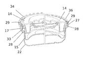
- FIG. 5 shows a vertical section through the intermediate plate and the receiving device in the open position and in the closed position of the receiving device.
- hydromounts of the type described above are prone to a high level of dynamic hardening in high-frequency ranges, which may result in adverse acoustic effects. It is further recognized according to an embodiment of the present invention that absorbers, which are fitted in the vehicle or in the mount, may serve as a remedy.
- An aspect of the invention improves, in a hydromount of the type described above, the damping properties in the high-frequency range with a simple structure and simple assembly.
- an embodiment of the invention provides, in a hydromount of the type described above, that the intermediate plate is mounted in an elastic receiving device grasping around the intermediate plate and having a pivotable supporting region.
- the intermediate plate in the fitted state, is enclosed completely at the edges by the elastic receiving device. Due to the soft mounting of the intermediate plate, the intermediate plate acts as an absorber and is capable of absorbing the arising high-frequency vibrations. Furthermore, the intermediate plate is completely decoupled from the housing, so that insulation is provided against the arising vibrations. Due to the pivotably disposed supporting region, the receiving device may have an undercut that results in a complete enclosure of the intermediate plate in the closed position of the receiving device.
- the receiving device is configured in an annular manner.
- the dimensions of the receiving device are adapted to the outer dimension of the intermediate plate.
- the receiving device may have an annular groove accommodating a radially protruding annular collar of the intermediate plate. In the closed position of the elastic receiving device, the annular collar is enclosed by the supporting regions of the receiving device.
- the receiving device has a first supporting region and a second supporting region, which are disposed so as to be pivotably movable relative to each other.
- the receiving device has projections protruding in the axial direction, which are disposed offset from each other in the circumferential direction.
- the rigidity of the elastic receiving device can be adjusted in a simple manner with the projections.
- the projections may be provided on both supporting regions.
- the receiving device is configured to be integral with the equalization membrane.
- the structure of the hydromount is thus simplified.
- the receiving device and the equalization membrane can be produced as an integral vulcanization component from an elastomeric material.
- the equalization membrane is accommodated in a cup-shaped cap having a radially stepped edge region for accommodating the receiving device.
- the frontal area of the cap is covered by a radial boss of the elastic receiving device.
- the load-bearing spring is attached by vulcanization to a supporting device having an attaching portion fixed to the cap.
- attachment can be effected, for example, by beading over the supporting portion on the cap.
- the hydromount has a housing accommodating the load-bearing spring.
- an embodiment of the invention provides a method for installing an intermediate plate in a cup-shaped cap or in a housing of a hydromount according to any one of the preceding claims.
- the method includes the following steps:
- the edge region of the intermediate plate is completely enclosed by the receiving device.
- a soft mounting of the intermediate plate is thus obtained, providing an absorber function.
- the intermediate plate is completely decoupled or insulated from a cup-shaped cap of a housing.
- FIG. 1 illustrates a hydromount 10 for mounting a motor vehicle engine on a vehicle body.
- the hydromount 10 has a load-bearing spring 11 consisting of an elastomeric material for supporting a mount core 12 vulcanized thereinto.
- the engine is attached to the mount core 12 .
- the load-bearing spring 11 delimits a working chamber 13 , which is separated from an equalization chamber 25 by means of an intermediate plate 14 .
- the equalization chamber 25 is delimited by an equalization membrane 15 , which is also referred to as a roller bellows.
- the chambers 13 and 25 are filled with a hydraulic liquid and connected to each other via a damping channel 16 incorporated into the intermediate plate 14 .
- the intermediate plate 14 has a cap part 18 and a base part 15 , into which the damping channel 16 is molded.
- the cap part 18 and the base part 19 are made from plastic.
- a decoupling chamber 21 in which a decoupling membrane 20 is accommodated, is provided in the intermediate plate 21 .
- the decoupling chamber 21 is in connection with the working chamber 13 via an opening 26 .
- the equalization membrane 15 has an receiving device 17 , which is configured to be integral with the equalization membrane 15 .
- the equalization membrane 15 is produced as an integral vulcanization component from an elastomeric material.
- An annular collar 29 which is accommodated in an annular groove 30 of the receiving device 17 , protrudes from the intermediate plate 14 .
- a detailed configuration of the receiving device 17 is described below with reference to the FIGS. 2 to 4 .
- FIGS. 2 and 4 show the receiving device 17 with the integrated equalization membrane 15 in the open position of the receiving device 17 .
- the receiving device 17 is configured in an annular manner and has projections 31 and 32 which are disposed in an offset manner in the circumferential direction and protrude in the axial direction.
- the projections 31 , 32 effect a particularly soft mounting of the intermediate plate 14 , with the rigidity being adjustable via the configuration of the projections, in particular their number.
- the equalization membrane 15 which is configured as a roller bellows, is integrally attached by vulcanization to the receiving device 17 .
- the receiving device 17 has a first supporting region 33 , which is connected to a second supporting region 34 via a connecting portion 35 .
- the projections 32 protrude from the first supporting region 33
- the projections 31 protrude from the second supporting region 34 , in each case in the axial direction.
- a radial boss 36 protrudes at the open front side.
- FIG. 3 shows the receiving device 17 in its closed position.
- the second supporting region 34 which is disposed in a pivotably movable manner, is pivoted radially inwards.
- an annular groove 30 which accommodates the annular collar 29 of the intermediate plate, is formed on the supporting device 17 .
- FIG. 5 The installation of the intermediate plate on the cup-shaped cap 22 is to be described with reference to FIG. 5 .
- the left half of FIG. 5 shows the mounting situation in the open position of the receiving device 17
- the right half of FIG. 5 shows the mounting situation of the receiving device 17 in its closed position.
- the receiving device 17 with the equalization membrane 15 attached thereto by vulcanization is placed into the cup-shaped cap 22 .
- the second supporting region 34 which is disposed in a pivotably movable manner, is folded outwards.
- the first supporting region 33 is positioned at a distance from the shoulder 28 of the cap 22 .
- FIG. 5 shows the receiving device 17 in its closed position.
- the first supporting region 33 rests on the shoulder 28 of the cap 22 .
- the edge region 27 pivots the second supporting region 34 of the receiving device 17 inwards when the intermediate plate 14 is pressed down.
- the intermediate plate 14 is thereby grasped by the supporting region 34 disposed in a pivotably movable manner.
- the edge region of the intermediate plate 14 is completely enclosed by the supporting device 17 .
- the radial boss 36 of the supporting device 17 rests on the front side of the edge region 27 .
- the receiving device 17 effects a soft mounting of the intermediate plate 14 in the hydromount 10 .
- An absorber function of the intermediate plate is thus obtained, by means of which the high-frequency vibrations can be absorbed.
- the elastic receiving device causes a complete decoupling of the intermediate plate 14 , whereby insulation can be provided against any vibrations arising.
- the receiving device 17 is produced as an integral vulcanization component with the equalization membrane 15 , the production and assembly is particularly simple. The assembly can be carried out in an automated manner.
- the recitation of “at least one of A, B and C” should be interpreted as one or more of a group of elements consisting of A, B and C, and should not be interpreted as requiring at least one of each of the listed elements A, B and C, regardless of whether A, B and C are related as categories or otherwise.
- the recitation of “A, B and/or C” or “at least one of A, B or C” should be interpreted as including any singular entity from the listed elements, e.g., A, any subset from the listed elements, e.g., A and B, or the entire list of elements A, B and C.
Landscapes
- Engineering & Computer Science (AREA)
- General Engineering & Computer Science (AREA)
- Mechanical Engineering (AREA)
- Combined Devices Of Dampers And Springs (AREA)
- Arrangement Or Mounting Of Propulsion Units For Vehicles (AREA)
Applications Claiming Priority (3)
| Application Number | Priority Date | Filing Date | Title |
|---|---|---|---|
| EP15189374.0A EP3156686B1 (de) | 2015-10-12 | 2015-10-12 | Hydrolager, insbesondere zur lagerung eines kraftfahrzeugmotors |
| EP15189374.0 | 2015-10-12 | ||
| PCT/EP2016/071524 WO2017063805A1 (de) | 2015-10-12 | 2016-09-13 | Hydrolager, insbesondere zur lagerung eines kraftfahrzeugmotors |
Publications (2)
| Publication Number | Publication Date |
|---|---|
| US20180045266A1 US20180045266A1 (en) | 2018-02-15 |
| US10316927B2 true US10316927B2 (en) | 2019-06-11 |
Family
ID=54293110
Family Applications (2)
| Application Number | Title | Priority Date | Filing Date |
|---|---|---|---|
| US15/553,584 Active US10316927B2 (en) | 2015-10-12 | 2016-09-13 | Hydromount for mounting a motor vehicle engine |
| US15/766,999 Active US10508707B2 (en) | 2015-10-12 | 2016-10-12 | Bearing system |
Family Applications After (1)
| Application Number | Title | Priority Date | Filing Date |
|---|---|---|---|
| US15/766,999 Active US10508707B2 (en) | 2015-10-12 | 2016-10-12 | Bearing system |
Country Status (7)
| Country | Link |
|---|---|
| US (2) | US10316927B2 (de) |
| EP (1) | EP3156686B1 (de) |
| JP (1) | JP6538870B2 (de) |
| KR (1) | KR102522845B1 (de) |
| CN (2) | CN107208730B (de) |
| DE (1) | DE102015015487B4 (de) |
| WO (2) | WO2017063805A1 (de) |
Cited By (2)
| Publication number | Priority date | Publication date | Assignee | Title |
|---|---|---|---|---|
| US10508707B2 (en) * | 2015-10-12 | 2019-12-17 | Audi Ag | Bearing system |
| US11268590B2 (en) * | 2017-06-01 | 2022-03-08 | Vibracoustic Se | Separation device for separating a working chamber and a compensation chamber of a hydraulically damping mount, and a hydraulically damping mount |
Families Citing this family (10)
| Publication number | Priority date | Publication date | Assignee | Title |
|---|---|---|---|---|
| DE102016112718B4 (de) * | 2016-07-12 | 2020-09-17 | Dr. Ing. H.C. F. Porsche Aktiengesellschaft | Motorlager zur Lagerung eines Antriebsaggregats eines Kraftfahrzeugs |
| US11448284B2 (en) | 2017-10-11 | 2022-09-20 | Prospira Corporation | Vibration isolation device |
| DE102018116392A1 (de) * | 2018-07-06 | 2020-01-09 | Vibracoustic Gmbh | Hydraulisch dämpfendes lager |
| DE102019114363A1 (de) * | 2019-05-28 | 2020-12-03 | Boge Elastmetall Gmbh | Hydraulisch dämpfendes Aggregatlager |
| KR102855175B1 (ko) * | 2020-03-31 | 2025-09-03 | 현대자동차주식회사 | 자동차용 엔진마운트 |
| KR102846969B1 (ko) * | 2020-04-08 | 2025-08-18 | 현대자동차주식회사 | 엔진 마운트 |
| JP7470630B2 (ja) | 2020-12-21 | 2024-04-18 | Toyo Tire株式会社 | 液封入式防振装置 |
| DE102021116125B3 (de) | 2021-06-22 | 2022-12-08 | Bayerische Motoren Werke Aktiengesellschaft | Lagerungsanordnung einer Antriebsmaschine an einem Achsträger eines Kraftfahrzeugs |
| CN113494557B (zh) * | 2021-07-27 | 2022-07-05 | 重庆长安汽车股份有限公司 | 一种解耦膜、悬置总成及车辆 |
| CN114508560B (zh) * | 2022-03-07 | 2023-03-28 | 奇瑞汽车股份有限公司 | 液压悬置结构 |
Citations (9)
| Publication number | Priority date | Publication date | Assignee | Title |
|---|---|---|---|---|
| EP0142943A2 (de) | 1983-11-23 | 1985-05-29 | General Motors Corporation | Hydro-elastomerisches Lager |
| US4588173A (en) * | 1983-11-23 | 1986-05-13 | General Motors Corporation | Hydraulic-elastomeric mount |
| US4783062A (en) * | 1987-07-01 | 1988-11-08 | General Motors Corporation | Electronic hydraulic mount-internal solenoid |
| US4783063A (en) * | 1987-01-30 | 1988-11-08 | General Motors Corporation | Hydraulic-elastomeric mount displacement decoupler |
| US4901986A (en) * | 1988-03-07 | 1990-02-20 | General Motors Corporation | Air bladder controlled hydraulic engine mount |
| FR2708695A1 (fr) * | 1993-08-06 | 1995-02-10 | Continental Ag | Support de Moteur. |
| EP0737825A1 (de) | 1995-04-14 | 1996-10-16 | General Motors Corporation | Hydraulische Motorstütze |
| US8894051B2 (en) * | 2010-01-21 | 2014-11-25 | Toyo Tire & Rubber Co., Ltd. | Liquid-sealed vibration isolator |
| US20180291978A1 (en) * | 2015-10-12 | 2018-10-11 | Audi Ag | Bearing system |
Family Cites Families (28)
| Publication number | Priority date | Publication date | Assignee | Title |
|---|---|---|---|---|
| JPH06100243B2 (ja) | 1987-08-21 | 1994-12-12 | 東海ゴム工業株式会社 | 流体封入式マウント装置 |
| US4915365A (en) * | 1987-09-04 | 1990-04-10 | The Standard Products Company | Elastomeric engine mount with hydraulic damping |
| DE3801108A1 (de) * | 1988-01-16 | 1989-07-27 | Audi Ag | Hydraulisches motorlager |
| US4840358A (en) * | 1988-03-28 | 1989-06-20 | General Motors Corporation | Hydraulic engine mount with air bladder tuning |
| DE4100370C1 (en) | 1991-01-09 | 1992-06-17 | Boge Ag, 5208 Eitorf, De | Car engine hydraulically damping rubber mounting - has partition, whose second half limits two chambers by its axial front sides |
| US5516084A (en) | 1995-04-14 | 1996-05-14 | General Motors Corporation | Hydraulic engine mount with diaphragm decoupler |
| JP3458322B2 (ja) * | 1997-03-28 | 2003-10-20 | 東洋ゴム工業株式会社 | 液封入防振装置 |
| US6412760B2 (en) | 1999-12-27 | 2002-07-02 | Toyoda Gosei Co., Ltd. | Liquid-filled type vibration isolator |
| ES2271257T3 (es) | 2001-06-22 | 2007-04-16 | Yamashita Rubber Kabushiki Kaisha | Dispositivo para el control de vibraciones de anillo liquido. |
| JP3757829B2 (ja) | 2001-07-16 | 2006-03-22 | 東海ゴム工業株式会社 | 流体封入式防振装置 |
| DE10307680A1 (de) * | 2003-02-21 | 2004-09-30 | Carl Freudenberg Kg | Hydrolager |
| US20040188901A1 (en) * | 2003-03-31 | 2004-09-30 | Cooper Technology Service, Llc | Engine mount |
| JP4228219B2 (ja) | 2004-03-22 | 2009-02-25 | 東海ゴム工業株式会社 | 流体封入式防振装置 |
| DE102005004928B4 (de) | 2005-02-02 | 2006-10-12 | Carl Freudenberg Kg | Hydrolager |
| JP4411659B2 (ja) | 2005-03-14 | 2010-02-10 | 東海ゴム工業株式会社 | 流体封入式防振装置 |
| DE102005059026A1 (de) * | 2005-12-10 | 2007-06-14 | Contitech Vibration Control Gmbh | Bypass-schaltbares Hydrolager mit Entkopplungsmembran |
| JP4842086B2 (ja) | 2006-10-20 | 2011-12-21 | 東海ゴム工業株式会社 | 流体封入式防振装置 |
| DE102007058191B4 (de) | 2006-12-05 | 2016-04-07 | Honda Motor Co., Ltd. | Flüssigkeitseinschließende Schwingungs-Isoliervorrichtung |
| JP5210558B2 (ja) * | 2007-07-12 | 2013-06-12 | 株式会社ブリヂストン | 防振装置 |
| DE102008037471A1 (de) * | 2008-10-20 | 2010-04-29 | Contitech Vibration Control Gmbh | Hydrolager |
| JP2010223406A (ja) * | 2009-03-25 | 2010-10-07 | Bridgestone Corp | 防振装置 |
| JP5883312B2 (ja) * | 2011-03-25 | 2016-03-15 | 住友理工株式会社 | 流体封入式防振装置とその製造方法 |
| JP6189674B2 (ja) * | 2013-08-14 | 2017-08-30 | 山下ゴム株式会社 | 液封マウント |
| CN104100673B (zh) | 2014-07-22 | 2016-03-02 | 建新赵氏集团有限公司 | 汽车动力总成半主动控制液压悬置 |
| DE102014118502B4 (de) | 2014-12-12 | 2018-09-06 | Vibracoustic Gmbh | Lageranordnung zum Lagern eines Motors |
| JP6460781B2 (ja) * | 2014-12-25 | 2019-01-30 | Toyo Tire株式会社 | 液体封入式防振装置 |
| DE102015215563B4 (de) | 2015-08-14 | 2020-02-27 | Audi Ag | Lagerungseinrichtung |
| US9895965B2 (en) | 2015-10-27 | 2018-02-20 | Ford Global Technologies, Llc | Passively controlled dual-state vacuum switchable mount |
-
2015
- 2015-10-12 EP EP15189374.0A patent/EP3156686B1/de active Active
- 2015-11-28 DE DE102015015487.7A patent/DE102015015487B4/de active Active
-
2016
- 2016-09-13 WO PCT/EP2016/071524 patent/WO2017063805A1/de not_active Ceased
- 2016-09-13 JP JP2017549495A patent/JP6538870B2/ja active Active
- 2016-09-13 CN CN201680007518.5A patent/CN107208730B/zh active Active
- 2016-09-13 KR KR1020177022941A patent/KR102522845B1/ko active Active
- 2016-09-13 US US15/553,584 patent/US10316927B2/en active Active
- 2016-10-12 US US15/766,999 patent/US10508707B2/en active Active
- 2016-10-12 WO PCT/EP2016/001689 patent/WO2017063736A1/de not_active Ceased
- 2016-10-12 CN CN201680059431.2A patent/CN108138892B/zh active Active
Patent Citations (9)
| Publication number | Priority date | Publication date | Assignee | Title |
|---|---|---|---|---|
| EP0142943A2 (de) | 1983-11-23 | 1985-05-29 | General Motors Corporation | Hydro-elastomerisches Lager |
| US4588173A (en) * | 1983-11-23 | 1986-05-13 | General Motors Corporation | Hydraulic-elastomeric mount |
| US4783063A (en) * | 1987-01-30 | 1988-11-08 | General Motors Corporation | Hydraulic-elastomeric mount displacement decoupler |
| US4783062A (en) * | 1987-07-01 | 1988-11-08 | General Motors Corporation | Electronic hydraulic mount-internal solenoid |
| US4901986A (en) * | 1988-03-07 | 1990-02-20 | General Motors Corporation | Air bladder controlled hydraulic engine mount |
| FR2708695A1 (fr) * | 1993-08-06 | 1995-02-10 | Continental Ag | Support de Moteur. |
| EP0737825A1 (de) | 1995-04-14 | 1996-10-16 | General Motors Corporation | Hydraulische Motorstütze |
| US8894051B2 (en) * | 2010-01-21 | 2014-11-25 | Toyo Tire & Rubber Co., Ltd. | Liquid-sealed vibration isolator |
| US20180291978A1 (en) * | 2015-10-12 | 2018-10-11 | Audi Ag | Bearing system |
Cited By (2)
| Publication number | Priority date | Publication date | Assignee | Title |
|---|---|---|---|---|
| US10508707B2 (en) * | 2015-10-12 | 2019-12-17 | Audi Ag | Bearing system |
| US11268590B2 (en) * | 2017-06-01 | 2022-03-08 | Vibracoustic Se | Separation device for separating a working chamber and a compensation chamber of a hydraulically damping mount, and a hydraulically damping mount |
Also Published As
| Publication number | Publication date |
|---|---|
| DE102015015487A1 (de) | 2017-04-13 |
| JP2018515722A (ja) | 2018-06-14 |
| US20180045266A1 (en) | 2018-02-15 |
| EP3156686A1 (de) | 2017-04-19 |
| CN108138892B (zh) | 2020-08-25 |
| US10508707B2 (en) | 2019-12-17 |
| KR102522845B1 (ko) | 2023-04-18 |
| WO2017063736A1 (de) | 2017-04-20 |
| JP6538870B2 (ja) | 2019-07-03 |
| WO2017063805A1 (de) | 2017-04-20 |
| EP3156686B1 (de) | 2020-04-15 |
| CN107208730B (zh) | 2020-05-29 |
| US20180291978A1 (en) | 2018-10-11 |
| KR20180067460A (ko) | 2018-06-20 |
| CN108138892A (zh) | 2018-06-08 |
| DE102015015487B4 (de) | 2025-03-20 |
| CN107208730A (zh) | 2017-09-26 |
Similar Documents
| Publication | Publication Date | Title |
|---|---|---|
| US20180045266A1 (en) | Hydromount for mounting a motor vehicle engine | |
| CN108223676B (zh) | 发动机悬置及其制造方法 | |
| JP3629485B2 (ja) | 液封入式防振装置 | |
| JP5331329B2 (ja) | 液入り防振装置 | |
| US11143259B2 (en) | Vibration absorber | |
| US20050098374A1 (en) | Mount assembly for automotive power plant | |
| US20080029942A1 (en) | Vehicle mount and method | |
| US10941832B2 (en) | Hydromount | |
| JP5221442B2 (ja) | 防振装置 | |
| JP2009243503A (ja) | ストラットマウント | |
| JPWO2010126059A1 (ja) | 防振装置 | |
| JP4718137B2 (ja) | 防振装置 | |
| CA2464028A1 (en) | Tuned vibration absorber | |
| KR101585432B1 (ko) | 차량용 엔진마운트 | |
| KR20160013609A (ko) | 차량용 세미 액티브 엔진 마운트 | |
| KR20170029677A (ko) | 엔진마운트 | |
| JP2012207708A (ja) | 防振装置の製造方法及び防振装置 | |
| JP6297906B2 (ja) | 液封入式防振装置 | |
| EP3717776B1 (de) | Vakuumpumpe zur befestigung an einem rahmen eines fahrzeugs | |
| JP2022147770A (ja) | 防振装置 | |
| KR101845455B1 (ko) | 차량용 하이드로 마운트 멤브레인 노이즈 저감구조 | |
| KR101551952B1 (ko) | 공압식 엔진마운트 | |
| JP5893482B2 (ja) | 液封入式防振装置 | |
| KR101857032B1 (ko) | 차량용 하이드로마운트 | |
| JP4286200B2 (ja) | 液体封入式防振マウント装置 |
Legal Events
| Date | Code | Title | Description |
|---|---|---|---|
| AS | Assignment |
Owner name: VIBRACOUSTIC GMBH, GERMANY Free format text: ASSIGNMENT OF ASSIGNORS INTEREST;ASSIGNORS:SCHEMER, THOMAS;STOECKER, TIMO;REEL/FRAME:043414/0819 Effective date: 20170622 |
|
| STPP | Information on status: patent application and granting procedure in general |
Free format text: NOTICE OF ALLOWANCE MAILED -- APPLICATION RECEIVED IN OFFICE OF PUBLICATIONS |
|
| STPP | Information on status: patent application and granting procedure in general |
Free format text: PUBLICATIONS -- ISSUE FEE PAYMENT RECEIVED |
|
| STPP | Information on status: patent application and granting procedure in general |
Free format text: PUBLICATIONS -- ISSUE FEE PAYMENT VERIFIED |
|
| STCF | Information on status: patent grant |
Free format text: PATENTED CASE |
|
| AS | Assignment |
Owner name: VIBRACOUSTIC AG, GERMANY Free format text: ASSIGNMENT OF ASSIGNORS INTEREST;ASSIGNOR:VIBRACOUSTIC GMBH;REEL/FRAME:057687/0381 Effective date: 20190116 |
|
| AS | Assignment |
Owner name: VIBRACOUSTIC SE, GERMANY Free format text: CHANGE OF NAME;ASSIGNOR:VIBRACOUSTIC AG;REEL/FRAME:058357/0478 Effective date: 20201207 |
|
| MAFP | Maintenance fee payment |
Free format text: PAYMENT OF MAINTENANCE FEE, 4TH YEAR, LARGE ENTITY (ORIGINAL EVENT CODE: M1551); ENTITY STATUS OF PATENT OWNER: LARGE ENTITY Year of fee payment: 4 |