US10309472B2 - Disk brake and drive element of and adjusting device of a disk brake - Google Patents
Disk brake and drive element of and adjusting device of a disk brake Download PDFInfo
- Publication number
- US10309472B2 US10309472B2 US15/543,056 US201615543056A US10309472B2 US 10309472 B2 US10309472 B2 US 10309472B2 US 201615543056 A US201615543056 A US 201615543056A US 10309472 B2 US10309472 B2 US 10309472B2
- Authority
- US
- United States
- Prior art keywords
- brake
- slotted guide
- disk
- lever
- drive element
- Prior art date
- Legal status (The legal status is an assumption and is not a legal conclusion. Google has not performed a legal analysis and makes no representation as to the accuracy of the status listed.)
- Active
Links
Images


Classifications
-
- F—MECHANICAL ENGINEERING; LIGHTING; HEATING; WEAPONS; BLASTING
- F16—ENGINEERING ELEMENTS AND UNITS; GENERAL MEASURES FOR PRODUCING AND MAINTAINING EFFECTIVE FUNCTIONING OF MACHINES OR INSTALLATIONS; THERMAL INSULATION IN GENERAL
- F16D—COUPLINGS FOR TRANSMITTING ROTATION; CLUTCHES; BRAKES
- F16D55/00—Brakes with substantially-radial braking surfaces pressed together in axial direction, e.g. disc brakes
- F16D55/02—Brakes with substantially-radial braking surfaces pressed together in axial direction, e.g. disc brakes with axially-movable discs or pads pressed against axially-located rotating members
- F16D55/22—Brakes with substantially-radial braking surfaces pressed together in axial direction, e.g. disc brakes with axially-movable discs or pads pressed against axially-located rotating members by clamping an axially-located rotating disc between movable braking members, e.g. movable brake discs or brake pads
- F16D55/224—Brakes with substantially-radial braking surfaces pressed together in axial direction, e.g. disc brakes with axially-movable discs or pads pressed against axially-located rotating members by clamping an axially-located rotating disc between movable braking members, e.g. movable brake discs or brake pads with a common actuating member for the braking members
- F16D55/225—Brakes with substantially-radial braking surfaces pressed together in axial direction, e.g. disc brakes with axially-movable discs or pads pressed against axially-located rotating members by clamping an axially-located rotating disc between movable braking members, e.g. movable brake discs or brake pads with a common actuating member for the braking members the braking members being brake pads
- F16D55/2255—Brakes with substantially-radial braking surfaces pressed together in axial direction, e.g. disc brakes with axially-movable discs or pads pressed against axially-located rotating members by clamping an axially-located rotating disc between movable braking members, e.g. movable brake discs or brake pads with a common actuating member for the braking members the braking members being brake pads in which the common actuating member is pivoted
-
- F—MECHANICAL ENGINEERING; LIGHTING; HEATING; WEAPONS; BLASTING
- F16—ENGINEERING ELEMENTS AND UNITS; GENERAL MEASURES FOR PRODUCING AND MAINTAINING EFFECTIVE FUNCTIONING OF MACHINES OR INSTALLATIONS; THERMAL INSULATION IN GENERAL
- F16D—COUPLINGS FOR TRANSMITTING ROTATION; CLUTCHES; BRAKES
- F16D55/00—Brakes with substantially-radial braking surfaces pressed together in axial direction, e.g. disc brakes
- F16D55/02—Brakes with substantially-radial braking surfaces pressed together in axial direction, e.g. disc brakes with axially-movable discs or pads pressed against axially-located rotating members
- F16D55/22—Brakes with substantially-radial braking surfaces pressed together in axial direction, e.g. disc brakes with axially-movable discs or pads pressed against axially-located rotating members by clamping an axially-located rotating disc between movable braking members, e.g. movable brake discs or brake pads
- F16D55/224—Brakes with substantially-radial braking surfaces pressed together in axial direction, e.g. disc brakes with axially-movable discs or pads pressed against axially-located rotating members by clamping an axially-located rotating disc between movable braking members, e.g. movable brake discs or brake pads with a common actuating member for the braking members
- F16D55/225—Brakes with substantially-radial braking surfaces pressed together in axial direction, e.g. disc brakes with axially-movable discs or pads pressed against axially-located rotating members by clamping an axially-located rotating disc between movable braking members, e.g. movable brake discs or brake pads with a common actuating member for the braking members the braking members being brake pads
- F16D55/226—Brakes with substantially-radial braking surfaces pressed together in axial direction, e.g. disc brakes with axially-movable discs or pads pressed against axially-located rotating members by clamping an axially-located rotating disc between movable braking members, e.g. movable brake discs or brake pads with a common actuating member for the braking members the braking members being brake pads in which the common actuating member is moved axially, e.g. floating caliper disc brakes
- F16D55/2265—Brakes with substantially-radial braking surfaces pressed together in axial direction, e.g. disc brakes with axially-movable discs or pads pressed against axially-located rotating members by clamping an axially-located rotating disc between movable braking members, e.g. movable brake discs or brake pads with a common actuating member for the braking members the braking members being brake pads in which the common actuating member is moved axially, e.g. floating caliper disc brakes the axial movement being guided by one or more pins engaging bores in the brake support or the brake housing
-
- F—MECHANICAL ENGINEERING; LIGHTING; HEATING; WEAPONS; BLASTING
- F16—ENGINEERING ELEMENTS AND UNITS; GENERAL MEASURES FOR PRODUCING AND MAINTAINING EFFECTIVE FUNCTIONING OF MACHINES OR INSTALLATIONS; THERMAL INSULATION IN GENERAL
- F16D—COUPLINGS FOR TRANSMITTING ROTATION; CLUTCHES; BRAKES
- F16D65/00—Parts or details
- F16D65/14—Actuating mechanisms for brakes; Means for initiating operation at a predetermined position
- F16D65/16—Actuating mechanisms for brakes; Means for initiating operation at a predetermined position arranged in or on the brake
- F16D65/18—Actuating mechanisms for brakes; Means for initiating operation at a predetermined position arranged in or on the brake adapted for drawing members together, e.g. for disc brakes
-
- F—MECHANICAL ENGINEERING; LIGHTING; HEATING; WEAPONS; BLASTING
- F16—ENGINEERING ELEMENTS AND UNITS; GENERAL MEASURES FOR PRODUCING AND MAINTAINING EFFECTIVE FUNCTIONING OF MACHINES OR INSTALLATIONS; THERMAL INSULATION IN GENERAL
- F16D—COUPLINGS FOR TRANSMITTING ROTATION; CLUTCHES; BRAKES
- F16D65/00—Parts or details
- F16D65/38—Slack adjusters
- F16D65/40—Slack adjusters mechanical
- F16D65/52—Slack adjusters mechanical self-acting in one direction for adjusting excessive play
- F16D65/56—Slack adjusters mechanical self-acting in one direction for adjusting excessive play with screw-thread and nut
- F16D65/567—Slack adjusters mechanical self-acting in one direction for adjusting excessive play with screw-thread and nut for mounting on a disc brake
-
- F—MECHANICAL ENGINEERING; LIGHTING; HEATING; WEAPONS; BLASTING
- F16—ENGINEERING ELEMENTS AND UNITS; GENERAL MEASURES FOR PRODUCING AND MAINTAINING EFFECTIVE FUNCTIONING OF MACHINES OR INSTALLATIONS; THERMAL INSULATION IN GENERAL
- F16D—COUPLINGS FOR TRANSMITTING ROTATION; CLUTCHES; BRAKES
- F16D2121/00—Type of actuator operation force
- F16D2121/14—Mechanical
-
- F—MECHANICAL ENGINEERING; LIGHTING; HEATING; WEAPONS; BLASTING
- F16—ENGINEERING ELEMENTS AND UNITS; GENERAL MEASURES FOR PRODUCING AND MAINTAINING EFFECTIVE FUNCTIONING OF MACHINES OR INSTALLATIONS; THERMAL INSULATION IN GENERAL
- F16D—COUPLINGS FOR TRANSMITTING ROTATION; CLUTCHES; BRAKES
- F16D2125/00—Components of actuators
- F16D2125/18—Mechanical mechanisms
- F16D2125/20—Mechanical mechanisms converting rotation to linear movement or vice versa
- F16D2125/22—Mechanical mechanisms converting rotation to linear movement or vice versa acting transversely to the axis of rotation
- F16D2125/26—Cranks
-
- F—MECHANICAL ENGINEERING; LIGHTING; HEATING; WEAPONS; BLASTING
- F16—ENGINEERING ELEMENTS AND UNITS; GENERAL MEASURES FOR PRODUCING AND MAINTAINING EFFECTIVE FUNCTIONING OF MACHINES OR INSTALLATIONS; THERMAL INSULATION IN GENERAL
- F16D—COUPLINGS FOR TRANSMITTING ROTATION; CLUTCHES; BRAKES
- F16D2125/00—Components of actuators
- F16D2125/18—Mechanical mechanisms
- F16D2125/20—Mechanical mechanisms converting rotation to linear movement or vice versa
- F16D2125/22—Mechanical mechanisms converting rotation to linear movement or vice versa acting transversely to the axis of rotation
- F16D2125/28—Cams; Levers with cams
- F16D2125/32—Cams; Levers with cams acting on one cam follower
-
- F—MECHANICAL ENGINEERING; LIGHTING; HEATING; WEAPONS; BLASTING
- F16—ENGINEERING ELEMENTS AND UNITS; GENERAL MEASURES FOR PRODUCING AND MAINTAINING EFFECTIVE FUNCTIONING OF MACHINES OR INSTALLATIONS; THERMAL INSULATION IN GENERAL
- F16D—COUPLINGS FOR TRANSMITTING ROTATION; CLUTCHES; BRAKES
- F16D2125/00—Components of actuators
- F16D2125/18—Mechanical mechanisms
- F16D2125/20—Mechanical mechanisms converting rotation to linear movement or vice versa
- F16D2125/34—Mechanical mechanisms converting rotation to linear movement or vice versa acting in the direction of the axis of rotation
- F16D2125/40—Screw-and-nut
-
- F—MECHANICAL ENGINEERING; LIGHTING; HEATING; WEAPONS; BLASTING
- F16—ENGINEERING ELEMENTS AND UNITS; GENERAL MEASURES FOR PRODUCING AND MAINTAINING EFFECTIVE FUNCTIONING OF MACHINES OR INSTALLATIONS; THERMAL INSULATION IN GENERAL
- F16D—COUPLINGS FOR TRANSMITTING ROTATION; CLUTCHES; BRAKES
- F16D2125/00—Components of actuators
- F16D2125/18—Mechanical mechanisms
- F16D2125/58—Mechanical mechanisms transmitting linear movement
- F16D2125/64—Levers
Definitions
- the invention relates to a disk brake for a vehicle and preferably for a commercial vehicle in accordance with the preamble of patent claim 1 .
- the invention relates to a drive element of an adjusting device for compensating for the brake lining and brake disk wear of a disk brake as claimed in patent claim 13 .
- EP 0 739 459 B1 has disclosed a disk brake which is suitable for use in commercial vehicle brakes and is provided with a brake lever which is arranged pivotably within a brake caliper.
- a mechanical adjusting device likewise within the brake caliper, for compensating for the brake lining and brake disk wear which occurs during braking operation.
- a mechanism furthermore, which couples the brake lever to a drive element of the adjusting device.
- a pin which is fastened in the end face of the brake application shaft of the brake lever and extends from there to the outside serves as a lever-side mechanism element.
- a sliding block, into which the free end of the pin engages, serves, inter alia, as an adjustment-side mechanism element. The sliding block is guided longitudinally in a cutout on the outside of the adjusting device. The cutout extends in the longitudinal direction of the adjusting axis of the adjusting device.
- a disk brake of the generic type is known from DE 10 2008 037 774 B3.
- Said disk brake is also provided with an integrated adjusting device for compensating for the brake lining and brake disk wear which occurs during braking operation, the adjustment being derived from the pivoting movement of the brake lever by means of a mechanism.
- the brake lever is of fork-shaped design and in this way has a clearance which affords space for the adjusting device.
- the brake application shaft is divided into two spatially separated sections.
- the lever-side mechanism element of the mechanism is a pin which is fastened in an oblique arrangement in the end face of the one section of the brake application shaft.
- the invention is based on the object of providing as much installation space as possible for the bearings which are arranged on the brake application shaft and transmit the braking forces.
- a disk brake for a vehicle having the features of patent claim 1 is proposed for achieving said object.
- the first mechanism element of the mechanism which couples the brake lever to the drive element of the adjusting device is arranged at the inner end of the lever arm in the plane which is defined by the pivoting movement of the lever arm. In this way, the mechanism is situated in a region of the brake application device where no transmission of brake application forces takes place and where transmission of this type would also not be appropriate.
- the lever-side mechanism element is situated at the inner end of the lever arm where the brake lever splits in a fork-shaped manner into a first limb which leads to a first section and a second limb which leads to a second section of the brake application shaft. Therefore, the lever-side mechanism element is situated at the same time at a location which is situated between the adjusting axis and that support for the force element which is arranged at the free end of the lever arm.
- a carrier on which a fastening region is configured for mounting the drive element on the adjusting device fixedly so as to rotate with it
- a slotted guide which is arranged on the carrier in the form of a simple or double arm and describes an arc which is curved to the outside in relation to the fastening region of the carrier.
- one of the two mechanism elements is a slotted guide which is designed as a single or double arm, which can also be a refinement of the disk brake according to the invention, whereas the other mechanism element is the element which is guided along said slotted guide.
- the slotted guide preferably extends at least over part of its overall length obliquely with respect to the adjusting axis of the adjusting device.
- the brake adjustment manages largely without play between adjacent faces or edges, the risk is considerably reduced of the adjustment being irritated or influenced negatively in another way, for example, by way of shocks or vibrations of the brake.
- the slotted guide extends over its entire length obliquely with respect to the plane which is defined by the pivoting movement of the lever arm.
- the angle, at which the slotted guide extends obliquely with respect to the plane which is defined by the pivoting movement of the lever arm can vary over the length of the slotted guide. In particular, said angle can become smaller during the brake application, that is to say with increasing pivoting of the lever.
- the slotted guide describes an arc which is curved to the outside in relation to the adjusting axis and the curved course of which corresponds at least over a part length to the path which is taken by the inner end of the lever arm during its pivoting movement.
- the drive element is composed of the slotted guide, which is designed as a single or double arm, and a carrier, to which the slotted guide is fastened, a fastening region for mounting the drive element on the adjusting device fixedly so as to rotate with it being configured on the carrier.
- the slotted guide and the carrier consist of the same material in one piece, preferably of plastic.
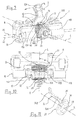
- FIG. 1 shows a perspective illustration of a first embodiment of a brake application device which is a constituent part of a vehicle disk brake
- FIG. 2 shows the objects according to FIG. 1 , the lever being illustrated in a changed position during a progressing brake application
- FIG. 3 shows a perspective illustration only of a drive element of an adjusting device for compensating for the brake lining and brake disk wear of the disk brake
- FIG. 4 shows an outline illustration in respect of the mechanism which is used in the brake application device
- FIG. 5 shows the mechanism according to FIG. 4 in another position
- FIG. 6 shows a modified outline illustration in respect of the mechanism which is used in the brake application device
- FIG. 7 shows a plan view of a second embodiment of a brake application device which is a constituent part of a vehicle disk brake
- FIG. 8 shows the brake application apparatus according to FIG. 7 in one view
- FIG. 9 shows a perspective illustration of a third embodiment of a brake application device which is a constituent part of a vehicle disk brake
- FIG. 10 shows a plan view of the brake application device according to FIG. 9 .
- FIG. 11 shows a perspective illustration only of the drive element of the adjusting device
- FIG. 12 shows a perspective illustration of a fourth embodiment of a brake application device which is a constituent part of a vehicle disk brake
- FIG. 13 shows the objects according to FIG. 12 , the lever being illustrated in a changed position during a progressing brake application
- FIG. 14 shows a perspective illustration only of the drive element of the adjusting device
- FIG. 15 shows the drive element according to FIG. 14 in a plan view
- FIG. 16 shows a perspective illustration of an embodiment of the drive element which is varied in comparison with FIG. 14 .
- FIG. 17 shows the drive element according to FIG. 16 in a plan view.
- the drawings do not illustrate an entire disk brake, as installed, in particular, as a commercial vehicle brake which is actuated by compressed air, but rather only the brake application device 5 of the disk brake.
- the disk brake including its brake caliper, the brake disk, the brake linings on both sides of the brake disk, reference is made, insofar as the customary design of a disk brake of this type is proposed, to disk brakes as described, for example, in DE 10 2008 037 774 B3 and in DE 43 07 018 A1.
- the main constituent parts of the brake application device 5 are a brake lever 10 which is mounted pivotably in a brake caliper of the disk brake, and a pressure piece 8 which operates against at least one of the brake linings of the disk brake, here in the shape of a crossmember which extends over the entire width of the brake lever 10 .
- the brake lever 10 is composed of a brake application shaft 11 which is divided into two sections, and a lever arm 12 .
- the brake application shaft 11 is supported on its rear side from the inside against the brake caliper of the disk brake. Said support takes place via a pivot bearing, to which end two split bearings are arranged between the brake application shaft 11 and a corresponding face in the brake caliper.
- the brake application shaft 11 is supported pivotably via two further split bearings 17 against the pressure piece 8 which is of recess-shaped design in this region.
- the brake application shaft 11 is configured as an eccentric. This is because the rear-side split bearings which are supported against the brake caliper have a rotational axis A 2 which is arranged offset vertically in comparison with the rotational axis A 1 of the split bearings 17 which are supported against the pressure piece 8 . During a rotation of the brake application shaft 11 about the rotational axis A 2 which defines the rotational movement with respect to the brake caliper, a forward movement of the pressure piece 8 therefore occurs in the direction of the brake disk of the disk brake, with the result that the brake is applied.
- the lever arm 12 serves to rotate the brake application shaft 11 by means of a boosting lever action.
- the center line of said lever arm 12 extends at a right angle with respect to the brake application shaft 11 .
- the lever arm 12 is provided with a support 16 .
- the latter is preferably of spherical-like design and defines a supporting point, against which the force element of the disk brake operates. In the case of disk brakes which are actuated by compressed air, said force element is the tappet of a pneumatic brake cylinder.
- the brake lever 10 is fork-shaped overall and branches, starting from the lever arm 12 which is arranged on the pivoting center line, into two limbs 13 A, 13 B, of which the one limb 13 A is connected to the first section 11 A of the brake application shaft 11 , and the second limb 13 B is connected to the second section 11 B of the brake application shaft 11 .
- the brake lever 10 has a clearance 40 to the inside in an extension of the lever arm 12 .
- Said clearance 40 is delimited, inter alia, by way of the end faces which face one another of the sections 11 A, 11 B of the brake application shaft 11 , and, toward the lever arm 12 , by way of the inner end 12 B of the lever arm 12 .
- the inner end 12 B of the lever arm 12 is that location on the lever arm 12 , at which the limbs 13 A, 13 B branch. Said location is situated between the rotational axis A 2 , about which the brake lever 10 pivots relative to the brake caliper, and the support 16 . Said location is preferably situated at approximately one third of the distance between the rotational axis A 2 , about which the brake lever 10 pivots relative to the brake caliper, and the support 16 .
- Constituent parts of the adjusting device 20 are, inter alia, a drive element 10 , an output element which reduces the air play of the brake, and, in the movement path between the drive element and the output element, a one-way clutch and an overload element.
- the adjusting axis L extends in the brake application direction and therefore perpendicularly with respect to the plane of the brake disk.
- the adjusting axis L extends through the clearance 40 of the brake lever 10 . It is preferably arranged in such a way that it intersects one of the rotational or pivoting axes A 1 , A 2 of the brake lever 10 .
- the adjusting mechanism is composed of a first mechanism element 31 which is situated on the brake lever 10 and a second mechanism element 32 which interacts therewith and is situated on the adjusting device 20 .
- the two elements 31 , 32 preferably engage into one another virtually without play, in order thus to prevent irritations of the brake adjustment as a result of shocks or vibrations of the disk brake.
- the first (that is to say, the lever-side) mechanism element 31 is arranged in the clearance 40 at the inner end 12 B of the lever arm 12 and therefore where the two limbs 13 A, 13 B branch.
- the first mechanism element 31 is situated at a location in that plane E, within which the lever arm 12 carries out its pivoting movement S during the brake application of the brake.
- the adjusting axis L also lies in said plane E.
- the first mechanism element 31 is situated at a location between the adjusting axis L and the support 16 for the force element, which support 16 is arranged at the other end 12 A of the lever arm 12 .
- the first element 31 of the adjusting mechanism is a pin or bolt which is fastened in the brake lever 10 on the pivoting center line of the lever arm 12 and extends with its free end toward the adjusting axis L.
- the second (that is to say, the adjustment-side) element 32 of the adjusting mechanism is a slotted guide comprising two arms which run equidistantly and a slot 33 which is arranged in between.
- the pin 31 is capable of moving along the slotted guide 32 , said pin 31 driving the drive element 27 and setting it in rotation about the adjusting axis L.
- the slotted guide 32 runs on a slotted guide section 32 B and therefore at least over a part of the entire length of the slotted guide obliquely with respect to the adjusting axis L.
- the slotted guide 32 describes an arc which is curved to the outside in relation to the adjusting axis L.
- the curvature of said arc follows the likewise curved movement of the pin 31 which is arranged at the inner end 12 B of the lever arm 12 during the pivoting of the brake lever 10 .
- said curvature can be in relation to one of the rotational axes A 1 , A 2 of the brake lever 10 as a curvature center axis.
- the drive element 27 (illustrated in FIG. 3 ) of the adjusting device 20 preferably consists of plastic. It is composed in one piece of the slotted guide 32 , which is designed as a double arm with a slot guide, and a carrier 35 , on which the double arm is integrally formed.
- the carrier 35 has a fastening region 36 for mounting the drive element 27 on a drive shaft of the adjusting device 20 fixedly so as to rotate with it.
- Said fastening region 36 is designed here as a ring.
- Its inner edge 39 is designed as a polygon which is seated without play in the circumferential direction on a corresponding polygon of the drive shaft of the adjusting device.
- the angle, at which the slotted guide 32 which is configured as a groove 33 here runs with respect to the adjusting axis L, can vary over the length of the slotted guide 32 .
- the slotted guide section 32 A which is then in play-free engagement with the pin 31 can run parallel to the adjusting axis L, with the result that the drive element 27 does not yet experience a rotation.
- a clear rotation of the drive element 27 about the adjusting axis L takes place only in the further course of the movement of the brake lever, on account of the oblique arrangement of the adjoining slotted guide section 32 B.
- the drive element 27 can also be configured integrally with the first adjusting element of the brake.
- a desired adjusting characteristic can be fixed by way of a correspondingly oblique course of the slotted guide section 32 B. This provides the option to give the brake a defined adjusting characteristic by way of the selection of a defined drive element 27 or, for example, to provide different brake types with a drive element 27 which is adapted in terms of its slotted guide course, in the case of an identical adjusting device and an identical brake lever 10 .
- the difference from the known drive systems in which a rotary drive movement of the brake lever 10 is converted into a rotary output movement of the adjusting device 20 with rotational axes which are assigned at an angle, consists in the utilization of an axial longitudinal movement which is converted into a rotary output movement.
- lever-side first mechanism element 31 experiences a pivoting movement about the rotational axis A 1 or A 2 which extends transversely with respect to the axis L, said rotation does not produce a drive movement on the second mechanism element 32 . Only the axial relative movement parallel to the axis L of the first mechanism element 31 brings about the rotary drive of the drive element 27 .
- the first mechanism element 31 comes into contact in the one pivoting direction of the brake lever 10 with the slotted guide face which is ramp-like with respect to the axis L, and always pressing said slotted guide face away laterally.
- the first mechanism element 31 comes into contact with the slotted guide face which is ramp-like with respect to the axis L, and always presses said slotted guide face away laterally.
- the slotted guide faces are spaced apart in an unvarying manner over their length, and said spacing is dimensioned in such a way that the pin 31 lies virtually without play between the slotted guide faces or encloses them from the outside.
- This play-free insertion makes it possible to keep the mechanism elements 31 and 32 permanently in lateral engagement without appreciable hysteresis and at the same time to fixedly stipulate the idle stroke (without a transmission of movement) and the drive stroke (with a transmission of movement) via different curvature angles of the one mechanism element.
- the permanent lateral contact of the mechanism elements 31 , 32 with respect to one another rules out an undesired influence of the adjustment by way of, for example, vibrations, since the mechanism elements 31 and 32 do not perform any uncontrolled lateral movements with respect to one another, for instance lateral to and fro knocking.
- FIGS. 4 to 6 outline the indicated principle and show the pure axial drive which is converted into a rotational movement.
- the pin 31 is at a right angle on the axis L.
- the advancing of the pin parallel to the axis L brings about a rotational movement in the rotational body or mechanism element 32 counter to the clockwise direction via the one slotted guide face.
- Pushing back on the same straight line brings about a rotational movement in the opposite direction via the opposite slotted guide face.
- FIG. 5 shows how the pivoting movement of the brake lever 10 has an effect on the axis A 1 or A 2 at a right angle with respect to the axis L in the mechanism.
- the slotted guide is adapted to the pivoting course of the one mechanism element merely by the other mechanism element being of arcuate configuration with respect to the axis L, parallel to the pivoting course.
- the pure rotational component of the pivoting movement does not have an influence on the rotary drive, however.
- the axial component of the pivoting movement brings about the sliding of the mechanism elements 31 , 32 on one another, and therefore the rotary drive.
- the utilization of the axial relative movement for a sufficient rotary drive is possible.
- the adjusting mechanism operates in an optimum manner in an angular range between 80° and 100°.
- FIGS. 7 and 8 show a second embodiment.
- the first mechanism element 32 which is arranged on the brake lever 10 is a slotted guide in the configuration of a groove, into which a pin which forms the second mechanism element 32 engages with its pin end.
- the pin forms the drive element of the adjusting device 20 .
- the groove 32 can be cast or forged thereon, with the result that no further component is required.
- This also otherwise applies to the embodiment with a lever-side pin 31 as a first mechanism element.
- Said pin 31 or an element in the shape of a pin of this type can also be cast or forged directly on the lever 10 .
- the first mechanism element 32 which is designed as a groove is also arranged within the clearance 40 at the inner end 12 B of the lever arm 12 , where the fork-shaped brake lever splits into its two limbs 13 A, 13 B.
- the first mechanism element 32 is once again situated in that plane, within which the lever arm 12 carries out its pivoting movement S during the brake application.
- the first mechanism element 32 is situated at a location between the adjusting axis L and the support 16 for the force element, which support 16 is arranged at the outer end 12 A of the lever arm 12 .
- the groove 32 runs over at least a part of its length, namely over a slotted guide section 32 B, obliquely with respect to the adjusting axis L.
- the angle, at which the groove 32 runs with respect to the adjusting axis L, can vary over the length of the groove.
- That section of the groove which is situated in engagement with the pin 31 namely the slotted guide section 32 A, has a rather straight course, with the result that the drive element first of all experiences no rotation or only a small rotation. Instead, a rotation of the drive element about the adjusting axis L takes place only in the further course of the movement of the brake lever 10 when the pin 31 runs through the groove or slotted guide section 32 B.
- FIGS. 9 to 11 show a third embodiment.
- the two pins 31 carry out a movement in the plane E which is defined by the pivoting movement S of the lever arm 12 , during which movement they slide along the two sides of the second mechanism element 32 which is designed here as a single slotted guide arm.
- the second mechanism element 32 experiences a rotation about the adjusting axis L.
- FIGS. 12-17 show further embodiments which differ from the embodiments described up to now by way of a different course of the slotted guide 32 which is configured on the drive element 27 .
- the slotted guide 32 runs over its entire length obliquely with respect to the plane E which is defined by the pivoting movement S of the lever arm 12 .
- the angle W, at which the slotted guide 32 and its slot 33 , into which the lever-side drive element 31 engages, extend obliquely with respect to the plane E is not identical over the length of the slotted guide 32 , but rather the angle W changes.
- the angle W with respect to the plane E is greater at the beginning of the pivoting movement S, and then becomes smaller in the course of the brake application, that is to say with an increasing pivoting movement S of the lever 10 .
- the drive element 27 of the adjusting device 20 also consists of plastic. It is composed in one piece of the slotted guide 32 , which is designed as a double arm with a slot guide 33 , and the carrier 35 , on which the double arm is integrally formed.
- the carrier 35 has a fastening region 36 for mounting the drive element 27 fixedly so as to rotate with it.
- the fastening region 36 is designed in part as a bush which has external diameters which taper in a stepped manner over its length.
- the drive element 27 including the slotted guide 32 can be designed as a plastic honeycomb structure, for reasons of production technology, in order thus to achieve a high strength with a low weight.
Landscapes
- Engineering & Computer Science (AREA)
- General Engineering & Computer Science (AREA)
- Mechanical Engineering (AREA)
- Braking Arrangements (AREA)
Applications Claiming Priority (4)
| Application Number | Priority Date | Filing Date | Title |
|---|---|---|---|
| DE102015100322 | 2015-01-12 | ||
| DE102015100322.8A DE102015100322A1 (de) | 2015-01-12 | 2015-01-12 | Scheibenbremse sowie Antriebselement einer Nachstelleinrichtung einer Scheibenbremse |
| DE102015100322.8 | 2015-01-12 | ||
| PCT/DE2016/100007 WO2016112895A1 (de) | 2015-01-12 | 2016-01-11 | Scheibenbremse sowie antriebselement einer nachstelleinrichtung einer scheibenbremse |
Publications (2)
| Publication Number | Publication Date |
|---|---|
| US20170370434A1 US20170370434A1 (en) | 2017-12-28 |
| US10309472B2 true US10309472B2 (en) | 2019-06-04 |
Family
ID=55405079
Family Applications (1)
| Application Number | Title | Priority Date | Filing Date |
|---|---|---|---|
| US15/543,056 Active US10309472B2 (en) | 2015-01-12 | 2016-01-11 | Disk brake and drive element of and adjusting device of a disk brake |
Country Status (12)
| Country | Link |
|---|---|
| US (1) | US10309472B2 (pl) |
| EP (1) | EP3245418B1 (pl) |
| CN (1) | CN107429770B (pl) |
| AU (1) | AU2016207131B2 (pl) |
| DE (1) | DE102015100322A1 (pl) |
| DK (1) | DK3245418T3 (pl) |
| ES (1) | ES2741799T3 (pl) |
| HU (1) | HUE045547T2 (pl) |
| PL (1) | PL3245418T3 (pl) |
| PT (1) | PT3245418T (pl) |
| RU (1) | RU2715105C2 (pl) |
| WO (1) | WO2016112895A1 (pl) |
Cited By (2)
| Publication number | Priority date | Publication date | Assignee | Title |
|---|---|---|---|---|
| US20190257379A1 (en) * | 2015-12-22 | 2019-08-22 | Haldex Brake Products Ab | Disk Brake And Method For Manufacturing The Same |
| US20220356916A1 (en) * | 2019-06-19 | 2022-11-10 | Zf Cv Systems Europe Bv | Compressed-air disc brake and pressure piece therefor |
Families Citing this family (3)
| Publication number | Priority date | Publication date | Assignee | Title |
|---|---|---|---|---|
| DE102017116599A1 (de) | 2017-07-24 | 2019-01-24 | Bpw Bergische Achsen Kg | Scheibenbremse sowie Bremshebel einer Nachstelleinrichtung einer Scheibenbremse |
| EP3772599B1 (en) * | 2019-08-05 | 2024-05-01 | ZF CV Systems Europe BV | Brake caliper for a vehicle brake and method for assembling a brake caliper |
| CN113638966B (zh) * | 2021-08-12 | 2023-01-17 | 隆中控股集团股份有限公司 | 一种杠杆和盘式制动器 |
Citations (12)
| Publication number | Priority date | Publication date | Assignee | Title |
|---|---|---|---|---|
| DE3131813C1 (de) | 1981-08-12 | 1983-03-10 | Bergische Achsenfabrik Fr. Kotz & Söhne, 5276 Wiehl | Betaetigungs- und Nachstellvorrichtung fuer eine Teilbelag-Scheibenbremse |
| DE4307018A1 (de) | 1993-03-05 | 1994-09-08 | Perrot Bremse Gmbh Deutsche | Nachstellvorrichtung für eine Scheibenbremse |
| US5433298A (en) * | 1992-09-21 | 1995-07-18 | Deutsche Perrot-Bremse Gmbh | Actuating mechanism for a sliding-caliper disc brake |
| US5449052A (en) * | 1993-07-12 | 1995-09-12 | Perrot Bremsen Gmbh | Adjusting mechanism for a disc brake |
| EP0739459B1 (de) | 1994-01-18 | 1998-06-10 | Lucas Industries Public Limited Company | Zuspannvorrichtung einer scheibenbremse, insbesondere für schwere nutzfahrzeuge |
| US5848673A (en) * | 1996-01-11 | 1998-12-15 | Perrot Bremsen Gmbh | Wear monitoring apparatus for a disc brake |
| DE102008037774B3 (de) | 2008-08-14 | 2010-02-04 | Wabco Radbremsen Gmbh | Scheibenbremse, insbesondere für Nutzfahrzeuge |
| DE102009013005C5 (de) | 2009-03-13 | 2013-05-02 | Knorr-Bremse Systeme für Nutzfahrzeuge GmbH | Doppelkolben-Scheibenbremse |
| US8590675B2 (en) * | 2008-08-14 | 2013-11-26 | Wabco Radbremsen Gmbh | Disk brake and adjusting device for a disk brake |
| US9746043B2 (en) * | 2012-09-17 | 2017-08-29 | Knorr-Bremse Systeme Fuer Nutzfahrzeuge Gmbh | Adjusting device for a disk brake, corresponding disk brake and method for operating a wear adjustment device for a disk brake |
| US9958020B2 (en) * | 2013-01-25 | 2018-05-01 | Knorr-Bremse Systeme Fuer Nutzfahrzeuge Gmbh | Disc brake having a clearance-monitoring device, and method for monitoring clearance |
| US9964166B2 (en) * | 2013-07-12 | 2018-05-08 | Knorr-Bremse Systeme Fuer Nutzfahrzeuge Gmbh | Method for determining an air gap of a vehicle brake and vehicle brake having a device for determining an air gap |
Family Cites Families (8)
| Publication number | Priority date | Publication date | Assignee | Title |
|---|---|---|---|---|
| GB1009845A (en) * | 1962-04-06 | 1965-11-17 | Automotive Prod Co Ltd | Improvements in and relating to automatic adjusting devices for disc brakes |
| CN2085444U (zh) * | 1990-07-09 | 1991-09-25 | 青岛电器成套设备厂 | 直推式动缸恒隙电力液压推动器 |
| DE4311997C2 (de) * | 1993-04-13 | 2001-07-12 | Sauer Sundstrand Gmbh & Co | Hydraulikmotor |
| CN2813990Y (zh) * | 2004-01-15 | 2006-09-06 | 高焕元 | 机械液压并用汽车离合器总成 |
| CN2866970Y (zh) * | 2006-02-23 | 2007-02-07 | 焦作瑞塞尔盘式制动器有限公司 | 一种动力失效保护钳盘式制动器 |
| CN201034133Y (zh) * | 2007-06-08 | 2008-03-12 | 乔永辉 | 液压浮动盘式制动器 |
| DE102011014916A1 (de) * | 2011-03-24 | 2012-09-27 | Knorr-Bremse Systeme für Nutzfahrzeuge GmbH | Scheibenbremse |
| DE102012006101A1 (de) * | 2012-03-26 | 2013-09-26 | Knorr-Bremse Systeme für Nutzfahrzeuge GmbH | Zuspannvorrichtung für eine Scheibenbremse |
-
2015
- 2015-01-12 DE DE102015100322.8A patent/DE102015100322A1/de not_active Withdrawn
-
2016
- 2016-01-11 WO PCT/DE2016/100007 patent/WO2016112895A1/de active Application Filing
- 2016-01-11 US US15/543,056 patent/US10309472B2/en active Active
- 2016-01-11 DK DK16705720.7T patent/DK3245418T3/da active
- 2016-01-11 HU HUE16705720A patent/HUE045547T2/hu unknown
- 2016-01-11 PL PL16705720T patent/PL3245418T3/pl unknown
- 2016-01-11 ES ES16705720T patent/ES2741799T3/es active Active
- 2016-01-11 PT PT167057207T patent/PT3245418T/pt unknown
- 2016-01-11 EP EP16705720.7A patent/EP3245418B1/de active Active
- 2016-01-11 AU AU2016207131A patent/AU2016207131B2/en active Active
- 2016-01-11 RU RU2017128584A patent/RU2715105C2/ru active
- 2016-01-11 CN CN201680011821.2A patent/CN107429770B/zh active Active
Patent Citations (14)
| Publication number | Priority date | Publication date | Assignee | Title |
|---|---|---|---|---|
| DE3131813C1 (de) | 1981-08-12 | 1983-03-10 | Bergische Achsenfabrik Fr. Kotz & Söhne, 5276 Wiehl | Betaetigungs- und Nachstellvorrichtung fuer eine Teilbelag-Scheibenbremse |
| US5433298A (en) * | 1992-09-21 | 1995-07-18 | Deutsche Perrot-Bremse Gmbh | Actuating mechanism for a sliding-caliper disc brake |
| DE4307018A1 (de) | 1993-03-05 | 1994-09-08 | Perrot Bremse Gmbh Deutsche | Nachstellvorrichtung für eine Scheibenbremse |
| US5449052A (en) * | 1993-07-12 | 1995-09-12 | Perrot Bremsen Gmbh | Adjusting mechanism for a disc brake |
| EP0739459B1 (de) | 1994-01-18 | 1998-06-10 | Lucas Industries Public Limited Company | Zuspannvorrichtung einer scheibenbremse, insbesondere für schwere nutzfahrzeuge |
| US5819884A (en) * | 1994-01-18 | 1998-10-13 | Lucas Industries Public Limited Company | Clamping device of a disc brake, especially for use with heavy commercial vehicles |
| US5848673A (en) * | 1996-01-11 | 1998-12-15 | Perrot Bremsen Gmbh | Wear monitoring apparatus for a disc brake |
| DE102008037774B3 (de) | 2008-08-14 | 2010-02-04 | Wabco Radbremsen Gmbh | Scheibenbremse, insbesondere für Nutzfahrzeuge |
| US8590675B2 (en) * | 2008-08-14 | 2013-11-26 | Wabco Radbremsen Gmbh | Disk brake and adjusting device for a disk brake |
| US9453545B2 (en) * | 2008-08-14 | 2016-09-27 | Wabco Radbremsen Gmbh | Disk brake and adjusting device for a disk brake |
| DE102009013005C5 (de) | 2009-03-13 | 2013-05-02 | Knorr-Bremse Systeme für Nutzfahrzeuge GmbH | Doppelkolben-Scheibenbremse |
| US9746043B2 (en) * | 2012-09-17 | 2017-08-29 | Knorr-Bremse Systeme Fuer Nutzfahrzeuge Gmbh | Adjusting device for a disk brake, corresponding disk brake and method for operating a wear adjustment device for a disk brake |
| US9958020B2 (en) * | 2013-01-25 | 2018-05-01 | Knorr-Bremse Systeme Fuer Nutzfahrzeuge Gmbh | Disc brake having a clearance-monitoring device, and method for monitoring clearance |
| US9964166B2 (en) * | 2013-07-12 | 2018-05-08 | Knorr-Bremse Systeme Fuer Nutzfahrzeuge Gmbh | Method for determining an air gap of a vehicle brake and vehicle brake having a device for determining an air gap |
Cited By (3)
| Publication number | Priority date | Publication date | Assignee | Title |
|---|---|---|---|---|
| US20190257379A1 (en) * | 2015-12-22 | 2019-08-22 | Haldex Brake Products Ab | Disk Brake And Method For Manufacturing The Same |
| US10634203B2 (en) * | 2015-12-22 | 2020-04-28 | Haldex Brake Products Ab | Disk brake and method for manufacturing the same |
| US20220356916A1 (en) * | 2019-06-19 | 2022-11-10 | Zf Cv Systems Europe Bv | Compressed-air disc brake and pressure piece therefor |
Also Published As
| Publication number | Publication date |
|---|---|
| WO2016112895A1 (de) | 2016-07-21 |
| AU2016207131A1 (en) | 2017-08-24 |
| DE102015100322A1 (de) | 2016-07-14 |
| RU2017128584A3 (pl) | 2019-08-20 |
| EP3245418B1 (de) | 2019-07-10 |
| ES2741799T3 (es) | 2020-02-12 |
| CN107429770B (zh) | 2019-03-29 |
| CN107429770A (zh) | 2017-12-01 |
| HUE045547T2 (hu) | 2020-01-28 |
| AU2016207131B2 (en) | 2019-05-16 |
| RU2715105C2 (ru) | 2020-02-25 |
| PL3245418T3 (pl) | 2019-12-31 |
| RU2017128584A (ru) | 2019-02-20 |
| EP3245418A1 (de) | 2017-11-22 |
| DK3245418T3 (da) | 2019-09-30 |
| PT3245418T (pt) | 2019-10-25 |
| US20170370434A1 (en) | 2017-12-28 |
Similar Documents
| Publication | Publication Date | Title |
|---|---|---|
| US10309472B2 (en) | Disk brake and drive element of and adjusting device of a disk brake | |
| US10174800B2 (en) | Force transmission device, tappet, and method of manufacture | |
| US8016082B2 (en) | Disc brake operating mechanism | |
| US20110005871A1 (en) | Pneumatically Actuated Disc Brake with Actuation Tappet | |
| US20040026181A1 (en) | Disk brake having an adjusting system | |
| US20170106882A1 (en) | Brake apparatus | |
| AU2018302088B2 (en) | Disc brake with a tensioning device arranged therein and supporting roller for the tensioning device | |
| SK380392A3 (en) | Rotary drive of adjustable spindle of disk brake of vehicles | |
| US9933033B2 (en) | Pad replacement kit, caliper body, pad and insert assembly and method of exerting a modified braking action | |
| ES2309970T3 (es) | Freno de disco. | |
| EP3184841B1 (en) | Disc brake | |
| US20180017116A1 (en) | Disk brake for a utility-vehicle wheel | |
| US20220063579A1 (en) | Reduction gearbox for drum brake, offering significant conformability | |
| US10634203B2 (en) | Disk brake and method for manufacturing the same | |
| EP2981729B2 (en) | Disc brake | |
| CN104246278B (zh) | 盘式制动器的制动旋转杠杆和相应的盘式制动器 | |
| CN113167344B (zh) | 提供对活塞施加到至少一个制动片上的推力的平衡分布的盘式制动器 | |
| US20170067522A1 (en) | Brake actuator apparatus for an air disc brake of a vehicle air braking system | |
| US10451127B2 (en) | Utility vehicle disk brake | |
| EP3184388B1 (en) | Disc brake | |
| KR101632171B1 (ko) | 어드저스터 포크와 어드저스터 핀을 구비하는 차량용 디스크 브레이크 | |
| CN108253045B (zh) | 一种间隙自调型鼓式制动器 | |
| GB2336188A (en) | A disc brake |
Legal Events
| Date | Code | Title | Description |
|---|---|---|---|
| AS | Assignment |
Owner name: BPW BERGISCHE ACHSEN KG, GERMANY Free format text: ASSIGNMENT OF ASSIGNORS INTEREST;ASSIGNORS:KLAAS, THOMAS;PEHLE, MICHAEL;DOWE, ANDREAS;REEL/FRAME:043278/0513 Effective date: 20170727 |
|
| STPP | Information on status: patent application and granting procedure in general |
Free format text: NOTICE OF ALLOWANCE MAILED -- APPLICATION RECEIVED IN OFFICE OF PUBLICATIONS |
|
| STPP | Information on status: patent application and granting procedure in general |
Free format text: PUBLICATIONS -- ISSUE FEE PAYMENT VERIFIED |
|
| STCF | Information on status: patent grant |
Free format text: PATENTED CASE |
|
| MAFP | Maintenance fee payment |
Free format text: PAYMENT OF MAINTENANCE FEE, 4TH YEAR, LARGE ENTITY (ORIGINAL EVENT CODE: M1551); ENTITY STATUS OF PATENT OWNER: LARGE ENTITY Year of fee payment: 4 |