US10205193B2 - Lead acid battery - Google Patents
Lead acid battery Download PDFInfo
- Publication number
- US10205193B2 US10205193B2 US15/549,867 US201515549867A US10205193B2 US 10205193 B2 US10205193 B2 US 10205193B2 US 201515549867 A US201515549867 A US 201515549867A US 10205193 B2 US10205193 B2 US 10205193B2
- Authority
- US
- United States
- Prior art keywords
- negative electrode
- active material
- electrode plate
- positive electrode
- electrode active
- Prior art date
- Legal status (The legal status is an assumption and is not a legal conclusion. Google has not performed a legal analysis and makes no representation as to the accuracy of the status listed.)
- Active
Links
Images

Classifications
-
- H—ELECTRICITY
- H01—ELECTRIC ELEMENTS
- H01M—PROCESSES OR MEANS, e.g. BATTERIES, FOR THE DIRECT CONVERSION OF CHEMICAL ENERGY INTO ELECTRICAL ENERGY
- H01M10/00—Secondary cells; Manufacture thereof
- H01M10/06—Lead-acid accumulators
- H01M10/12—Construction or manufacture
-
- H—ELECTRICITY
- H01—ELECTRIC ELEMENTS
- H01M—PROCESSES OR MEANS, e.g. BATTERIES, FOR THE DIRECT CONVERSION OF CHEMICAL ENERGY INTO ELECTRICAL ENERGY
- H01M4/00—Electrodes
- H01M4/02—Electrodes composed of, or comprising, active material
- H01M4/14—Electrodes for lead-acid accumulators
-
- H—ELECTRICITY
- H01—ELECTRIC ELEMENTS
- H01M—PROCESSES OR MEANS, e.g. BATTERIES, FOR THE DIRECT CONVERSION OF CHEMICAL ENERGY INTO ELECTRICAL ENERGY
- H01M4/00—Electrodes
- H01M4/02—Electrodes composed of, or comprising, active material
- H01M4/62—Selection of inactive substances as ingredients for active masses, e.g. binders, fillers
- H01M4/624—Electric conductive fillers
- H01M4/625—Carbon or graphite
-
- H—ELECTRICITY
- H01—ELECTRIC ELEMENTS
- H01M—PROCESSES OR MEANS, e.g. BATTERIES, FOR THE DIRECT CONVERSION OF CHEMICAL ENERGY INTO ELECTRICAL ENERGY
- H01M4/00—Electrodes
- H01M4/02—Electrodes composed of, or comprising, active material
- H01M4/64—Carriers or collectors
- H01M4/66—Selection of materials
- H01M4/68—Selection of materials for use in lead-acid accumulators
- H01M4/685—Lead alloys
-
- H—ELECTRICITY
- H01—ELECTRIC ELEMENTS
- H01M—PROCESSES OR MEANS, e.g. BATTERIES, FOR THE DIRECT CONVERSION OF CHEMICAL ENERGY INTO ELECTRICAL ENERGY
- H01M4/00—Electrodes
- H01M4/02—Electrodes composed of, or comprising, active material
- H01M4/64—Carriers or collectors
- H01M4/70—Carriers or collectors characterised by shape or form
- H01M4/72—Grids
- H01M4/73—Grids for lead-acid accumulators, e.g. frame plates
-
- F—MECHANICAL ENGINEERING; LIGHTING; HEATING; WEAPONS; BLASTING
- F02—COMBUSTION ENGINES; HOT-GAS OR COMBUSTION-PRODUCT ENGINE PLANTS
- F02N—STARTING OF COMBUSTION ENGINES; STARTING AIDS FOR SUCH ENGINES, NOT OTHERWISE PROVIDED FOR
- F02N11/00—Starting of engines by means of electric motors
- F02N11/08—Circuits specially adapted for starting of engines
- F02N11/0862—Circuits specially adapted for starting of engines characterised by the electrical power supply means, e.g. battery
-
- H—ELECTRICITY
- H01—ELECTRIC ELEMENTS
- H01M—PROCESSES OR MEANS, e.g. BATTERIES, FOR THE DIRECT CONVERSION OF CHEMICAL ENERGY INTO ELECTRICAL ENERGY
- H01M4/00—Electrodes
- H01M4/02—Electrodes composed of, or comprising, active material
- H01M2004/026—Electrodes composed of, or comprising, active material characterised by the polarity
- H01M2004/027—Negative electrodes
-
- H—ELECTRICITY
- H01—ELECTRIC ELEMENTS
- H01M—PROCESSES OR MEANS, e.g. BATTERIES, FOR THE DIRECT CONVERSION OF CHEMICAL ENERGY INTO ELECTRICAL ENERGY
- H01M4/00—Electrodes
- H01M4/02—Electrodes composed of, or comprising, active material
- H01M2004/026—Electrodes composed of, or comprising, active material characterised by the polarity
- H01M2004/028—Positive electrodes
-
- Y—GENERAL TAGGING OF NEW TECHNOLOGICAL DEVELOPMENTS; GENERAL TAGGING OF CROSS-SECTIONAL TECHNOLOGIES SPANNING OVER SEVERAL SECTIONS OF THE IPC; TECHNICAL SUBJECTS COVERED BY FORMER USPC CROSS-REFERENCE ART COLLECTIONS [XRACs] AND DIGESTS
- Y02—TECHNOLOGIES OR APPLICATIONS FOR MITIGATION OR ADAPTATION AGAINST CLIMATE CHANGE
- Y02E—REDUCTION OF GREENHOUSE GAS [GHG] EMISSIONS, RELATED TO ENERGY GENERATION, TRANSMISSION OR DISTRIBUTION
- Y02E60/00—Enabling technologies; Technologies with a potential or indirect contribution to GHG emissions mitigation
- Y02E60/10—Energy storage using batteries
-
- Y02E60/126—
-
- Y—GENERAL TAGGING OF NEW TECHNOLOGICAL DEVELOPMENTS; GENERAL TAGGING OF CROSS-SECTIONAL TECHNOLOGIES SPANNING OVER SEVERAL SECTIONS OF THE IPC; TECHNICAL SUBJECTS COVERED BY FORMER USPC CROSS-REFERENCE ART COLLECTIONS [XRACs] AND DIGESTS
- Y02—TECHNOLOGIES OR APPLICATIONS FOR MITIGATION OR ADAPTATION AGAINST CLIMATE CHANGE
- Y02P—CLIMATE CHANGE MITIGATION TECHNOLOGIES IN THE PRODUCTION OR PROCESSING OF GOODS
- Y02P70/00—Climate change mitigation technologies in the production process for final industrial or consumer products
- Y02P70/50—Manufacturing or production processes characterised by the final manufactured product
Definitions
- the present invention relates to a lead acid battery for car starter.
- the present invention is made in view of the above problems, and aims to provide a highly reliable lead acid battery that can sufficiently exert its cycle life characteristics, even when operated under comparatively severe conditions of idling stop control.
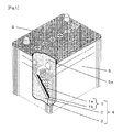
- FIG. 1 A schematic general view of a lead acid battery of the present invention.
- FIG. 1 is a schematic general view of a lead acid battery of the present invention
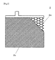
- FIG. 2 is an illustration of an example of a negative electrode plate, which is an essential part of the lead acid battery of the present invention
- a plurality of electrode plate groups 4 each including a positive electrode plate 1 , a negative electrode plate 2 , and a separator 3 interposed therebetween are placed in a battery container 5 which has a plurality of cell chambers 5 a and contains an electrolyte (not shown).
- the opening of the battery container 5 is sealed with a lid 6 .
- the positive electrode plate 1 includes a positive electrode grid 1 a and a positive electrode active material 1 b.
- the negative electrode plate 2 includes a negative electrode grid 2 a and a negative electrode active material 2 b.
- the present invention includes two features. The first is that a ratio P/N of mass P of the positive electrode active material 1 b to mass N of the negative electrode active material 2 b is 1.25 or more and 1.65 or less. The second is that the negative electrode grid. 2 a contains bismuth in an amount of 1 ppm or more and 300 ppm or less.
- the present invention employs the above-described two features.
- the first feature is that the ratio P/N of mass P of the positive electrode active material 1 b to mass N of the negative electrode active material 2 b is 1.25 or more and 1.65 or less. Conventionally, the ratio P/N has been adjusted to below 1.25, thereby to ensure charging performance, while maintaining a predetermined battery capacity.
- the SOC When, however, charging is performed in the control as above in which the SOC is kept relatively low (a full charge is not reached), although improvement in the charging efficiency can be expected because no overcharge occurs, the SOC significantly drops during frequently repeated charge and discharge in the idling stop control, and this leads to a deterioration mode in which the positive electrode active material 1 b softens and separates from the positive electrode plate 1 .
- the charge/discharge reaction at the positive electrode plate 1 can proceed homogeneously. Therefore, even though the battery is configured to have the ratio P/N being 1.25 or more and 1.43 or less, i.e., configured such that, upon the loss of reaction homogeneity at the positive electrode plate 1 , the battery reaches a SOC region where the positive electrode active material 1 b softens locally, it can be controlled so as not to reach the SOC region where the positive electrode active material 1 b softens locally.
- the second feature is that bismuth is contained in the negative electrode grid 2 a in an amount of 1 ppm or more and 300 ppm or less.
- the presence of an appropriate amount of bismuth in the negative electrode grid 2 a decreases the hydrogen overvoltage, and hydrogen gas tends to be generated even though the SOC is below 100%, allowng the diffusion of the electrolyte to easily occur. This, as a result, can eliminate the stratification.
- the present invention configured to include the above-described two features, it is possible to provide a lead acid battery that can sufficiently exert its life characteristics even charged and discharged repeatedly under the condition where the SOC is below 100%.
- the effect of the present invention is remarkable in a lead acid battery for car starter, more specifically, in a liquid-type lead acid battery in which the liquid level of the electrolyte is above the top of the electrode plate groups 4 .
- the P/N ratio of mass P of the positive electrode active material 1 b to mass N of the negative electrode active material 2 b, and the mass ratio of the carbon included in the negative electrode active material 2 b are defined, supposing that the SOC is 100%.
- the mass ratio in the present invention refers to a mass ratio in a lead acid battery which is intentionally charged until the SOC reaches 100% (for example, by using another power supply) before mounted in a car or in an initial state for car starter.
- a D26L-size lead acid battery specified in JIS D5301 was fabricated in the present Example as a lead acid battery 1 having cell chambers 5 a each accommodating seven positive electrode plates 1 and eight negative electrode plates 2 , with the negative electrode plates 2 each placed inside a bag-shaped separator 3 made of polyethylene.
- the positive electrode plate 1 was obtained by kneading a lead oxide powder with sulfuric acid and purified water, to prepare a precursor paste of a positive electrode active material 1 b, and filling the paste into a positive electrode grid 1 a (expanded grid) made of a lead alloy sheet (thickness: 1.1 mm) containing calcium.
- the negative electrode plate 2 was obtained by: adding carbon and an organic additive to a lead oxide powder, and kneading the powder with sulfuric acid and purified water, to prepare a precursor paste of a negative electrode active material 2 b; and filling the paste into a negative electrode grid 2 a (expanded grid) made of a lead alloy sheet (thickness: 1.1 mm) containing calcium and, depending on the condition, bismuth.
- the mass ratio of the bismuth contained in the negative electrode grid 2 a was varied as shown in Table 1.
- the mass ratio of the carbon occupying the negative electrode active material 2 b, and the P/N ratio of mass P of the positive electrode active material 1 b to mass N of the negative electrode active material 2 b were also varied as shown in Table 1, with the SOC adjusted to 100%.
- batteries B-1 to B-9 Comparison was made among batteries B-1 to B-9.
- Batteries C-1 to C-5 were configured such that, with the ratio P/N fixed at 1.25 and the amount of bismuth in the negative electrode grid 2 a fixed at 150 ppm, the amount of carbon contained in the negative electrode active material 2 b was varied from 0.05 mass % to 0.50 mass %.
- Batteries D-1 to D-5 were configured in the same manner as Batteries C-1 to C-5, respectively, except that the ratio P/N was fixed at 1.34.
- Batteries E-1 to E-5 were configured in the same manner as Batteries C-1 to C-5, respectively, except that the ratio P/N was fixed at 1.43.
- Batteries F-1 to F-5 were configured in the same manner as Batteries C-1 to C-5, respectively, except that the ratio P/N was fixed at 1.45. Comparison was made among these batteries.
- the ratio P/N is within the range of 1.25 to 1.43. This is presumably for the following reason.
- the ratio P/N is 1.25 or more and 1.43 or less, upon the loss of reaction homogeneity at the positive electrode plate 1 , the battery reaches a SOC region where the positive electrode active material 1 b softens locally. Within this range, the effect obtained by adding an appropriate amount of carbon in the negative electrode active material 2 b becomes remarkable.
- the ratio P/N exceeds 1.43, the battery can remain relatively far away from the SOC region where the positive electrode active material 1 b softens locally.
- the positive electrode rid 1 a may contain bismuth in an amount of 1 ppm or more and 300 ppm or less.
- the present invention is useful in a lead acid battery to be mounted in cars equipped with idling stop system.
Landscapes
- Chemical & Material Sciences (AREA)
- Chemical Kinetics & Catalysis (AREA)
- Electrochemistry (AREA)
- General Chemical & Material Sciences (AREA)
- Engineering & Computer Science (AREA)
- Manufacturing & Machinery (AREA)
- Materials Engineering (AREA)
- Battery Electrode And Active Subsutance (AREA)
- Secondary Cells (AREA)
- Cell Electrode Carriers And Collectors (AREA)
Abstract
A lead acid battery including: a positive electrode plate including a positive electrode grid and a positive electrode active material; a negative electrode plate including a negative electrode grid and a negative electrode active material; an electrode plate group including the positive electrode plate, the negative electrode plate, and a separator interposed between the positive electrode plate and the negative electrode plate; a battery container including a plurality of cell chambers each accommodating the electrode plate group and an electrolyte; and a lid sealing an opening of the battery container. A ratio P/N of mass P of the positive electrode active material to mass N of the negative electrode active material is 1.25 or more and 1.65 or less. The negative electrode grid contains bismuth in an amount of 1 ppm or more and 300 ppm or less.
Description
The present invention relates to a lead acid battery for car starter.
Among lead acid car starter batteries, a lead acid battery to be mounted in cars equipped with idling stop system is supposed to be deeply discharged to a relatively low state-of-charge (SOC) region, and therefore, required to have durability against repeated deep discharge. Patent Literature 1 discloses a technique of optimizing the mass ratio between positive and negative electrode active materials, on the basis of the results of cycle life test conducted after batteries are overdischarged. Patent Literature 2, in order to improve the cycle life characteristics under more practical idling stop conditions, discloses likewise a technique of optimizing the mass ratio between positive and negative electrode active materials. The optimum range of the P/N ratio of mass P of positive electrode active material to mass N of negative electrode active material is from 0.77 to 1.43 in Patent Literature 1, and from 0.91 to 1.43 in Patent Literature 2.
- [PTL 1] Japanese Laid-Open Patent Publication No. 2006-114417
- [PTL 2] Japanese Patent Publication No. 5587523
In recent years, cars equipped with idling stop system have been getting more and more popular, and in association therewith, there occur some cases where the lead acid battery mounted in those cars is operated under more severe conditions for the battery than those as originally assumed at the time of development. Under such circumstances, it is often observed that the cycle life characteristics cannot be sufficiently exerted even by employing the techniques of Patent Literatures 1 and 2, when the battery is actually car-mounted and subjected to repeated deep discharge.
The present invention is made in view of the above problems, and aims to provide a highly reliable lead acid battery that can sufficiently exert its cycle life characteristics, even when operated under comparatively severe conditions of idling stop control.
One aspect of the present invention relates to a lead acid battery including: a positive electrode plate including a positive electrode grid and a positive electrode active material; a negative electrode plate including a negative electrode grid and a negative electrode active material; an electrode plate group including the positive electrode plate, the negative electrode plate, and a separator interposed between the positive electrode plate and the negative electrode plate; a battery container including a plurality of cell chambers each accommodating the electrode plate group and an electrolyte; and a lid sealing an opening of the battery container. A ratio P/N of mass P of the positive electrode active material to mass N of the negative electrode active material is 1.25 or more and 1.65 or less. The negative electrode grid contains bismuth in an amount of 1 ppm or more and 300 ppm or less.
In a preferable embodiment, the ratio P/N is more than 1.43 and 1.65 or less.
In a preferable embodiment, the ratio P/N is 1.25 or more and 1.43 or less, and the negative electrode active material contains carbon in an amount of 0.10 mass % or more and 0.45 mass % or less.
In a preferable embodiment, a liquid level of the electrolyte is above a top of the electrode plate group.
According to the present invention, it is possible to provide a highly reliable lead acid battery that can sufficiently exert its cycle life characteristics, even when operated under comparatively severe conditions of idling stop control.
An embodiment of the present invention is described below, with reference to drawings.
The present invention includes two features. The first is that a ratio P/N of mass P of the positive electrode active material 1 b to mass N of the negative electrode active material 2 b is 1.25 or more and 1.65 or less. The second is that the negative electrode grid. 2 a contains bismuth in an amount of 1 ppm or more and 300 ppm or less.
As the problem associated with idling stop control, Patent Literature 1 envisages that the lead acid battery is overdischarged, and Patent Literature 2 envisages that the lead acid battery is subjected to repeated quick charge and comparatively deep discharge. On the other hand, among the cars equipped with idling stop system, an increasing number of them have been employing a control method of generating a regenerative current at the time of braking and the like and charging the lead acid battery with the regenerative current. In order to achieve more efficient charging with the regenerated current, it is desirable to keep the SOC of the lead acid battery relatively low (so as not to be fully charged). Under such circumstances, even by employing the configurations of the lead acid battery as disclosed in Patent Literatures 1 and 2, which are optimized assuming a control to charge the battery to the full even for a short moment, satisfactory battery performance cannot be exerted.
Specically, as the battery is charged and discharged repeatedly under the condition where the SOC is below 100%, a phenomenon called acid stratification occurs, i.e., the sulfate ion concentration in the electrolyte becomes smaller in the upper layer portion than in the lower layer portion. When this occurs, in the upper layer portion where the sulfate ion concentration is relatively depleted, lead sulfate as a discharge product is unlikely to be produced (discharge is difficult to proceed). On the other hand, in the lower layer portion where the sulfate ion concentration is relatively in excess, sulfate ions are unlikely to be dissociated from the lead sulfate (charge is difficult to proceed). Due to this unbalance, the lead sulfate present in excess in the lower layer portion deposits, slowing down the discharge reaction as a whole. This results in deterioration in cycle life characteristics. The stratification is eliminated when the electrolyte is agitated by the gas generated through hydrolysis of electrolyte (gas generation) that occurs in the terminal stage of charging. Under the condition where the SOC is intentionally controlled to below 100%, however, charging cannot proceed to the terminal stage, and the above effect cannot be expected.
To solve this problem, the present invention employs the above-described two features.
The first feature is that the ratio P/N of mass P of the positive electrode active material 1 b to mass N of the negative electrode active material 2 b is 1.25 or more and 1.65 or less. Conventionally, the ratio P/N has been adjusted to below 1.25, thereby to ensure charging performance, while maintaining a predetermined battery capacity. When, however, charging is performed in the control as above in which the SOC is kept relatively low (a full charge is not reached), although improvement in the charging efficiency can be expected because no overcharge occurs, the SOC significantly drops during frequently repeated charge and discharge in the idling stop control, and this leads to a deterioration mode in which the positive electrode active material 1 b softens and separates from the positive electrode plate 1. Dealing with this new charging control method requires a new design concept: to significantly increase the amount of the positive electrode active material 1 b, relative to the negative electrode active material 2 b, so that the exposure of the positive electrode active material 1 b to a low SOC region can be avoided, and thus the separation of the positive electrode active material, due to softening, from the positive electrode plate 1 can be prevented. As a result of intensive studies, the inventors have found that this effect becomes remarkable by setting the ratio P/N to 1.25 or more. Setting the ratio P/N to above 1.65, however, leads to insufficient charging due to the lack of the negative electrode active material 2 b, resulting conversely in deterioration in cycle life characteristics.
Although the above effect obtained by the first feature is remarkable when the ratio P/N is above 1.43, it can also be remarkable when the ratio P/N is 1.25 or more and 1.43 or less, by including carbon in the negative electrode active material 2 b in an amount of 0.10 mass % or more and 0.45 mass % or less. Due to the carbon which does not get involved in charge and discharge and is distributed appropriately on the surface of the negative electrode plate 2, the gas generation through hydrolysis can be facilitated, in parallel with the charging reaction. This, in synergy with the effect obtained by adding an appropriate amount of bismuth to the negative electrode grid 2 a, can more vigorously agitate the electrolyte, promoting the elimination of the stratification. As a result, the charge/discharge reaction at the positive electrode plate 1 can proceed homogeneously. Therefore, even though the battery is configured to have the ratio P/N being 1.25 or more and 1.43 or less, i.e., configured such that, upon the loss of reaction homogeneity at the positive electrode plate 1, the battery reaches a SOC region where the positive electrode active material 1 b softens locally, it can be controlled so as not to reach the SOC region where the positive electrode active material 1 b softens locally. It is to be noted that when the amount of the carbon contained in the negative electrode active material 2 b is below 0.10 mass %, the above effect is not sufficient; and when above 0.45 mass %, hydrolysis proceeds somewhat excessively, and the amount of electrolyte is reduced, resulting in a slight deterioration in the cycle life characteristics.
The second feature is that bismuth is contained in the negative electrode grid 2 a in an amount of 1 ppm or more and 300 ppm or less. The presence of an appropriate amount of bismuth in the negative electrode grid 2 a decreases the hydrogen overvoltage, and hydrogen gas tends to be generated even though the SOC is below 100%, allowng the diffusion of the electrolyte to easily occur. This, as a result, can eliminate the stratification. In order to obtain this effect, it is necessary to include bismuth in the negative electrode gird 2 a in an amount of 1 ppm or more. When the amount exceeds 300 ppm, however, the hydrogen overvoltage will be decreased too much, and the hydrolysis of electrolyte occurs excessively, reducing the electrolyte significantly. This accelerates the corrosion of tab-shape current collecting portions (tabs) exposed out of the electrolyte of the positive and negative electrode plates 1 and 2, resulting conversely in deterioration in the cycle life characteristics.
According to the present invention configured to include the above-described two features, it is possible to provide a lead acid battery that can sufficiently exert its life characteristics even charged and discharged repeatedly under the condition where the SOC is below 100%.
The effect of the present invention is remarkable in a lead acid battery for car starter, more specifically, in a liquid-type lead acid battery in which the liquid level of the electrolyte is above the top of the electrode plate groups 4.
In the present invention, the P/N ratio of mass P of the positive electrode active material 1 b to mass N of the negative electrode active material 2 b, and the mass ratio of the carbon included in the negative electrode active material 2 b are defined, supposing that the SOC is 100%. More specifically, the mass ratio in the present invention refers to a mass ratio in a lead acid battery which is intentionally charged until the SOC reaches 100% (for example, by using another power supply) before mounted in a car or in an initial state for car starter.
The effects of the present invention will now be described below with reference to Examples.
(1) Fabrication of Lead Acid Battery
A D26L-size lead acid battery specified in JIS D5301 was fabricated in the present Example as a lead acid battery 1 having cell chambers 5 a each accommodating seven positive electrode plates 1 and eight negative electrode plates 2, with the negative electrode plates 2 each placed inside a bag-shaped separator 3 made of polyethylene.
The positive electrode plate 1 was obtained by kneading a lead oxide powder with sulfuric acid and purified water, to prepare a precursor paste of a positive electrode active material 1 b, and filling the paste into a positive electrode grid 1 a (expanded grid) made of a lead alloy sheet (thickness: 1.1 mm) containing calcium.
The negative electrode plate 2 was obtained by: adding carbon and an organic additive to a lead oxide powder, and kneading the powder with sulfuric acid and purified water, to prepare a precursor paste of a negative electrode active material 2 b; and filling the paste into a negative electrode grid 2 a (expanded grid) made of a lead alloy sheet (thickness: 1.1 mm) containing calcium and, depending on the condition, bismuth.
The mass ratio of the bismuth contained in the negative electrode grid 2 a was varied as shown in Table 1. Likewise, the mass ratio of the carbon occupying the negative electrode active material 2 b, and the P/N ratio of mass P of the positive electrode active material 1 b to mass N of the negative electrode active material 2 b were also varied as shown in Table 1, with the SOC adjusted to 100%.
The obtained positive and negative electrode plates 1 and 2 were aged and dried. Afterwards, the negative electrode plates 2 were each placed inside the bag-shaped separator 3 made of polyethylene, and stacked on the positive electrode plates 2 alternately one on another, to obtain an electrode plate group 4 comprising seven positive electrode plates 1 and eight negative electrode plates 2 stacked alternately one on another with the separator 3 therebetween. The electrode plate group 4 was placed into each of six cell chambers 5 a divided by a partition, and six cells were directly connected to each other. Subsequently, an electrolyte comprising a dilute sulfuric acid having a density of 1.28 g/cm3 was injected to perform chemical formation. A lead acid battery was thus produced.
(2) Life Characteristics
The fabricated lead acid batteries, after the SOC was adjusted to 90%, were evaluated by following the steps below.
- A. Subjecting battery to discharging at 45 A for 59 seconds
- B. Subjecting battery to discharging at 300 A for 1 second
- C. Subjecting battery to 14.0 V constant-voltage charging for 60 seconds with maximum current limited to 100 A
- D. After 3600-times repetition of a charge-discharge cycle consisting of A, B and C performed in this order, subjecting battery to refresh charging, i.e., 14.0 V constant-voltage charging for 30 minutes with maximum current limited to 50 A
- E. After allowing battery to stand for 48 hours, adjusting SOC to 90% again.
The above A to B steps were repeated, and when the discharge voltage dropped below 7.2 V, the battery was judged as having reached the end of the life. Based on this judgment, it was decided every 3600 cycles whether or not to continue the test. The number of cycles performed until it was decided not to continue is shown in Table 1, together with the constitution conditions.
| TABLE 1 | ||||||
| Carbon in | ||||||
| Bismuth | negative | |||||
| in negative | electrode | |||||
| electrode | active | |||||
| Ratio | grid | material | Cycle life | |||
| Battery | P/N | (ppm) | (mass %) | characteristics | ||
| A-1 | 1.21 | 150 | 0.05 | 46,800 | ||
| A-2 | 1.25 | 150 | 0.05 | 68,400 | ||
| A-3 | 1.34 | 150 | 0.05 | 72,000 | ||
| A-4 | 1.43 | 150 | 0.05 | 72,000 | ||
| A-5 | 1.45 | 150 | 0.05 | 82,800 | ||
| A-6 | 1.55 | 150 | 0.05 | 100,800 | ||
| A-7 | 1.65 | 150 | 0.05 | 79,200 | ||
| A-8 | 1.69 | 150 | 0.05 | 50,400 | ||
| B-1 | 1.55 | 0.5 | 0.05 | 50,400 | ||
| B-2 | 1.55 | 1 | 0.05 | 68,400 | ||
| B-3 | 1.55 | 10 | 0.05 | 79,200 | ||
| B-4 | 1.55 | 50 | 0.05 | 93,500 | ||
| B-5 | 1.55 | 150 | 0.05 | 100,800 | ||
| B-6 | 1.55 | 200 | 0.05 | 93,600 | ||
| B-7 | 1.55 | 250 | 0.05 | 82,800 | ||
| B-8 | 1.55 | 300 | 0.05 | 72,000 | ||
| B-9 | 1.55 | 330 | 0.05 | 50,400 | ||
| C-1 | 1.25 | 150 | 0.05 | 68,400 | ||
| C-2 | 1.25 | 150 | 0.10 | 79,200 | ||
| C-3 | 1.25 | 150 | 0.30 | 93,600 | ||
| C-4 | 1.25 | 150 | 0.45 | 79,200 | ||
| C-5 | 1.25 | 150 | 0.50 | 72,000 | ||
| D-1 | 1.34 | 150 | 0.05 | 72,000 | ||
| D-2 | 1.34 | 150 | 0.10 | 82,800 | ||
| D-3 | 1.34 | 150 | 0.30 | 93,600 | ||
| D-4 | 1.34 | 150 | 0.45 | 82,800 | ||
| D-5 | 1.34 | 150 | 0.50 | 72,000 | ||
| E-1 | 1.43 | 150 | 0.05 | 72,000 | ||
| E-2 | 1.43 | 150 | 0.10 | 82,800 | ||
| E-3 | 1.43 | 150 | 0.30 | 93,600 | ||
| E-4 | 1.43 | 150 | 0.45 | 82,800 | ||
| F-5 | 1.43 | 150 | 0.50 | 68,400 | ||
| F-1 | 1.45 | 150 | 0.05 | 82,800 | ||
| F-2 | 1.45 | 150 | 0.10 | 90,000 | ||
| F-3 | 1.45 | 150 | 0.30 | 93,600 | ||
| F-4 | 1.45 | 150 | 0.45 | 86,400 | ||
| F-5 | 1.45 | 150 | 0.50 | 79,200 | ||
Comparison was made among batteries A-1 to A-8. Battery A-1 having a ratio P/N below 1.25 and battery A-8 having a ratio P/N above 1.65 were both inferior in the cycle life characteristics. These batteries were disassembled, and it was observed that: in battery A-1, the positive electrode active material 1 b softened and separated; and in battery A-8, charging did not proceed sufficiently. This shows that the ratio P/N is appropriately 1.25 or more and 1.65 or less, and preferably more than 1.43 and 1.65 or less.
Comparison was made among batteries B-1 to B-9. Battery B-1 in which the amount of bismuth contained in the negative electrode grid 2 a was less than 1 ppm, and battery B-9 in which the amount of bismuth was more than 300 ppm were both inferior in the cycle life characteristics. These batteries were disassembled, and it was observed that: in battery B-1, the stratification of the electrolyte occurred severely; and in battery B-9, the electrolyte was extremely reduced. This shows that the amount of bismuth contained in the negative electrode grid 2 a is appropriately 1 ppm or more and 300 ppm or less.
Having considered the evaluation results of batteries A-1 to A-8, along with those of batteries B-1 to B-9, it would be understood that both the ratio P/N and the amount of bismuth contained in the negative electrode grid 2 a should be adjusted within the appropriate range.
Batteries C-1 to C-5 were configured such that, with the ratio P/N fixed at 1.25 and the amount of bismuth in the negative electrode grid 2 a fixed at 150 ppm, the amount of carbon contained in the negative electrode active material 2 b was varied from 0.05 mass % to 0.50 mass %. Batteries D-1 to D-5 were configured in the same manner as Batteries C-1 to C-5, respectively, except that the ratio P/N was fixed at 1.34. Batteries E-1 to E-5 were configured in the same manner as Batteries C-1 to C-5, respectively, except that the ratio P/N was fixed at 1.43. Batteries F-1 to F-5 were configured in the same manner as Batteries C-1 to C-5, respectively, except that the ratio P/N was fixed at 1.45. Comparison was made among these batteries.
When the ratio P/N is within the range of 1.25 to 1.43, containing carbon in the negative electrode active material 2 b in an amount of 0.10 mass % or more and 0.45 mass % or less resulted in better cycle life characteristics than containing carbon in the negative electrode active material 2 b in the amount of 0.05 mass %. This is presumably because the addition of an appropriate amount of carbon facilitated the gas generation through hydrolysis, and due to this, the stratification was eliminated. Increasing the amount of carbon contained in the negative electrode active material 2 b to greater than 0.45 mass %, however, did not result in better cycle life characteristics. This is presumably because hydrolysis proceeded somewhat excessively, tending to reduce the electrolyte.
The above tendency is uniquely observed when the ratio P/N is within the range of 1.25 to 1.43. This is presumably for the following reason. When the ratio P/N is 1.25 or more and 1.43 or less, upon the loss of reaction homogeneity at the positive electrode plate 1, the battery reaches a SOC region where the positive electrode active material 1 b softens locally. Within this range, the effect obtained by adding an appropriate amount of carbon in the negative electrode active material 2 b becomes remarkable. When the ratio P/N exceeds 1.43, the battery can remain relatively far away from the SOC region where the positive electrode active material 1 b softens locally.
Although the present invention was described above by way of preferable embodiments, they should not be construed as limiting the scope of the invention, and various variations are possible. For example, the positive electrode rid 1 a, like the negative electrode grid 2 a, may contain bismuth in an amount of 1 ppm or more and 300 ppm or less.
The present invention is useful in a lead acid battery to be mounted in cars equipped with idling stop system.
- 1: positive electrode plate
- 1 a: positive electrode grid
- 1 b: positive electrode active material
- 2: negative electrode plate
- 2 a: negative electrode grid
- 2 b: negative electrode active material
- 3: separator
- 4: electrode plate group
- 5: battery container
- 5 a: cell chamber
- 6: lid
Claims (4)
1. A lead acid battery comprising:
a positive electrode plate including a positive electrode grid and a positive electrode active material;
a negative electrode plate including a negative electrode grid and a negative electrode active material;
an electrode plate group including the positive electrode plate, the negative electrode plate, and a separator interposed between the positive electrode plate and the negative electrode plate;
a battery container including a plurality of cell chambers each accommodating the electrode plate group and an electrolyte; and
a lid sealing an opening of the battery container;
a ratio P/N of mass P of the positive electrode active material to mass N of the negative electrode active material being 1.25 or more and 1.65 or less,
the negative electrode grid containing bismuth in an amount of 1 ppm or more and 300 ppm or less.
2. The lead acid battery of claim 1 , wherein the ratio P/N is more than 1.43 and 1.65 or less.
3. The lead acid battery of claim 1 , wherein the ratio P/N is 1.25 or more and 1.43 or less, and the negative electrode active material contains carbon in an amount of 0.10 mass % or more and 0.45 mass % or less.
4. The lead acid battery of claim 1 , wherein a liquid level of the electrolyte is above a top of the electrode plate group.
Applications Claiming Priority (3)
| Application Number | Priority Date | Filing Date | Title |
|---|---|---|---|
| JP2015024894 | 2015-02-12 | ||
| JP2015-024894 | 2015-02-12 | ||
| PCT/JP2015/006024 WO2016129021A1 (en) | 2015-02-12 | 2015-12-04 | Lead storage battery |
Publications (2)
| Publication Number | Publication Date |
|---|---|
| US20180026310A1 US20180026310A1 (en) | 2018-01-25 |
| US10205193B2 true US10205193B2 (en) | 2019-02-12 |
Family
ID=56614375
Family Applications (1)
| Application Number | Title | Priority Date | Filing Date |
|---|---|---|---|
| US15/549,867 Active US10205193B2 (en) | 2015-02-12 | 2015-12-04 | Lead acid battery |
Country Status (5)
| Country | Link |
|---|---|
| US (1) | US10205193B2 (en) |
| JP (1) | JP6575536B2 (en) |
| CN (1) | CN107112598B (en) |
| DE (1) | DE112015006162B4 (en) |
| WO (1) | WO2016129021A1 (en) |
Cited By (1)
| Publication number | Priority date | Publication date | Assignee | Title |
|---|---|---|---|---|
| US20230020146A1 (en) * | 2019-12-06 | 2023-01-19 | Gs Yuasa International Ltd. | Control apparatus, degradation estimating system, control method, and computer program |
Families Citing this family (3)
| Publication number | Priority date | Publication date | Assignee | Title |
|---|---|---|---|---|
| CN109585939B (en) * | 2018-10-30 | 2021-10-29 | 浙江平湖华龙实业股份有限公司 | High-performance storage battery |
| CN113540578B (en) * | 2021-07-16 | 2022-11-29 | 远景动力技术(江苏)有限公司 | Battery cell preparation and optimization method and battery cell |
| WO2024071017A1 (en) * | 2022-09-27 | 2024-04-04 | 株式会社Gsユアサ | Lead acid storage battery |
Citations (14)
| Publication number | Priority date | Publication date | Assignee | Title |
|---|---|---|---|---|
| JPS61203568A (en) | 1985-03-05 | 1986-09-09 | Yuasa Battery Co Ltd | Lead storage battery |
| JPH04296464A (en) | 1991-03-26 | 1992-10-20 | Shin Kobe Electric Mach Co Ltd | Sealed-type lead-acid battery |
| JP2004087248A (en) | 2002-08-26 | 2004-03-18 | Japan Storage Battery Co Ltd | Lead storage battery |
| US20040142243A1 (en) * | 2002-04-18 | 2004-07-22 | The Furukawa Battery Co., Ltd. | Lead-based alloy for lead-acid battery, substrate for lead-acid battery and lead-acid battery |
| US20040187986A1 (en) | 2002-08-13 | 2004-09-30 | Johnson Controls Technology Company | Alloy for battery grids |
| JP2006114417A (en) | 2004-10-18 | 2006-04-27 | Matsushita Electric Ind Co Ltd | Lead acid battery |
| JP2006294290A (en) | 2005-04-06 | 2006-10-26 | Matsushita Electric Ind Co Ltd | Lead acid battery |
| US20080233482A1 (en) * | 2007-03-20 | 2008-09-25 | Northstar Battery Company Llc | Lead-Tin-Silver-Bismuth Containing Alloy for Positive Grid of Lead Acid Batteries |
| US20090061290A1 (en) | 2005-04-06 | 2009-03-05 | Seiji Anzai | Lead-Acid Rechargeable Battery |
| JP2010192162A (en) | 2009-02-16 | 2010-09-02 | Gs Yuasa Corp | Lead-acid storage battery |
| WO2012043331A1 (en) | 2010-09-29 | 2012-04-05 | 株式会社Gsユアサ | Lead-acid storage battery and idling-stop vehicle whereupon said lead-acid storage battery is mounted |
| JP2013073716A (en) | 2011-09-27 | 2013-04-22 | Gs Yuasa Corp | Lead acid battery |
| JP5587523B1 (en) | 2012-12-21 | 2014-09-10 | パナソニック株式会社 | Lead acid battery |
| CN104067436A (en) | 2012-01-31 | 2014-09-24 | 松下电器产业株式会社 | Lead-acid battery |
Family Cites Families (3)
| Publication number | Priority date | Publication date | Assignee | Title |
|---|---|---|---|---|
| JP3936157B2 (en) | 2001-08-07 | 2007-06-27 | 古河電池株式会社 | Manufacturing method for sealed lead-acid batteries |
| CN102938465B (en) * | 2012-11-11 | 2015-08-19 | 骆驼集团华南蓄电池有限公司 | Lead-acid storage battery grid lead alloy |
| CN104282910A (en) | 2013-07-12 | 2015-01-14 | 苏州宝时得电动工具有限公司 | Battery |
-
2015
- 2015-12-04 JP JP2016574531A patent/JP6575536B2/en active Active
- 2015-12-04 WO PCT/JP2015/006024 patent/WO2016129021A1/en not_active Ceased
- 2015-12-04 CN CN201580073074.0A patent/CN107112598B/en active Active
- 2015-12-04 DE DE112015006162.2T patent/DE112015006162B4/en active Active
- 2015-12-04 US US15/549,867 patent/US10205193B2/en active Active
Patent Citations (15)
| Publication number | Priority date | Publication date | Assignee | Title |
|---|---|---|---|---|
| JPS61203568A (en) | 1985-03-05 | 1986-09-09 | Yuasa Battery Co Ltd | Lead storage battery |
| JPH04296464A (en) | 1991-03-26 | 1992-10-20 | Shin Kobe Electric Mach Co Ltd | Sealed-type lead-acid battery |
| US20040142243A1 (en) * | 2002-04-18 | 2004-07-22 | The Furukawa Battery Co., Ltd. | Lead-based alloy for lead-acid battery, substrate for lead-acid battery and lead-acid battery |
| US20040187986A1 (en) | 2002-08-13 | 2004-09-30 | Johnson Controls Technology Company | Alloy for battery grids |
| JP2004087248A (en) | 2002-08-26 | 2004-03-18 | Japan Storage Battery Co Ltd | Lead storage battery |
| JP2006114417A (en) | 2004-10-18 | 2006-04-27 | Matsushita Electric Ind Co Ltd | Lead acid battery |
| JP2006294290A (en) | 2005-04-06 | 2006-10-26 | Matsushita Electric Ind Co Ltd | Lead acid battery |
| US20090061290A1 (en) | 2005-04-06 | 2009-03-05 | Seiji Anzai | Lead-Acid Rechargeable Battery |
| US20080233482A1 (en) * | 2007-03-20 | 2008-09-25 | Northstar Battery Company Llc | Lead-Tin-Silver-Bismuth Containing Alloy for Positive Grid of Lead Acid Batteries |
| JP2010192162A (en) | 2009-02-16 | 2010-09-02 | Gs Yuasa Corp | Lead-acid storage battery |
| WO2012043331A1 (en) | 2010-09-29 | 2012-04-05 | 株式会社Gsユアサ | Lead-acid storage battery and idling-stop vehicle whereupon said lead-acid storage battery is mounted |
| JP2013073716A (en) | 2011-09-27 | 2013-04-22 | Gs Yuasa Corp | Lead acid battery |
| CN104067436A (en) | 2012-01-31 | 2014-09-24 | 松下电器产业株式会社 | Lead-acid battery |
| US20140329148A1 (en) | 2012-01-31 | 2014-11-06 | Panasonic Corporation | Lead-acid battery |
| JP5587523B1 (en) | 2012-12-21 | 2014-09-10 | パナソニック株式会社 | Lead acid battery |
Non-Patent Citations (2)
| Title |
|---|
| Chinese Office Action dated Nov. 27, 2018 issued in the corresponding Chinese Patent Application No. 201580073074.0. |
| International Search Report dated Mar. 1, 2016 filed in PCT/JP2015/006024. |
Cited By (1)
| Publication number | Priority date | Publication date | Assignee | Title |
|---|---|---|---|---|
| US20230020146A1 (en) * | 2019-12-06 | 2023-01-19 | Gs Yuasa International Ltd. | Control apparatus, degradation estimating system, control method, and computer program |
Also Published As
| Publication number | Publication date |
|---|---|
| DE112015006162T5 (en) | 2017-11-02 |
| WO2016129021A1 (en) | 2016-08-18 |
| JPWO2016129021A1 (en) | 2017-12-21 |
| CN107112598A (en) | 2017-08-29 |
| DE112015006162B4 (en) | 2026-05-07 |
| CN107112598B (en) | 2019-12-10 |
| US20180026310A1 (en) | 2018-01-25 |
| JP6575536B2 (en) | 2019-09-18 |
Similar Documents
| Publication | Publication Date | Title |
|---|---|---|
| US20110027653A1 (en) | Negative plate for lead acid battery | |
| US10205193B2 (en) | Lead acid battery | |
| US9570779B2 (en) | Flooded lead-acid battery | |
| US20110250500A1 (en) | Positive active material for a lead-acid battery | |
| JP6977770B2 (en) | Liquid lead-acid battery | |
| WO2014162674A1 (en) | Lead acid storage battery | |
| JP6045329B2 (en) | Lead acid battery | |
| EP3352285B1 (en) | Lead storage battery | |
| JP2008243493A (en) | Lead acid storage battery | |
| JP4771678B2 (en) | Open-type lead-acid battery for automobiles | |
| US3170819A (en) | Electric battery | |
| US20060154148A1 (en) | Control valve type lead battery | |
| KR101786393B1 (en) | Electrolyte composition of lead storage battery and lead storage battery using the same | |
| JP7128482B2 (en) | lead acid battery | |
| US20180205072A1 (en) | Lead acid storage battery | |
| JP5573785B2 (en) | Lead acid battery | |
| JP6996274B2 (en) | Lead-acid battery | |
| WO2011077640A1 (en) | Valve-regulated lead acid battery | |
| JP6956698B2 (en) | Liquid lead-acid battery | |
| JP2016152192A (en) | Lead-acid battery | |
| JP2025097665A (en) | Lead-acid battery for auxiliary machine | |
| JP2024171483A (en) | Lead-acid battery | |
| JP5754607B2 (en) | Lead acid battery | |
| JP2022138753A (en) | Lead-acid battery | |
| JP2009087638A (en) | Control valve type lead acid battery |
Legal Events
| Date | Code | Title | Description |
|---|---|---|---|
| AS | Assignment |
Owner name: GS YUASA INTERNATIONAL LTD., JAPAN Free format text: ASSIGNMENT OF ASSIGNORS INTEREST;ASSIGNORS:IZUMI, KENJI;SATO, YOSHINOBU;OGASAWARA, ETSUKO;AND OTHERS;SIGNING DATES FROM 20170627 TO 20170628;REEL/FRAME:043247/0586 |
|
| STCF | Information on status: patent grant |
Free format text: PATENTED CASE |
|
| MAFP | Maintenance fee payment |
Free format text: PAYMENT OF MAINTENANCE FEE, 4TH YEAR, LARGE ENTITY (ORIGINAL EVENT CODE: M1551); ENTITY STATUS OF PATENT OWNER: LARGE ENTITY Year of fee payment: 4 |