US10052253B2 - Hand-propelled vehicle - Google Patents
Hand-propelled vehicle Download PDFInfo
- Publication number
- US10052253B2 US10052253B2 US15/185,306 US201615185306A US10052253B2 US 10052253 B2 US10052253 B2 US 10052253B2 US 201615185306 A US201615185306 A US 201615185306A US 10052253 B2 US10052253 B2 US 10052253B2
- Authority
- US
- United States
- Prior art keywords
- inclination angle
- main body
- inclination
- unit
- angle
- Prior art date
- Legal status (The legal status is an assumption and is not a legal conclusion. Google has not performed a legal analysis and makes no representation as to the accuracy of the status listed.)
- Expired - Fee Related, expires
Links
- 230000001133 acceleration Effects 0.000 claims description 26
- 230000007423 decrease Effects 0.000 description 7
- 238000010586 diagram Methods 0.000 description 6
- 230000006399 behavior Effects 0.000 description 4
- 210000000245 forearm Anatomy 0.000 description 3
- 230000006870 function Effects 0.000 description 3
- 238000000034 method Methods 0.000 description 3
- 230000004044 response Effects 0.000 description 2
- 239000000758 substrate Substances 0.000 description 2
- XUIMIQQOPSSXEZ-UHFFFAOYSA-N Silicon Chemical compound [Si] XUIMIQQOPSSXEZ-UHFFFAOYSA-N 0.000 description 1
- 238000013459 approach Methods 0.000 description 1
- 230000008878 coupling Effects 0.000 description 1
- 238000010168 coupling process Methods 0.000 description 1
- 238000005859 coupling reaction Methods 0.000 description 1
- 238000001514 detection method Methods 0.000 description 1
- 238000006073 displacement reaction Methods 0.000 description 1
- 229910052710 silicon Inorganic materials 0.000 description 1
- 239000010703 silicon Substances 0.000 description 1
Images


Classifications
-
- A—HUMAN NECESSITIES
- A61—MEDICAL OR VETERINARY SCIENCE; HYGIENE
- A61H—PHYSICAL THERAPY APPARATUS, e.g. DEVICES FOR LOCATING OR STIMULATING REFLEX POINTS IN THE BODY; ARTIFICIAL RESPIRATION; MASSAGE; BATHING DEVICES FOR SPECIAL THERAPEUTIC OR HYGIENIC PURPOSES OR SPECIFIC PARTS OF THE BODY
- A61H3/00—Appliances for aiding patients or disabled persons to walk about
- A61H3/04—Wheeled walking aids for patients or disabled persons
- A61H2003/043—Wheeled walking aids for patients or disabled persons with a drive mechanism
-
- A—HUMAN NECESSITIES
- A61—MEDICAL OR VETERINARY SCIENCE; HYGIENE
- A61H—PHYSICAL THERAPY APPARATUS, e.g. DEVICES FOR LOCATING OR STIMULATING REFLEX POINTS IN THE BODY; ARTIFICIAL RESPIRATION; MASSAGE; BATHING DEVICES FOR SPECIAL THERAPEUTIC OR HYGIENIC PURPOSES OR SPECIFIC PARTS OF THE BODY
- A61H3/00—Appliances for aiding patients or disabled persons to walk about
- A61H3/04—Wheeled walking aids for patients or disabled persons
- A61H2003/046—Wheeled walking aids for patients or disabled persons with braking means
-
- A—HUMAN NECESSITIES
- A61—MEDICAL OR VETERINARY SCIENCE; HYGIENE
- A61H—PHYSICAL THERAPY APPARATUS, e.g. DEVICES FOR LOCATING OR STIMULATING REFLEX POINTS IN THE BODY; ARTIFICIAL RESPIRATION; MASSAGE; BATHING DEVICES FOR SPECIAL THERAPEUTIC OR HYGIENIC PURPOSES OR SPECIFIC PARTS OF THE BODY
- A61H2201/00—Characteristics of apparatus not provided for in the preceding codes
- A61H2201/01—Constructive details
- A61H2201/0192—Specific means for adjusting dimensions
-
- A—HUMAN NECESSITIES
- A61—MEDICAL OR VETERINARY SCIENCE; HYGIENE
- A61H—PHYSICAL THERAPY APPARATUS, e.g. DEVICES FOR LOCATING OR STIMULATING REFLEX POINTS IN THE BODY; ARTIFICIAL RESPIRATION; MASSAGE; BATHING DEVICES FOR SPECIAL THERAPEUTIC OR HYGIENIC PURPOSES OR SPECIFIC PARTS OF THE BODY
- A61H2201/00—Characteristics of apparatus not provided for in the preceding codes
- A61H2201/50—Control means thereof
- A61H2201/5007—Control means thereof computer controlled
-
- A—HUMAN NECESSITIES
- A61—MEDICAL OR VETERINARY SCIENCE; HYGIENE
- A61H—PHYSICAL THERAPY APPARATUS, e.g. DEVICES FOR LOCATING OR STIMULATING REFLEX POINTS IN THE BODY; ARTIFICIAL RESPIRATION; MASSAGE; BATHING DEVICES FOR SPECIAL THERAPEUTIC OR HYGIENIC PURPOSES OR SPECIFIC PARTS OF THE BODY
- A61H2201/00—Characteristics of apparatus not provided for in the preceding codes
- A61H2201/50—Control means thereof
- A61H2201/5023—Interfaces to the user
- A61H2201/5025—Activation means
- A61H2201/5028—Contact activation, i.e. activated at contact with a surface of the user to be treated
-
- A—HUMAN NECESSITIES
- A61—MEDICAL OR VETERINARY SCIENCE; HYGIENE
- A61H—PHYSICAL THERAPY APPARATUS, e.g. DEVICES FOR LOCATING OR STIMULATING REFLEX POINTS IN THE BODY; ARTIFICIAL RESPIRATION; MASSAGE; BATHING DEVICES FOR SPECIAL THERAPEUTIC OR HYGIENIC PURPOSES OR SPECIFIC PARTS OF THE BODY
- A61H2201/00—Characteristics of apparatus not provided for in the preceding codes
- A61H2201/50—Control means thereof
- A61H2201/5058—Sensors or detectors
- A61H2201/5069—Angle sensors
-
- A—HUMAN NECESSITIES
- A61—MEDICAL OR VETERINARY SCIENCE; HYGIENE
- A61H—PHYSICAL THERAPY APPARATUS, e.g. DEVICES FOR LOCATING OR STIMULATING REFLEX POINTS IN THE BODY; ARTIFICIAL RESPIRATION; MASSAGE; BATHING DEVICES FOR SPECIAL THERAPEUTIC OR HYGIENIC PURPOSES OR SPECIFIC PARTS OF THE BODY
- A61H2201/00—Characteristics of apparatus not provided for in the preceding codes
- A61H2201/50—Control means thereof
- A61H2201/5058—Sensors or detectors
- A61H2201/5079—Velocity sensors
-
- A—HUMAN NECESSITIES
- A61—MEDICAL OR VETERINARY SCIENCE; HYGIENE
- A61H—PHYSICAL THERAPY APPARATUS, e.g. DEVICES FOR LOCATING OR STIMULATING REFLEX POINTS IN THE BODY; ARTIFICIAL RESPIRATION; MASSAGE; BATHING DEVICES FOR SPECIAL THERAPEUTIC OR HYGIENIC PURPOSES OR SPECIFIC PARTS OF THE BODY
- A61H2201/00—Characteristics of apparatus not provided for in the preceding codes
- A61H2201/50—Control means thereof
- A61H2201/5058—Sensors or detectors
- A61H2201/5084—Acceleration sensors
-
- A—HUMAN NECESSITIES
- A61—MEDICAL OR VETERINARY SCIENCE; HYGIENE
- A61H—PHYSICAL THERAPY APPARATUS, e.g. DEVICES FOR LOCATING OR STIMULATING REFLEX POINTS IN THE BODY; ARTIFICIAL RESPIRATION; MASSAGE; BATHING DEVICES FOR SPECIAL THERAPEUTIC OR HYGIENIC PURPOSES OR SPECIFIC PARTS OF THE BODY
- A61H2201/00—Characteristics of apparatus not provided for in the preceding codes
- A61H2201/50—Control means thereof
- A61H2201/5058—Sensors or detectors
- A61H2201/5092—Optical sensor
Definitions
- the present disclosure relates to hand-propelled vehicles with wheels and, in particular, to a hand-propelled vehicle that drives and controls wheels.
- Patent Document 1 Previously, there were hand-propelled vehicles that assisted walking by driving and controlling wheels and performing inverted pendulum control (see, for example, Patent Document 1).
- the hand-propelled vehicle in Patent Document 1 includes a main body rotatable in a pitch direction, a support unit having a first end connected to the main body, and auxiliary wheels connected to a second end of the support unit.
- the hand-propelled vehicle can maintain the position of the main body constant by driving and controlling the wheels such that an inclination angle of the main body in the pitch direction is equal to a target inclination angle and such that an angular change is zero.
- Patent Document 1 International Publication No. 2012-114597
- the inverted pendulum control needs to detect the inclination angle of the main body in the pitch direction with respect to a vertical axis.
- the road surface is horizontal, because the vertical axis coincides with the normal to the ground road surface, the inclination angle of the main body in the pitch direction with respect to the vertical axis can be calculated by geometrical calculation using the above-described crossing angle between the main body and the support unit.
- the road surface is not horizontal, that is, on a hill, it is necessary to detect an inclination angle of the road surface in the pitch direction by an inclination sensor or the like and to make a correction to the calculated inclination angle of the main body in the pitch direction.
- the inclination sensor is required to be mounted on either the main body or the support unit. In both of the case where it is mounted on the main body and the case where it is mounted on the support unit, an output of the inclination sensor changes in response to an angular change in the main body in the pitch direction. Accordingly, it is difficult to sense the inclination angle of the road surface with high accuracy.
- the present disclosure provides a hand-propelled vehicle that employs inverted pendulum control and is capable of detecting an inclination angle of a road surface easily and with high accuracy.
- a hand-propelled vehicle includes a main body, a plurality of main wheels being rotatable and supported by the main body, a support unit coupled to a rotating shaft of each of the plurality of main wheels and being rotatable in a pitch direction (a rotational direction about an axis parallel to the rotational axis of the rotating shaft of each of the plurality of main wheels), one or more auxiliary wheels coupled to the support unit, a drive unit (e.g., a circuit) configured to drive a motor for rotating the plurality of main wheels, a control unit (e.g., CPU) configured to control the drive unit, a crossing-angle detecting unit configured to detect an angle between the main body and the support unit, and a road-surface inclination angle detecting unit mounted on the support unit and configured to detect an inclination angle of a road surface in the pitch direction.
- a drive unit e.g., a circuit
- a control unit e.g., CPU
- the control unit is configured to calculate an inclination angle of the main body in the pitch direction with respect to a vertical axis on the basis of an output of the crossing-angle detecting unit and an output of the road-surface inclination angle detecting unit and to control the drive unit such that the inclination angle of the main body in the pitch direction with respect to the vertical axis is equal to a target inclination angle of the main body in the pitch direction.
- the support unit is coupled to the rotating shaft of the main wheel in the hand-propelled vehicle in the present disclosure, in a case where the main body rotates in the pitch direction, the angle between the road surface and the support unit is maintained in parallel or at a predetermined angle. Accordingly, detecting the inclination of the support unit with respect to a horizontal direction by the inclination angle detecting unit enables directly detecting the inclination angle of the road surface. Thus, the inclination angle of the road surface can be detected easily and with high accuracy, irrespective of the inclination angle of the main body.
- the inclination angle detecting unit may include a sensor capable of detecting the inclination angle of the road surface and may include, for example, at least one or more of an inclination angle sensor, a single-axis acceleration sensor, and a multi-axis acceleration sensor.
- the crossing-angle detecting unit may include a sensor capable of detecting the angle between the main body and the support unit and may include, for example, at least one or more of a rotary encoder and a potentiometer. By the use of the sensor(s), the inclination angle of the main body in the pitch direction with respect to the support unit can be directly detected.
- the inclination angle of the main body in the pitch direction with respect to the vertical axis can be calculated easily and with high accuracy on the basis of the inclination angle of the road surface in the pitch direction and the inclination angle of the main body in the pitch direction with respect to the support unit obtained by the above-described way.
- the target inclination angle of the main body in the pitch direction may be a predetermined angle with respect to the vertical axis or may be set by the control unit on the basis of the output of the road-surface inclination angle detecting unit.
- the control unit may control the drive unit such that the inclination angle of the main body in the pitch direction with respect to the vertical axis is equal to the target inclination angle, that is, such that the difference between both the inclination angles is zero.
- the main body may include an inclination angular velocity detecting unit configured to detect an inclination angular velocity of the main body in the pitch direction, and the drive unit may be controlled such that the inclination angular velocity is zero.
- the inclination angular velocity detecting unit may be capable of detecting the inclination angular velocity of the main body in the pitch direction, and one example method may use a differential value of an output of a gyro sensor or the crossing-angle detecting unit.
- a form may be used in which the control unit is configured to set a dead zone (for example, on the order of ⁇ 5°) where a change in the output of the inclination angle detecting unit is not used in setting the target inclination angle again with reference to an output value (for example, 0°) of the crossing-angle detecting unit in a case where the hand-propelled vehicle is on a flat surface and to set the target inclination angle again and set a new dead zone again with reference to an output value of the inclination angle detecting unit at the point in time when the dead zone is exceeded in a case where the output of the inclination angle detecting unit exceeds the dead zone.
- a dead zone for example, on the order of ⁇ 5°
- the target inclination angle is set again, and thus a torque to be applied to the plurality of main wheels by the drive unit is changed and an assisting force is adjusted.
- the control unit sets a new dead zone again with reference to an output value of the inclination sensor at the point in time when the dead zone is exceeded (for example, sets a new dead zone at 0° to 10° with reference to 5°) and thus can stabilize the behavior of adjustment of the assisting force.
- a force for advancing a user is obtainable by setting the target inclination angle again such that the main body is inclined forward of the vertical direction
- a force for pushing the user backward is obtainable by setting the target inclination angle again such that the main body is inclined backward of the vertical direction.
- a form may be used in which the hand-propelled vehicle is further include acceleration detecting means for detecting acceleration of the main body in the pitch direction, and the control unit is configured to change the dead zone in accordance with the acceleration detected by the acceleration detecting means.
- the acceleration in the pitch direction can be detected by, for example, a rotary encoder that detects a rotation angle of the main wheel. This can prevent incorrectly sensing the inclination angle of the road surface from occurring in a case where the hand-propelled vehicle accelerates or decelerates. In a case where the degree of acceleration or deceleration is small, an inclination angle near a real inclination angle of the road surface is detectable without necessarily setting an unnecessarily large dead zone.
- the hand-propelled vehicle being capable of detecting the inclination angle of the road surface easily and with high accuracy and employing inverted pendulum control can be achieved.
- FIG. 1 is a side view of a hand-propelled vehicle.
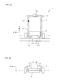
- FIG. 2A is a front view of the hand-propelled vehicle
- FIG. 2B is a top view of the hand-propelled vehicle.
- FIG. 3 is a block diagram that illustrates a configuration of the hand-propelled vehicle.
- FIG. 4 is a side view of the hand-propelled vehicle in a case where a support unit extends forward of a main wheel with respect to a direction of travel.
- FIGS. 5A and 5B include illustrations of a configuration of an inclination sensor.
- FIG. 6 is a control configuration diagram that illustrates a configuration of a control unit.
- FIGS. 7A-7C include illustrations of a relationship between an inclination angle of a road surface and a target inclination angle.
- FIG. 8 illustrates an inclination angle of a main body with respect to a vertical axis.
- FIG. 9 is a control configuration diagram that illustrates a configuration of the control unit.
- FIG. 10 is a control configuration diagram that illustrates a configuration of the control unit.
- FIG. 11 illustrates a relationship between a dead zone and the target inclination angle.
- FIG. 12 is a flowchart that illustrates operations of the control unit.
- FIGS. 13A-13C include illustrations of a relationship between the inclination angle of the road surface and the target inclination angle.
- FIGS. 14A and 14B include illustrations of a relationship between the dead zone and the target inclination angle according to a first variation and a second variation.
- FIG. 1 is a left side view of a hand-propelled vehicle 1 according to a first embodiment of the present disclosure
- FIG. 2A is a front view
- FIG. 2B is a plan view
- FIG. 3 is a block diagram that illustrates a hardware configuration of the hand-propelled vehicle 1 .
- the hand-propelled vehicle 1 includes a main body 10 having a shape that is long in a vertical direction (Z direction in the drawings) and short in a depth direction (Y direction in the drawings) and side-to-side direction (X direction in the drawings).
- a pair of main wheels 11 are mounted on ends in the side-to-side direction in a lower portion of the main body 10 in the downward vertical direction.
- This embodiment illustrates an example in which the number of main wheels 11 is two.
- the number of main wheels 11 may be one or three or more.
- the main body 10 has a shape of two bars coupled to the main wheels 11 , the two bars are connected together with a cylindrical grip unit 15 disposed therebetween in an upper portion, and the main body 10 is rotatable in a pitch direction about shafts of the main wheels 11 .
- the main body 10 may not have the shape of two bars in this example.
- the main body 10 may be a single bar member or may be a thin board member.
- a box 30 incorporating a substrate for control, a cell battery, and the like is disposed in the vicinity of the lower portion of the main body 10 . In actuality, a cover is attached to the main body 10 , and the internal substrate and the like are not seen in external appearance.
- the grip unit 15 has a cylindrical shape that is long in the side-to-side direction, is bent toward an opposite direction to the direction of travel (backward) in the vicinity of the left and right ends, and extends backward. This enables a location where a user grips the grip unit 15 to be shifted backward and can lead to a widen space around the feet of the user.
- Each of the rotating shafts of the main wheels 11 is coupled to a support unit 112 having a thin board shape extending backward.
- the support unit 112 is connected to the rotating shaft of the main wheel 11 and being rotatable in the pitch direction such that it extends in parallel to the road surface.
- the support unit 112 may not be parallel to the road surface.
- the support unit 112 may be connected to the rotating shaft of the main wheel 11 and being rotatable such that the angle to the road surface is always maintained at a predetermined angle.
- the support unit 112 is coupled to an auxiliary wheel 113 on a lower surface in a direction opposite the side where the support unit 112 is coupled to the rotating shaft of the main wheel 11 . Both the main wheel 11 and the auxiliary wheel 113 are in contact with the road surface. As illustrated in the side view in FIG. 4 , a form may be used in which the support unit 112 extends forward of the main wheel 11 with respect to the direction of travel. In this form, in which the support unit 112 extends forward of the main wheel 11 , the space around the feet of the user can be large.
- the main wheel 11 which has a larger inside diameter, is arranged forward with respect to the direction of travel, and thus the hand-propelled vehicle 1 can get over a step easily.
- FIGS. 1, 2A, 2B, and 4 illustrate a state in which the auxiliary wheels 113 are in contact with the road surface. Even in a state where only the main wheels 11 are in contact with the road surface, the hand-propelled vehicle 1 can stand on its own by inverted pendulum control.
- a motor may be mounted on a portion where the rotating shaft of the main wheel 11 and the support unit 112 are connected, a crossing angle being the angle between the rotating shaft of the main wheel 11 and the support unit 112 may be actively controlled by driving the motor.
- the two support units 112 and two auxiliary wheels 113 , one support unit 112 and auxiliary wheel 113 are coupled to the rotating shaft of the left auxiliary wheel 113 and the others are coupled to that of the right main wheel 11 .
- a form may be used in which one or three or more support units 112 and auxiliary wheels 113 are disposed. By coupling them to the rotating shafts of the left and right main wheels 11 , as illustrated in FIGS. 2A and 2B , the space around the feet of the user can be large.
- a user interface (I/F) 28 such as a power switch, is disposed on the grip unit 15 .
- the user can push the hand-propelled vehicle 1 in the direction of travel by gripping the grip unit 15 .
- the user can also push the hand-propelled vehicle 1 in the direction of travel while placing their forearm or the like on the grip unit 15 by friction produced between the grip unit 15 and their forearm or the like when pressing the forearm or the like against the grip unit 15 from above without necessarily gripping the grip unit 15 .
- the hand-propelled vehicle 1 includes an inclination sensor 20 , a control unit 21 , a read-only memory (ROM) 22 , a random-access memory (RAM) 23 , a gyro sensor 24 , a drive unit 25 , a support-unit rotary encoder 27 , and the user I/F 28 .
- ROM read-only memory
- RAM random-access memory
- the control unit 21 is a function unit that controls the hand-propelled vehicle 1 in a collective manner and achieves various operations by reading a program stored in the ROM 22 and developing the program in the RAM 23 .
- the inclination sensor 20 corresponds to a road-surface inclination angle detecting unit in the present disclosure, is mounted on the support unit, which is maintained in parallel to or at a constant angle to the road surface, detects the inclination angle of the road surface, and outputs it to the control unit 21 .
- the inclination sensor 20 is formed by processing a thin plate-like silicon wafer, as illustrated in FIG. 5A , and includes a spring 201 , a movable portion 202 , and a comb electrode portion 203 . As illustrated in FIG.
- the support-unit rotary encoder 27 corresponds to a crossing-angle detecting unit in the present disclosure, detects the crossing angle, which is the angle between the main body 10 and the support unit 112 , and outputs the result of detection to the control unit 21 .
- the crossing angle may be detected by a potentiometer, not only the rotary encoder.
- the gyro sensor 24 corresponds to an inclination angular velocity detecting unit in the present disclosure, detects the inclination angular velocity of the main body 10 in the pitch direction, and outputs it to the control unit 21 .
- the hand-propelled vehicle 1 may further include an acceleration sensor that detects an acceleration of the main body 10 in each of directions, a rotary encoder that detects a rotation angle of the main wheel 11 , a rotary encoder that detects a rotation angle of the auxiliary wheel 113 , and the like.
- FIG. 6 is a control configuration diagram of the control unit 21 .
- the control unit 21 includes a target inclination angle determining unit 211 , a target inclination angular velocity calculating unit 212 , a torque instruction generating unit 213 , an incline estimating unit 214 , and a main-body inclination angle calculating unit 215 .
- the target inclination angular velocity calculating unit 212 receives a difference value between the first angle and the inclination angle of the main body 10 with respect to the vertical axis at present and calculate an inclination angular velocity of the main body 10 at which the difference value is zero.
- the inclination angle of the main body 10 with respect to the vertical axis at present is calculated by the main-body inclination angle calculating unit 215 .
- the main-body inclination angle calculating unit 215 calculates the inclination angle of the main body 10 with respect to the vertical axis by using the crossing angle between the main body 10 and the support unit 112 input from the support-unit rotary encoder 27 and the inclination angle of the support unit 112 with respect to the vertical axis input from the inclination sensor 20 .
- the support unit 112 is connected to the shaft of the main wheel 11 such that it is parallel to a horizontal road surface. Accordingly, as illustrated in FIG.
- the main-body inclination angle calculating unit 215 calculates the inclination angle of the main body 10 with respect to the normal to the road surface at present such that in a case where the crossing angle is 90 degrees, the inclination angle of the main body 10 with respect to the normal to the road surface is determined to be 0 degree, such that in a case where the crossing angle increases, the main body 10 is determined to be inclined forward with respect to the direction of travel, and such that in a case where the crossing angle decreases, the main body 10 is determined to be inclined backward with respect to the direction of travel.
- crossing angle ⁇ 90° is calculated as the inclination angle with respect to the normal to the road surface such that in a case where the main body 10 is inclined forward with respect to the direction of travel, the inclination angle with respect to the normal to the road surface is a positive value and such that in a case where the main body 10 is inclined backward with respect to the direction of travel, it is a negative value.
- the support unit 112 and the road surface may not be parallel to each other. It is merely necessary that the support unit 112 is connected to the shaft of the main wheel 11 such that the support unit 112 and the road surface form a predetermined angle (known angle). In this case, the inclination angle of the main body 10 with respect to the vertical axis can be calculated by subtracting the predetermined angle from the crossing angle or adding the predetermined angle to the crossing angle.
- a method of integrating values output from the gyro sensor 24 may also be used in obtaining the inclination angle of the main body 10 with respect to the vertical axis.
- the inclination angle can be obtained from the inclination sensor 20 mounted on the main body 10 .
- the torque instruction generating unit 213 receives a difference value between the target inclination angular velocity calculated by the target inclination angular velocity calculating unit 212 and the inclination angular velocity of the main body 10 at present input from the gyro sensor 24 and calculates a torque to be applied such that the difference value is zero.
- the inclination angular velocity of the main body 10 can also be obtained by differentiating the inclination angle of the main body 10 estimated from the crossing angle.
- a control signal based on the torque to be applied calculated in this way is input to the drive unit 25 .
- the drive unit 25 is a function unit that drives the motor for driving the shaft mounted on the main wheel 11 and provides the main wheel 11 with power.
- the drive unit 25 drives the motor for the main wheel 11 on the basis of the input control signal and rotates the main wheel 11 .
- the hand-propelled vehicle 1 performs inverted pendulum control such that the position of the main body 10 is maintained constant. If the user pushes the hand-propelled vehicle 1 forward with respect to the direction of travel, because the inclination angle of the main body 10 is inclined forward with respect to the target inclination angle, a torque for driving the main wheel 11 in the forward direction is exerted in order to maintain the inclination angle of the main body 10 at the target inclination angle. This causes the hand-propelled vehicle 1 to move so as to follow movement of the user.
- the incline estimating unit 214 receives a value in the inclination sensor 20 and calculates the inclination angle of the road surface. As illustrated in FIGS. 7A, 7B, and 7C , because the support unit 112 is connected to the shaft of the main wheel 11 , the support unit 112 is always maintained in parallel to or at a predetermined angle to the road surface for any inclination angle of the main body 10 .
- the incline estimating unit 214 regards an inclination angle ⁇ 3 being the value in the inclination sensor 20 as being the same as the inclination angle ⁇ 2 of the road surface (or in a case where the support unit 112 is inclined a predetermined angle to the road surface, an angle from ⁇ 3 to the predetermined angle is subtracted from or added to the crossing angle) and outputs the estimated inclination angle ⁇ 2 of the road surface to the target inclination angle determining unit 211 .
- Approaches to adjusting an assisting force are not limited to changing the target inclination angle and may include adding an offset torque, as illustrated in FIG. 9 , for example.
- the incline estimating unit 214 calculates an offset torque for compensating for a gravitational torque generated depending on the inclination angle of the road surface in accordance with the inclination angle of the road surface estimated on the basis of the value in the inclination sensor 20 , by using a gravitational torque calculating unit 214 A.
- the offset torque is added to the torque calculated by the torque instruction generating unit 213 , and the torque is applied to the drive unit 25 .
- the offset torque may be applied.
- the hand-propelled vehicle according to the second embodiment differs from that according to the first embodiment in that the incline estimating unit 214 further determines whether a value input from the inclination sensor 20 is within a predetermined range (dead zone).
- a predetermined range dead zone
- an electrostatic capacity in the comb electrode portion is also changed in response to an acceleration in the direction of travel (Y direction). This may lead to incorrectly detecting an increase or decrease in speed as a change in the inclination angle of the road surface.
- the assisting force may be adjusted even when the inclination angle of the road surface is not changed in reality, and behavior of adjustment of the assisting force may be unstable.
- the hand-propelled vehicle aims to stabilize the behavior of adjustment of the assisting force in a case where the assisting force is adjusted in accordance with the inclination angle, and it determines whether a value input from the inclination sensor 20 is within a predetermined range (dead zone).
- the incline estimating unit 214 determines that the value in the inclination sensor 20 exceeds the dead zone, it informs the target inclination angle determining unit 211 of the value in the inclination sensor 20 and that it exceeds the dead zone.
- the target inclination angle determining unit 211 receives the information that the dead zone is exceeded, it sets the target inclination angle ⁇ 1 again.
- the target inclination angle determining unit 211 may set the target inclination angle again instantly at the point when the dead zone is exceeded, even for a moment, or may set the target inclination angle again after a predetermined elapsed time during which the dead zone is exceeded.
- control unit 21 may determine that the hand-propelled vehicle may be running on a rough road, an operator may have stumble, or the like and thus may perform control for stopping the hand-propelled vehicle 1 .
- FIG. 11 illustrates a relationship between the dead zone and the target inclination angle.
- the horizontal axis in the graph illustrated in FIG. 11 indicates a value in the inclination sensor 20
- the vertical axis indicates a target inclination angle.
- the hand-propelled vehicle 1 may include a rotary encoder that detects the rotation angle of the main wheel 11 or a rotary encoder that detect the rotation angle of the auxiliary wheel 113 .
- a rotary encoder senses that an absolute value of an acceleration of the hand-propelled vehicle 1 (main body 10 ) in the pitch direction is at or above a set value
- a threshold value range in the dead zone may be extended.
- the threshold value range in the dead zone may be narrowed.
- the threshold value range in the dead zone may be set such that it is proportional to the magnitude of the acceleration of the hand-propelled vehicle 1 (main body 10 ) in the pitch direction.
- the inclination angle of the road surface can be prevented from being incorrectly sensed.
- an inclination angle near a real inclination angle of the road surface can be detected without necessarily setting an unnecessary large dead zone.
- FIG. 12 is a flowchart that illustrates operations of the control unit 21 .
- the incline estimating unit 214 receives a value in the inclination sensor 20 (s 11 ) and determines whether the value in the inclination sensor 20 is within a predetermined range (dead zone) (s 12 ). In a case where the incline estimating unit determines that the value in the inclination sensor 20 exceeds the dead zone (Yes at s 12 ), the target inclination angle determining unit 211 sets the target inclination angle ⁇ 1 again (s 13 ).
- a real inclination angle of the road surface is a value near the border of the dead zone (for example, 5° or ⁇ 5°) or even when an increase or decrease in speed during acceleration or deceleration is incorrectly detected as a change in the inclination angle of the road surface of the inclination sensor 20 , adjustment of the assisting force is not frequently repeated, and behavior of adjustment of the assisting force can be stabilized.
- FIG. 14A illustrates a relationship between the dead zone and the target inclination angle in a first variation.
- the value in the inclination sensor 20 in a case where after the value in the inclination sensor 20 decreases and the assisting force is strongly adjusted, the value in the inclination sensor 20 further decreases or in a case where after the value in the inclination sensor 20 increases and the assisting force is weakly adjusted (or an assisting force in the opposite direction is set), the value in the inclination sensor 20 further increases, a new target inclination angle and dead zone are set again.
- the incline estimating unit 214 sets a new dead zone between ⁇ 8° and 0° with reference to the value ⁇ 5° in the inclination sensor 20 at the point in time when the dead zone is exceeded.
- the incline estimating unit 214 sets a new dead zone with reference to the value ⁇ 8° in the inclination sensor 20 at the point in time when the dead zone is exceeded.
- the new dead zone is ⁇ to ⁇ 5°.
- the target inclination angle ⁇ 1 is set again at the second angle and a new dead zone of ⁇ 8° to 0° is set again.
- the incline estimating unit 214 sets a new dead zone between 0° and 8° with reference to the value 5° in the inclination sensor 20 at the point in time when the dead zone is exceeded.
- the incline estimating unit 214 sets a new dead zone with reference to the value 8° in the inclination sensor 20 at the point in time when the dead zone is exceeded.
- the new dead zone is 5° to ⁇ .
- the target inclination angle ⁇ 1 is set again at the third angle and a new dead zone of 0° to 8° is set again.
- the control unit 21 can achieve appropriate adjustment without necessarily having to set a dead zone having the same width (for example, ⁇ 5°) with reference to a value that exceeds the dead zone.
- FIG. 14B illustrates a relationship between the dead zone and the target inclination angle according to a second variation.
- the incline estimating unit 214 sets a new dead zone at ⁇ to ⁇ 3°. This causes the target inclination angle ⁇ 1 to be set again at the fourth angle in a case where the value in the inclination sensor 20 falls below ⁇ 8° and be fixed at the fourth angle until it exceeds ⁇ 3°, and a strong assisting force is maintained.
- the target inclination angle ⁇ 1 is set again at the second angle and a new dead zone of ⁇ 8° to 0° is set again.
- the incline estimating unit 214 sets a new dead zone of 3° to ⁇ .
- the target inclination angle ⁇ 1 is set again at the fifth angle and is fixed at the fifth angle until it falls below 3°, and a strong braking effect is maintained.
- the target inclination angle ⁇ 1 is set again at the third angle and a new dead zone of 0° to 8° is set again.
- the borders of the dead zones are not necessarily the same value, and a form may also be used in which the value in the inclination sensor 20 to return to an original target inclination angle is set at a smaller value or larger value.
- the used form of the hand-propelled vehicle in the present disclosure is not limited to the examples illustrated in the present embodiments.
- a seat or the like may be provided on an upper portion of the box 30 , and the hand-propelled vehicle 1 may also be used as an electric baby transport.
- the hand-propelled vehicle 1 may also be used as an electric hand truck including a flat portion where goods can be placed.
Landscapes
- Health & Medical Sciences (AREA)
- Epidemiology (AREA)
- Pain & Pain Management (AREA)
- Physical Education & Sports Medicine (AREA)
- Rehabilitation Therapy (AREA)
- Life Sciences & Earth Sciences (AREA)
- Animal Behavior & Ethology (AREA)
- General Health & Medical Sciences (AREA)
- Public Health (AREA)
- Veterinary Medicine (AREA)
- Motorcycle And Bicycle Frame (AREA)
- Rehabilitation Tools (AREA)
Applications Claiming Priority (5)
| Application Number | Priority Date | Filing Date | Title |
|---|---|---|---|
| JP2013-266657 | 2013-12-25 | ||
| JP2013266657 | 2013-12-25 | ||
| JP2014-051062 | 2014-03-14 | ||
| JP2014051062 | 2014-03-14 | ||
| PCT/JP2014/083652 WO2015098722A1 (ja) | 2013-12-25 | 2014-12-19 | 手押し車 |
Related Parent Applications (1)
| Application Number | Title | Priority Date | Filing Date |
|---|---|---|---|
| PCT/JP2014/083652 Continuation WO2015098722A1 (ja) | 2013-12-25 | 2014-12-19 | 手押し車 |
Publications (2)
| Publication Number | Publication Date |
|---|---|
| US20160296411A1 US20160296411A1 (en) | 2016-10-13 |
| US10052253B2 true US10052253B2 (en) | 2018-08-21 |
Family
ID=53478580
Family Applications (1)
| Application Number | Title | Priority Date | Filing Date |
|---|---|---|---|
| US15/185,306 Expired - Fee Related US10052253B2 (en) | 2013-12-25 | 2016-06-17 | Hand-propelled vehicle |
Country Status (4)
| Country | Link |
|---|---|
| US (1) | US10052253B2 (ja) |
| JP (1) | JP5979322B2 (ja) |
| DE (1) | DE112014005989B4 (ja) |
| WO (1) | WO2015098722A1 (ja) |
Cited By (2)
| Publication number | Priority date | Publication date | Assignee | Title |
|---|---|---|---|---|
| US20210155278A1 (en) * | 2019-11-22 | 2021-05-27 | Suzuki Motor Corporation | Walking aid vehicle |
| US20220054346A1 (en) * | 2020-08-21 | 2022-02-24 | James L. King | Powered Walking Assistance Device With Cane Portion Used as Joystick Controller |
Families Citing this family (2)
| Publication number | Priority date | Publication date | Assignee | Title |
|---|---|---|---|---|
| JP6917579B2 (ja) * | 2017-01-19 | 2021-08-11 | パナソニックIpマネジメント株式会社 | 歩行転倒防止装置、制御装置、制御方法、並びに、プログラム |
| CN113998037B (zh) * | 2021-10-14 | 2023-07-25 | 株式会社Iat | 一种自行车的自动减速方法、装置及系统 |
Citations (15)
| Publication number | Priority date | Publication date | Assignee | Title |
|---|---|---|---|---|
| US6062600A (en) * | 1996-07-17 | 2000-05-16 | Deka Products Limited Partnership | Anti-tipping mechanism |
| US6571892B2 (en) * | 1999-03-15 | 2003-06-03 | Deka Research And Development Corporation | Control system and method |
| US7174976B2 (en) * | 2002-07-12 | 2007-02-13 | Deka Products Limited Partnership | Dynamically stable transporter controlled by lean |
| US7407187B2 (en) * | 2003-01-17 | 2008-08-05 | Toyota Jidosha Kabushiki Kaisha | Two-wheeled vehicle and chassis braking system |
| US20090138232A1 (en) * | 2006-10-05 | 2009-05-28 | Toshio Fuwa | Moving body with tilt angle estimating mechanism |
| US7783392B2 (en) * | 2005-10-13 | 2010-08-24 | Toyota Jidosha Kabushiki Kaisha | Traveling apparatus and method of controlling the same |
| US20120029696A1 (en) * | 2010-07-30 | 2012-02-02 | Toyota Motor Engineering & Manufacturing North America, Inc. | Robotic cane devices |
| WO2012114597A1 (ja) | 2011-02-23 | 2012-08-30 | 株式会社村田製作所 | 歩行補助車 |
| DE102011084236A1 (de) | 2011-10-10 | 2013-04-11 | Technische Universität München | Gehhilfe und Verfahren zur Steuerung einer Gehhilfe |
| US8423274B2 (en) * | 2007-03-27 | 2013-04-16 | Equos Research Co., Ltd. | Vehicle |
| JP2013188304A (ja) | 2012-03-13 | 2013-09-26 | Azbil Corp | 歩行支援機 |
| US20130274973A1 (en) * | 2006-03-06 | 2013-10-17 | Steven Kamara | Stair climbing wheeled vehicle, and system and method of making and using same |
| US8958976B2 (en) * | 2009-05-28 | 2015-02-17 | Toyota Jidosha Kabushiki Kaisha | Traveling apparatus, control method therefor, and control program |
| US9474678B2 (en) * | 2013-09-17 | 2016-10-25 | Murata Manufacturing Co., Ltd. | Pushcart |
| US9522611B2 (en) * | 2012-09-18 | 2016-12-20 | Murata Manufacturing Co., Ltd. | Inverted pendulum vehicle |
Family Cites Families (2)
| Publication number | Priority date | Publication date | Assignee | Title |
|---|---|---|---|---|
| JP2005193864A (ja) * | 2004-01-09 | 2005-07-21 | Yaskawa Electric Corp | キャリーバッグ |
| JP5045598B2 (ja) * | 2008-07-31 | 2012-10-10 | トヨタ自動車株式会社 | 搬送車及び連結機構 |
-
2014
- 2014-12-19 DE DE112014005989.7T patent/DE112014005989B4/de not_active Expired - Fee Related
- 2014-12-19 JP JP2015554817A patent/JP5979322B2/ja not_active Expired - Fee Related
- 2014-12-19 WO PCT/JP2014/083652 patent/WO2015098722A1/ja active Application Filing
-
2016
- 2016-06-17 US US15/185,306 patent/US10052253B2/en not_active Expired - Fee Related
Patent Citations (17)
| Publication number | Priority date | Publication date | Assignee | Title |
|---|---|---|---|---|
| US6062600A (en) * | 1996-07-17 | 2000-05-16 | Deka Products Limited Partnership | Anti-tipping mechanism |
| US6571892B2 (en) * | 1999-03-15 | 2003-06-03 | Deka Research And Development Corporation | Control system and method |
| US7174976B2 (en) * | 2002-07-12 | 2007-02-13 | Deka Products Limited Partnership | Dynamically stable transporter controlled by lean |
| US7407187B2 (en) * | 2003-01-17 | 2008-08-05 | Toyota Jidosha Kabushiki Kaisha | Two-wheeled vehicle and chassis braking system |
| US7783392B2 (en) * | 2005-10-13 | 2010-08-24 | Toyota Jidosha Kabushiki Kaisha | Traveling apparatus and method of controlling the same |
| US20130274973A1 (en) * | 2006-03-06 | 2013-10-17 | Steven Kamara | Stair climbing wheeled vehicle, and system and method of making and using same |
| US20090138232A1 (en) * | 2006-10-05 | 2009-05-28 | Toshio Fuwa | Moving body with tilt angle estimating mechanism |
| US8423274B2 (en) * | 2007-03-27 | 2013-04-16 | Equos Research Co., Ltd. | Vehicle |
| US8958976B2 (en) * | 2009-05-28 | 2015-02-17 | Toyota Jidosha Kabushiki Kaisha | Traveling apparatus, control method therefor, and control program |
| US20120029696A1 (en) * | 2010-07-30 | 2012-02-02 | Toyota Motor Engineering & Manufacturing North America, Inc. | Robotic cane devices |
| US20130306120A1 (en) * | 2011-02-23 | 2013-11-21 | Murata Manufacturing Co., Ltd. | Walking assist apparatus |
| EP2666453A1 (en) | 2011-02-23 | 2013-11-27 | Murata Manufacturing Co., Ltd. | Walking frame |
| WO2012114597A1 (ja) | 2011-02-23 | 2012-08-30 | 株式会社村田製作所 | 歩行補助車 |
| DE102011084236A1 (de) | 2011-10-10 | 2013-04-11 | Technische Universität München | Gehhilfe und Verfahren zur Steuerung einer Gehhilfe |
| JP2013188304A (ja) | 2012-03-13 | 2013-09-26 | Azbil Corp | 歩行支援機 |
| US9522611B2 (en) * | 2012-09-18 | 2016-12-20 | Murata Manufacturing Co., Ltd. | Inverted pendulum vehicle |
| US9474678B2 (en) * | 2013-09-17 | 2016-10-25 | Murata Manufacturing Co., Ltd. | Pushcart |
Non-Patent Citations (2)
| Title |
|---|
| International Search report for PCT/JP2014/083652 dated Apr. 7, 2015. |
| Written Opinion for PCT/JP2014/083652 dated Apr. 7, 2015. |
Cited By (3)
| Publication number | Priority date | Publication date | Assignee | Title |
|---|---|---|---|---|
| US20210155278A1 (en) * | 2019-11-22 | 2021-05-27 | Suzuki Motor Corporation | Walking aid vehicle |
| US11702122B2 (en) * | 2019-11-22 | 2023-07-18 | Suzuki Motor Corporation | Walking aid vehicle |
| US20220054346A1 (en) * | 2020-08-21 | 2022-02-24 | James L. King | Powered Walking Assistance Device With Cane Portion Used as Joystick Controller |
Also Published As
| Publication number | Publication date |
|---|---|
| WO2015098722A1 (ja) | 2015-07-02 |
| JPWO2015098722A1 (ja) | 2017-03-23 |
| JP5979322B2 (ja) | 2016-08-24 |
| DE112014005989T5 (de) | 2016-09-08 |
| DE112014005989B4 (de) | 2017-07-06 |
| US20160296411A1 (en) | 2016-10-13 |
Similar Documents
| Publication | Publication Date | Title |
|---|---|---|
| US10052253B2 (en) | Hand-propelled vehicle | |
| US9604697B2 (en) | Mobility vehicle and power-assisting system | |
| US10183687B2 (en) | Pushcart | |
| US8447506B2 (en) | Traveling device and its control method | |
| US8862301B2 (en) | Inverted pendulum type vehicle | |
| US9845101B2 (en) | Pushcart | |
| US9317039B2 (en) | Inverted pendulum type vehicle | |
| US9474678B2 (en) | Pushcart | |
| JP4625859B2 (ja) | 倒立振子型移動機構 | |
| EP2783959A1 (en) | Inverted pendulum type vehicle | |
| US20150183463A1 (en) | Pushcart | |
| JP6252683B2 (ja) | 手押し車 | |
| US9724261B2 (en) | Handcart | |
| JP5800110B2 (ja) | 手押し車 | |
| JP5979321B2 (ja) | 手押し車 | |
| JP5958546B2 (ja) | 手押し車 | |
| JP5704283B2 (ja) | 手押し車 | |
| JP5935965B1 (ja) | 手押し車 | |
| Takita et al. | Implementation of SSM to Lateral Guided Steering Vehicle With Body Fixed High-Speed Camera |
Legal Events
| Date | Code | Title | Description |
|---|---|---|---|
| AS | Assignment |
Owner name: MURATA MANUFACTURING CO., LTD., JAPAN Free format text: ASSIGNMENT OF ASSIGNORS INTEREST;ASSIGNORS:SHIRATO, KENICHI;TSUJI, SHIGERU;KUBO, MASAYUKI;AND OTHERS;REEL/FRAME:038942/0122 Effective date: 20160516 |
|
| STCF | Information on status: patent grant |
Free format text: PATENTED CASE |
|
| FEPP | Fee payment procedure |
Free format text: MAINTENANCE FEE REMINDER MAILED (ORIGINAL EVENT CODE: REM.); ENTITY STATUS OF PATENT OWNER: LARGE ENTITY |
|
| LAPS | Lapse for failure to pay maintenance fees |
Free format text: PATENT EXPIRED FOR FAILURE TO PAY MAINTENANCE FEES (ORIGINAL EVENT CODE: EXP.); ENTITY STATUS OF PATENT OWNER: LARGE ENTITY |
|
| STCH | Information on status: patent discontinuation |
Free format text: PATENT EXPIRED DUE TO NONPAYMENT OF MAINTENANCE FEES UNDER 37 CFR 1.362 |
|
| FP | Lapsed due to failure to pay maintenance fee |
Effective date: 20220821 |