US10046753B2 - Vehicle hybrid system - Google Patents
Vehicle hybrid system Download PDFInfo
- Publication number
- US10046753B2 US10046753B2 US15/032,657 US201515032657A US10046753B2 US 10046753 B2 US10046753 B2 US 10046753B2 US 201515032657 A US201515032657 A US 201515032657A US 10046753 B2 US10046753 B2 US 10046753B2
- Authority
- US
- United States
- Prior art keywords
- motor generator
- engine
- transmission
- vehicle
- power connecting
- Prior art date
- Legal status (The legal status is an assumption and is not a legal conclusion. Google has not performed a legal analysis and makes no representation as to the accuracy of the status listed.)
- Active, expires
Links
Images


Classifications
-
- B—PERFORMING OPERATIONS; TRANSPORTING
- B60—VEHICLES IN GENERAL
- B60W—CONJOINT CONTROL OF VEHICLE SUB-UNITS OF DIFFERENT TYPE OR DIFFERENT FUNCTION; CONTROL SYSTEMS SPECIALLY ADAPTED FOR HYBRID VEHICLES; ROAD VEHICLE DRIVE CONTROL SYSTEMS FOR PURPOSES NOT RELATED TO THE CONTROL OF A PARTICULAR SUB-UNIT
- B60W20/00—Control systems specially adapted for hybrid vehicles
- B60W20/10—Controlling the power contribution of each of the prime movers to meet required power demand
-
- B—PERFORMING OPERATIONS; TRANSPORTING
- B60—VEHICLES IN GENERAL
- B60K—ARRANGEMENT OR MOUNTING OF PROPULSION UNITS OR OF TRANSMISSIONS IN VEHICLES; ARRANGEMENT OR MOUNTING OF PLURAL DIVERSE PRIME-MOVERS IN VEHICLES; AUXILIARY DRIVES FOR VEHICLES; INSTRUMENTATION OR DASHBOARDS FOR VEHICLES; ARRANGEMENTS IN CONNECTION WITH COOLING, AIR INTAKE, GAS EXHAUST OR FUEL SUPPLY OF PROPULSION UNITS IN VEHICLES
- B60K6/00—Arrangement or mounting of plural diverse prime-movers for mutual or common propulsion, e.g. hybrid propulsion systems comprising electric motors and internal combustion engines
- B60K6/20—Arrangement or mounting of plural diverse prime-movers for mutual or common propulsion, e.g. hybrid propulsion systems comprising electric motors and internal combustion engines the prime-movers consisting of electric motors and internal combustion engines, e.g. HEVs
- B60K6/22—Arrangement or mounting of plural diverse prime-movers for mutual or common propulsion, e.g. hybrid propulsion systems comprising electric motors and internal combustion engines the prime-movers consisting of electric motors and internal combustion engines, e.g. HEVs characterised by apparatus, components or means specially adapted for HEVs
- B60K6/26—Arrangement or mounting of plural diverse prime-movers for mutual or common propulsion, e.g. hybrid propulsion systems comprising electric motors and internal combustion engines the prime-movers consisting of electric motors and internal combustion engines, e.g. HEVs characterised by apparatus, components or means specially adapted for HEVs characterised by the motors or the generators
-
- B—PERFORMING OPERATIONS; TRANSPORTING
- B60—VEHICLES IN GENERAL
- B60K—ARRANGEMENT OR MOUNTING OF PROPULSION UNITS OR OF TRANSMISSIONS IN VEHICLES; ARRANGEMENT OR MOUNTING OF PLURAL DIVERSE PRIME-MOVERS IN VEHICLES; AUXILIARY DRIVES FOR VEHICLES; INSTRUMENTATION OR DASHBOARDS FOR VEHICLES; ARRANGEMENTS IN CONNECTION WITH COOLING, AIR INTAKE, GAS EXHAUST OR FUEL SUPPLY OF PROPULSION UNITS IN VEHICLES
- B60K6/00—Arrangement or mounting of plural diverse prime-movers for mutual or common propulsion, e.g. hybrid propulsion systems comprising electric motors and internal combustion engines
- B60K6/20—Arrangement or mounting of plural diverse prime-movers for mutual or common propulsion, e.g. hybrid propulsion systems comprising electric motors and internal combustion engines the prime-movers consisting of electric motors and internal combustion engines, e.g. HEVs
- B60K6/22—Arrangement or mounting of plural diverse prime-movers for mutual or common propulsion, e.g. hybrid propulsion systems comprising electric motors and internal combustion engines the prime-movers consisting of electric motors and internal combustion engines, e.g. HEVs characterised by apparatus, components or means specially adapted for HEVs
- B60K6/38—Arrangement or mounting of plural diverse prime-movers for mutual or common propulsion, e.g. hybrid propulsion systems comprising electric motors and internal combustion engines the prime-movers consisting of electric motors and internal combustion engines, e.g. HEVs characterised by apparatus, components or means specially adapted for HEVs characterised by the driveline clutches
- B60K6/383—One-way clutches or freewheel devices
-
- B—PERFORMING OPERATIONS; TRANSPORTING
- B60—VEHICLES IN GENERAL
- B60K—ARRANGEMENT OR MOUNTING OF PROPULSION UNITS OR OF TRANSMISSIONS IN VEHICLES; ARRANGEMENT OR MOUNTING OF PLURAL DIVERSE PRIME-MOVERS IN VEHICLES; AUXILIARY DRIVES FOR VEHICLES; INSTRUMENTATION OR DASHBOARDS FOR VEHICLES; ARRANGEMENTS IN CONNECTION WITH COOLING, AIR INTAKE, GAS EXHAUST OR FUEL SUPPLY OF PROPULSION UNITS IN VEHICLES
- B60K6/00—Arrangement or mounting of plural diverse prime-movers for mutual or common propulsion, e.g. hybrid propulsion systems comprising electric motors and internal combustion engines
- B60K6/20—Arrangement or mounting of plural diverse prime-movers for mutual or common propulsion, e.g. hybrid propulsion systems comprising electric motors and internal combustion engines the prime-movers consisting of electric motors and internal combustion engines, e.g. HEVs
- B60K6/22—Arrangement or mounting of plural diverse prime-movers for mutual or common propulsion, e.g. hybrid propulsion systems comprising electric motors and internal combustion engines the prime-movers consisting of electric motors and internal combustion engines, e.g. HEVs characterised by apparatus, components or means specially adapted for HEVs
- B60K6/38—Arrangement or mounting of plural diverse prime-movers for mutual or common propulsion, e.g. hybrid propulsion systems comprising electric motors and internal combustion engines the prime-movers consisting of electric motors and internal combustion engines, e.g. HEVs characterised by apparatus, components or means specially adapted for HEVs characterised by the driveline clutches
- B60K6/387—Actuated clutches, i.e. clutches engaged or disengaged by electric, hydraulic or mechanical actuating means
-
- B—PERFORMING OPERATIONS; TRANSPORTING
- B60—VEHICLES IN GENERAL
- B60K—ARRANGEMENT OR MOUNTING OF PROPULSION UNITS OR OF TRANSMISSIONS IN VEHICLES; ARRANGEMENT OR MOUNTING OF PLURAL DIVERSE PRIME-MOVERS IN VEHICLES; AUXILIARY DRIVES FOR VEHICLES; INSTRUMENTATION OR DASHBOARDS FOR VEHICLES; ARRANGEMENTS IN CONNECTION WITH COOLING, AIR INTAKE, GAS EXHAUST OR FUEL SUPPLY OF PROPULSION UNITS IN VEHICLES
- B60K6/00—Arrangement or mounting of plural diverse prime-movers for mutual or common propulsion, e.g. hybrid propulsion systems comprising electric motors and internal combustion engines
- B60K6/20—Arrangement or mounting of plural diverse prime-movers for mutual or common propulsion, e.g. hybrid propulsion systems comprising electric motors and internal combustion engines the prime-movers consisting of electric motors and internal combustion engines, e.g. HEVs
- B60K6/42—Arrangement or mounting of plural diverse prime-movers for mutual or common propulsion, e.g. hybrid propulsion systems comprising electric motors and internal combustion engines the prime-movers consisting of electric motors and internal combustion engines, e.g. HEVs characterised by the architecture of the hybrid electric vehicle
- B60K6/44—Series-parallel type
- B60K6/442—Series-parallel switching type
-
- B—PERFORMING OPERATIONS; TRANSPORTING
- B60—VEHICLES IN GENERAL
- B60K—ARRANGEMENT OR MOUNTING OF PROPULSION UNITS OR OF TRANSMISSIONS IN VEHICLES; ARRANGEMENT OR MOUNTING OF PLURAL DIVERSE PRIME-MOVERS IN VEHICLES; AUXILIARY DRIVES FOR VEHICLES; INSTRUMENTATION OR DASHBOARDS FOR VEHICLES; ARRANGEMENTS IN CONNECTION WITH COOLING, AIR INTAKE, GAS EXHAUST OR FUEL SUPPLY OF PROPULSION UNITS IN VEHICLES
- B60K6/00—Arrangement or mounting of plural diverse prime-movers for mutual or common propulsion, e.g. hybrid propulsion systems comprising electric motors and internal combustion engines
- B60K6/20—Arrangement or mounting of plural diverse prime-movers for mutual or common propulsion, e.g. hybrid propulsion systems comprising electric motors and internal combustion engines the prime-movers consisting of electric motors and internal combustion engines, e.g. HEVs
- B60K6/42—Arrangement or mounting of plural diverse prime-movers for mutual or common propulsion, e.g. hybrid propulsion systems comprising electric motors and internal combustion engines the prime-movers consisting of electric motors and internal combustion engines, e.g. HEVs characterised by the architecture of the hybrid electric vehicle
- B60K6/48—Parallel type
-
- B—PERFORMING OPERATIONS; TRANSPORTING
- B60—VEHICLES IN GENERAL
- B60K—ARRANGEMENT OR MOUNTING OF PROPULSION UNITS OR OF TRANSMISSIONS IN VEHICLES; ARRANGEMENT OR MOUNTING OF PLURAL DIVERSE PRIME-MOVERS IN VEHICLES; AUXILIARY DRIVES FOR VEHICLES; INSTRUMENTATION OR DASHBOARDS FOR VEHICLES; ARRANGEMENTS IN CONNECTION WITH COOLING, AIR INTAKE, GAS EXHAUST OR FUEL SUPPLY OF PROPULSION UNITS IN VEHICLES
- B60K6/00—Arrangement or mounting of plural diverse prime-movers for mutual or common propulsion, e.g. hybrid propulsion systems comprising electric motors and internal combustion engines
- B60K6/20—Arrangement or mounting of plural diverse prime-movers for mutual or common propulsion, e.g. hybrid propulsion systems comprising electric motors and internal combustion engines the prime-movers consisting of electric motors and internal combustion engines, e.g. HEVs
- B60K6/50—Architecture of the driveline characterised by arrangement or kind of transmission units
- B60K6/54—Transmission for changing ratio
- B60K6/547—Transmission for changing ratio the transmission being a stepped gearing
-
- B60L11/14—
-
- B—PERFORMING OPERATIONS; TRANSPORTING
- B60—VEHICLES IN GENERAL
- B60L—PROPULSION OF ELECTRICALLY-PROPELLED VEHICLES; SUPPLYING ELECTRIC POWER FOR AUXILIARY EQUIPMENT OF ELECTRICALLY-PROPELLED VEHICLES; ELECTRODYNAMIC BRAKE SYSTEMS FOR VEHICLES IN GENERAL; MAGNETIC SUSPENSION OR LEVITATION FOR VEHICLES; MONITORING OPERATING VARIABLES OF ELECTRICALLY-PROPELLED VEHICLES; ELECTRIC SAFETY DEVICES FOR ELECTRICALLY-PROPELLED VEHICLES
- B60L15/00—Methods, circuits, or devices for controlling the traction-motor speed of electrically-propelled vehicles
- B60L15/20—Methods, circuits, or devices for controlling the traction-motor speed of electrically-propelled vehicles for control of the vehicle or its driving motor to achieve a desired performance, e.g. speed, torque, programmed variation of speed
- B60L15/2009—Methods, circuits, or devices for controlling the traction-motor speed of electrically-propelled vehicles for control of the vehicle or its driving motor to achieve a desired performance, e.g. speed, torque, programmed variation of speed for braking
-
- B—PERFORMING OPERATIONS; TRANSPORTING
- B60—VEHICLES IN GENERAL
- B60L—PROPULSION OF ELECTRICALLY-PROPELLED VEHICLES; SUPPLYING ELECTRIC POWER FOR AUXILIARY EQUIPMENT OF ELECTRICALLY-PROPELLED VEHICLES; ELECTRODYNAMIC BRAKE SYSTEMS FOR VEHICLES IN GENERAL; MAGNETIC SUSPENSION OR LEVITATION FOR VEHICLES; MONITORING OPERATING VARIABLES OF ELECTRICALLY-PROPELLED VEHICLES; ELECTRIC SAFETY DEVICES FOR ELECTRICALLY-PROPELLED VEHICLES
- B60L15/00—Methods, circuits, or devices for controlling the traction-motor speed of electrically-propelled vehicles
- B60L15/20—Methods, circuits, or devices for controlling the traction-motor speed of electrically-propelled vehicles for control of the vehicle or its driving motor to achieve a desired performance, e.g. speed, torque, programmed variation of speed
- B60L15/2054—Methods, circuits, or devices for controlling the traction-motor speed of electrically-propelled vehicles for control of the vehicle or its driving motor to achieve a desired performance, e.g. speed, torque, programmed variation of speed by controlling transmissions or clutches
-
- B—PERFORMING OPERATIONS; TRANSPORTING
- B60—VEHICLES IN GENERAL
- B60L—PROPULSION OF ELECTRICALLY-PROPELLED VEHICLES; SUPPLYING ELECTRIC POWER FOR AUXILIARY EQUIPMENT OF ELECTRICALLY-PROPELLED VEHICLES; ELECTRODYNAMIC BRAKE SYSTEMS FOR VEHICLES IN GENERAL; MAGNETIC SUSPENSION OR LEVITATION FOR VEHICLES; MONITORING OPERATING VARIABLES OF ELECTRICALLY-PROPELLED VEHICLES; ELECTRIC SAFETY DEVICES FOR ELECTRICALLY-PROPELLED VEHICLES
- B60L50/00—Electric propulsion with power supplied within the vehicle
- B60L50/10—Electric propulsion with power supplied within the vehicle using propulsion power supplied by engine-driven generators, e.g. generators driven by combustion engines
- B60L50/16—Electric propulsion with power supplied within the vehicle using propulsion power supplied by engine-driven generators, e.g. generators driven by combustion engines with provision for separate direct mechanical propulsion
-
- B—PERFORMING OPERATIONS; TRANSPORTING
- B60—VEHICLES IN GENERAL
- B60L—PROPULSION OF ELECTRICALLY-PROPELLED VEHICLES; SUPPLYING ELECTRIC POWER FOR AUXILIARY EQUIPMENT OF ELECTRICALLY-PROPELLED VEHICLES; ELECTRODYNAMIC BRAKE SYSTEMS FOR VEHICLES IN GENERAL; MAGNETIC SUSPENSION OR LEVITATION FOR VEHICLES; MONITORING OPERATING VARIABLES OF ELECTRICALLY-PROPELLED VEHICLES; ELECTRIC SAFETY DEVICES FOR ELECTRICALLY-PROPELLED VEHICLES
- B60L7/00—Electrodynamic brake systems for vehicles in general
- B60L7/10—Dynamic electric regenerative braking
- B60L7/14—Dynamic electric regenerative braking for vehicles propelled by AC motors
-
- B—PERFORMING OPERATIONS; TRANSPORTING
- B60—VEHICLES IN GENERAL
- B60W—CONJOINT CONTROL OF VEHICLE SUB-UNITS OF DIFFERENT TYPE OR DIFFERENT FUNCTION; CONTROL SYSTEMS SPECIALLY ADAPTED FOR HYBRID VEHICLES; ROAD VEHICLE DRIVE CONTROL SYSTEMS FOR PURPOSES NOT RELATED TO THE CONTROL OF A PARTICULAR SUB-UNIT
- B60W10/00—Conjoint control of vehicle sub-units of different type or different function
- B60W10/02—Conjoint control of vehicle sub-units of different type or different function including control of driveline clutches
-
- B—PERFORMING OPERATIONS; TRANSPORTING
- B60—VEHICLES IN GENERAL
- B60W—CONJOINT CONTROL OF VEHICLE SUB-UNITS OF DIFFERENT TYPE OR DIFFERENT FUNCTION; CONTROL SYSTEMS SPECIALLY ADAPTED FOR HYBRID VEHICLES; ROAD VEHICLE DRIVE CONTROL SYSTEMS FOR PURPOSES NOT RELATED TO THE CONTROL OF A PARTICULAR SUB-UNIT
- B60W10/00—Conjoint control of vehicle sub-units of different type or different function
- B60W10/04—Conjoint control of vehicle sub-units of different type or different function including control of propulsion units
- B60W10/06—Conjoint control of vehicle sub-units of different type or different function including control of propulsion units including control of combustion engines
-
- B—PERFORMING OPERATIONS; TRANSPORTING
- B60—VEHICLES IN GENERAL
- B60W—CONJOINT CONTROL OF VEHICLE SUB-UNITS OF DIFFERENT TYPE OR DIFFERENT FUNCTION; CONTROL SYSTEMS SPECIALLY ADAPTED FOR HYBRID VEHICLES; ROAD VEHICLE DRIVE CONTROL SYSTEMS FOR PURPOSES NOT RELATED TO THE CONTROL OF A PARTICULAR SUB-UNIT
- B60W10/00—Conjoint control of vehicle sub-units of different type or different function
- B60W10/04—Conjoint control of vehicle sub-units of different type or different function including control of propulsion units
- B60W10/08—Conjoint control of vehicle sub-units of different type or different function including control of propulsion units including control of electric propulsion units, e.g. motors or generators
-
- B—PERFORMING OPERATIONS; TRANSPORTING
- B60—VEHICLES IN GENERAL
- B60W—CONJOINT CONTROL OF VEHICLE SUB-UNITS OF DIFFERENT TYPE OR DIFFERENT FUNCTION; CONTROL SYSTEMS SPECIALLY ADAPTED FOR HYBRID VEHICLES; ROAD VEHICLE DRIVE CONTROL SYSTEMS FOR PURPOSES NOT RELATED TO THE CONTROL OF A PARTICULAR SUB-UNIT
- B60W20/00—Control systems specially adapted for hybrid vehicles
- B60W20/40—Controlling the engagement or disengagement of prime movers, e.g. for transition between prime movers
-
- B—PERFORMING OPERATIONS; TRANSPORTING
- B60—VEHICLES IN GENERAL
- B60K—ARRANGEMENT OR MOUNTING OF PROPULSION UNITS OR OF TRANSMISSIONS IN VEHICLES; ARRANGEMENT OR MOUNTING OF PLURAL DIVERSE PRIME-MOVERS IN VEHICLES; AUXILIARY DRIVES FOR VEHICLES; INSTRUMENTATION OR DASHBOARDS FOR VEHICLES; ARRANGEMENTS IN CONNECTION WITH COOLING, AIR INTAKE, GAS EXHAUST OR FUEL SUPPLY OF PROPULSION UNITS IN VEHICLES
- B60K6/00—Arrangement or mounting of plural diverse prime-movers for mutual or common propulsion, e.g. hybrid propulsion systems comprising electric motors and internal combustion engines
- B60K6/20—Arrangement or mounting of plural diverse prime-movers for mutual or common propulsion, e.g. hybrid propulsion systems comprising electric motors and internal combustion engines the prime-movers consisting of electric motors and internal combustion engines, e.g. HEVs
- B60K6/22—Arrangement or mounting of plural diverse prime-movers for mutual or common propulsion, e.g. hybrid propulsion systems comprising electric motors and internal combustion engines the prime-movers consisting of electric motors and internal combustion engines, e.g. HEVs characterised by apparatus, components or means specially adapted for HEVs
- B60K6/26—Arrangement or mounting of plural diverse prime-movers for mutual or common propulsion, e.g. hybrid propulsion systems comprising electric motors and internal combustion engines the prime-movers consisting of electric motors and internal combustion engines, e.g. HEVs characterised by apparatus, components or means specially adapted for HEVs characterised by the motors or the generators
- B60K2006/268—Electric drive motor starts the engine, i.e. used as starter motor
-
- B—PERFORMING OPERATIONS; TRANSPORTING
- B60—VEHICLES IN GENERAL
- B60K—ARRANGEMENT OR MOUNTING OF PROPULSION UNITS OR OF TRANSMISSIONS IN VEHICLES; ARRANGEMENT OR MOUNTING OF PLURAL DIVERSE PRIME-MOVERS IN VEHICLES; AUXILIARY DRIVES FOR VEHICLES; INSTRUMENTATION OR DASHBOARDS FOR VEHICLES; ARRANGEMENTS IN CONNECTION WITH COOLING, AIR INTAKE, GAS EXHAUST OR FUEL SUPPLY OF PROPULSION UNITS IN VEHICLES
- B60K6/00—Arrangement or mounting of plural diverse prime-movers for mutual or common propulsion, e.g. hybrid propulsion systems comprising electric motors and internal combustion engines
- B60K6/20—Arrangement or mounting of plural diverse prime-movers for mutual or common propulsion, e.g. hybrid propulsion systems comprising electric motors and internal combustion engines the prime-movers consisting of electric motors and internal combustion engines, e.g. HEVs
- B60K6/42—Arrangement or mounting of plural diverse prime-movers for mutual or common propulsion, e.g. hybrid propulsion systems comprising electric motors and internal combustion engines the prime-movers consisting of electric motors and internal combustion engines, e.g. HEVs characterised by the architecture of the hybrid electric vehicle
- B60K6/48—Parallel type
- B60K2006/4808—Electric machine connected or connectable to gearbox output shaft
-
- B—PERFORMING OPERATIONS; TRANSPORTING
- B60—VEHICLES IN GENERAL
- B60K—ARRANGEMENT OR MOUNTING OF PROPULSION UNITS OR OF TRANSMISSIONS IN VEHICLES; ARRANGEMENT OR MOUNTING OF PLURAL DIVERSE PRIME-MOVERS IN VEHICLES; AUXILIARY DRIVES FOR VEHICLES; INSTRUMENTATION OR DASHBOARDS FOR VEHICLES; ARRANGEMENTS IN CONNECTION WITH COOLING, AIR INTAKE, GAS EXHAUST OR FUEL SUPPLY OF PROPULSION UNITS IN VEHICLES
- B60K6/00—Arrangement or mounting of plural diverse prime-movers for mutual or common propulsion, e.g. hybrid propulsion systems comprising electric motors and internal combustion engines
- B60K6/20—Arrangement or mounting of plural diverse prime-movers for mutual or common propulsion, e.g. hybrid propulsion systems comprising electric motors and internal combustion engines the prime-movers consisting of electric motors and internal combustion engines, e.g. HEVs
- B60K6/42—Arrangement or mounting of plural diverse prime-movers for mutual or common propulsion, e.g. hybrid propulsion systems comprising electric motors and internal combustion engines the prime-movers consisting of electric motors and internal combustion engines, e.g. HEVs characterised by the architecture of the hybrid electric vehicle
- B60K6/48—Parallel type
- B60K2006/4825—Electric machine connected or connectable to gearbox input shaft
-
- B—PERFORMING OPERATIONS; TRANSPORTING
- B60—VEHICLES IN GENERAL
- B60K—ARRANGEMENT OR MOUNTING OF PROPULSION UNITS OR OF TRANSMISSIONS IN VEHICLES; ARRANGEMENT OR MOUNTING OF PLURAL DIVERSE PRIME-MOVERS IN VEHICLES; AUXILIARY DRIVES FOR VEHICLES; INSTRUMENTATION OR DASHBOARDS FOR VEHICLES; ARRANGEMENTS IN CONNECTION WITH COOLING, AIR INTAKE, GAS EXHAUST OR FUEL SUPPLY OF PROPULSION UNITS IN VEHICLES
- B60K6/00—Arrangement or mounting of plural diverse prime-movers for mutual or common propulsion, e.g. hybrid propulsion systems comprising electric motors and internal combustion engines
- B60K6/20—Arrangement or mounting of plural diverse prime-movers for mutual or common propulsion, e.g. hybrid propulsion systems comprising electric motors and internal combustion engines the prime-movers consisting of electric motors and internal combustion engines, e.g. HEVs
- B60K6/42—Arrangement or mounting of plural diverse prime-movers for mutual or common propulsion, e.g. hybrid propulsion systems comprising electric motors and internal combustion engines the prime-movers consisting of electric motors and internal combustion engines, e.g. HEVs characterised by the architecture of the hybrid electric vehicle
- B60K6/48—Parallel type
- B60K2006/4833—Step up or reduction gearing driving generator, e.g. to operate generator in most efficient speed range
-
- B—PERFORMING OPERATIONS; TRANSPORTING
- B60—VEHICLES IN GENERAL
- B60L—PROPULSION OF ELECTRICALLY-PROPELLED VEHICLES; SUPPLYING ELECTRIC POWER FOR AUXILIARY EQUIPMENT OF ELECTRICALLY-PROPELLED VEHICLES; ELECTRODYNAMIC BRAKE SYSTEMS FOR VEHICLES IN GENERAL; MAGNETIC SUSPENSION OR LEVITATION FOR VEHICLES; MONITORING OPERATING VARIABLES OF ELECTRICALLY-PROPELLED VEHICLES; ELECTRIC SAFETY DEVICES FOR ELECTRICALLY-PROPELLED VEHICLES
- B60L2240/00—Control parameters of input or output; Target parameters
- B60L2240/10—Vehicle control parameters
- B60L2240/12—Speed
-
- B—PERFORMING OPERATIONS; TRANSPORTING
- B60—VEHICLES IN GENERAL
- B60L—PROPULSION OF ELECTRICALLY-PROPELLED VEHICLES; SUPPLYING ELECTRIC POWER FOR AUXILIARY EQUIPMENT OF ELECTRICALLY-PROPELLED VEHICLES; ELECTRODYNAMIC BRAKE SYSTEMS FOR VEHICLES IN GENERAL; MAGNETIC SUSPENSION OR LEVITATION FOR VEHICLES; MONITORING OPERATING VARIABLES OF ELECTRICALLY-PROPELLED VEHICLES; ELECTRIC SAFETY DEVICES FOR ELECTRICALLY-PROPELLED VEHICLES
- B60L2240/00—Control parameters of input or output; Target parameters
- B60L2240/40—Drive Train control parameters
- B60L2240/42—Drive Train control parameters related to electric machines
- B60L2240/421—Speed
-
- B—PERFORMING OPERATIONS; TRANSPORTING
- B60—VEHICLES IN GENERAL
- B60L—PROPULSION OF ELECTRICALLY-PROPELLED VEHICLES; SUPPLYING ELECTRIC POWER FOR AUXILIARY EQUIPMENT OF ELECTRICALLY-PROPELLED VEHICLES; ELECTRODYNAMIC BRAKE SYSTEMS FOR VEHICLES IN GENERAL; MAGNETIC SUSPENSION OR LEVITATION FOR VEHICLES; MONITORING OPERATING VARIABLES OF ELECTRICALLY-PROPELLED VEHICLES; ELECTRIC SAFETY DEVICES FOR ELECTRICALLY-PROPELLED VEHICLES
- B60L2240/00—Control parameters of input or output; Target parameters
- B60L2240/40—Drive Train control parameters
- B60L2240/42—Drive Train control parameters related to electric machines
- B60L2240/423—Torque
-
- B—PERFORMING OPERATIONS; TRANSPORTING
- B60—VEHICLES IN GENERAL
- B60L—PROPULSION OF ELECTRICALLY-PROPELLED VEHICLES; SUPPLYING ELECTRIC POWER FOR AUXILIARY EQUIPMENT OF ELECTRICALLY-PROPELLED VEHICLES; ELECTRODYNAMIC BRAKE SYSTEMS FOR VEHICLES IN GENERAL; MAGNETIC SUSPENSION OR LEVITATION FOR VEHICLES; MONITORING OPERATING VARIABLES OF ELECTRICALLY-PROPELLED VEHICLES; ELECTRIC SAFETY DEVICES FOR ELECTRICALLY-PROPELLED VEHICLES
- B60L2240/00—Control parameters of input or output; Target parameters
- B60L2240/40—Drive Train control parameters
- B60L2240/44—Drive Train control parameters related to combustion engines
- B60L2240/441—Speed
-
- B—PERFORMING OPERATIONS; TRANSPORTING
- B60—VEHICLES IN GENERAL
- B60L—PROPULSION OF ELECTRICALLY-PROPELLED VEHICLES; SUPPLYING ELECTRIC POWER FOR AUXILIARY EQUIPMENT OF ELECTRICALLY-PROPELLED VEHICLES; ELECTRODYNAMIC BRAKE SYSTEMS FOR VEHICLES IN GENERAL; MAGNETIC SUSPENSION OR LEVITATION FOR VEHICLES; MONITORING OPERATING VARIABLES OF ELECTRICALLY-PROPELLED VEHICLES; ELECTRIC SAFETY DEVICES FOR ELECTRICALLY-PROPELLED VEHICLES
- B60L2240/00—Control parameters of input or output; Target parameters
- B60L2240/40—Drive Train control parameters
- B60L2240/44—Drive Train control parameters related to combustion engines
- B60L2240/443—Torque
-
- B—PERFORMING OPERATIONS; TRANSPORTING
- B60—VEHICLES IN GENERAL
- B60L—PROPULSION OF ELECTRICALLY-PROPELLED VEHICLES; SUPPLYING ELECTRIC POWER FOR AUXILIARY EQUIPMENT OF ELECTRICALLY-PROPELLED VEHICLES; ELECTRODYNAMIC BRAKE SYSTEMS FOR VEHICLES IN GENERAL; MAGNETIC SUSPENSION OR LEVITATION FOR VEHICLES; MONITORING OPERATING VARIABLES OF ELECTRICALLY-PROPELLED VEHICLES; ELECTRIC SAFETY DEVICES FOR ELECTRICALLY-PROPELLED VEHICLES
- B60L2240/00—Control parameters of input or output; Target parameters
- B60L2240/40—Drive Train control parameters
- B60L2240/48—Drive Train control parameters related to transmissions
- B60L2240/486—Operating parameters
-
- B—PERFORMING OPERATIONS; TRANSPORTING
- B60—VEHICLES IN GENERAL
- B60L—PROPULSION OF ELECTRICALLY-PROPELLED VEHICLES; SUPPLYING ELECTRIC POWER FOR AUXILIARY EQUIPMENT OF ELECTRICALLY-PROPELLED VEHICLES; ELECTRODYNAMIC BRAKE SYSTEMS FOR VEHICLES IN GENERAL; MAGNETIC SUSPENSION OR LEVITATION FOR VEHICLES; MONITORING OPERATING VARIABLES OF ELECTRICALLY-PROPELLED VEHICLES; ELECTRIC SAFETY DEVICES FOR ELECTRICALLY-PROPELLED VEHICLES
- B60L2240/00—Control parameters of input or output; Target parameters
- B60L2240/40—Drive Train control parameters
- B60L2240/50—Drive Train control parameters related to clutches
- B60L2240/507—Operating parameters
-
- B—PERFORMING OPERATIONS; TRANSPORTING
- B60—VEHICLES IN GENERAL
- B60L—PROPULSION OF ELECTRICALLY-PROPELLED VEHICLES; SUPPLYING ELECTRIC POWER FOR AUXILIARY EQUIPMENT OF ELECTRICALLY-PROPELLED VEHICLES; ELECTRODYNAMIC BRAKE SYSTEMS FOR VEHICLES IN GENERAL; MAGNETIC SUSPENSION OR LEVITATION FOR VEHICLES; MONITORING OPERATING VARIABLES OF ELECTRICALLY-PROPELLED VEHICLES; ELECTRIC SAFETY DEVICES FOR ELECTRICALLY-PROPELLED VEHICLES
- B60L2260/00—Operating Modes
- B60L2260/20—Drive modes; Transition between modes
- B60L2260/26—Transition between different drive modes
-
- B—PERFORMING OPERATIONS; TRANSPORTING
- B60—VEHICLES IN GENERAL
- B60L—PROPULSION OF ELECTRICALLY-PROPELLED VEHICLES; SUPPLYING ELECTRIC POWER FOR AUXILIARY EQUIPMENT OF ELECTRICALLY-PROPELLED VEHICLES; ELECTRODYNAMIC BRAKE SYSTEMS FOR VEHICLES IN GENERAL; MAGNETIC SUSPENSION OR LEVITATION FOR VEHICLES; MONITORING OPERATING VARIABLES OF ELECTRICALLY-PROPELLED VEHICLES; ELECTRIC SAFETY DEVICES FOR ELECTRICALLY-PROPELLED VEHICLES
- B60L2270/00—Problem solutions or means not otherwise provided for
- B60L2270/10—Emission reduction
- B60L2270/14—Emission reduction of noise
- B60L2270/145—Structure borne vibrations
-
- B—PERFORMING OPERATIONS; TRANSPORTING
- B60—VEHICLES IN GENERAL
- B60W—CONJOINT CONTROL OF VEHICLE SUB-UNITS OF DIFFERENT TYPE OR DIFFERENT FUNCTION; CONTROL SYSTEMS SPECIALLY ADAPTED FOR HYBRID VEHICLES; ROAD VEHICLE DRIVE CONTROL SYSTEMS FOR PURPOSES NOT RELATED TO THE CONTROL OF A PARTICULAR SUB-UNIT
- B60W20/00—Control systems specially adapted for hybrid vehicles
-
- B—PERFORMING OPERATIONS; TRANSPORTING
- B60—VEHICLES IN GENERAL
- B60W—CONJOINT CONTROL OF VEHICLE SUB-UNITS OF DIFFERENT TYPE OR DIFFERENT FUNCTION; CONTROL SYSTEMS SPECIALLY ADAPTED FOR HYBRID VEHICLES; ROAD VEHICLE DRIVE CONTROL SYSTEMS FOR PURPOSES NOT RELATED TO THE CONTROL OF A PARTICULAR SUB-UNIT
- B60W30/00—Purposes of road vehicle drive control systems not related to the control of a particular sub-unit, e.g. of systems using conjoint control of vehicle sub-units
- B60W30/18—Propelling the vehicle
- B60W30/18009—Propelling the vehicle related to particular drive situations
- B60W30/18072—Coasting
- B60W2030/18081—With torque flow from driveshaft to engine, i.e. engine being driven by vehicle
-
- B—PERFORMING OPERATIONS; TRANSPORTING
- B60—VEHICLES IN GENERAL
- B60W—CONJOINT CONTROL OF VEHICLE SUB-UNITS OF DIFFERENT TYPE OR DIFFERENT FUNCTION; CONTROL SYSTEMS SPECIALLY ADAPTED FOR HYBRID VEHICLES; ROAD VEHICLE DRIVE CONTROL SYSTEMS FOR PURPOSES NOT RELATED TO THE CONTROL OF A PARTICULAR SUB-UNIT
- B60W30/00—Purposes of road vehicle drive control systems not related to the control of a particular sub-unit, e.g. of systems using conjoint control of vehicle sub-units
- B60W30/18—Propelling the vehicle
- B60W30/18009—Propelling the vehicle related to particular drive situations
- B60W30/18072—Coasting
- B60W2030/1809—Without torque flow between driveshaft and engine, e.g. with clutch disengaged or transmission in neutral
-
- B—PERFORMING OPERATIONS; TRANSPORTING
- B60—VEHICLES IN GENERAL
- B60Y—INDEXING SCHEME RELATING TO ASPECTS CROSS-CUTTING VEHICLE TECHNOLOGY
- B60Y2200/00—Type of vehicle
- B60Y2200/90—Vehicles comprising electric prime movers
- B60Y2200/92—Hybrid vehicles
-
- B—PERFORMING OPERATIONS; TRANSPORTING
- B60—VEHICLES IN GENERAL
- B60Y—INDEXING SCHEME RELATING TO ASPECTS CROSS-CUTTING VEHICLE TECHNOLOGY
- B60Y2300/00—Purposes or special features of road vehicle drive control systems
- B60Y2300/18—Propelling the vehicle
- B60Y2300/182—Selecting between different operative modes, e.g. comfort and performance modes
-
- B—PERFORMING OPERATIONS; TRANSPORTING
- B60—VEHICLES IN GENERAL
- B60Y—INDEXING SCHEME RELATING TO ASPECTS CROSS-CUTTING VEHICLE TECHNOLOGY
- B60Y2300/00—Purposes or special features of road vehicle drive control systems
- B60Y2300/18—Propelling the vehicle
- B60Y2300/192—Power-up or power-down of the driveline, e.g. start up of a cold engine
-
- B—PERFORMING OPERATIONS; TRANSPORTING
- B60—VEHICLES IN GENERAL
- B60Y—INDEXING SCHEME RELATING TO ASPECTS CROSS-CUTTING VEHICLE TECHNOLOGY
- B60Y2300/00—Purposes or special features of road vehicle drive control systems
- B60Y2300/91—Battery charging
-
- B—PERFORMING OPERATIONS; TRANSPORTING
- B60—VEHICLES IN GENERAL
- B60Y—INDEXING SCHEME RELATING TO ASPECTS CROSS-CUTTING VEHICLE TECHNOLOGY
- B60Y2400/00—Special features of vehicle units
- B60Y2400/42—Clutches or brakes
- B60Y2400/427—One-way clutches
-
- Y—GENERAL TAGGING OF NEW TECHNOLOGICAL DEVELOPMENTS; GENERAL TAGGING OF CROSS-SECTIONAL TECHNOLOGIES SPANNING OVER SEVERAL SECTIONS OF THE IPC; TECHNICAL SUBJECTS COVERED BY FORMER USPC CROSS-REFERENCE ART COLLECTIONS [XRACs] AND DIGESTS
- Y02—TECHNOLOGIES OR APPLICATIONS FOR MITIGATION OR ADAPTATION AGAINST CLIMATE CHANGE
- Y02T—CLIMATE CHANGE MITIGATION TECHNOLOGIES RELATED TO TRANSPORTATION
- Y02T10/00—Road transport of goods or passengers
- Y02T10/60—Other road transportation technologies with climate change mitigation effect
- Y02T10/62—Hybrid vehicles
-
- Y—GENERAL TAGGING OF NEW TECHNOLOGICAL DEVELOPMENTS; GENERAL TAGGING OF CROSS-SECTIONAL TECHNOLOGIES SPANNING OVER SEVERAL SECTIONS OF THE IPC; TECHNICAL SUBJECTS COVERED BY FORMER USPC CROSS-REFERENCE ART COLLECTIONS [XRACs] AND DIGESTS
- Y02—TECHNOLOGIES OR APPLICATIONS FOR MITIGATION OR ADAPTATION AGAINST CLIMATE CHANGE
- Y02T—CLIMATE CHANGE MITIGATION TECHNOLOGIES RELATED TO TRANSPORTATION
- Y02T10/00—Road transport of goods or passengers
- Y02T10/60—Other road transportation technologies with climate change mitigation effect
- Y02T10/64—Electric machine technologies in electromobility
-
- Y02T10/645—
-
- Y—GENERAL TAGGING OF NEW TECHNOLOGICAL DEVELOPMENTS; GENERAL TAGGING OF CROSS-SECTIONAL TECHNOLOGIES SPANNING OVER SEVERAL SECTIONS OF THE IPC; TECHNICAL SUBJECTS COVERED BY FORMER USPC CROSS-REFERENCE ART COLLECTIONS [XRACs] AND DIGESTS
- Y02—TECHNOLOGIES OR APPLICATIONS FOR MITIGATION OR ADAPTATION AGAINST CLIMATE CHANGE
- Y02T—CLIMATE CHANGE MITIGATION TECHNOLOGIES RELATED TO TRANSPORTATION
- Y02T10/00—Road transport of goods or passengers
- Y02T10/60—Other road transportation technologies with climate change mitigation effect
- Y02T10/70—Energy storage systems for electromobility, e.g. batteries
-
- Y—GENERAL TAGGING OF NEW TECHNOLOGICAL DEVELOPMENTS; GENERAL TAGGING OF CROSS-SECTIONAL TECHNOLOGIES SPANNING OVER SEVERAL SECTIONS OF THE IPC; TECHNICAL SUBJECTS COVERED BY FORMER USPC CROSS-REFERENCE ART COLLECTIONS [XRACs] AND DIGESTS
- Y02—TECHNOLOGIES OR APPLICATIONS FOR MITIGATION OR ADAPTATION AGAINST CLIMATE CHANGE
- Y02T—CLIMATE CHANGE MITIGATION TECHNOLOGIES RELATED TO TRANSPORTATION
- Y02T10/00—Road transport of goods or passengers
- Y02T10/60—Other road transportation technologies with climate change mitigation effect
- Y02T10/7072—Electromobility specific charging systems or methods for batteries, ultracapacitors, supercapacitors or double-layer capacitors
-
- Y02T10/7077—
-
- Y—GENERAL TAGGING OF NEW TECHNOLOGICAL DEVELOPMENTS; GENERAL TAGGING OF CROSS-SECTIONAL TECHNOLOGIES SPANNING OVER SEVERAL SECTIONS OF THE IPC; TECHNICAL SUBJECTS COVERED BY FORMER USPC CROSS-REFERENCE ART COLLECTIONS [XRACs] AND DIGESTS
- Y02—TECHNOLOGIES OR APPLICATIONS FOR MITIGATION OR ADAPTATION AGAINST CLIMATE CHANGE
- Y02T—CLIMATE CHANGE MITIGATION TECHNOLOGIES RELATED TO TRANSPORTATION
- Y02T10/00—Road transport of goods or passengers
- Y02T10/60—Other road transportation technologies with climate change mitigation effect
- Y02T10/72—Electric energy management in electromobility
-
- Y02T10/7275—
-
- Y—GENERAL TAGGING OF NEW TECHNOLOGICAL DEVELOPMENTS; GENERAL TAGGING OF CROSS-SECTIONAL TECHNOLOGIES SPANNING OVER SEVERAL SECTIONS OF THE IPC; TECHNICAL SUBJECTS COVERED BY FORMER USPC CROSS-REFERENCE ART COLLECTIONS [XRACs] AND DIGESTS
- Y10—TECHNICAL SUBJECTS COVERED BY FORMER USPC
- Y10S—TECHNICAL SUBJECTS COVERED BY FORMER USPC CROSS-REFERENCE ART COLLECTIONS [XRACs] AND DIGESTS
- Y10S903/00—Hybrid electric vehicles, HEVS
- Y10S903/902—Prime movers comprising electrical and internal combustion motors
- Y10S903/903—Prime movers comprising electrical and internal combustion motors having energy storing means, e.g. battery, capacitor
- Y10S903/904—Component specially adapted for hev
- Y10S903/906—Motor or generator
-
- Y—GENERAL TAGGING OF NEW TECHNOLOGICAL DEVELOPMENTS; GENERAL TAGGING OF CROSS-SECTIONAL TECHNOLOGIES SPANNING OVER SEVERAL SECTIONS OF THE IPC; TECHNICAL SUBJECTS COVERED BY FORMER USPC CROSS-REFERENCE ART COLLECTIONS [XRACs] AND DIGESTS
- Y10—TECHNICAL SUBJECTS COVERED BY FORMER USPC
- Y10S—TECHNICAL SUBJECTS COVERED BY FORMER USPC CROSS-REFERENCE ART COLLECTIONS [XRACs] AND DIGESTS
- Y10S903/00—Hybrid electric vehicles, HEVS
- Y10S903/902—Prime movers comprising electrical and internal combustion motors
- Y10S903/903—Prime movers comprising electrical and internal combustion motors having energy storing means, e.g. battery, capacitor
- Y10S903/904—Component specially adapted for hev
- Y10S903/912—Drive line clutch
- Y10S903/914—Actuated, e.g. engaged or disengaged by electrical, hydraulic or mechanical means
-
- Y—GENERAL TAGGING OF NEW TECHNOLOGICAL DEVELOPMENTS; GENERAL TAGGING OF CROSS-SECTIONAL TECHNOLOGIES SPANNING OVER SEVERAL SECTIONS OF THE IPC; TECHNICAL SUBJECTS COVERED BY FORMER USPC CROSS-REFERENCE ART COLLECTIONS [XRACs] AND DIGESTS
- Y10—TECHNICAL SUBJECTS COVERED BY FORMER USPC
- Y10S—TECHNICAL SUBJECTS COVERED BY FORMER USPC CROSS-REFERENCE ART COLLECTIONS [XRACs] AND DIGESTS
- Y10S903/00—Hybrid electric vehicles, HEVS
- Y10S903/902—Prime movers comprising electrical and internal combustion motors
- Y10S903/903—Prime movers comprising electrical and internal combustion motors having energy storing means, e.g. battery, capacitor
- Y10S903/93—Conjoint control of different elements
Definitions
- the present invention relates to a vehicle hybrid system including an engine and a motor generator.
- FIG. 14 is a schematic view of a power train system of conventional hybrid vehicle 100 including an engine and a motor generator disclosed in PTL 1.
- an output shaft of engine 101 is connected to an input shaft of motor generator 103 via torque capacity-variable clutch 105 (an engine-side clutch).
- An output shaft of motor generator 103 is connected to an input shaft of automatic transmission 107 .
- Tires 111 are connected to an output shaft of automatic transmission 107 via differential gear 109 .
- clutch 113 a transmission-side clutch.
- Automatic transmission 107 combines power of engine 101 input via clutch 105 and power input from motor generator 103 , and outputs the combined power to tires 111 .
- a vehicle hybrid system is configured to be used in a vehicle including an engine installed thereto.
- the vehicle hybrid system includes an engine installed to a vehicle, a transmission mechanically coupled with the engine, a drive shaft mechanically coupled with the transmission, a rotation-transmitting part coupled with the drive shaft, a power connecting-disconnecting part coupled with the drive shaft via the rotation-transmitting part, a motor generator mechanically coupled with the power connecting-disconnecting part, and a directional power transmission part for transmitting power in a direction from the motor generator to the engine to drive the engine and for not transmitting power in a direction from the engine to the motor generator to drive the motor generator.
- Another vehicle hybrid system includes a transmission mechanically coupled with the engine, a drive shaft mechanically coupled with the transmission, a transmission-output-side rotation-transmitting part coupled with the drive shaft, a first power connecting-disconnecting part mechanically coupled with the drive shaft via the transmission-output-side rotation-transmitting part, a motor generator mechanically coupled with the first power connecting-disconnecting part, a second power connecting-disconnecting part mechanically coupled with the motor generator, and a transmission-input-side rotation-transmitting part mechanically coupling between the second power connecting-disconnecting part and the engine.
- FIG. 1 is a schematic view of a vehicle hybrid system according to Exemplary Embodiment 1.
- FIG. 2 is a schematic view of the vehicle hybrid system according to Embodiment 1.
- FIG. 3 illustrates correlation characteristics between torque and a rotation speed of a motor generator of the vehicle hybrid system according to Embodiment 1.
- FIG. 4 is a schematic view of a transmission of the vehicle hybrid system according to Embodiment 1.
- FIG. 5 is a schematic view of the vehicle hybrid system according to Embodiment 1 for illustrating an operation at the starting of an engine.
- FIG. 6 is a schematic view of the vehicle hybrid system according to Embodiment 1 for illustrating an operation for assisting a power running.
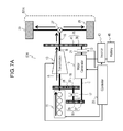
- FIG. 7A is a schematic view of the vehicle hybrid system according to Embodiment 1 for illustrating an operation during not assisting.
- FIG. 7B illustrates states of parts of the vehicle hybrid system according to Embodiment 1.
- FIG. 8A is a schematic view of the vehicle hybrid system according to Embodiment 1 for illustrating an operation during regeneration.
- FIG. 8B illustrates states of parts of the vehicle hybrid system according to Embodiment 1.
- FIG. 9 is a schematic view of a vehicle hybrid system according to Exemplary Embodiment 2.
- FIG. 10 is a schematic view of the vehicle hybrid system according to Embodiment 2.
- FIG. 11 is a schematic view of the vehicle hybrid system according to Embodiment 2 for illustrating an operation during the shifting of an operation point.
- FIG. 12 is a schematic view of the vehicle hybrid system according to Embodiment 2 for illustrating an operation during electric traveling.
- FIG. 13 is a schematic view of the vehicle hybrid system according to Embodiment 2 for illustrating an operation during regeneration.
- FIG. 14 is a schematic view of a power train system of a conventional hybrid vehicle.
- FIGS. 1 and 2 are schematic views of vehicle hybrid system 501 according to Exemplary Embodiment 1.
- vehicle hybrid system 501 includes engine 11 installed to vehicle 501 A, transmission 13 mechanically coupled with engine 11 , drive shaft 15 mechanically coupled with transmission 13 , motor generator 19 mechanically coupled with drive shaft 15 via both rotation-transmitting part 25 and power connecting-disconnecting part 20 , directional power transmission part 22 and rotation-transmitting part 16 both which mechanically couple between motor generator 19 and engine 11 , controller 23 electrically coupled with both motor generator 19 and power connecting-disconnecting part 20 .
- Directional power transmission part 22 is configured to transmit power in a direction from motor generator 19 to engine 11 to drive the engine while not to transmit power in a direction from engine 11 to motor generator 19 to drive the motor generator.
- transmission 13 and motor generator 19 are disposed in parallel with each other with respect to both drive shaft 15 and an output of engine 11 .
- This configuration allows controller 23 to control power connecting-disconnecting part 20 and motor generator 19 in power running and regeneration. Such control allows motor generator 19 to be directly coupled with drive shaft 15 while engine 11 can be started.
- This configuration provides efficient regeneration and power running while avoiding a loss in transmission 13 , hence providing high fuel efficiency.
- Transmission 13 includes input side 13 A and output side 13 B, and converts a rotational speed at input side 13 A into a rotational speed at output side 13 B. As shown in FIG. 2 , engine 11 is mechanically coupled with input side 13 A of transmission 13 .
- transmission 13 is a five-speed automatic transmission which includes a neutral stage and five transmission stages consisting of a first speed, a second speed, a third speed, a fourth speed, and a fifth speed.
- transmission 13 is not necessarily the five-speed automatic transmission, and may be a continuously variable transmission or a manual transmission.
- Output side 13 B of transmission 13 is mechanically coupled with tires 29 via drive shaft 15 and differential gear 27 .
- Gear 31 is coupled between engine 11 and input side 13 A of transmission 13 .
- Gear 31 is engaged with gear 33 .
- Gears 31 and 33 constitute rotation-transmitting part 16 .
- the gear ratio of gear 31 to gear 33 is 1:1.
- directional power transmission part 22 is one-way clutch 17 .
- One-way clutch 17 includes one end 17 A and other end 17 B which can be mechanically engaged and disengaged with each other.
- One end 17 A of one-way clutch 17 is mechanically coupled with gear 33 of rotation-transmitting part 16 .
- directional power transmission part 22 is not electrically coupled with controller 23 , the engaging and disengaging between one end 17 A and other end 17 B are automatically controlled in accordance with a direction and rotation speeds of one end 17 A and other end 17 B of one-way clutch 17 .
- Other end 17 B of one-way clutch 17 is mechanically coupled with gear 35 .
- Gear 35 is engaged with gear 37 .
- Gears 35 and 37 serving as a transmission part for changing the rotation speed constitute rotation-transmitting part 18 .
- a gear ratio of gear 35 to gear 37 is 5:1.
- Directional power transmission part 22 is not necessarily one-way clutch 17 , and may be a mechanical two-way clutch.
- the two-way clutch can transmit power in a direction from motor generator 19 to engine 11 to drive the engine while the clutch cannot transmit power in a direction from engine 11 to motor generator 19 to drive the motor generator.
- one-way clutch 17 can sufficiently perform the required function, and the one-way clutch has a simpler structure than the two-way clutch.
- directional power transmission part 22 is preferably implemented by one-way clutch 17 .
- Motor generator 19 is a double-shaft motor generator including one end 19 A and other end 19 B.
- One end 19 A of motor generator 19 is mechanically coupled with gear 37 .
- one end 19 A of motor generator 19 is mechanically coupled with engine 11 via rotation-transmitting part 18 , one-way clutch 17 , and rotation-transmitting part 16 .
- power connecting-disconnecting part 20 is implemented by clutch 21 .
- Clutch 21 includes one end 21 A and other end 21 B which can be mechanically engaged and disengaged with each other.
- One end 21 A of clutch 21 is mechanically coupled with other end 19 B of motor generator 19 .
- Power connecting-disconnecting part 20 is not necessarily clutch 21 , and may be a clutch, such as an electrically-controlled two-way clutch, including one end 21 A and other end 21 B which are mechanically engaged and disengaged under control of an external signal.
- An electrically-controlled two-way clutch may be suitably used in a case that high-speed responsivity is required.
- Input side 13 A of transmission 13 is mechanically coupled with one end 19 A of motor generator 19 via one-way clutch 17 while output side 13 B of transmission 13 is mechanically coupled with other end 19 B of motor generator 19 via clutch 21 .
- Both of rotation-transmitting part 18 and rotation-transmitting part 25 do not have a gear ratio of 1:1, thus each functioning as a transmission part to change a rotation speed. Therefore, according to Embodiment 1, the transmission part to change a rotation speed is disposed in each of both coupling paths, that is, one is a path from engine 11 via directional power transmission part 22 (one-way clutch 17 ) to motor generator 19 while the other is a path from motor generator 19 via power connecting-disconnecting part 20 (clutch 21 ) to drive shaft 15 .
- the gear ratios of these transmission parts may be appropriately determined in accordance with rotation characteristics of motor generator 19 , engine 11 , and transmission 13 .
- the configuration is not necessarily the configuration described above.
- the transmission part to change the rotation speed is disposed in at least one of two coupling paths, that is, one is the path from engine 11 via directional power transmission part 22 to motor generator 19 while the other is the path from motor generator 19 via power connecting-disconnecting part 20 to drive shaft 15 .
- the configuration can provide the same effects through an operation which will be described later.
- the configuration may not necessarily include the transmission part depending on the characteristics of motor generator 19 , engine 11 , and transmission 13 . However, since these components often have differences in characteristics, the transmission part is preferably used in the practical configuration as to offset their differences in characteristics with each other.
- Motor generator 19 can not only rotate ends 19 A and 19 B to generate a driving force upon having electric power supplied thereto, but also generate electric power upon having end 19 A or 19 B rotated with a rotational force externally supplied thereto.
- FIG. 3 illustrates correlation characteristics between a rotation speed and a torque generated by motor generator 19 upon functioning as a motor according to Embodiment 1.
- the generator operates as follows: The motor generator generates the maximum torque of 25 N ⁇ m while the rotation speed is smaller than 3000 rpm. The motor generator gradually reduces the torque as the rotation speed rises to a speed not smaller than 3000 rpm. The motor generator outputs a constant power at the rotation speed ranging from 3000 rpm to 6000 rpm. The upper limit of the rotation speed is 6000 rpm. The motor generator is prevented from operating as a motor when the rotation speed reaches 6000 rpm.
- Motor generator 19 can thus perform driving assistance (power running) of drive shaft 15 during traveling, and perform regeneration during braking in response to the traveling status of vehicle 501 A.
- motor generator 19 is electrically coupled via inverter 43 with battery 45 for storing the regenerated electric power.
- Controller 23 is electrically coupled with engine 11 , transmission 13 , motor generator 19 , clutch 21 , and inverter 43 . Controller 23 can acquire statuses of these devices and control their operations. Controller 23 is implemented by a microcomputer and a peripheral circuit including a memory. Then, controller 23 is also coupled with other in-vehicle apparatuses installed to vehicle 501 A, thereby performing operations, such as the acquisition of signals of an acceleration pedal and a brake pedal, concerning the traveling of vehicle 501 A.
- FIG. 4 is a schematic view of transmission 13 .
- transmission 13 is an automatic transmission which includes torque converter 47 associated with lock-up clutch 51 .
- an input from engine 11 to input side 13 A is input to torque converter 47 .
- the input is input to epicyclic gear set 49 in the post stage via torque converter 47 .
- the input from engine 11 is output from output side 13 B to drive shaft 15 having a rotation speed changed from that of the input.
- controller 23 controls the transmission such that lock-up clutch 51 is engaged in order to reduce a loss in torque converter 47 .
- the loss in torque converter 47 can be avoided even with conventional configurations; unfortunately, such avoidance is available only within a specific region.
- the transmission gear ratio at each transmission stage of transmission 13 is shown in Table 1.
- One-way clutch 17 can rotate only in the direction in which the rotation of motor generator 19 is transmitted to engine 11 , and cannot rotate in the direction in which the rotation of engine 11 is transmitted to motor generator 19 . That is, as shown in FIG. 2 , when a rotation speed RE at point E (end 17 B coupled with motor generator 19 ) is not smaller than a rotation speed RA at point A (end 17 A coupled with engine 11 ), one-way clutch 17 is engaged to couple between ends 17 A and 17 B. When the rotation speed RE at point E is smaller than the rotation speed RA at point A, ends 17 A and 17 B are disconnected from each other to cause one-way clutch 17 to race.
- clutch 21 is configured such that an external signal can control the connection and disconnection between ends 21 A and 21 B. According to Embodiment 1, clutch 21 is controlled by controller 23 .
- FIGS. 5 to 7A are schematic views of vehicle hybrid system 501 for illustrating the operations thereof.
- FIG. 7B shows the statuses of parts during the starting of engine 11 , acceleration, and traveling at a constant speed.
- controller 23 When a driver presses down an acceleration pedal to generate a signal of an acceleration command, controller 23 receives the signal. Upon receiving the signal, controller 23 first drives motor generator 19 to rotate engine 11 to start since one-way clutch 17 is engaged. Simultaneously to this, point A rotates as well, so that the driving force is transmitted to drive shaft 15 , thereby eventually driving tires 29 to cause vehicle 501 A to start moving at a low speed.
- engine 11 upon being a 3-liter class V-6 engine, for example, requires a torque for starting engine 11 is about 100 N ⁇ m.
- the maximum torque of motor generator 19 is 25 N ⁇ m as shown in FIG. 3 .
- the torque of motor generator 19 is multiplied by five to rotate engine 11 .
- a starting torque of 125 N ⁇ m is applied to engine 11 .
- Vehicle hybrid system 501 according to Embodiment 1 can thus start engine 11 sufficiently.
- controller 23 drives motor generator 19 while clutch 21 is disengaged.
- Controller 23 starts engine 11 as follows. First, the rotation speed of engine 11 increases.
- engine 11 is a direct-injection engine, for example, when either the first or the second cylinder of the engine reaches the compression top dead center, fuel is directly injected into the cylinder. Immediately after the injection, the mixture of air and the injected fuel is combusted with a spark plug, thereby starting engine 11 . After that, a mode in which vehicle 501 A is traveled with motor generator 19 is shifted to a mode in which vehicle 501 A is traveled with engine 11 . The situation of this operation is shown in FIG. 5 .
- Engine 11 is thus started by the driving force generated by motor generator 19 , similarly to a push start, for the speed of the vehicle ranging from 0 (zero) to 2 km/h.
- the rotation speed RC at point C motor generator 19 ranges from 0 (zero) to 3000 rpm in which the motor generator can generate the maximum torque enough to start engine 11 .
- the rotation speed RB (point B) of drive shaft 15 is uniquely determined to be 50 rpm based on a fixed reduction gear ratio of differential gear 27 .
- the rotation speed RA (point A) of engine 11 would intrinsically be 200 rpm that is four times the rotation speed RB (point B). However, torque converter 47 rotates while slipping since lock-up clutch 51 inside transmission 13 is disengaged. In FIG. 7B , the slip ratio in this case is 3.0; therefore, the net result is that the rotation speed RA (point A) of engine 11 is 600 rpm.
- motor generator 19 applies the torque to transmission 13 via rotation-transmitting part 18 , one-way clutch 17 , and rotation-transmitting part 16 , thereby driving tires 29 via drive shaft 15 and differential gear 27 , which assists the running of vehicle 501 A.
- the rotation speed RC (point C) of motor generator 19 is 3000 rpm based on the gear ratio of 5:1 of rotation-transmitting part 18 .
- the rotation speed RD at point D is 150 rpm which is driven by drive shaft 15 via rotation-transmitting part 25 .
- Rotation speed RD is smaller than the rotation speed RC (point C) of 3000 rpm of motor generator 19 , but does not cause any inconsistency between rotation speeds RD and RC since clutch 21 is disengaged at this moment.
- controller 23 causes motor generator 19 to reduce the rotation speed of the motor generator.
- clutch 21 is engaged to apply the output of motor generator 19 to drive shaft 15 via rotation-transmitting part 25 , thereby driving tires 29 .
- the rotation speed RD at point D is determined as shown in FIG. 7B based on the rotation speed RB (point B) of drive shaft 15 .
- the rotation speed RA at point A would intrinsically be 400 rpm.
- lock-up clutch 51 is still disengaged, and allows the torque converter to slip at a slip ratio of 2.0. Therefore, the net result is that the rotation speed RA (point A) of engine 11 is 800 rpm.
- motor generator 19 can generate a torque up to the maximum torque of 25 N ⁇ m at the rotation speed of 300 rpm.
- the torque is multiplied by three by rotation-transmitting part 25 , and is transmitted to drive shaft 15 .
- controller 23 controls lock-up clutch 51 such that lock-up clutch 51 is engaged at middle-to-high speeds to eliminate the slipping between engine 11 and transmission 13 , thereby increasing efficiency.
- controller 23 disengages lock-up clutch 51 and utilizes a shock dampening function of torque converter 47 to reduce, e.g. gear-shift shocks and micro-vibrations attributed to torsional vibrations of the drive-train.
- motor generator 19 performs power running to assist drive shaft 15 .
- torque converter 47 changes both the transmission stage and the rotation-speed reduction ratio due to slipping, which results in the rotation speed of each part, as shown in FIG. 7B .
- the rotation speed RD at point D is 4500 rpm. Therefore, as shown in FIG. 3 , the higher the speed of the vehicle increases, the smaller the torque transmitted to drive shaft 15 is.
- the amount of energy regenerated as described later decreases from the amount of physical kinetic energy of vehicle 501 A, which is attributed to total mechanical-electrical transmission efficiency.
- the running energy also decreases due to the total mechanical-electrical transmission efficiency. That is, the amount of mechanical energy output from the tires is smaller than the amount of electrical energy stored in the battery. Therefore, from a viewpoint of energy balance between the regeneration and the power running, controller 23 determines that the upper limit of the speed of the vehicle is lower in the power running than in the regeneration.
- controller 23 disengages clutch 21 to halt the power running of motor generator 19 .
- the driving force is transmitted from engine 11 via transmission 13 and drive shaft 15 to tires 29 , as denoted by thick arrows shown in FIG. 7A .
- controller 23 may continuously cause motor generator 19 to assist drive shaft 15 at, e.g. hard acceleration.
- the transmission stage of transmission 13 is shifted to the fifth speed, and the transmission gear ratio is 0.8:1 (overdrive gear ratio) according to Table 1. Accordingly, although the rotation speed of engine 11 is 2000 rpm, the rotation speed of drive shaft 15 is 2500 rpm. At this moment, if clutch 21 is engaged, based on the gear ratio of 3 (three) of rotation-transmitting part 25 , the rotation speed RD at point D is 7500 rpm. This rotation speed exceeds the upper limit (6000 rpm) of the rotation speed of motor generator 19 , which causes the counter electromotive voltage to exceed the battery voltage, resulting in an overvoltage applied to battery 45 .
- controller 23 performs the following control.
- a predetermined vehicle speed 80 km/h according to Embodiment 1
- the controller disengages clutch 21 and causes motor generator 19 to halt the power running.
- the controller engages clutch 21 and causes motor generator 19 to perform the power running.
- the predetermined speed of the vehicle described above is not necessarily the speed of the vehicle at which the counter electromotive voltage exceeds the battery voltage.
- the predetermined speed may be appropriately determined in accordance with the state of control of clutch 21 and/or motor generator 19 , based on a parameter, such as efficiency reduction parameter depending on the rotation speed, with the parameter obtained via field-weakening control.
- Vehicle 501 A is thus accelerated.
- controller 23 controls vehicle hybrid system 501 based on the statuses shown in FIG. 7B in accordance with the speed of the vehicle.
- controller 23 engages clutch 21 and drives motor generator 19 while the speed of the vehicle rises from 0 (zero) to a predetermined speed, whereas the controller disengages clutch 21 and halts motor generator 19 from operating when the speed of the vehicle exceeds the predetermined speed.
- FIG. 8A is a schematic view of vehicle hybrid system 501 for illustrating the operation of vehicle hybrid system 501 during the deceleration.
- FIG. 8B shows the statuses of parts of vehicle hybrid system 501 during the deceleration of vehicle 501 A.
- the rotation speed (6000 rpm) of motor generator 19 is divided by 5 (five) due to rotation-transmitting part 18 ; therefore, the rotation speed RE at point E of end 17 A of one-way clutch 17 is 1200 rpm.
- the rotation speed RE is smaller than the rotation speed of engine 11 , so that one-way clutch 17 is disengaged and transmits no torque.
- engine 11 is not required to output any driving force, so that the engine may be usually subjected to fuel cut-off for improving fuel efficiency. This operation allows vehicle 501 A to travels in an inertial traveling state, i.e. so-called coasting.
- a flow of the driving force in this case is denoted by thick arrows shown in FIG. 8A .
- the rotation force of drive shaft 15 which is rotated via tires 29 is input to motor generator 19 via both rotation-transmitting part 25 and clutch 21 allows motor generator 19 to generate regenerative electric power.
- This regenerative electric power is stored in battery 45 via inverter 43 .
- Drive shaft 15 is also coupled with transmission 13 .
- FIG. 8B at a speed of the vehicle of 80 km/h, the transmission stage is the fifth speed and lock-up clutch 51 is engaged; therefore, the rotation input to transmission 13 is also transmitted to engine 11 .
- engine 11 is subjected to the fuel cut-off as described above, so that the engine is merely rotated by drive shaft 15 .
- controller 23 shifts transmission 13 to neutral and disengages clutch 21 , thereby causing motor generator 19 to halt the generation of the regenerative electric power.
- This state is the same as that shown in FIG. 2 .
- both the rotation speed RA at point A and the rotation speed RE at point E are equal to each other, 0 (zero) rpm; therefore, one-way clutch 17 can be engaged immediately.
- drive shaft 15 still rotates, so that the rotation speeds RB and RD at points B and D are not 0 (zero) rpm.
- controller 23 still continuously allows the speed of the vehicle to be 4 km/h, which brings the speed of the vehicle to be 0 (zero) km/h, with rotation speeds of all the points A to E being 0 (zero) rpm, i.e. a halt.
- controller 23 engages clutch 21 and causes motor generator 19 to generate the regenerative electric power when the rotation speed of motor generator 19 is not larger than the upper limit of the rotation speed thereof, whereas the controller disengages clutch 21 and halts motor generator 19 from operating when the speed of vehicle 501 A reaches the lower limit of the speed of the vehicle.
- controller 23 may shift transmission 13 to neutral to reduce the loss in engine 11 . Moreover, controller 23 may additionally disengage clutch 21 as well, thereby halting motor generator 19 from generating the regenerative electric power, resulting in a further longer distance can be traveled due to the coasting.
- This control causes the rotation speed RA (point A) of engine 11 to be 0 (zero) rpm. Hence, when engine 11 is restarted by pressing down the acceleration pedal, motor generator 19 rotates. This operation, since the rotation speed RA at point A is 0 (zero) rpm, one-way clutch 17 is engaged. This allows motor generator 19 to drive engine 11 , thereby immediately restarting the engine.
- controller 23 may shift transmission 13 to neutral, engage clutch 21 , and extract no regenerative electric power generated by motor generator 19 .
- engine 11 is rotated by drive shaft 15 via motor generator 19 that is disposed in parallel with transmission 13 .
- the rotation speed of the engine is smaller when the engine is driven via the motor generator than when the engine is driven via transmission 13 , thereby reducing a loss in engine 11 .
- This operation increases the distance which vehicle 501 A can travel due to coasting.
- engine 11 is continuously rotated by drive shaft 15 via motor generator 19 .
- the vehicle can immediately shift to the mode of traveling by engine 11 , only by carrying out fuel injection and ignition. It is also possible to avoid a loss of the negative pressure in the break system which uses a negative air-pressure booster, enhancing safety.
- controller 23 disengages clutch 21 to cut off motor generator 19 . Then, similarly to usual vehicles, the reverse gear of transmission 13 is selected, thereby causing vehicle 501 A to travel reversely by engine 11 . Alternatively, controller 23 may shift transmission 13 to neutral and cause motor generator 19 to rotate reversely, thereby causing vehicle 501 A to travel reversely. In this case, one-way clutch 17 rotates at idle because of the reverse rotation of motor generator 19 . Moreover, motor generator 19 for reverse traveling allows an effective use of the regenerative energy.
- controller 23 When engine 11 is started, controller 23 disengages power connecting-disconnecting part 20 and then causes motor generator 19 to perform power running, thereby starting engine 11 via directional power transmission part 22 . Simultaneously to this, the controller also drives transmission 13 to rotate drive shaft 15 .
- controller 23 engages power connecting-disconnecting part 20 and then causes motor generator 19 to perform power running, thereby rotating drive shaft 15 via power connecting-disconnecting part 20 to drive vehicle 501 A.
- controller 23 engages power connecting-disconnecting part 20 and then causes motor generator 19 to generate regenerative electric power.
- transmission 13 and motor generator 19 are mechanically disposed in parallel with each other. Then, clutch 21 on output side 13 B of transmission 13 is engaged in accordance with the conditions of the power running and regeneration, as described above. The engaging of the clutch allows the power running and regeneration stresses of motor generator 19 to be transmitted directly drive shaft 15 . Therefore, this operation eliminates a loss in transmission 13 , providing vehicle hybrid system 501 with high efficiency.
- FIGS. 9 and 10 are schematic views of vehicle hybrid system 502 according to Exemplary Embodiment 2.
- components identical to those of vehicle hybrid system 501 shown in FIGS. 1 and 2 according to Embodiment 1 are designated by the same reference numerals.
- vehicle hybrid system 502 includes engine 11 installed to vehicle 501 A, transmission 13 mechanically coupled with engine 11 , drive shaft 15 mechanically coupled with transmission 13 , motor generator 19 mechanically coupled with drive shaft 15 via both transmission-output-side rotation-transmitting part 75 and power connecting-disconnecting part 70 , power connecting-disconnecting part 72 mechanically coupled with motor generator 19 , transmission-input-side rotation-transmitting part 66 mechanically coupling between power connecting-disconnecting part 72 and engine 11 , and controller 23 electrically coupled with power connecting-disconnecting part 70 , motor generator 19 , and power connecting-disconnecting part 72 .
- transmission 13 and motor generator 19 are disposed in parallel with each other with respect to both drive shaft 15 and the output of engine 11 .
- This configuration allows controller 23 to control power connecting-disconnecting part 70 , power connecting-disconnecting part 72 , and motor generator 19 in power running and regeneration.
- Such control allows motor generator 19 to be directly coupled with drive shaft 15 while engine 11 can started.
- This configuration allows the highly efficient regeneration and power running while a loss in transmission 13 is avoided, hence providing high fuel efficiency.
- vehicle hybrid system 502 The configuration and operations of vehicle hybrid system 502 according to Embodiment 2 will be detailed below.
- vehicle hybrid system 502 according to Embodiment 2 includes power connecting-disconnecting part 72 (clutch 67 ) instead of directional power transmission part 22 (one-way clutch 17 ) of vehicle hybrid system 501 according to Embodiment 1.
- Clutch 67 can be engaged and disengaged under control from the outside.
- the configuration of clutch 71 is identical to that of clutch 21 .
- Controller 23 can engage and disengage clutches 67 and 71 independently of each other.
- At least one of power connecting-disconnecting part 70 (clutch 71 ) and power connecting-disconnecting part 72 (clutch 67 ) may be an electrically-controlled two-way clutch.
- an external signal can select, e.g. operation modes concerning an idle rotation and a direction of rotation. Therefore, various controls of vehicle hybrid systems 502 according to Embodiment 2, which will be described later, can be easily performed with a simple configuration.
- vehicle hybrid system 502 according to Embodiment 2 does not include rotation-transmitting part 18 of vehicle hybrid system 501 according to Embodiment 1.
- Vehicle hybrid system 501 according to Embodiment 1 includes rotation-transmitting part 18 for reducing the rotation speed since one-way clutch 17 can hardly follow high rotational speeds.
- Vehicle hybrid system 502 is identical to that of vehicle hybrid system 501 according to Embodiment 1 with the above exceptions.
- Vehicle hybrid system 502 according to Embodiment 2 includes transmission-input-side rotation-transmitting part 66 including gears 81 and 83 , instead of rotation-transmitting part 16 including gears 31 and 33 of vehicle hybrid system 501 according to Embodiment 1.
- Configurations of gears 81 and 83 are similar to those of gears 31 and 33 , respectively.
- Vehicle hybrid system 502 according to Embodiment 2 includes transmission-output-side rotation-transmitting part 75 including gears 89 and 91 , instead of rotation-transmitting part 25 including gears 39 and 41 of vehicle hybrid system 501 according to Embodiment 1.
- Configurations of gears 89 and 91 are similar to those of gears 39 and 41 , respectively. These parts constitute a transmission part with a function of changing the rotation speed.
- One of rotation-transmitting parts 25 and 75 may constitute the transmission part while the other may constitute a part without a function of changing the rotation speed. That is, the transmission part is disposed in at least one of two coupling paths, that is, a path from engine 11 via power connecting-disconnecting part 70 to motor generator 19 , and a path from motor generator 19 via power connecting-disconnecting part 72 to drive shaft 15 .
- the transmission part may be configured appropriately in accordance with rotation characteristics of motor generator 19 , engine 11 , and transmission 13 .
- a configuration without any transmission part is also possible depending on the rotation characteristics of motor generator 19 , engine 11 , and transmission 13 . In practical cases, however, the configuration preferably includes the transmission part in order to match their characteristics different with each other.
- vehicle hybrid system 502 An operation of vehicle hybrid system 502 will be described below.
- basic operations of vehicle hybrid system 502 according to Embodiment 1 are identical to those according to Embodiment 1 since the configuration of the former system is identical to that of the latter system except that clutch 67 is disposed in the former instead of one-way clutch 17 disposed in the latter.
- Controller 23 engages and disengages clutch 67 similarly to one-way clutch 17 of vehicle hybrid system 501 according to Embodiment 1.
- controller 23 When engine 11 is started, controller 23 disengages power connecting-disconnecting part 70 and engages power connecting-disconnecting part 72 . Then, the controller causes motor generator 19 to perform power running, which causes engine 11 to start via power connecting-disconnecting part 72 . Simultaneously, motor generator 19 also drives transmission 13 to rotate drive shaft 15 .
- Controller 23 engages power connecting-disconnecting part 70 , disengages power connecting-disconnecting part 72 , and then, causes motor generator 19 to perform power running. This operation allows motor generator 19 to rotate drive shaft 15 via power connecting-disconnecting part 70 , thereby driving vehicle 501 A.
- controller 23 engages power connecting-disconnecting part 70 , disengages power connecting-disconnecting part 72 , and then, causes motor generator 19 to generate regenerative electric power.
- Vehicle hybrid system 502 thus performs the basic operations identical to those of vehicle hybrid system 501 according to Embodiment 1, which allows motor generator 19 to perform all the operations in starting of the engine, power running, and regeneration. This improves efficiency similarly to vehicle hybrid system 501 according to Embodiment 1.
- vehicle hybrid system 502 according to Embodiment 2 will be detained below.
- FIG. 11 is a schematic view of vehicle hybrid system 502 for illustrating the operation of shifting the operation point.
- controller 23 engages clutch 67 and disengages clutch 71 , thereby allowing motor generator 19 to generate electricity such that the rotation speed and the torque of engine 11 provides high efficiency of engine 11 .
- controller 23 sends engine 11 an output command for the engine to output power additionally includes extra power accordingly necessary to the generation of electricity by motor generator 19 .
- engine 11 outputs the torque which is the sum of a torque due to the running resistance and an additional torque necessary for the generation of electricity by motor generator 19 . Accordingly, an operating point is shifted such that a load operating point shifts to higher loads. Consequently, vehicle hybrid system 502 as a whole can improve efficiency.
- the generated electric power is stored in battery 45 via inverter 43 to be used again as energy for power running.
- FIG. 12 is a schematic view of vehicle hybrid system 502 for illustrating the operation with vehicle 501 A traveling by the electric power.
- Controller 23 disengages clutch 67 , engages clutch 71 , shifts transmission 13 to neutral, and then, drives motor generator 19 , which allows vehicle 501 A to travel electrically.
- the vehicle travels at low speeds for example, the vehicle travels only by electricity without starting engine 11 , hence reducing fuel consumption in according to this operation.
- the above control can assist the traveling in coasting. This operation increases a distance that can be traveled by coasting, accordingly reducing fuel consumption.
- FIG. 13 is a schematic view of the vehicle hybrid system according to Embodiment 2 for illustrating the operation during regeneration.
- vehicle hybrid system 501 according to Embodiment 1 when the vehicle is decelerated, one-way clutch 17 is engaged during regeneration depending on conditions as shown in the columns of FIG. 8B which involve speeds of the vehicle of 40, 20, and 10 km/h.
- one-way clutch 17 When one-way clutch 17 is engaged, the rotation of one-way clutch 17 is transmitted to engine 11 , resulting in the occurrence of an additional loss according to the rotation of engine 11 .
- controller 23 can cause all the rotation of tires 29 to be input to motor generator 19 by disengaging clutch 67 , engaging clutch 71 , and shifting transmission 13 to neutral. As a result, a loss in engine 11 is avoided, resulting in highly efficient regeneration with the avoided loss.
- Vehicle hybrid system 502 according to Embodiment 2 can perform operations for shifting the operation point, electric traveling, and efficient regeneration in addition to operations of vehicle hybrid system 501 according to Embodiment 1, further enhancing efficiency.
- transmission 13 and motor generator 19 are mechanically disposed in parallel with each other.
- Clutches 67 and 71 which are coupled with input side 13 A and output side 13 B of transmission 13 respectively are engaged and disengaged independently in accordance with conditions of power running and regeneration.
- Such controls allow direct transmission of both power running and regeneration stresses of motor generator 19 .
- a loss in transmission 13 can be avoided, leading to efficient vehicle hybrid system 502 .
- each of the rotation-transmitting parts may be implemented by pulleys together with a belt or chain while they can slip over time. For this reason, the gears are preferably used from an efficiency point of view.
- directional power transmission part 22 or power connecting-disconnecting part 72 is mechanically coupled with the coupling part between one end of engine 11 and transmission 13 .
- the directional power transmission part or the power connecting-disconnecting part may be coupled with the other end of engine 11 .
- a part may be separately disposed for an exclusive use in taking out the output.
- motor generator 19 has a double-shaft structure, i.e. a structure with two shafts on both sides which includes shafts 19 A and 19 B.
- motor generator 19 may have a single-shaft structure.
- the end of the single shaft may be equipped with a rotation-transmitting part implemented by, e.g. gears to split the rotation of the shaft. This configuration allows the shingle-shaft structure to be used as well as the double-shaft structure.
- a vehicle hybrid system according to the present invention has a configuration in which a motor generator is disposed in parallel with a transmission, hence having high efficiency, and is useful particularly for vehicle hybrid systems each including an engine and a motor generator.
Landscapes
- Engineering & Computer Science (AREA)
- Transportation (AREA)
- Mechanical Engineering (AREA)
- Chemical & Material Sciences (AREA)
- Combustion & Propulsion (AREA)
- Power Engineering (AREA)
- Automation & Control Theory (AREA)
- Hybrid Electric Vehicles (AREA)
- Electric Propulsion And Braking For Vehicles (AREA)
- Control Of Driving Devices And Active Controlling Of Vehicle (AREA)
Applications Claiming Priority (3)
| Application Number | Priority Date | Filing Date | Title |
|---|---|---|---|
| JP2014-030316 | 2014-02-20 | ||
| JP2014030316 | 2014-02-20 | ||
| PCT/JP2015/000107 WO2015125407A1 (ja) | 2014-02-20 | 2015-01-13 | 車両用ハイブリッドシステム |
Publications (2)
| Publication Number | Publication Date |
|---|---|
| US20160272187A1 US20160272187A1 (en) | 2016-09-22 |
| US10046753B2 true US10046753B2 (en) | 2018-08-14 |
Family
ID=53877936
Family Applications (1)
| Application Number | Title | Priority Date | Filing Date |
|---|---|---|---|
| US15/032,657 Active 2035-05-11 US10046753B2 (en) | 2014-02-20 | 2015-01-13 | Vehicle hybrid system |
Country Status (4)
| Country | Link |
|---|---|
| US (1) | US10046753B2 (ja) |
| EP (1) | EP3109111B1 (ja) |
| JP (1) | JP6573201B2 (ja) |
| WO (1) | WO2015125407A1 (ja) |
Cited By (2)
| Publication number | Priority date | Publication date | Assignee | Title |
|---|---|---|---|---|
| US10322713B2 (en) * | 2014-04-11 | 2019-06-18 | Renault S.A.S. | Method for controlling a hybrid transmission for a motor vehicle taking into account transition interruptions between kinematic modes |
| US11603925B1 (en) * | 2021-11-30 | 2023-03-14 | GM Global Technology Operations LLC | Hydraulically actuated clutch system and control logic for torque converter assemblies |
Families Citing this family (19)
| Publication number | Priority date | Publication date | Assignee | Title |
|---|---|---|---|---|
| JP2017094854A (ja) * | 2015-11-20 | 2017-06-01 | トヨタ自動車株式会社 | 車両駆動装置 |
| CN106608175A (zh) * | 2016-10-26 | 2017-05-03 | 联合汽车电子有限公司 | 混合动力汽车动力系统及其动力传动方法 |
| CN106608178A (zh) * | 2016-10-26 | 2017-05-03 | 联合汽车电子有限公司 | 混合动力汽车的动力系统及其动力传动方法 |
| CN106608176A (zh) * | 2016-10-26 | 2017-05-03 | 联合汽车电子有限公司 | 混合动力汽车动力系统及其动力传动方法 |
| JP6669058B2 (ja) * | 2016-12-27 | 2020-03-18 | トヨタ自動車株式会社 | 車両用駆動装置 |
| DE102017208249A1 (de) * | 2017-05-16 | 2018-11-22 | Volkswagen Aktiengesellschaft | Kraftfahrzeug-Antriebsstrang mit Freilauf aufweisendem Getriebe |
| DE102018201370B4 (de) * | 2018-01-30 | 2023-10-26 | Magna powertrain gmbh & co kg | Antriebsstrang für ein Hybridfahrzeug |
| CN109080429A (zh) * | 2018-09-26 | 2018-12-25 | 特百佳动力科技有限公司 | 商用车用混合动力系统、控制方法及商用车 |
| CN109649149B (zh) * | 2019-01-16 | 2024-02-09 | 无锡商业职业技术学院 | 一种能量溢出工况下双电机同时回收的混合动力传动系统 |
| CN111634281A (zh) * | 2019-10-25 | 2020-09-08 | 长城汽车股份有限公司 | 车辆的能量回收控制方法及装置 |
| GB2594286B8 (en) * | 2020-04-21 | 2024-05-22 | Jaguar Land Rover Ltd | Apparatus and method for controlling an electric machine |
| GB2594282B (en) * | 2020-04-21 | 2022-09-07 | Jaguar Land Rover Ltd | Apparatus and method for controlling an electric machine |
| GB2594280B (en) * | 2020-04-21 | 2022-10-05 | Jaguar Land Rover Ltd | Apparatus and method for controlling an electric machine |
| CN111775685B (zh) * | 2020-07-14 | 2022-02-18 | 中国第一汽车股份有限公司 | 一种后驱混合动力车辆的驱动系统 |
| JP6921287B1 (ja) * | 2020-09-04 | 2021-08-18 | ▲福衛▼ 澤田 | クラッチ装置及び衝突緩和機構 |
| WO2022124275A1 (ja) * | 2020-12-07 | 2022-06-16 | 愛知製鋼株式会社 | 電気駆動移動体用ギアードモータ |
| JP7709300B2 (ja) * | 2021-04-28 | 2025-07-16 | 株式会社Subaru | 車両用駆動装置 |
| CN115003531A (zh) * | 2021-07-19 | 2022-09-02 | 华为数字能源技术有限公司 | 电动汽车驱动系统和电动汽车 |
| US20240016075A1 (en) * | 2022-07-15 | 2024-01-18 | Cnh Industrial America Llc | Vehicle kick to neutral control |
Citations (10)
| Publication number | Priority date | Publication date | Assignee | Title |
|---|---|---|---|---|
| JPH0195944A (ja) | 1987-10-07 | 1989-04-14 | Aisin Aw Co Ltd | ハイブリッド車両の動力伝達装置 |
| US5549524A (en) * | 1994-10-03 | 1996-08-27 | Yang; Tai-Her | Multiple functioned combined power system |
| JP2004122925A (ja) | 2002-10-02 | 2004-04-22 | Kokusan Denki Co Ltd | ハイブリッド自動二輪車及びハイブリッド自動二輪車用動力伝達装置 |
| JP2005271669A (ja) | 2003-04-16 | 2005-10-06 | Tai-Her Yang | エンジン駆動オートバイの電動後進補助システム |
| JP3890803B2 (ja) | 1999-04-12 | 2007-03-07 | トヨタ自動車株式会社 | ハイブリッド車両の動力伝達装置 |
| EP1792800A2 (en) | 2005-11-09 | 2007-06-06 | Nissan Motor Co., Ltd. | Hybrid vehicle control |
| US20100258367A1 (en) | 2007-10-10 | 2010-10-14 | Venturi Stephane | Travel drive system with multiple transmission paths for hybrid vehicle and method using same |
| JP2012240623A (ja) | 2011-05-24 | 2012-12-10 | Jatco Ltd | ハイブリッド駆動装置 |
| JP5169433B2 (ja) | 2008-04-21 | 2013-03-27 | 日産自動車株式会社 | ハイブリッド車両の発電制御方法 |
| EP2682293A1 (en) | 2012-07-03 | 2014-01-08 | FERRARI S.p.A. | Automatic manual transmission for a hybrid car provided with an internal combustion engine and with an electrical machine |
Family Cites Families (12)
| Publication number | Priority date | Publication date | Assignee | Title |
|---|---|---|---|---|
| JP3441198B2 (ja) * | 1994-10-25 | 2003-08-25 | 株式会社エクォス・リサーチ | ハイブリッド車両 |
| JP3411522B2 (ja) * | 1999-04-13 | 2003-06-03 | ダイハツ工業株式会社 | 自動車のモータアシスト駆動装置 |
| JP4499084B2 (ja) * | 2000-03-10 | 2010-07-07 | 日立オートモティブシステムズ株式会社 | 自動車用自動変速機、およびそれを用いた自動車 |
| JP3677733B2 (ja) * | 2000-04-06 | 2005-08-03 | ジヤトコ株式会社 | パラレルハイブリッド車両 |
| JP2004357443A (ja) * | 2003-05-30 | 2004-12-16 | Toyoda Mach Works Ltd | 蓄電手段回生回路、車両駆動回生装置及び車両 |
| JP5456263B2 (ja) * | 2007-05-02 | 2014-03-26 | 日産自動車株式会社 | ハイブリッド車両の駆動制御装置 |
| US7972235B2 (en) * | 2007-10-11 | 2011-07-05 | GM Global Technology Operations LLC | Hybrid powertrain system having selectively connectable engine, motor/generator, and transmission |
| CN102459957B (zh) * | 2009-06-24 | 2015-05-06 | 菲斯科汽车科技集团有限公司 | 用于高混合动力串联/并联高速电机驱动系统的驱动配置 |
| JP2011131829A (ja) * | 2009-12-25 | 2011-07-07 | Mitsubishi Fuso Truck & Bus Corp | ハイブリッド電気自動車の制御装置 |
| JP2011255706A (ja) * | 2010-06-04 | 2011-12-22 | Honda Motor Co Ltd | ハイブリッド車両の駆動装置 |
| JP5648428B2 (ja) * | 2010-11-02 | 2015-01-07 | アイシン精機株式会社 | ハイブリッド車両の変速装置 |
| JP5467197B2 (ja) * | 2011-05-24 | 2014-04-09 | ジヤトコ株式会社 | ハイブリッド駆動装置 |
-
2015
- 2015-01-13 JP JP2016503955A patent/JP6573201B2/ja not_active Expired - Fee Related
- 2015-01-13 EP EP15751997.6A patent/EP3109111B1/en active Active
- 2015-01-13 US US15/032,657 patent/US10046753B2/en active Active
- 2015-01-13 WO PCT/JP2015/000107 patent/WO2015125407A1/ja not_active Ceased
Patent Citations (13)
| Publication number | Priority date | Publication date | Assignee | Title |
|---|---|---|---|---|
| JPH0195944A (ja) | 1987-10-07 | 1989-04-14 | Aisin Aw Co Ltd | ハイブリッド車両の動力伝達装置 |
| US5549524A (en) * | 1994-10-03 | 1996-08-27 | Yang; Tai-Her | Multiple functioned combined power system |
| JP3890803B2 (ja) | 1999-04-12 | 2007-03-07 | トヨタ自動車株式会社 | ハイブリッド車両の動力伝達装置 |
| JP2004122925A (ja) | 2002-10-02 | 2004-04-22 | Kokusan Denki Co Ltd | ハイブリッド自動二輪車及びハイブリッド自動二輪車用動力伝達装置 |
| JP2005271669A (ja) | 2003-04-16 | 2005-10-06 | Tai-Her Yang | エンジン駆動オートバイの電動後進補助システム |
| EP1792800A2 (en) | 2005-11-09 | 2007-06-06 | Nissan Motor Co., Ltd. | Hybrid vehicle control |
| US20100258367A1 (en) | 2007-10-10 | 2010-10-14 | Venturi Stephane | Travel drive system with multiple transmission paths for hybrid vehicle and method using same |
| JP2011501713A (ja) | 2007-10-10 | 2011-01-13 | イエフペ エネルジ ヌヴェル | ハイブリッド乗り物用の複数の伝達経路を有している走行駆動装置とこれを用いる方法 |
| JP5169433B2 (ja) | 2008-04-21 | 2013-03-27 | 日産自動車株式会社 | ハイブリッド車両の発電制御方法 |
| JP2012240623A (ja) | 2011-05-24 | 2012-12-10 | Jatco Ltd | ハイブリッド駆動装置 |
| JP5395115B2 (ja) | 2011-05-24 | 2014-01-22 | ジヤトコ株式会社 | ハイブリッド駆動装置 |
| EP2682293A1 (en) | 2012-07-03 | 2014-01-08 | FERRARI S.p.A. | Automatic manual transmission for a hybrid car provided with an internal combustion engine and with an electrical machine |
| US20140011631A1 (en) | 2012-07-03 | 2014-01-09 | Ferrari S.P.A. | Automatic manual transmission for a hybrid car provided with an internal combustion engine and with an electrical machine |
Non-Patent Citations (2)
| Title |
|---|
| International Search Report of PCT application No. PCT/JP2015/000107 dated Apr. 21, 2015. |
| The Extended European Search Report dated Feb. 10, 2017 for the related European Patent Application No. 15751997.6. |
Cited By (2)
| Publication number | Priority date | Publication date | Assignee | Title |
|---|---|---|---|---|
| US10322713B2 (en) * | 2014-04-11 | 2019-06-18 | Renault S.A.S. | Method for controlling a hybrid transmission for a motor vehicle taking into account transition interruptions between kinematic modes |
| US11603925B1 (en) * | 2021-11-30 | 2023-03-14 | GM Global Technology Operations LLC | Hydraulically actuated clutch system and control logic for torque converter assemblies |
Also Published As
| Publication number | Publication date |
|---|---|
| EP3109111A1 (en) | 2016-12-28 |
| EP3109111B1 (en) | 2019-08-28 |
| WO2015125407A1 (ja) | 2015-08-27 |
| JPWO2015125407A1 (ja) | 2017-03-30 |
| EP3109111A4 (en) | 2017-03-15 |
| JP6573201B2 (ja) | 2019-09-11 |
| US20160272187A1 (en) | 2016-09-22 |
Similar Documents
| Publication | Publication Date | Title |
|---|---|---|
| US10046753B2 (en) | Vehicle hybrid system | |
| US8661941B2 (en) | Hybrid drive system | |
| RU2653656C2 (ru) | Устройство для определения неисправностей гибридного транспортного средства и соответствующий способ определения неисправностей | |
| RU2640164C1 (ru) | Транспортное средство | |
| CN102328578B (zh) | 用于机动车辆的驱动系统及具有这种驱动系统的机动车辆 | |
| KR101704173B1 (ko) | 하이브리드 차량용 구동 장치의 제어 장치 | |
| US9199637B1 (en) | Engine autostop control system and method for hybrid powertrain | |
| US9156344B2 (en) | Motor-assisted transmission | |
| US20080214352A1 (en) | Motor vehicle drive train and method for controlling a drive train | |
| US9393953B2 (en) | Transmission for vehicle and control device | |
| CN102971168A (zh) | 传动系 | |
| US9487205B2 (en) | Controller of hybrid system | |
| US9932040B2 (en) | Hybrid car | |
| WO2014091588A1 (ja) | ハイブリッド車両の制御装置 | |
| US9156461B2 (en) | Vehicle control unit | |
| JP7000277B2 (ja) | 車両の制御装置 | |
| US8419591B2 (en) | Vehicle drive system | |
| KR102440598B1 (ko) | 마일드 하이브리드 차량의 변속 클러치 제어 방법 및 장치 | |
| CN205239482U (zh) | 一种车用混合动力总成 | |
| WO2015076230A1 (ja) | ハイブリッド車両及びその制御方法 | |
| US11124175B2 (en) | Control method for a vehicle hybrid drivetrain | |
| KR20240108813A (ko) | 전기자동차 가변식 자동변속기 | |
| JP2012091584A (ja) | ハイブリッド車両の制御装置 | |
| JP7775791B2 (ja) | ハイブリッド車両の制御装置 | |
| KR100757591B1 (ko) | 디퍼런셜 기어를 이용한 하이브리드 차량의 파워트레인 |
Legal Events
| Date | Code | Title | Description |
|---|---|---|---|
| AS | Assignment |
Owner name: PANASONIC INTELLECTUAL PROPERTY MANAGEMENT CO., LT Free format text: ASSIGNMENT OF ASSIGNORS INTEREST;ASSIGNOR:YUKAWA, JUNICHI;REEL/FRAME:038653/0151 Effective date: 20160407 |
|
| STCF | Information on status: patent grant |
Free format text: PATENTED CASE |
|
| MAFP | Maintenance fee payment |
Free format text: PAYMENT OF MAINTENANCE FEE, 4TH YEAR, LARGE ENTITY (ORIGINAL EVENT CODE: M1551); ENTITY STATUS OF PATENT OWNER: LARGE ENTITY Year of fee payment: 4 |
|
| AS | Assignment |
Owner name: PANASONIC AUTOMOTIVE SYSTEMS CO., LTD., JAPAN Free format text: ASSIGNMENT OF ASSIGNORS INTEREST;ASSIGNOR:PANASONIC INTELLECTUAL PROPERTY MANAGEMENT CO., LTD.;REEL/FRAME:066703/0132 Effective date: 20240207 |