US10024378B2 - Vibration-limiting module and device, structural segment for a structural installation, and wind turbine having a vibration-limiting module - Google Patents
Vibration-limiting module and device, structural segment for a structural installation, and wind turbine having a vibration-limiting module Download PDFInfo
- Publication number
- US10024378B2 US10024378B2 US14/649,118 US201314649118A US10024378B2 US 10024378 B2 US10024378 B2 US 10024378B2 US 201314649118 A US201314649118 A US 201314649118A US 10024378 B2 US10024378 B2 US 10024378B2
- Authority
- US
- United States
- Prior art keywords
- pendulum
- vibration
- suspension
- spring
- bearing
- Prior art date
- Legal status (The legal status is an assumption and is not a legal conclusion. Google has not performed a legal analysis and makes no representation as to the accuracy of the status listed.)
- Expired - Fee Related, expires
Links
Images


Classifications
-
- F—MECHANICAL ENGINEERING; LIGHTING; HEATING; WEAPONS; BLASTING
- F16—ENGINEERING ELEMENTS AND UNITS; GENERAL MEASURES FOR PRODUCING AND MAINTAINING EFFECTIVE FUNCTIONING OF MACHINES OR INSTALLATIONS; THERMAL INSULATION IN GENERAL
- F16F—SPRINGS; SHOCK-ABSORBERS; MEANS FOR DAMPING VIBRATION
- F16F15/00—Suppression of vibrations in systems; Means or arrangements for avoiding or reducing out-of-balance forces, e.g. due to motion
- F16F15/10—Suppression of vibrations in rotating systems by making use of members moving with the system
- F16F15/12—Suppression of vibrations in rotating systems by making use of members moving with the system using elastic members or friction-damping members, e.g. between a rotating shaft and a gyratory mass mounted thereon
- F16F15/121—Suppression of vibrations in rotating systems by making use of members moving with the system using elastic members or friction-damping members, e.g. between a rotating shaft and a gyratory mass mounted thereon using springs as elastic members, e.g. metallic springs
-
- F—MECHANICAL ENGINEERING; LIGHTING; HEATING; WEAPONS; BLASTING
- F16—ENGINEERING ELEMENTS AND UNITS; GENERAL MEASURES FOR PRODUCING AND MAINTAINING EFFECTIVE FUNCTIONING OF MACHINES OR INSTALLATIONS; THERMAL INSULATION IN GENERAL
- F16F—SPRINGS; SHOCK-ABSORBERS; MEANS FOR DAMPING VIBRATION
- F16F7/00—Vibration-dampers; Shock-absorbers
- F16F7/10—Vibration-dampers; Shock-absorbers using inertia effect
- F16F7/104—Vibration-dampers; Shock-absorbers using inertia effect the inertia member being resiliently mounted
- F16F7/116—Vibration-dampers; Shock-absorbers using inertia effect the inertia member being resiliently mounted on metal springs
-
- E—FIXED CONSTRUCTIONS
- E04—BUILDING
- E04H—BUILDINGS OR LIKE STRUCTURES FOR PARTICULAR PURPOSES; SWIMMING OR SPLASH BATHS OR POOLS; MASTS; FENCING; TENTS OR CANOPIES, IN GENERAL
- E04H12/00—Towers; Masts or poles; Chimney stacks; Water-towers; Methods of erecting such structures
- E04H12/02—Structures made of specified materials
- E04H12/08—Structures made of specified materials of metal
-
- E—FIXED CONSTRUCTIONS
- E04—BUILDING
- E04H—BUILDINGS OR LIKE STRUCTURES FOR PARTICULAR PURPOSES; SWIMMING OR SPLASH BATHS OR POOLS; MASTS; FENCING; TENTS OR CANOPIES, IN GENERAL
- E04H12/00—Towers; Masts or poles; Chimney stacks; Water-towers; Methods of erecting such structures
- E04H12/02—Structures made of specified materials
- E04H12/12—Structures made of specified materials of concrete or other stone-like material, with or without internal or external reinforcements, e.g. with metal coverings, with permanent form elements
-
- E—FIXED CONSTRUCTIONS
- E04—BUILDING
- E04H—BUILDINGS OR LIKE STRUCTURES FOR PARTICULAR PURPOSES; SWIMMING OR SPLASH BATHS OR POOLS; MASTS; FENCING; TENTS OR CANOPIES, IN GENERAL
- E04H12/00—Towers; Masts or poles; Chimney stacks; Water-towers; Methods of erecting such structures
- E04H12/16—Prestressed structures
-
- F—MECHANICAL ENGINEERING; LIGHTING; HEATING; WEAPONS; BLASTING
- F03—MACHINES OR ENGINES FOR LIQUIDS; WIND, SPRING, OR WEIGHT MOTORS; PRODUCING MECHANICAL POWER OR A REACTIVE PROPULSIVE THRUST, NOT OTHERWISE PROVIDED FOR
- F03D—WIND MOTORS
- F03D13/00—Assembly, mounting or commissioning of wind motors; Arrangements specially adapted for transporting wind motor components
- F03D13/20—Arrangements for mounting or supporting wind motors; Masts or towers for wind motors
-
- F—MECHANICAL ENGINEERING; LIGHTING; HEATING; WEAPONS; BLASTING
- F03—MACHINES OR ENGINES FOR LIQUIDS; WIND, SPRING, OR WEIGHT MOTORS; PRODUCING MECHANICAL POWER OR A REACTIVE PROPULSIVE THRUST, NOT OTHERWISE PROVIDED FOR
- F03D—WIND MOTORS
- F03D80/00—Details, components or accessories not provided for in groups F03D1/00 - F03D17/00
- F03D80/80—Arrangement of components within nacelles or towers
- F03D80/88—Arrangement of components within nacelles or towers of mechanical components
-
- E04B1/985—
-
- E—FIXED CONSTRUCTIONS
- E04—BUILDING
- E04H—BUILDINGS OR LIKE STRUCTURES FOR PARTICULAR PURPOSES; SWIMMING OR SPLASH BATHS OR POOLS; MASTS; FENCING; TENTS OR CANOPIES, IN GENERAL
- E04H9/00—Buildings, groups of buildings or shelters adapted to withstand or provide protection against abnormal external influences, e.g. war-like action, earthquake or extreme climate
- E04H9/02—Buildings, groups of buildings or shelters adapted to withstand or provide protection against abnormal external influences, e.g. war-like action, earthquake or extreme climate withstanding earthquake or sinking of ground
- E04H9/021—Bearing, supporting or connecting constructions specially adapted for such buildings
- E04H9/0215—Bearing, supporting or connecting constructions specially adapted for such buildings involving active or passive dynamic mass damping systems
-
- F—MECHANICAL ENGINEERING; LIGHTING; HEATING; WEAPONS; BLASTING
- F05—INDEXING SCHEMES RELATING TO ENGINES OR PUMPS IN VARIOUS SUBCLASSES OF CLASSES F01-F04
- F05B—INDEXING SCHEME RELATING TO WIND, SPRING, WEIGHT, INERTIA OR LIKE MOTORS, TO MACHINES OR ENGINES FOR LIQUIDS COVERED BY SUBCLASSES F03B, F03D AND F03G
- F05B2240/00—Components
- F05B2240/90—Mounting on supporting structures or systems
- F05B2240/91—Mounting on supporting structures or systems on a stationary structure
- F05B2240/912—Mounting on supporting structures or systems on a stationary structure on a tower
-
- F—MECHANICAL ENGINEERING; LIGHTING; HEATING; WEAPONS; BLASTING
- F05—INDEXING SCHEMES RELATING TO ENGINES OR PUMPS IN VARIOUS SUBCLASSES OF CLASSES F01-F04
- F05B—INDEXING SCHEME RELATING TO WIND, SPRING, WEIGHT, INERTIA OR LIKE MOTORS, TO MACHINES OR ENGINES FOR LIQUIDS COVERED BY SUBCLASSES F03B, F03D AND F03G
- F05B2260/00—Function
- F05B2260/96—Preventing, counteracting or reducing vibration or noise
- F05B2260/964—Preventing, counteracting or reducing vibration or noise by damping means
-
- Y—GENERAL TAGGING OF NEW TECHNOLOGICAL DEVELOPMENTS; GENERAL TAGGING OF CROSS-SECTIONAL TECHNOLOGIES SPANNING OVER SEVERAL SECTIONS OF THE IPC; TECHNICAL SUBJECTS COVERED BY FORMER USPC CROSS-REFERENCE ART COLLECTIONS [XRACs] AND DIGESTS
- Y02—TECHNOLOGIES OR APPLICATIONS FOR MITIGATION OR ADAPTATION AGAINST CLIMATE CHANGE
- Y02E—REDUCTION OF GREENHOUSE GAS [GHG] EMISSIONS, RELATED TO ENERGY GENERATION, TRANSMISSION OR DISTRIBUTION
- Y02E10/00—Energy generation through renewable energy sources
- Y02E10/70—Wind energy
- Y02E10/72—Wind turbines with rotation axis in wind direction
-
- Y—GENERAL TAGGING OF NEW TECHNOLOGICAL DEVELOPMENTS; GENERAL TAGGING OF CROSS-SECTIONAL TECHNOLOGIES SPANNING OVER SEVERAL SECTIONS OF THE IPC; TECHNICAL SUBJECTS COVERED BY FORMER USPC CROSS-REFERENCE ART COLLECTIONS [XRACs] AND DIGESTS
- Y02—TECHNOLOGIES OR APPLICATIONS FOR MITIGATION OR ADAPTATION AGAINST CLIMATE CHANGE
- Y02E—REDUCTION OF GREENHOUSE GAS [GHG] EMISSIONS, RELATED TO ENERGY GENERATION, TRANSMISSION OR DISTRIBUTION
- Y02E10/00—Energy generation through renewable energy sources
- Y02E10/70—Wind energy
- Y02E10/728—Onshore wind turbines
Definitions
- the invention relates to a vibration-limiting module.
- the invention additionally relates to a device having such a vibration-limiting module, to a structural segment for a structural installation having such a vibration-limiting module, and to a wind turbine having a tower and a tower segment having such a vibration-limiting module.
- a wind turbine constitutes a structure that is particularly susceptible to vibration, because of the height and slenderness of its structural form; this applies particularly to tubular steel and prestressed concrete wind turbine towers, which are increasingly being designed for greater rotor hub heights, thereby increasing susceptibility to unwanted vibration.
- resonance phenomena of a rotating rotor which might have vibrating rotor blades, may result in a wind turbine having complex modes, particularly also on the tower of the wind turbine.
- a wind turbine of known structural form comprises a nacelle, which is mounted on a tower and carries a rotor.
- a vibration absorber in the tower.
- EP 1 008 747 B1 describes a vibration absorber for damping vibrations in a wind turbine by means of an inertia mass, a pendulum rod, a pendulum bearing, or pendulum joint, and damping means.
- the absorption property is achieved in that the inertia mass vibrates with a phase displacement relative to the structure of the wind turbine.
- the damping means constitute a structural unit with the pendulum joint, and including one or more elastomer modules, the absorber being such that it can be accelerated in any direction of a plane.
- a vibration absorber is to be understood to mean a structural module that includes a mass and at least one spring and that, as a result of being connected to a vibratory system such as, for example, a wind turbine, can reduce vibrations of that system.
- the vibration-absorber mass also referred to as a counter-oscillatory mass, vibrates, in particular, with a phase displacement relative to the main structure of the structural installation such as, for example, a wind turbine.
- the forces of the vibration absorber that result from acceleration can be passed into the main structure of a wind turbine in which vibrations are to be abated.
- the effect of a vibration absorber is not limited merely to the point of application of the absorption excitation, but is also effective for other points on the connected main structure.
- a vibration absorber can be used for a relatively narrowly limited vibration disturbance frequency, since the vibration absorber generally provides a vibration absorption frequency that is variable only to a limited extent; a vibration absorber is thus to be regarded rather as a static component for reducing vibration.
- An essential advantage of a vibration absorber consists in that it is comparatively well matched to the unwanted vibration to be absorbed and, if appropriately designed, can almost completely cancel out this unwanted vibration.
- a vibration damper In contrast to the vibration absorber, a vibration damper, although it can be used in supplement to the vibration absorber, is to be regarded as a system that, by means of a spring and a damper element, connects the counter-oscillatory mass to the main structure that is to be damped.
- the spring elements and damper elements in this case may be of various designs.
- Vibration dampers are basically considered to be dynamically acting systems and, compared with a pure vibration absorber, can be used for a broader spectrum of differing disturbance frequencies.
- a vibration absorber designated in EP 1 008 747 B1 may be designated rather as a vibration damper.
- the system, as such, may be designated as a passively acting system.
- a passive vibration absorber is particularly suitable for the case, for example, in which the frequency of an unwanted vibration is comparatively well known and lies within a comparatively closely delimited and known frequency range.
- a passive system can be expanded through the provision of an active control element, and thus developed to form an active system; this is effected, for example, in that significant parameters of a main structure or, in particular, of the vibration absorber or vibration damper, are adjusted in real time to variable conditions of the main structure.
- a vibration absorber system which has a variable natural frequency of the absorber and which can be set in a variable but fixed manner to differing disturbance frequencies, is known from DE 20 2005 019 949 U1.
- an absorber system realized as an upright pendulum and having an absorber mass, is supported on a base via a spring arrangement, and a basic distance of the center of gravity of the absorber mass can be varied.
- a distance definition element which is resistant to compression and/or tension and variable in length.
- such or other upright absorber devices can preferably be used for damping in buildings.
- DE 197 34 993 A1 describes a comparatively complex reduction of vibration in the case of a building, based on an upright pendulum.
- One or more embodiments are directed to a device that is designed for suspended attachment to a structural installation, and that is designed to limit an unwanted vibration of the structural installation, in particular to absorb an unwanted vibration, in an improved manner.
- the device is intended to provide vibration limitation, preferably vibration absorption, in a comparatively effective and reliable manner, including in the case of active systems. Nevertheless, a device is to be designed that is comparatively simple, but yet reliable and safe.
- a device is to be designed for a resonant phenomenon of a higher natural frequency than the first natural frequency of a wind turbine, in particular of a tower of the wind turbine.
- Such higher natural frequencies which, particularly in comparison with the first natural frequency, are associated substantially with a mode that has an antinode in the tower region, are generated by motions of the nacelle, and particularly by a pitching moment of the nacelle.
- a rotor, and particularly a rotor motion can also contribute comparatively complex components of the mode, which are not negligible. This can result in modes that, despite having an open end in the region of the nacelle, nevertheless have a node and an antinode of the mode in the tower region.
- a second natural frequency can have an antinode that is not located in the region of the nacelle or directly under the nacelle of a wind turbine, but that may be located significantly below the latter.
- One or more embodiments are directed to a vibration absorber module, a vibration-absorbing device, a structural segment for a structural installation, and a structural installation, in particular a wind turbine, of improved design for actively and/or passively absorbing and/or or damping a vibration.
- One embodiment provides a vibration-limiting module of the type stated at the outset that is designed, in particular, for suspended attachment to a structural installation, and is realized in the form of a vibration absorber module.
- the vibration-limiting module has:
- a pendulum system having a pendulum mass, and having a suspension system for suspending the pendulum mass on the bearing structure, the suspension system having a pendulum mass suspension, which extends in the direction of a suspension axis and is fastened, by means of a suspension head, to the bearing structure.
- the suspension system has a number of pendulum spring elements extending in the direction of a suspension axis
- the suspension head of the pendulum mass suspension has a joint head, which is fastened to the bearing structure and has a pendulum bearing realized as a slide bearing.
- At least one pendulum spring element of the number of pendulum spring elements is fastened to the pendulum mass and the bearing structure in the direction of the suspension axis.
- One or more embodiments of the invention combines, in particular, two approaches, namely, in simple terms, firstly, a pendulum bearing, realized as a slide bearing, that is of comparatively simple design but that nevertheless acts efficiently to absorb vibration, and secondly an alignment of pendulum spring elements in the direction of the suspension axis: i.e., in particular, parallel to the pendulum mass suspension.
- the aforementioned second aspect of the concept design of the vibration-limiting module provides, with the pendulum spring element extending in the direction of the suspension axis, between the pendulum mass and the bearing structure—also referred to as the vertical direction—in essence, the prerequisite for an elastic spring suspension of the pendulum mass that, in addition, in the context of a preferred development, can be configured so as to be settable, in particular settable in a variable manner.
- Another embodiment of the invention is directed to a vibration-limiting, in particular vibration-absorbing, that is realized for suspended attachment of the vibration absorber module to a structural installation.
- vibration-limiting modules in particular vibration absorber modules.
- This can be instrumental in achieving both directional variability and vibration absorption over a comparatively broad band, preferably for a relatively high natural frequency of a structural installation such as a wind turbine, particularly of a tower, or a tower of a wind turbine.
- Another embodiment is directed to a structural installation having a vibration-limiting, in particular vibration-absorbing, device having a vibration-limiting module, in particular a number of vibration-limiting modules.
- the structural segment is realized as a tower segment for a wind turbine and has a vibration-limiting module of the aforementioned type.
- Another embodiment is directed to a wind turbine having a tower, and having a nacelle, which is mounted on the tower and carries a rotor, the tower having a tower segment that has a vibration-limiting device of the aforementioned type.
- a generator in the nacelle is connected to a shaft, the shaft being drivable via a number of rotor blades of a rotor that are connected to the shaft via a hub.
- a rotor blade is connected to a hub adapter of the hub via a blade bearing.
- wind energy can be into a rotary motion of the shaft and used to drive the generator;
- provided in the nacelle is a series of power converter modules, designed to convert the electric current, delivered directly by the generator, to a grid frequency.
- an aforementioned tower segment is suitable, particularly advantageously, for installation at approximately 2 ⁇ 3 of the height of a tower of the wind turbine, in particular in a region between 2 ⁇ 3 minus 20% to 2 ⁇ 3 plus 20% of the height of the tower of the wind turbine, to achieve particularly effective absorption of a second natural frequency of a possibly resonant unwanted vibration of the wind turbine, in particular of the tower of the wind turbine.
- a vibration absorber module is suitable as a basis for a comparatively simple and sustained, but nevertheless reliable, reduction in unwanted vibration, but with the vibration absorber module being such that it can be expanded to form a suitable vibration-reducing module; a vibration absorber module can first of all be realized, advantageously, as a passive module, requiring comparatively little in terms of resources but nevertheless being highly effective.
- a vibration absorber module has identified that many structural installations, in particular a wind turbine, constitute a vibrational system that is also susceptible to complex, unwanted resonant vibrations. Nevertheless, natural frequencies can be identified within comparatively well definable limits; in particular, higher natural frequencies can also be defined comparatively well for a defined structural installation, in particular a wind turbine. It has been identified that a vibration absorber module can be designed, in a particularly simple and efficient manner, for a known natural-frequency spectrum of disturbance frequencies of a structural installation, in particular a wind turbine.
- the invention in brief, is based on a pendulum system, in particular a pendulum absorber, having a pendulum mass and a suspension system having a pendulum mass suspension.
- a pendulum absorber having a pendulum mass and a suspension system having a pendulum mass suspension.
- suspension system a number of pendulum spring elements, and a pendulum mass suspension comprising a joint head having a pendulum bearing realized as a slide bearing are provided.
- a vibration-reducing module in particular a vibration absorber module, realized as a suspended pendulum
- a pendulum mounting which is preferably a slide bearing.
- this pendulum mounting is to be preferred to other possible types of bearing.
- the invention has identified that, by means of a joint head, it is possible to realize a durable suspension system that can be subjected to load and in principle, above all, can provide a maintenance-free slide surface of the slide bearing; the pendulum mass suspension therefore proves to be superior to more elaborate systems and, moreover, provides for particularly efficient reduction of a disturbance frequency of a component, in particular as a result of a slight damping of the slide bearing.
- the invention has identified that, with an appropriately designed slide surface of the slide bearing, the slide surface can be realized so as to be durable and highly reliable over the service life of a wind turbine, despite adverse environmental conditions and even with large pendulum deflection.
- the slide bearing achieves an efficient, low-maintenance reduction in unwanted vibration that can also be realized in a compact, space-saving—and thus particularly for a wind turbine, advantageous—manner.
- the use of a number of vibration absorber modules makes it possible to achieve vibration absorption that is non-dependent on direction, and that is also efficient and simple, even in the case of a joint head fixed unidirectionally relative to the deflection.
- the invention expressly does not resort directly to the ability to vary the pendulum mass, or the direct pendulum length; this is in order to achieve a compact vibration absorber module. It has been found that, even in the case of an invariable pendulum mass suspension, a pendulum spring element can offer sufficient setting possibilities for setting a pendulum mass suspension in respect of a disturbance frequency spectrum of a structural installation.
- vibration-reducing modules in particular vibration absorber modules
- vibration absorber modules in the case of a vibration-reducing, in particular vibration-absorbing, device.
- the vibration function is partially retained in any case by the redundant arrangement.
- Individual vibration absorber modules can differ in their settings, thereby making it possible to realize vibration absorption over a comparatively broad band.
- mass is reduced for each module, it is possible to realize a yet more durable mounting.
- an embodiment of the invention offers has potential for a preferred anti-drop safeguard and, moreover, also offers the possibility of expanding the vibration absorption concept to a damping concept and/or an actively regulated concept for vibration reduction in a structural installation.
- the module and the device offer the possibility for both an anti-drop safeguard and end-position damping, as well as a fundamental development of a damping aspect and an active component for a vibration absorber module.
- At least one pendulum spring element of the number of pendulum spring elements is provided with a spring designed as a compression spring.
- each pendulum spring element has a spring, and each of the springs is designed as a compression spring.
- a compressive spring suspension has proved to be particularly preferable for stabilizing the pendulum mass.
- the spring under compression, is disposed proximally under a spring disc of a spring mounting.
- the spring is held—preferably on a spring disc—under pretension, in particular under compression.
- the spring is preferably attached directly to the pendulum mass.
- the pendulum spring element can have a spring mounting designed for variably setting a spring length of the spring.
- the spring mounting can be used to set a pretension of the spring, in particular for setting a compression spring force of a compression spring.
- a compression spring may be designed, in principle, in accordance with DIN 13906.
- a setting structure has proved particularly preferable in which the setting means to be provided above a bearing structure, in particular above a bearing structure plate.
- the setting structure preferably has setting means that extend through the bearing structure plate, in particular a base plate, and/or extend through a spring disc.
- the setting means have a carrier profile, in particular a carrier profile disposed above the bearing structure plate, in particular the base plate.
- the carrier profile preferably carries a variably settable setting mechanism, and preferably has a stop for an adjustment means of a setting mechanism.
- the setting structure has a guide rod, having a rotary thread, which engages in a threaded hole of the carrier profile that serves as a stop, the guide rod having proximally a point of application for rotary means and distally an adjusting means realized for displacing the spring disc.
- the adjusting means can have, for example, a stop, for example in the form of a locknut or the like, that engages behind the spring disc.
- the spring is distally connected directly or indirectly to the pendulum mass.
- the absorption frequency in respect of a disturbance frequency, or unwanted vibration frequency
- the absorption frequency can also be configured for a broad band; in particular, it can be configured for a broader band than would be the case if all pendulum spring elements were tuned identically.
- the number of pendulum spring elements have a first spring, in particular a compression spring, and a second spring, in particular a compression spring, which differ in their compressive spring force.
- all pendulum springs can have differing compressive spring forces. It may also prove advantageous to group certain pendulum spring elements into symmetry groups, and to provide the same compressive spring forces for all pendulum springs of one symmetry group, while springs of different symmetry groups have different compressive spring forces.
- an appropriate directional dependence of a vibration-reducing module, or of the elastic spring and damping properties of the same, can be settable in respect of the requirements of the wind turbine and the particular spatial form of a mode of a second natural frequency. This proves advantageous, in particular, in designing a vibration absorber module in respect of the elasticity and/or damping properties, or in respect of effective length and direction characteristics.
- the elasticity and/or damping properties of a vibration absorber module can be set such that they deviate from a rotational symmetry.
- a vibrational elasticity and damping characteristic of a vibration-reducing module, in particular a vibration absorber module, that are set so as to be comparatively rotationally symmetrical can be achieved in that the number of pendulum spring elements have a first and a second spring, which have the same compressive spring force. In particular, it can be provided that all pendulum springs have the same compressive spring force.
- the pendulum spring elements are of an even number.
- a number of at least four pendulum spring elements preferably six or eight pendulum spring elements, has proved advantageous.
- the number of pendulum spring elements are preferably disposed symmetrically, in respect of angle of rotation, about the pendulum mass suspension disposed centrally on the suspension axis.
- the number of pendulum spring elements are preferably directly or indirectly connected, or otherwise fixed, to a top side of the pendulum mass.
- the pendulum mass suspension has a pendulum rod that, at its proximal end, carries the joint head.
- the pendulum mass is attached at a distal end of the pendulum mass suspension.
- the pendulum rod extends through the pendulum mass along the suspension axis, and the pendulum mass, on a bottom side, bears on a distal stop of the pendulum rod and/or, on a top side, is held on a counter-stop of the pendulum rod.
- the pendulum mass even of comparatively heavy weight, to be securely fixed to the pendulum rod.
- the pendulum mass suspension is held on a bearing pin in a rotatably sliding manner for the purpose of constituting the slide bearing.
- a bearing pin is held in a bearing pin receiver.
- the bearing pin receiver is preferably formed on an inner ring of the joint head; in particular, for the purpose of constituting the slide bearing, an inner surface of the inner ring that faces towards the bearing pin is realized as a slide surface.
- the joint head For the purpose of configuring an efficient and simple slide bearing, it has proved particularly preferable for the joint head to have a slide surface of a single slide bearing. Realization of a single slide surface of a single slide bearing has proved advantageous in order to keep the amount of sealing and servicing to a minimum. In particular, the resource requirement for designing the pendulum bearing has been kept small. Nevertheless, in a modification of a varied pendulum bearing, it can be provided that the joint head has a number of slide surfaces of one or more slide bearings. The latter modification may prove advantageous if a surface force on a slide surface is rather to be reduced, in particular if bearing forces are to be distributed to as large a slide surface as possible.
- the bearing pin is held fixedly, i.e., non-rotatably, in the bearing pin receiver, in particular locked and/or fixed by a locknut.
- the pendulum mass suspension and the bearing pin is realized equal mounting.
- the pendulum mass suspension has a joint head for slide-mounting on the bearing pin, in particular only for slide-mounting of the pendulum mass suspension on the bearing pin.
- the bearing pin can be rotatably mounted in the bearing pin receiver.
- an equal bearing can be realized between the bearing pin and the bearing pin receiver.
- the pendulum mass suspension can be rotatably held on the bearing pin.
- a joint head and/or the bearing pin and/or the bearing pin receiver may be composed entirely or partially—in particular, a slide surface of the same and/or a bearing surface of the same or partial regions thereof—of roller-bearing steel.
- Slide surfaces of the said components may also be given a special hardening treatment or specially realized in respect of the modulus of elasticity and degree of hardness.
- the slide bearing in particular the joint head and/or the bearing pin and/or the bearing pin receiver, to have a protection against corrosion.
- a protection against corrosion in the form of a zinc coating has proved advantageous. Corrosion of the slide bearing or, in particular, of the joint head, is thereby virtually precluded.
- a lip seal can be provided at the side of an inner ring of the joint head.
- a bearing pin can carry a lip seal.
- a lip seal can also be varied, for example, in a modified form, as a simple sealing ring or lip sealing ring or such a cylindrical sealing ring.
- the vibration absorber module can be protected with further measures, in order to reduce an unwanted vibration as effectively as possible.
- the pendulum system can have at least one damping element that, in addition to the self-damping of the pendulum spring elements, damps an absorption vibration of the vibration absorber module.
- this may possibly damp the amplitude of the vibration absorption frequency, it nevertheless enables the vibration absorption to be designed for a broader band.
- a vibration absorber module it has proved advantageous, in particular, for a vibration absorber module to be provided with an amplitude limiter and/or end-position limiter. This has proved advantageous, in particular, if a number of vibration absorber modules—possibly in close spatial proximity to each other—are mounted in a device. As a result, collision or other contact-like proximity of the vibration absorber modules is either reliably prevented and/or an appropriate shock absorption is provided in the case of a maximum deflection.
- suspension system it has also proved advantageous for the suspension system to have an anti-drop safeguard; in particular, a tensioning structure between the pendulum mass and the bearing structure has proved advantageous.
- a tensioning structure that can be tensioned in a settable manner can be provided, extending between the pendulum mass and the supporting structure.
- an anti-drop safeguard has proved advantageous in order that, in the worst case of a failure of the suspension system, a pendulum mass is still held on the bearing structure and/or, alternatively, in order to prevent an unimpeded drop of the pendulum mass in any case.
- the suspension system in addition to having an amplitude limiter and/or end-position limiter that more of a stopper function, may have a pendulum damping, which is designed to damp the pendulum motion during a free pendulum motion.
- the vibration-reducing module offers the possibility of connecting an active control element to the pendulum system.
- the active control element is realized, in particular, to regulate a free pendulum motion of the pendulum mass.
- this active control element can be part of an active feedback control system.
- An active feedback control system preferably has:
- phase detector for detecting a relative phase between a vibration absorber module and a disturbance frequency of a structural installation or structural segment
- the vibration absorber module is expanded from a merely passive module to an active module.
- vibration-absorbing module For the purpose of developing the vibration-absorbing module, it can be provided that a number, in particular an even number, of vibration-reducing modules, in particular vibration absorber modules—of wholly or partially identical design or, also, of differing design—is provided.
- vibration-absorbing device there are a number of vibration absorber modules of identical design, it is possible to achieve a highly efficient, but comparatively narrow-band, absorption of vibration in a structural installation. If a number of vibration absorber modules that differ in length and/or have differ in same direction of swing and/or in spring tension setting are mounted, the vibration-absorbing device can nevertheless be designed for a comparatively broad band.
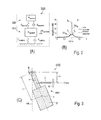
- FIG. 1 a schematic representation of a wind turbine, as an example of a structural installation that, particularly because of its slender structural form, is suitable for attachment of a vibration-absorbing device of a preferred embodiment; in view (A) the wind turbine is shown with a hollow tower, and view (B) shows a particularly notable higher natural-frequency amplitude of a spatial mode on the hollow tower, in particular of a second natural frequency in a region at approximately 2 ⁇ 3 of the height of a wind turbine;
- FIG. 3 a schematic representation of a vibration-absorbing module, as a pendulum system having a pendulum mass and having a laterally engaging spring element;
- FIG. 5 a particularly preferred design of the preferred embodiment of the vibration absorber module of FIG. 4 ;
- FIG. 6 a detail of a pivot head of the pendulum mass suspension of a suspension system in the case of the vibration absorber module of FIG. 4 and FIG. 5 ;
- FIG. 7 a detail of a pendulum spring element of the embodiment of the vibration absorber module of FIG. 4 and FIG. 5 ;
- FIG. 8 a perspective overall view of a particularly preferred embodiment of a vibration-absorbing device having four vibration absorber modules of FIG. 4 and FIG. 5 ;
- FIG. 9 a partially perspective, lateral sectional view of a tower segment for a wind turbine having a vibration-absorbing device of FIG. 8 .
- FIG. 1 in view (A), shows a wind turbine 1000 having a tower 1001 and a nacelle 1002 that is mounted on the tower 1001 .
- the nacelle 1002 carries a rotor 1003 , which has a number of rotor blades 1004 , in this case three.
- a rotor blade 1004 of the rotor 1003 is connected, via a hub 1005 , to a shaft, not represented in greater detail, in the nacelle 1002 .
- a rotor blade 1004 is connected to a hub adapter via a blade bearing, and coupled to the shaft.
- a generator disposed in the nacelle 1002 can be driven, via the shaft, for the purpose of generating electricity.
- the electrical energy supplied by the generator can be converted, by means of electrical power converters, transformers and similar further appropriate electrical devices, for feed-in to an electric grid, not transferred in greater detail; the devices may be disposed in the nacelle 1002 or on the ground 1010 , in the tower 1001 or outside of the tower 1001 of the wind turbine 1000 .
- the tower 1001 of the wind turbine 1000 is let into the ground 1010 via a foundation, not represented in greater detail.
- the tower 1001 of the wind turbine 1000 is constructed from a number of tower segments 1100 —for example, realized as hollow-cylindrical steel or prestressed concrete segments.
- a tower segment 1100 not designated in greater detail here, disposed between the nacelle 1002 and the ground 1010 is equipped with a vibration-absorbing device 200 , which is explained in relation to the subsequent FIGS. 4 to 9 , in a preferred embodiment.
- a wind turbine 1000 does not merely have to satisfy more stringent requirements in respect of damping and/or absorption of unwanted vibration; it was also necessary to specify a design of a vibration-absorbing module 100 , or of a vibration-absorbing device 200 , that is sparing of resources. Since the occurrence of high amplitudes of pronounced resonant phenomena in the case of a wind turbine 1000 was to be prevented as reliably as possible, a vibration absorber module 100 , in particular, has proved advantageous, and it is described here, as an example, in the context of a particularly preferred embodiment.
- vibration absorber module 100 described here, even if initially of a passive design and realized without expressly stated damper means that go beyond self-damping, can nevertheless be further developed as a module—in particular, provided with appropriate active feedback control and/or damping—that reduces vibration in general.
- a wind turbine 1000 can be excited to vibrate, and a spectrum of unwanted vibration, or unwanted vibration phenomena, can be broken down into differing natural vibration modes, each having a spatially distinct mode. Owing to the large number of possible vibration excitations, a spectrum of unwanted vibration, or an unwanted vibration phenomenon, having differing modes in a first and, in particular, in the higher natural frequency beyond the latter, proves to be comparatively complex.
- periodic or other internal and external forces may be superimposed on free and self-excited vibrations of the wind turbine 1000 in order to excite oscillatory motions.
- wind-induced vibrations particularly resulting from gusts or vortex shedding
- Periodic and comparatively high-frequency vibration excitations can also result from two serially positioned wind turbines becoming coupled as a result of vortex shedding, also referred to as buffeting.
- the influencing of wind flows can have the result that wind turbines positioned close to each other are subjected to extensional and bending, or torsional, vibrations, such as, for example, in the case of galloping or fluttering.
- such and other excitations of the rotor blades additionally result in a pitching moment of the nacelle 1002 and in an excitation spectrum of the tower 1001 that includes modes beyond the first natural frequency.
- HA denotes the suspension axis of a vibration-absorbing module 100 , which axis is substantially parallel to a symmetry axis SA of a vibration-absorbing device 200 shown in detail in FIG. 1 and FIG. 8 and FIG. 9 —in which the symmetry axis SA corresponds substantially to the tower axis TA.
- FIG. 1 view (B) shows, as an example, the plotted graph of an amplitude of a higher, in this case second, natural frequency of a mode of the tower 1001 . It is possible, for example, to simulate or measure an exact knowledge of a maximum amplitude of a mode on the tower 1001 ; thus, it is known that it is precisely natural modes above the first natural frequency that occur in a region above half the height of the tower 1001 . It has been found that particularly reliable reduction of such amplitudes can be achieved by a vibration-reducing device having a vibration-reducing module disposed approximately at the height of the greater amplitude of the mode.
- a vibration absorber module 100 or a vibration-absorbing device 200 , as described in FIG. 4 to FIG. 9 .
- This device may be further supplemented, advantageously, by damping or active feedback control elements, in order to achieve a more broadband frequency spectrum of absorption frequencies with an additional vibration damper, or active damping properties.
- vibration absorber module 100 or vibration-damping device 200 .
- a higher natural mode of a tower 1001 , or wind turbine 1000 is in part non-dependent on wind direction, it is nevertheless also useful, where necessary, for the vibration absorption properties to be set, in part, in dependence on wind direction.
- the basis of the present embodiment is a vibration-absorbing module 100 , or vibration-absorbing device 200 that, for the purpose of absorbing vibration, is disposed at a height of approximately 2 ⁇ 3 of the length of the tower 1001 , i.e., approximately at the height of the greatest amplitude of a higher mode; it is disposed thus, for example, in a manner shown in FIG. 8 and FIG. 9 .
- the embodiment of the vibration-absorbing module 100 , or vibration-absorbing device 200 as an initially purely absorbing and passive element, can be designed to be durable—in particular, for the nominal service life of the wind turbine—and used for a very wide temperature range, from ⁇ 40° C. to +60° C.
- the vibration absorber module 100 , or vibration-absorbing device 200 By setting of a so-called “effective pendulum length”—yet without alteration of an actual length of a suspension system and/or alternation of the pendulum mass—the vibration absorber module 100 , or vibration-absorbing device 200 , described in the following can be set to a disturbance frequency in respect of the absorption frequency; it is thus possible to fine-tune the entire vibration-reducing system.
- a natural frequency of 1.48 Hz is to be reduced in a frequency range from 0.4 to 3 Hz.
- FIG. 2 view (A) Shown schematically in FIG. 2 view (A) is a system 2000 —as an example, e.g., for that of a wind turbine 1000 —having a vibration-reducing device 200 coupled to a structure that is capable of vibration—such as, for example, a tower 1001 of a wind turbine 1000 , constituting the coupled system 2000 comprising a device 200 and a wind turbine 1000 —having a system mass msystem of the wind turbine 1000 and an absorber mass M absorber , i.e., substantially a pendulum mass 110 .
- the arrow direction represented by S system denotes the symmetry axis of the tower 1001 of the wind turbine 1000 .
- the oscillatory capability and damping are represented by a spring constant C system and a damping constant d system , and for the absorber by a spring constant C absorber and a damping constant d absorber .
- the spring constants detune the absorber frequencies of the absorber in respect of a disturbance frequency of the system; they thus serve principally to set the absorber frequency, in order to increase the absorbing and, if appropriate, additionally damping effect of the absorber.
- FIG. 2 view (B) shows, for the model in view (A), the resulting amplitude of an unwanted vibration SA 0 , the unwanted vibration having a natural frequency f E , without any vibration-reducing, in particular any vibration-damping, measure.
- SA m represents the progression of a reduced unwanted-vibration amplitude, a dynamic vibration absorber being used, which is of an undamped, passive design.
- the natural frequency f E of the represented mode is split into two frequencies f 1 , f 2 , which are close to each other, lying around the natural frequency f E of the unwanted vibration.
- One advantage is the virtually complete extinction, or in any case great reduction, of the amplitude in the case of f E at least to 2 ⁇ 3 of the original value. It may be necessary to take into account that, outside of the natural frequency f E , comparatively low amplitudes of the frequency split f 1 , f 2 are obtained. For this reason, in particular, it may be useful for the embodiment of a vibration absorber, which is represented further here, to be provided with additional damping, or active feedback control, in order also to reduce the amplitudes of the split frequencies f 1 , f 2 of the coupled system 2000 .
- FIG. 3 Shown schematically in FIG. 3 is the basic functioning of a vibration absorber system 3000 , realized as a pendulum system. It is possible to describe, at a suspension point 0 on the structure B, a pendulum 3001 , which can be described in respect of the center of mass S and has the length l and a pendulum mass m, in the case of a deflection ⁇ in relation to the suspension axis HA, and which has an elastic spring coupling, of a spring constant C, to the structure B.
- a vibration absorber system 3000 realized as a pendulum system. It is possible to describe, at a suspension point 0 on the structure B, a pendulum 3001 , which can be described in respect of the center of mass S and has the length l and a pendulum mass m, in the case of a deflection ⁇ in relation to the suspension axis HA, and which has an elastic spring coupling, of a spring constant C, to the structure B.
- a motion equation for the vibration absorber system 3000 also includes, in addition to the pendulum length l and the pendulum mass m, the spring constant C and a distance a in relation to the suspension point 0; this is described, for example, by Petersen in “Dynamik der Baukonstrutation” (Vieweg 2000, first edition, Kunststoff).
- a pendulum mass which is represented as a spring
- the spring constant C in this case detunes the natural frequency of the pendulum, i.e., in this case it serves primarily to set the absorber frequency, in order to increase the absorbing and, if appropriate, additionally damping effect of the device 200 .
- FIG. 4 view (A) is a particularly preferred embodiment of a vibration absorber module 100 for a vibration-absorbing device 200 , described further in FIG. 8 , for use in the case of a wind turbine 1000 represented in FIG. 1 and FIG. 9 .
- the vibration absorber module 100 is designed for suspended attachment to the vibration-absorbing device 200 and, via the latter, to the tower segment 1100 of the wind turbine 1000 .
- the vibration absorber module 100 has a pendulum system 101 , having a pendulum mass 110 and having a suspension system 120 for suspending the pendulum mass 110 on a bearing structure 150 .
- the suspension system 120 in addition to having a pendulum mass suspension 130 , which is fastened to the structure 150 by means of a suspension head 170 , also has a number of pendulum spring elements 140 that extend, between the pendulum mass 110 and the bearing structure 150 , in the direction of a suspension axis HA of the vibration absorber module 100 ; the suspension axis HA corresponds substantially to a tower axis TA shown in FIG. 1 .
- the suspension system 120 is shown for a center of mass S of the pendulum mass 110 that is deflected, relative to the suspension axis HA, by the deflection ⁇ .
- the spring axes FA of the pendulum spring elements 140 that are shown here, and also the axis PA of the pendulum mass suspension 130 are substantially parallel to the suspension axis HA and, in the deflected state, are deflected relative to the suspension axis HA.
- FIG. 4 view (B) shows, furthermore, that eight pendulum spring elements 140 are distributed symmetrically around the suspension axis HA; in the case of the embodiment of a vibration absorber module 100 that is represented symbolically in this case, these pendulum spring elements are thus aligned vertically, i.e., with their spring axis FA parallel to the suspension axis HA when they are in the non-deflected state and, when in the deflected state, carried along substantially parallel to the pendulum axis PA of the pendulum mass suspension 130 .
- the spring elements 140 are preferably designed for setting the vibration absorber module 100 .
- a vibration absorber module 100 that can be used in real conditions should, in principle, be configured such that it can be set, in order to design an absorber frequency f in respect of a frequency spectrum F of an unwanted vibration, in particular in order to tune the absorber frequency f to a natural frequency f E .
- This tuning requirement may arise, for example, as a result of production tolerances, such as geometry deviations, mass deviations and deviating spring rates, in the case of a wind turbine 1000 , even if a disturbance frequency spectrum can be calculated on the basis of the structural design.
- the vibration absorber module 100 represented in detail in FIG. 5 provides for the possibility of setting the pendulum spring elements 140 ; this has the advantage of avoiding elaborate alteration of the length of the pendulum mass suspension 130 . This also has the advantage that the pendulum mass suspension 130 can be specifically designed to achieve a durable, maintenance-free and yet simple design of the suspension system 120 .
- altering a pretension of a pendulum spring element 130 in particular by altering a pretension length of a spring 141 , designed as a compression spring, of a pendulum spring element 140 , is effective in achieving an effect similar to that achieved by increasing the pendulum mass or altering the pendulum length.
- this situation is described with reference to an effective alteration of the pendulum length—meaning an effective—but not spatial—extension or alteration of a pendulum length l, merely through the design of a spring pretension of a pendulum spring element 140 , in particular by using the spring length of the spring 141 to set a compressive spring force of the compression spring of the pendulum spring element 140 .
- the pendulum mounting is supplemented with compression springs of a number of pendulum spring elements 140 ; by means of a bearing structure plate 151 , the pressure is applied, in the present case, on eight compression springs.
- the pendulum spring elements 140 are uniformly distributed along a circumferential course.
- a setting means, for setting a spring length for a pendulum spring element 130 is realized in such a manner that a rotary motion that determines adjustment can be converted into a translational motion that sets pressure.
- pendulum spring elements 140 distributed on a circular circumference allows the pendulum mass 110 to spring against the bearing structure plate 151 in a largely uniform manner in all directions of motion; this is achieved with a technically acceptable resource requirement. It is generally the case, moreover, that a greater number of pendulum spring elements 140 would reduce a directional dependence of the pendulum characteristics. In the present case, it proves to be particularly advantageous that the pendulum spring elements 140 are attached to a supporting structure 150 at virtually the same height as a pendulum mass suspension 110 , namely, in that there is an attachment point on the same plane of the bearing structure plate 151 .
- FIG. 5 shows in detail a vibration absorber module 100 with the pendulum system 101 on a bearing structure 150 .
- the bearing structure 150 has a bearing structure plate 151 , attached to the underside of which—in the vertical direction, i.e., suspended along the suspension axis HA—is the pendulum system 101 with the suspension system 120 for suspended attachment of the pendulum mass 110 .
- the bearing structure plate 151 itself is held, on its top side, by a profile carrier 201 of the vibration-absorbing device 200 .
- the profile carrier 201 may be fixed, for example, to a tower segment 1100 of the tower 1001 of the wind turbine 1000 .
- the profile carrier 201 is held by means of a tensioning and clamping device 210 .
- the tensioning and clamping device 210 can be varied in length.
- the tensioning and clamping device 210 has a joint 211 , to which a fastening profile 212 is attached in a manner permitting angular adjustment and fitted into the receiving region of the profile carrier 201 .
- Extending through both sides of the fastening profile 212 and the carrier profile 201 is a carrying screw 213 , which sits against the outside of the carrier profile 201 on both sides, in particular, in the present case, fastened by a nut.
- the bearing structure plate 151 on its underside, on the one hand provides at the same height a flat stop surface for a joint head 131 on a suspension head 170 of the pendulum mass suspension 130 ; the joint head 131 has a pendulum bearing 160 , realized as a slide bearing, that is realized between a bearing pin 161 and a bearing pin receiver 162 .
- FIG. 6 shows the suspension head 170 in detail, and shows the design of the joint head 160 , with a carrier plate 172 of the bearing pin receiver 162 and an inner ring 171 on the bearing pin 161 .
- the carrier plate 172 of the bearing pin receiver 162 is fixed to the bearing structure plate 151 by screwed connections 152 that sit against an underside of the carrier plate 172 and a top side of the bearing structure plate 151 .
- the carrier profile 201 can be fixed, at its abutting edge, to the bearing structure plate 151 , for example by welding or else by material bonding, form closure or force closure.
- the bearing pin receiver 162 additionally has a first and a second side plate 174 . 1 , 174 . 2 , disposed perpendicularly in relation to the carrier plate 172 .
- Each of the side plates 174 . 1 , 174 . 2 has a bearing bore 176 . 1 , 176 . 2 , which are realized to receive the bearing pin 161 , preferably in a precisely fitting manner, along the bearing axis LA.
- the bearing pin 161 itself is fixed, on an outside of a second side plate 174 . 2 , by means of a stop 163 of the bearing pin 161 .
- the bearing pin 161 is fixed by a locknut on a first outer side of a first side plate 174 .
- a first and a second locknut 162 . 1 , 162 . 2 on the external thread 165 are spaced apart from the first outer side of the first outer side plate 174 . 1 by means of a washer 164 and, by means of a split pin 166 at the end of the bearing pin 161 , are additionally secured against slackening.
- the nuts 162 . 1 , 162 . 2 are each preferably realized as hexagon nuts. Between the side plates 174 . 1 , 174 . 2 , an inner ring 171 of the bearing pin is held centrally spaced between the side plates 174 . 1 , 174 . 2 by a spacer bush 168 .
- a slide surface constituting a slide bearing, is realized on an inside of the inner ring 171 that faces towards the bearing pin.
- the inner ring 171 On its outer sides that face towards the side plates 174 . 1 , 174 . 2 , the inner ring 171 is additionally sealed on both sides by a lip seal 169 .
- the lip seals 169 are composed of polyurethane, and thus have good cold-state elasticity and low restoring forces.
- the inner ring 171 with its slide surface lying in a precisely fitting manner on the bearing pin 161 , together with the opposing slide surface of the bearing pin 161 that faces towards the slide surface of the inner ring, constitutes the slide bearing.
- the slide surfaces of the slide bearing are composed of roller-bearing steel. All components of the joint head 131 , as well as the bearing pin 161 and the bearing pin receiver 162 , are provided with a zinc coating that protects against corrosion. Additionally or alternatively, particularly if required, the joint head 131 may also be provided with a Teflon slide coating in the region of the slide layer. This reduces the frictional resistance and ensures the durability of the slide bearing.
- the joint head 131 continues, integrally or in a form-closed manner, into a pendulum rod 133 of the pendulum mass suspension 130 .
- the pendulum rod 133 extends centrally through the pendulum mass 110 and, at its lower end 132 , carries a set of locknuts 133 . 1 , 133 . 2 on a washer 133 . 3 , which are secured against slackening.
- an extension piece 135 that, as an extension, appropriately continues the inner ring 171 and that directly adjoins the pendulum rod 133 .
- a further locknut 134 sits on the pendulum rod and fixes a pressure plate 111 in position above the pendulum mass 110 .
- the pendulum mass 110 is fixed between the pressure plate 111 and the washer 133 . 3 , this fixing corresponding to the torque of the locknuts 134 , 133 . 1 , 133 . 2 .
- FIG. 5 and FIG. 7 show a number of pendulum spring elements 140 in the direction of the suspension axis HA between the pendulum mass 110 and the supporting structure 150 , namely, and specifically, between a top side of the pendulum mass 110 and an underside of the supporting structure plate 151 .
- the parts are represented in detail in FIG. 7 , a pendulum spring element 140 having, in respect of the bearing structure plate 151 , a spring 141 designed as a compression spring.
- the pendulum spring element 140 also has a setting mechanism 180 , of which a first part 180 . 1 is located above the bearing structure plate 151 and a second part 180 . 2 is located beneath the bearing structure plate 151 .
- the setting mechanism 180 additionally has a third part 180 . 3 , which is located on a guide rod and which, specifically, is realized to displace the second part 180 . 2 against the first part 180 . 1 .
- a spring disc 181 is provided, beneath the bearing structure plate 151 and spaced apart from the latter, as a base for the second part 180 . 2 .
- the spring disc 181 holds the spring 141 , realized as a compression spring, under compressive stress under the spring disc 181 , such that this spring is pretensioned through shortening of its spring length.
- a distance ED for setting the spring length a can be set by means of the aforementioned third part 180 . 3 of the setting mechanism 180 .
- a carrier profile 182 by constituting a first part 180 . 1 of the setting mechanism 180 above the bearing structure plate 151 , holds the variably settable adjuster 183 , as a third part 180 . 3 of the setting mechanism.
- the adjuster 183 is part of a spring pretensioning system, which is supported against the first part 180 . 1 in the form of the carrier profile 182 , and which, by means of the first part 180 . 1 , imparts a compressive pretension to the spring disc 181 , and thereby to the spring 141 .
- the third part 180 . 3 comprising the adjuster 183 works by converting rotary motion into a translational motion.
- the adjuster 183 is realized substantially as a motion screw.
- the motion screw of the adjuster 183 is provided with a region that has an angular shape, namely, a square profile 190 Q.
- the guide rod 190 is guided in the region of the square profile 190 Q.
- circular polymer bushes having a square hole are provided, and bonded-in by means of a two-component industrial adhesive.
- a square hole can be made in the bearing structure plate 151 , e.g., by milling, by means of a milling cutter.
- the motion screw of the adjuster 183 has a guide rod 190 , having the portionally square profile 190 Q in the middle portion, which profile sits in the carrier profile 182 that, in the present case, is in the shape of an inverted U-profile.
- the square profile 190 Q is flanked on both sides by a first and a second hexagon nut, as counter-screws 191 . 1 , 191 . 2 having associated washers 191 . 1 U, 191 . 2 U.
- the guide rod 190 extends through a guide bush 193 seated in the bearing structure plate 151 —namely, let into an opening 153 of the latter.
- the guide rod 190 also extends through the spring disc 181 ; it extends thus without a guide bush between a widened cylinder profile 190 Z of the guide rod 190 and a threaded extension 190 G of the guide rod 190 .
- the guide rod 190 may also have a narrow cross section, and thus extend through a bush or similar sleeve in order to form the cylindrical outer profile of the cylinder profile 190 Z.
- the guide rod 190 carries this threaded extension 190 G, which is encompassed by a washer and two locknuts 192 . 1 , 192 . 2 —one realized as a hexagon nut, the other as a cap nut.
- FIG. 8 shows a preferred embodiment of a vibration-absorbing device 200 having, in the present case, four vibration absorber modules 100 . 1 , 100 . 2 , 100 . 3 , 100 . 4 .
- the profile carrier 201 shown in FIG. 5 here, as the profile carrier 201 . 1 and the profile carrier 201 . 2 —is fixed laterally, by flanges or similar attachment structures 230 , in a tower segment 1100 .
- a first, shorter web 230 . 1 having a first bent-over end flange 231 . 1
- a second, longer web 230 . 2 having a second bent-over end flange 231 .
- two vibration absorber modules 100 . 1 , 100 . 2 , and 100 . 3 , 100 . 4 are in each case fixed in pairs to a carrier profile 201 . 1 and 201 . 2 , respectively, of a bearing structure 150 .
- a tensioning structure 220 which can be tensioned in a settable manner and which serves as an anti-drop safeguard; in the present case, as an example, it connects the pendulum mass 110 to a carrier profile 201 . 1 and 201 . 2 , respectively.
- a vibration-absorbing module 100 can be installed in the tower segment 1100 in such a manner that it is easily accessible and consequently, most importantly, requires no maintenance and is resistant to wear. Stop buffers may be provided on a vibration absorber module 100 , or in the vibration-absorbing device 200 , in order to limit spatially a maximum swing of a module and thus protect the tower segment 1100 against damage. As represented in detail in FIG. 9 , a vibration-absorbing device 200 may be accessed via a landing 300 . A platform 310 of the landing 300 is disposed above the platform constituted by the carrier profile 201 . 1 , or 201 . 2 .
- the landing 300 has a support guard rail 320 around a free space along the tower axis TA, via which it is possible to access the vibration-absorbing device 200 ; the support guard rail 320 may be removed or bypassed for this purpose.
- a spring length for a pendulum spring element 130 can thus be set, not only with the use of a standardized tool, but also comparatively easily. Moreover, a spring length can be set in a manner that permits calibration and measurement; altogether, the vibration-absorbing device 200 can be set in a simple and determinable manner, with comparatively little resource requirement.
Applications Claiming Priority (4)
| Application Number | Priority Date | Filing Date | Title |
|---|---|---|---|
| DE102012222191.3A DE102012222191A1 (de) | 2012-12-04 | 2012-12-04 | Schwingungsbegrenzungs-Modul sowie Vorrichtung, Bausegment für eine Baueinrichtung und Windenergieanlage mit einem Schwingungsbegrenzungs-Modul |
| DE102012222191.3 | 2012-12-04 | ||
| DE102012222191 | 2012-12-04 | ||
| PCT/EP2013/075151 WO2014086686A1 (de) | 2012-12-04 | 2013-11-29 | Schwingungsbegrenzungs-modul sowie vorrichtung, bausegment für eine baueinrichtung und windenergieanlage mit einem schwingungsbegrenzungs-modul |
Publications (2)
| Publication Number | Publication Date |
|---|---|
| US20150322923A1 US20150322923A1 (en) | 2015-11-12 |
| US10024378B2 true US10024378B2 (en) | 2018-07-17 |
Family
ID=49709660
Family Applications (1)
| Application Number | Title | Priority Date | Filing Date |
|---|---|---|---|
| US14/649,118 Expired - Fee Related US10024378B2 (en) | 2012-12-04 | 2013-11-29 | Vibration-limiting module and device, structural segment for a structural installation, and wind turbine having a vibration-limiting module |
Country Status (20)
| Country | Link |
|---|---|
| US (1) | US10024378B2 (es) |
| EP (1) | EP2929098B1 (es) |
| JP (1) | JP2016505778A (es) |
| KR (1) | KR101756566B1 (es) |
| CN (1) | CN104838075B (es) |
| AR (1) | AR093724A1 (es) |
| AU (1) | AU2013354259B2 (es) |
| BR (1) | BR112015013038A8 (es) |
| CA (1) | CA2892978A1 (es) |
| CL (1) | CL2015001466A1 (es) |
| DE (1) | DE102012222191A1 (es) |
| DK (1) | DK2929098T3 (es) |
| ES (1) | ES2748801T3 (es) |
| MX (1) | MX2015006975A (es) |
| NZ (1) | NZ708905A (es) |
| PT (1) | PT2929098T (es) |
| RU (1) | RU2621427C2 (es) |
| TW (1) | TWI541415B (es) |
| WO (1) | WO2014086686A1 (es) |
| ZA (1) | ZA201503764B (es) |
Cited By (5)
| Publication number | Priority date | Publication date | Assignee | Title |
|---|---|---|---|---|
| US10184245B2 (en) * | 2016-06-16 | 2019-01-22 | Chunil Co., Ltd. | Earthquake-resistant light tower with the tuned mass damper |
| CN111425554A (zh) * | 2020-04-15 | 2020-07-17 | 钟少玲 | 一种风能发电设备安装装置 |
| US20210190039A1 (en) * | 2018-08-03 | 2021-06-24 | Siemens Gamesa Renewable Energy Innovation & Technology S.L. | Wind turbine tower system for second natural frequency modification |
| US11255395B2 (en) * | 2016-11-29 | 2022-02-22 | Burkhard Dahl | Compact spatial ellipsoidal mass pendulum |
| US11815150B1 (en) | 2022-12-21 | 2023-11-14 | Powerchina Sepco1 Electric Power Construction Co., Ltd. | Magnetostriction-based vibration suppression apparatus for steel pipe of power transmission tower and suppression method thereof |
Families Citing this family (26)
| Publication number | Priority date | Publication date | Assignee | Title |
|---|---|---|---|---|
| US9556851B2 (en) * | 2013-04-03 | 2017-01-31 | General Electric Company | System for reducing vibration in a wind turbine |
| DE102014013636B4 (de) * | 2014-09-19 | 2017-01-26 | Uwe Starossek | Pendelmechanismus zur Schwingungskontrolle einer Konstruktion |
| KR20170091679A (ko) | 2014-12-05 | 2017-08-09 | 이에스엠 에네르기-운트 쉬빙웅스테크니크 미츠시 게엠베하 | 수직 스프링 메커니즘을 갖는 감응식 진동 댐퍼 |
| CN105604185B (zh) * | 2016-01-21 | 2017-12-19 | 倪黄女 | 一种抗震建筑支架连接结构及其连接方法 |
| CN109312715B (zh) * | 2016-04-08 | 2020-09-01 | 维斯塔斯风力系统集团公司 | 包括多轴加速度计的风力涡轮机的控制 |
| EP3269997B1 (en) * | 2016-07-14 | 2020-01-01 | Siemens Gamesa Renewable Energy A/S | Oscillation absorber for a structure |
| CN106846852B (zh) * | 2016-12-23 | 2023-04-07 | 长沙理工大学 | 一种基于风压的自供电交通灯系统 |
| DE102017107912A1 (de) | 2017-04-12 | 2018-10-18 | Wobben Properties Gmbh | Schwingungsdämpfung eines Windenergieanlagenturms |
| CN107268821B (zh) * | 2017-06-16 | 2023-06-02 | 山东大学 | 一种多级混合型耗能减振装置 |
| DE102017124412A1 (de) * | 2017-10-19 | 2019-04-25 | Innogy Se | Soft-Soft Gründung für Offshore-Bauwerke |
| JP7093203B2 (ja) | 2018-03-07 | 2022-06-29 | 五洋建設株式会社 | 塔型構造物及びその構造最適化方法 |
| US11078890B2 (en) * | 2018-05-22 | 2021-08-03 | Engiso Aps | Oscillating damper for damping tower harmonics |
| WO2020126070A1 (de) * | 2018-12-21 | 2020-06-25 | Esm Energie- Und Schwingungstechnik Mitsch Gmbh | Impuls-schwingungstilger für hohe schlanke strukturen |
| CN109610673B (zh) * | 2019-02-01 | 2023-11-24 | 青岛理工大学 | 主动转动惯量驱动控制系统 |
| EP4107407A1 (de) * | 2020-02-17 | 2022-12-28 | FM Energie GmbH & Co. KG | Adaptiver schwingungstilger zur dämpfung niedriger erregerfrequenzen |
| CN111502921B (zh) * | 2020-04-24 | 2021-05-18 | 浙江运达风电股份有限公司 | 一种风力发电机组柔性塔筒用的全向调谐质量阻尼器 |
| CN113775902B (zh) * | 2020-06-10 | 2023-08-22 | 北京金风科创风电设备有限公司 | 阻尼器支撑装置、阻尼系统、塔筒及塔筒的组装方法 |
| CN112227181B (zh) * | 2020-10-20 | 2022-06-14 | 精易建工集团有限公司 | 一种用于桥梁的减震结构及其使用方法 |
| CN112648138B (zh) * | 2020-12-25 | 2022-09-13 | 贝克曼沃玛金属技术(青岛)有限公司 | 一种立轴风力发电设备 |
| CN113062649B (zh) * | 2021-03-31 | 2022-01-18 | 重庆大学 | 一种基于参数设计计算的预应力调谐质量阻尼器安装方法 |
| CN113218199B (zh) * | 2021-05-28 | 2023-09-15 | 包头华鼎铜业发展有限公司 | 一种底吹熔炼炉加料口粘接物清理装置 |
| CN113235776B (zh) * | 2021-06-02 | 2022-03-08 | 同济大学 | 一种可恢复功能装配式抗震剪力墙结构 |
| CN113789879B (zh) * | 2021-09-07 | 2022-09-16 | 湖南省潇振工程科技有限公司 | 一种滑轮式调谐质量电涡流阻尼器 |
| CN114017260B (zh) * | 2021-10-27 | 2023-06-23 | 华能沂水风力发电有限公司 | 一种用于风力发电机套筒支撑架的主动式防共振装置 |
| CN114876996B (zh) * | 2022-04-14 | 2024-03-26 | 浙江飞碟汽车制造有限公司 | 用于商用车减振的钟摆式动力吸振器及其设计方法 |
| CN115111345B (zh) * | 2022-08-22 | 2023-01-24 | 太原科技大学 | 一种径向/推力滑动轴承组合支承结构的风电增速齿轮箱 |
Citations (25)
| Publication number | Priority date | Publication date | Assignee | Title |
|---|---|---|---|---|
| US3483951A (en) * | 1968-12-06 | 1969-12-16 | Wisconsin Alumni Res Found | Self-optimizing vibration dampers |
| GB2040429A (en) | 1979-01-17 | 1980-08-28 | Nat Res Dev | Improvements in or relating to stabilising structures against oscillation |
| SU1208371A2 (ru) | 1984-07-13 | 1986-01-30 | Центральный Ордена Трудового Красного Знамени Научно-Исследовательский Институт Строительных Конструкций Им.В.А.Кучеренко | Гаситель колебаний ма тникового типа |
| SU1307078A1 (ru) | 1985-12-11 | 1987-04-30 | В,А,Викторук | Ветроэлектрический агрегат |
| JPS6353330A (ja) | 1986-08-20 | 1988-03-07 | Nippon Kokan Kk <Nkk> | 上下振子式動吸振器 |
| JPH03213741A (ja) | 1990-01-16 | 1991-09-19 | Mitsubishi Heavy Ind Ltd | 自動追従型動吸振装置 |
| KR930013510A (ko) | 1991-12-20 | 1993-07-22 | 카르스텐센, 브레이크 | 강철재 레이디얼 롤링 베어링 |
| JPH05187481A (ja) | 1992-01-13 | 1993-07-27 | Mitsubishi Heavy Ind Ltd | 振り子式制振装置 |
| JPH0643350U (ja) | 1992-11-18 | 1994-06-07 | 光洋精工株式会社 | 電食防止転がり軸受 |
| JPH0712123A (ja) | 1993-06-25 | 1995-01-17 | Nippon Seiko Kk | シール付すべり軸受 |
| US5543236A (en) * | 1993-12-27 | 1996-08-06 | Daido Metal Company, Ltd. | Multi-layered slide bearing material |
| DE19734993A1 (de) | 1997-08-13 | 1999-03-11 | Friedhelm Bierwirth | Erdbebensicherung durch schwingungsentkoppelte Lagerung von Gebäuden und Objekten über virtuelle Pendel mit langer Periodendauer |
| EP1008747A2 (de) * | 1998-12-08 | 2000-06-14 | Franz Mitsch | Schwingungstilger für Windkraftanlagen |
| JP2003239947A (ja) | 2002-02-20 | 2003-08-27 | Takenaka Komuten Co Ltd | 制振装置用軸受 |
| US6672763B1 (en) | 1998-11-05 | 2004-01-06 | Ina-Schaeffler Kg | Compensating bearing |
| EP1479938A1 (en) | 2002-02-27 | 2004-11-24 | Ishikawajima-Harima Heavy Industries Co., Ltd. | Damping device and method for setting natural frequency of damping body in the damping device |
| DE202005019949U1 (de) | 2005-12-21 | 2006-03-09 | Eras Entwicklung Und Realisation Adaptiver Systeme Gmbh | Schwingungstilger mit variabler Tilgereigenfrequenz |
| JP2008157296A (ja) | 2006-12-21 | 2008-07-10 | Kurashiki Kako Co Ltd | 動吸振器 |
| JP2009228726A (ja) | 2008-03-21 | 2009-10-08 | Daido Metal Co Ltd | すべり軸受 |
| DE102008050989A1 (de) | 2008-10-13 | 2010-04-15 | Isoloc Schwingungstechnik Gmbh | Gedämpfte Tilger zur Reduzierung der Schwingungen der rotierenden Maschinenteile |
| CN101852188A (zh) | 2010-06-17 | 2010-10-06 | 唐德尧 | 一种风力发电机塔架减振装置及设计方法 |
| KR20110010605A (ko) | 2008-05-08 | 2011-02-01 | 섀플러 테크놀로지스 게엠베하 운트 코. 카게 | 베어링 모듈 |
| JP2011025346A (ja) | 2009-07-24 | 2011-02-10 | Sanyo Special Steel Co Ltd | 摺動性と表面圧縮残留応力を同時に付与するショットピーニング用粉末およびそれを用いた摺動性部材の製造方法 |
| US20120063915A1 (en) * | 2010-12-27 | 2012-03-15 | Mitsubishi Heavy Industries, Ltd. | Vibration control apparatus of wind turbine generator and wind turbine generator |
| JP2012122546A (ja) | 2010-12-08 | 2012-06-28 | Mitsubishi Heavy Ind Ltd | 風力発電用風車の制振装置 |
Family Cites Families (2)
| Publication number | Priority date | Publication date | Assignee | Title |
|---|---|---|---|---|
| JPH0750405Y2 (ja) * | 1990-03-19 | 1995-11-15 | 三菱重工業株式会社 | 標識柱用動吸振器 |
| JP3923888B2 (ja) * | 2002-12-11 | 2007-06-06 | 株式会社東芝 | ポール構造物 |
-
2012
- 2012-12-04 DE DE102012222191.3A patent/DE102012222191A1/de not_active Withdrawn
-
2013
- 2013-11-29 RU RU2015126790A patent/RU2621427C2/ru not_active IP Right Cessation
- 2013-11-29 CN CN201380063500.3A patent/CN104838075B/zh not_active Expired - Fee Related
- 2013-11-29 US US14/649,118 patent/US10024378B2/en not_active Expired - Fee Related
- 2013-11-29 KR KR1020157017970A patent/KR101756566B1/ko active IP Right Grant
- 2013-11-29 BR BR112015013038A patent/BR112015013038A8/pt not_active Application Discontinuation
- 2013-11-29 ES ES13799280T patent/ES2748801T3/es active Active
- 2013-11-29 NZ NZ708905A patent/NZ708905A/en not_active IP Right Cessation
- 2013-11-29 AU AU2013354259A patent/AU2013354259B2/en not_active Ceased
- 2013-11-29 DK DK13799280T patent/DK2929098T3/da active
- 2013-11-29 MX MX2015006975A patent/MX2015006975A/es unknown
- 2013-11-29 PT PT137992806T patent/PT2929098T/pt unknown
- 2013-11-29 CA CA2892978A patent/CA2892978A1/en not_active Abandoned
- 2013-11-29 EP EP13799280.6A patent/EP2929098B1/de active Active
- 2013-11-29 WO PCT/EP2013/075151 patent/WO2014086686A1/de active Application Filing
- 2013-11-29 JP JP2015545752A patent/JP2016505778A/ja active Pending
- 2013-12-03 TW TW102144247A patent/TWI541415B/zh not_active IP Right Cessation
- 2013-12-04 AR ARP130104478A patent/AR093724A1/es active IP Right Grant
-
2015
- 2015-05-27 ZA ZA2015/03764A patent/ZA201503764B/en unknown
- 2015-05-29 CL CL2015001466A patent/CL2015001466A1/es unknown
Patent Citations (33)
| Publication number | Priority date | Publication date | Assignee | Title |
|---|---|---|---|---|
| US3483951A (en) * | 1968-12-06 | 1969-12-16 | Wisconsin Alumni Res Found | Self-optimizing vibration dampers |
| GB2040429A (en) | 1979-01-17 | 1980-08-28 | Nat Res Dev | Improvements in or relating to stabilising structures against oscillation |
| SU1208371A2 (ru) | 1984-07-13 | 1986-01-30 | Центральный Ордена Трудового Красного Знамени Научно-Исследовательский Институт Строительных Конструкций Им.В.А.Кучеренко | Гаситель колебаний ма тникового типа |
| SU1307078A1 (ru) | 1985-12-11 | 1987-04-30 | В,А,Викторук | Ветроэлектрический агрегат |
| JPS6353330A (ja) | 1986-08-20 | 1988-03-07 | Nippon Kokan Kk <Nkk> | 上下振子式動吸振器 |
| JPH03213741A (ja) | 1990-01-16 | 1991-09-19 | Mitsubishi Heavy Ind Ltd | 自動追従型動吸振装置 |
| KR930013510A (ko) | 1991-12-20 | 1993-07-22 | 카르스텐센, 브레이크 | 강철재 레이디얼 롤링 베어링 |
| JPH05187481A (ja) | 1992-01-13 | 1993-07-27 | Mitsubishi Heavy Ind Ltd | 振り子式制振装置 |
| JPH0643350U (ja) | 1992-11-18 | 1994-06-07 | 光洋精工株式会社 | 電食防止転がり軸受 |
| JPH0712123A (ja) | 1993-06-25 | 1995-01-17 | Nippon Seiko Kk | シール付すべり軸受 |
| US5543236A (en) * | 1993-12-27 | 1996-08-06 | Daido Metal Company, Ltd. | Multi-layered slide bearing material |
| US6966154B1 (en) | 1997-08-13 | 2005-11-22 | Plandesign International Llc | Earthquake protection consisting of vibration-isolated mounting of buildings and objects using virtual pendulums with long cycles |
| DE19734993A1 (de) | 1997-08-13 | 1999-03-11 | Friedhelm Bierwirth | Erdbebensicherung durch schwingungsentkoppelte Lagerung von Gebäuden und Objekten über virtuelle Pendel mit langer Periodendauer |
| US6672763B1 (en) | 1998-11-05 | 2004-01-06 | Ina-Schaeffler Kg | Compensating bearing |
| EP1008747A2 (de) * | 1998-12-08 | 2000-06-14 | Franz Mitsch | Schwingungstilger für Windkraftanlagen |
| EP1008747B1 (de) | 1998-12-08 | 2008-06-04 | Franz Mitsch | Schwingungstilger für Windkraftanlagen |
| JP2003239947A (ja) | 2002-02-20 | 2003-08-27 | Takenaka Komuten Co Ltd | 制振装置用軸受 |
| US7707787B2 (en) * | 2002-02-27 | 2010-05-04 | Ishikawajima-Harima Heavy Industries Co., Ltd. | Damping device and method for setting natural frequency of damping body in the damping device |
| EP1479938A1 (en) | 2002-02-27 | 2004-11-24 | Ishikawajima-Harima Heavy Industries Co., Ltd. | Damping device and method for setting natural frequency of damping body in the damping device |
| DE202005019949U1 (de) | 2005-12-21 | 2006-03-09 | Eras Entwicklung Und Realisation Adaptiver Systeme Gmbh | Schwingungstilger mit variabler Tilgereigenfrequenz |
| JP2008157296A (ja) | 2006-12-21 | 2008-07-10 | Kurashiki Kako Co Ltd | 動吸振器 |
| US8235596B2 (en) | 2008-03-21 | 2012-08-07 | Daido Metal Company Ltd. | Sliding bearing |
| JP2009228726A (ja) | 2008-03-21 | 2009-10-08 | Daido Metal Co Ltd | すべり軸受 |
| KR20110010605A (ko) | 2008-05-08 | 2011-02-01 | 섀플러 테크놀로지스 게엠베하 운트 코. 카게 | 베어링 모듈 |
| DE102008050989A1 (de) | 2008-10-13 | 2010-04-15 | Isoloc Schwingungstechnik Gmbh | Gedämpfte Tilger zur Reduzierung der Schwingungen der rotierenden Maschinenteile |
| JP2011025346A (ja) | 2009-07-24 | 2011-02-10 | Sanyo Special Steel Co Ltd | 摺動性と表面圧縮残留応力を同時に付与するショットピーニング用粉末およびそれを用いた摺動性部材の製造方法 |
| CN101852188A (zh) | 2010-06-17 | 2010-10-06 | 唐德尧 | 一种风力发电机塔架减振装置及设计方法 |
| JP2012122546A (ja) | 2010-12-08 | 2012-06-28 | Mitsubishi Heavy Ind Ltd | 風力発電用風車の制振装置 |
| WO2012090259A1 (ja) | 2010-12-27 | 2012-07-05 | 三菱重工業株式会社 | 風力発電用風車の制振装置および風力発電用風車 |
| US20120063915A1 (en) * | 2010-12-27 | 2012-03-15 | Mitsubishi Heavy Industries, Ltd. | Vibration control apparatus of wind turbine generator and wind turbine generator |
| CN102713278A (zh) | 2010-12-27 | 2012-10-03 | 三菱重工业株式会社 | 风力发电用风车的减震装置及风力发电用风车 |
| KR20120111911A (ko) | 2010-12-27 | 2012-10-11 | 미츠비시 쥬고교 가부시키가이샤 | 풍력 발전용 풍차의 제진 장치 및 풍력 발전용 풍차 |
| US8322975B2 (en) * | 2010-12-27 | 2012-12-04 | Mitsubishi Heavy Industries, Ltd. | Vibration control apparatus of wind turbine generator and wind turbine generator |
Non-Patent Citations (1)
| Title |
|---|
| AST Bearings LLC (Bearing Materials 2010). * |
Cited By (6)
| Publication number | Priority date | Publication date | Assignee | Title |
|---|---|---|---|---|
| US10184245B2 (en) * | 2016-06-16 | 2019-01-22 | Chunil Co., Ltd. | Earthquake-resistant light tower with the tuned mass damper |
| US11255395B2 (en) * | 2016-11-29 | 2022-02-22 | Burkhard Dahl | Compact spatial ellipsoidal mass pendulum |
| US20210190039A1 (en) * | 2018-08-03 | 2021-06-24 | Siemens Gamesa Renewable Energy Innovation & Technology S.L. | Wind turbine tower system for second natural frequency modification |
| CN111425554A (zh) * | 2020-04-15 | 2020-07-17 | 钟少玲 | 一种风能发电设备安装装置 |
| CN111425554B (zh) * | 2020-04-15 | 2021-01-22 | 广发惠东风电有限公司 | 一种风能发电设备安装装置 |
| US11815150B1 (en) | 2022-12-21 | 2023-11-14 | Powerchina Sepco1 Electric Power Construction Co., Ltd. | Magnetostriction-based vibration suppression apparatus for steel pipe of power transmission tower and suppression method thereof |
Also Published As
| Publication number | Publication date |
|---|---|
| DK2929098T3 (da) | 2019-11-18 |
| JP2016505778A (ja) | 2016-02-25 |
| ZA201503764B (en) | 2016-02-24 |
| EP2929098A1 (de) | 2015-10-14 |
| WO2014086686A1 (de) | 2014-06-12 |
| KR101756566B1 (ko) | 2017-07-26 |
| CN104838075A (zh) | 2015-08-12 |
| BR112015013038A2 (pt) | 2017-07-11 |
| ES2748801T3 (es) | 2020-03-18 |
| RU2621427C2 (ru) | 2017-06-06 |
| TWI541415B (zh) | 2016-07-11 |
| AU2013354259B2 (en) | 2017-02-02 |
| MX2015006975A (es) | 2015-09-28 |
| RU2015126790A (ru) | 2017-01-12 |
| US20150322923A1 (en) | 2015-11-12 |
| TW201443322A (zh) | 2014-11-16 |
| AR093724A1 (es) | 2015-06-17 |
| PT2929098T (pt) | 2019-11-27 |
| CA2892978A1 (en) | 2014-06-12 |
| DE102012222191A1 (de) | 2014-06-05 |
| AU2013354259A1 (en) | 2014-06-12 |
| CN104838075B (zh) | 2017-09-15 |
| CL2015001466A1 (es) | 2015-10-02 |
| NZ708905A (en) | 2016-05-27 |
| BR112015013038A8 (pt) | 2019-10-08 |
| EP2929098B1 (de) | 2019-08-21 |
| KR20150091408A (ko) | 2015-08-10 |
Similar Documents
| Publication | Publication Date | Title |
|---|---|---|
| US10024378B2 (en) | Vibration-limiting module and device, structural segment for a structural installation, and wind turbine having a vibration-limiting module | |
| JP6643339B2 (ja) | 垂直バネ機構を有する適応性のある振り子ダンパ | |
| US8418413B2 (en) | Windturbine support tower with pendulum-damping means | |
| JP7220716B2 (ja) | タワー制振装置 | |
| US9739335B2 (en) | Apparatus for mounting an object to a structure in a vibration-free manner | |
| CN105735512A (zh) | 一种调谐质量阻尼器减振控制装置 | |
| CN109424695B (zh) | 用于阻尼结构中的振荡的布置及方法 | |
| US8393118B2 (en) | Friction damping bolt connection for a wind tower lattice structure | |
| US20200158083A1 (en) | Vibration damping of a wind turbine tower | |
| CN101709566B (zh) | 一种斜拉索柔性连接空间杠杆质量减振装置 | |
| US20220228393A1 (en) | Pendulum mass damper | |
| US20230212831A1 (en) | Damper and damper system for damping relative lateral movement between a tensioned cable and a support structure | |
| JPH0310817B2 (es) | ||
| EP4145012A1 (en) | Vibration damper | |
| JPS6246042A (ja) | ばね付振子式動吸振器 | |
| EP3859187A1 (en) | Pendulum vibration damper | |
| SU767333A1 (ru) | Динамический гаситель колебаний | |
| Fan et al. | Development of a Negative Stiffness Bistable Damper for Structural Vibration Control | |
| KR200489580Y1 (ko) | 풍력타워 진동감쇄장치 및 이를 포함하는 풍력 타워 | |
| JP2024058872A (ja) | 制振装置、及び制振方法 | |
| Chen | The method to absorb vibration of uniform mass beam in the action of simple harmonic loads | |
| CN117779973A (zh) | 一种用于输电塔风振控制的防撞击摆式调谐质量阻尼器 |
Legal Events
| Date | Code | Title | Description |
|---|---|---|---|
| AS | Assignment |
Owner name: WOBBEN PROPERTIES GMBH, GERMANY Free format text: ASSIGNMENT OF ASSIGNORS INTEREST;ASSIGNORS:KOENITZ, MALTE;KRAFT, MARTIN;REEL/FRAME:037077/0983 Effective date: 20151112 |
|
| STCF | Information on status: patent grant |
Free format text: PATENTED CASE |
|
| FEPP | Fee payment procedure |
Free format text: MAINTENANCE FEE REMINDER MAILED (ORIGINAL EVENT CODE: REM.); ENTITY STATUS OF PATENT OWNER: LARGE ENTITY |
|
| LAPS | Lapse for failure to pay maintenance fees |
Free format text: PATENT EXPIRED FOR FAILURE TO PAY MAINTENANCE FEES (ORIGINAL EVENT CODE: EXP.); ENTITY STATUS OF PATENT OWNER: LARGE ENTITY |
|
| STCH | Information on status: patent discontinuation |
Free format text: PATENT EXPIRED DUE TO NONPAYMENT OF MAINTENANCE FEES UNDER 37 CFR 1.362 |
|
| FP | Lapsed due to failure to pay maintenance fee |
Effective date: 20220717 |