US10003141B2 - Seal structure for multi-core cable - Google Patents
Seal structure for multi-core cable Download PDFInfo
- Publication number
- US10003141B2 US10003141B2 US15/551,553 US201615551553A US10003141B2 US 10003141 B2 US10003141 B2 US 10003141B2 US 201615551553 A US201615551553 A US 201615551553A US 10003141 B2 US10003141 B2 US 10003141B2
- Authority
- US
- United States
- Prior art keywords
- rubber plug
- sheath
- electrical wires
- electrical
- holes
- Prior art date
- Legal status (The legal status is an assumption and is not a legal conclusion. Google has not performed a legal analysis and makes no representation as to the accuracy of the status listed.)
- Active
Links
Images


Classifications
-
- H—ELECTRICITY
- H01—ELECTRIC ELEMENTS
- H01R—ELECTRICALLY-CONDUCTIVE CONNECTIONS; STRUCTURAL ASSOCIATIONS OF A PLURALITY OF MUTUALLY-INSULATED ELECTRICAL CONNECTING ELEMENTS; COUPLING DEVICES; CURRENT COLLECTORS
- H01R13/00—Details of coupling devices of the kinds covered by groups H01R12/70 or H01R24/00 - H01R33/00
- H01R13/46—Bases; Cases
- H01R13/52—Dustproof, splashproof, drip-proof, waterproof, or flameproof cases
- H01R13/5205—Sealing means between cable and housing, e.g. grommet
-
- H—ELECTRICITY
- H01—ELECTRIC ELEMENTS
- H01R—ELECTRICALLY-CONDUCTIVE CONNECTIONS; STRUCTURAL ASSOCIATIONS OF A PLURALITY OF MUTUALLY-INSULATED ELECTRICAL CONNECTING ELEMENTS; COUPLING DEVICES; CURRENT COLLECTORS
- H01R9/00—Structural associations of a plurality of mutually-insulated electrical connecting elements, e.g. terminal strips or terminal blocks; Terminals or binding posts mounted upon a base or in a case; Bases therefor
- H01R9/11—End pieces for multiconductor cables supported by the cable and for facilitating connections to other conductive members, e.g. for liquid cooled welding cables
-
- H—ELECTRICITY
- H01—ELECTRIC ELEMENTS
- H01R—ELECTRICALLY-CONDUCTIVE CONNECTIONS; STRUCTURAL ASSOCIATIONS OF A PLURALITY OF MUTUALLY-INSULATED ELECTRICAL CONNECTING ELEMENTS; COUPLING DEVICES; CURRENT COLLECTORS
- H01R13/00—Details of coupling devices of the kinds covered by groups H01R12/70 or H01R24/00 - H01R33/00
- H01R13/46—Bases; Cases
- H01R13/52—Dustproof, splashproof, drip-proof, waterproof, or flameproof cases
- H01R13/5205—Sealing means between cable and housing, e.g. grommet
- H01R13/5208—Sealing means between cable and housing, e.g. grommet having at least two cable receiving openings
-
- H—ELECTRICITY
- H01—ELECTRIC ELEMENTS
- H01R—ELECTRICALLY-CONDUCTIVE CONNECTIONS; STRUCTURAL ASSOCIATIONS OF A PLURALITY OF MUTUALLY-INSULATED ELECTRICAL CONNECTING ELEMENTS; COUPLING DEVICES; CURRENT COLLECTORS
- H01R4/00—Electrically-conductive connections between two or more conductive members in direct contact, i.e. touching one another; Means for effecting or maintaining such contact; Electrically-conductive connections having two or more spaced connecting locations for conductors and using contact members penetrating insulation
- H01R4/70—Insulation of connections
-
- H—ELECTRICITY
- H01—ELECTRIC ELEMENTS
- H01R—ELECTRICALLY-CONDUCTIVE CONNECTIONS; STRUCTURAL ASSOCIATIONS OF A PLURALITY OF MUTUALLY-INSULATED ELECTRICAL CONNECTING ELEMENTS; COUPLING DEVICES; CURRENT COLLECTORS
- H01R13/00—Details of coupling devices of the kinds covered by groups H01R12/70 or H01R24/00 - H01R33/00
- H01R13/46—Bases; Cases
- H01R13/52—Dustproof, splashproof, drip-proof, waterproof, or flameproof cases
- H01R13/5213—Covers
Definitions
- the technology disclosed in this specification relates to a seal structure for a multi-core cable.
- a multi-core cable has a structure in which a plurality of electrical wires are covered by a sheath that is made of an insulating resin material, and, conventionally, a seal structure (water stop structure) for the terminal portion of a multi-core cable is disclosed in JP 2012-182924A (referred to as Patent Document 1 hereinafter).
- a seal structure water stop structure for the terminal portion of a multi-core cable is disclosed in JP 2012-182924A (referred to as Patent Document 1 hereinafter).
- terminal processing is performed on the multi-core cable to branch off each electrical wire from the terminal of the sheath, a hot-melt block that includes partition walls for partitioning the electrical wires from each other is attached to the branched-off electrical wires, and then a heat-shrink tube is placed over the group of electrical wires so as to surround the terminal of the sheath.
- heat processing is performed to melt the hot-melt block and fill the gaps between the electrical wires so as to waterproof the spaces between the electrical wires, and then the heat-shrink tube is heated so as to shrink, thus preventing the intrusion of water from the group of electrical wires into the terminal of the sheath.
- a seal structure for a multi-core cable disclosed by this specification includes: a multi-core cable in which a plurality of electrical wires are enveloped by a sheath; a sheath rubber plug that is fitted around a terminal of the sheath; an electrical wire rubber plug through which the electrical wires individually pass, the electrical wires extending from the terminal of the sheath; and a housing that has attachment holes into which the sheath rubber plug and the electrical wire rubber plug are respectively fitted.
- the sheath rubber plug which is fitted around the terminal of the sheath of the multi-core cable, and the electrical wire rubber plug, through which the electrical wires that extend from the terminal of the sheath pass, are fitted into the corresponding attachment holes provided in the housing, thus sealing the terminal of the sheath as well as the regions around the electrical wires.
- the electrical wire rubber plug is constituted by a plurality of individual rubber plugs that each include a through-hole through which one of the electrical wires passes.
- the electrical wire rubber plug is constituted by an integrated rubber plug having a single rubber plug main body provided with a plurality of through-holes through which the electrical wires individually pass.
- a cap that retains the electrical wire rubber plug is attached to the housing.
- Retaining the electrical wire rubber plug maintains the sealed state of the regions around the electrical wires. If setting is performed such that the electrical wire rubber plug is compressed in the axial direction when the cap is attached, it is possible to increase the contact pressure applied to the electrical wires.
- an assembly format is achieved for the seal structure, thereby making it possible to construct the seal structure in a shorter time, and thus making it is possible to reduce manufacturing cost.
- FIG. 1 is a perspective view of a seal member in a state of being attached to a multi-core cable according to a first embodiment.
- FIG. 2 is an exploded perspective view of the seal member.
- FIG. 3 is a front view of the seal member in the attached state.
- FIG. 4 is a side view of the seal member in the attached state.
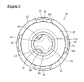
- FIG. 5 is a back view of the seal member in the attached state.
- FIG. 6 is a cross-sectional view taken along line VI-VI in FIG. 3 .
- FIG. 7 is a cross-sectional view taken along line VII-VII in FIG. 3 .
- FIG. 8 is a cross-sectional view taken along line VIII-VIII in FIG. 3 .
- FIG. 9 is a cross-sectional view taken along line IX-IX in FIG. 4 .
- FIG. 10 is a perspective view of a seal member in a state of being attached to a multi-core cable according to a second embodiment.
- FIG. 11 is an exploded perspective view of the seal member.
- FIG. 12 is a front view of the seal member in the attached state.
- FIG. 13 is a side view of the seal member in the attached state.
- FIG. 14 is a back view of the seal member in the attached state.
- FIG. 15 is a cross-sectional view taken along line XV-XV in FIG. 12 .
- FIG. 16 is a cross-sectional view taken along line XVI-XVI in FIG. 12 .
- FIG. 17 is a cross-sectional view taken along line XVII-XVII in FIG. 12 .
- FIG. 18 is a cross-sectional view taken along line XVIII-XVIII in FIG. 13 .
- a four-core cable is given as an example of a multi-core cable 10 , and application as, for example, a wire harness for an electrical parking brake installed in a vehicle is possible.
- a seal structure is constructed by attaching a seal member 20 to a terminal portion of the multi-core cable 10 .
- the multi-core cable 10 is a four-core round cable as described above, and has a structure in which four electrical wires 11 (referred to as a group of electrical wires 12 when appropriate) are enveloped by a sheath 15 that is made of an insulating resin.
- the electrical wires 11 are each a sheathed electrical wire constituted by a metal core wire that is covered by an insulating covering made of a synthetic resin, and the electrical wires 11 include two each of two types of electrical wires 11 L and 11 S that have different outer diameters.
- the two first electrical wires 11 L that have a larger diameter function as connection wires for connection to a motor for an electrical parking brake, and the two second electrical wires 11 S that have a smaller diameter function as signal lines for sensors in an anti-lock brake system.
- the terminal portion of the multi-core cable 10 is subjected to predetermined terminal processing such as stripping so as to have a structure in which the four electrical wires 11 L and 11 S are lead out and branched off from a terminal 15 A (see FIG. 6 ) of the sheath 15 , and as described above, the seal member 20 is attached to the terminal portion of the multi-core cable 10 having this structure.
- the seal member 20 is constituted to include a sheath rubber plug 30 that is tightly fitted around the terminal 15 A of the sheath 15 , an electrical wire rubber plug 40 through which the electrical wires 11 L and 11 S, which extend from the terminal 15 A of the sheath 15 , tightly pass, a housing 21 provided with attachment holes 23 and 25 into which the sheath rubber plug 30 and the electrical wire rubber plug 40 are respectively fitted, and a cap 50 that is attached to the housing 21 in order to retain the electrical wire rubber plug 40 .
- the sheath rubber plug 30 is shaped as a thick-walled cylinder that is tightly fitted around the terminal 15 A of the sheath 15 , and is provided with a plurality of inner circumferential lips 31 and a plurality of outer circumferential lips 32 on the inner peripheral surface and the outer peripheral surface respectively.
- a flange 34 that functions as a stopper is formed around the entirety of the outer circumference of the rear end (right end in FIG. 6 ) of the sheath rubber plug 30 .
- a tapered guiding surface 35 is formed on the inner circumference of the rear end of the sheath rubber plug 30 .
- the electrical wire rubber plug 40 is constituted by four individual rubber plugs 41 .
- the individual rubber plugs 41 include two each of two types of rubber plugs that have different sizes, namely a first rubber plug 41 L and a second rubber plug 41 S.
- the first rubber plugs 41 L that have a larger diameter are provided with first through-holes 42 L through which the first electrical wires 11 L, which are the electrical wires 11 that have a larger diameter, tightly pass.
- the second rubber plugs 41 S that have a smaller diameter are provided with second through-holes 42 S through which the second electrical wires 11 S, which have a smaller diameter, tightly pass.
- the first rubber plugs 41 L and the second rubber plugs 41 S both have the same length dimension in the axial direction.
- a plurality of inner circumferential lips 44 and a plurality of outer circumferential lips 45 are respectively formed on the inner peripheral surface and the outer peripheral surface of each of the individual rubber plugs 41 .
- the housing 21 is made of a synthetic resin, and is substantially shaped as a recumbent circular column.
- a rear attachment hole 23 into which the sheath rubber plug 30 can tightly fit, is formed in the rear end surface (right end surface in FIG. 6 ) of the housing 21 .
- the depth of the rear attachment hole 23 is set to a dimension that is a predetermined amount larger than the axial-direction length of the sheath rubber plug 30 .
- the outer diameter dimension of the housing 21 is the same as the outer diameter dimension of the flange 34 of the sheath rubber plug 30 .
- first attachment hole 25 L and a second attachment hole 25 S are formed in the front end surface of the housing 21 .
- the first attachment holes 25 L and the second attachment holes 25 S are shaped as bottomed holes having a depth dimension that matches the length of the first rubber plugs 41 L and the second rubber plugs 41 S.
- the two first attachment holes 25 L are formed vertically side-by-side with a predetermined gap therebetween in a region approximately on one side of the center line (vertical line) in the diameter direction of the housing 21
- the two second attachment holes 25 S are formed vertically side-by-side with a predetermined gap therebetween on the other side.
- first guide holes 27 L for guiding insertion of the first electrical wires 11 L are formed in the center of deep-side walls 26 L of the first attachment holes 25 L, and are open toward a deep-side space 24 of the above-described rear attachment hole 23 .
- second guide holes 27 S for guiding insertion of the second electrical wires 11 S are also formed in the center of deep-side walls 26 S of the second attachment holes 25 S, and are likewise open toward the deep-side space 24 of the above-described rear attachment hole 23 .
- the rear end portions of the guide holes 27 L and 27 S are formed with a tapered shape in order to guide the electrical wires 11 L and 11 S.
- the cap 50 is made of a synthetic resin, and as shown in FIG. 2 , is shaped as a circular lid that can be fitted to the front end surface of the housing 21 , or more specifically, a tubular portion 52 is formed over the entire circumference of a circumferential edge of a circular lid plate 51 .
- the lid plate 51 of the cap 50 is provided with two cylindrical protruding first insertion tubes 54 L that have a larger diameter and are for insertion of the first electrical wires 11 L, and two cylindrical protruding second insertion tubes 54 S that have a smaller diameter and are for insertion of the second electrical wires 11 S.
- the first insertion tubes 54 L and the second insertion tubes 54 S are arranged at positions that correspond to the above-described first attachment holes 25 L and second attachment holes 25 S.
- lock pieces 55 are formed on the tubular portion 52 of the cap 50 so as to protrude rearward at predetermined positions at 90-degree intervals.
- the lock pieces 55 each have a lock hole 56 and are capable of elastic deformation.
- tapered guide surfaces 55 A are formed on the inner surfaces of the protruding ends of the lock pieces 55 .
- lock protrusion portions 28 that can be fitted into the lock holes 56 of the lock pieces 55 are formed on the outer peripheral surface of the front end portion of the housing 21 so as to protrude from predetermined positions at 90-degree intervals.
- Rear end surfaces of the lock protrusion portions 28 are perpendicular locking surfaces 29 A, and the upper surfaces on the front side are tapered guide surfaces 29 B.
- the cap 50 is fitted to the front end surface of the housing 21 in a predetermined rotation orientation, the lock pieces 55 are elastically displaced and pressed by the guide surfaces 29 B of the lock protrusion portions 28 while sliding up them, and then when the lid plate 51 abuts against the front end surface of the housing 21 , the pressing is stopped, the lock pieces 55 return to their original position, and the lock protrusion portions 28 are fitted into the lock holes 56 , thus being locked.
- the first insertion tubes 54 L and the second insertion tubes 54 S formed on the lid plate 51 are arranged so as to be concentrically continuous with the corresponding first attachment holes 25 L and second attachment holes 25 S formed in the housing 21 .
- the sheath rubber plug 30 is placed around the terminal of the multi-core cable 10 and slid rearward by an appropriate distance.
- terminal processing is performed on the multi-core cable 10 , that is to say a predetermined length of the sheath 15 is stripped such that the four electrical wires 11 L and 11 S are lead out from the terminal 15 A of the remaining sheath 15 in an appropriately separated state.
- the sheath rubber plug 30 is slid forward and fitted around the terminal 15 A of the sheath 15 .
- the terminals of the electrical wires 11 L and 11 S are placed in the rear attachment hole 23 of the housing 21 , and then inserted into the corresponding first guide holes 27 L and second guide holes 27 S formed in the deep-side surface of the rear attachment hole 23 . Subsequently, the sheath rubber plug 30 is pushed into the rear attachment hole 23 of the housing 21 , and the terminals of the first electrical wires 11 L and the terminals of the second electrical wires 11 S are accordingly pushed forward so as to pass through the first attachment holes 25 L and the second attachment hole 25 S respectively. As shown in FIG.
- first through-holes 42 L of the first rubber plugs 41 L are fitted around the terminal sides of the first electrical wires 11 L that protrude from the first attachment holes 25 L
- second through-holes 42 S of the second rubber plugs 41 S are fitted around the terminal sides of the second electrical wires 11 S that protrude from the second attachment holes 25 S.
- the first rubber plugs 41 L and the second rubber plugs 41 S are slid along the first electrical wires 11 L and the second electrical wires 11 S and pressed into the corresponding first attachment holes 25 L and second attachment holes 25 S, and the pressing is stopped when they abut against the deep-side walls 26 L and 26 S as shown in FIG. 8 .
- the front surfaces of the first rubber plugs 41 L and the second rubber plugs are substantially flush with the front end surface of the housing 21 , and the attachment of the first rubber plugs 41 L and the second rubber plugs 41 S is complete.
- the inner circumferential lips 44 in the first through-holes 42 L of the first rubber plugs 41 L are elastically in close contact with the outer peripheral surfaces of the first electrical wires 11 L
- the outer circumferential lips 45 of the first rubber plugs 41 L are elastically in close contact with the inner peripheral surfaces of the first attachment holes 25 L
- the inner circumferential lips 44 in the second through-holes 42 S of the second rubber plugs 41 S are elastically in close contact with the outer peripheral surfaces of the second electrical wires 11 S
- the outer circumferential lips 45 of the second rubber plugs 41 S are elastically in close contact with the inner peripheral surfaces of the second attachment holes 25 S.
- the rotation orientation of the cap 50 is set to an orientation in which the pair of first insertion tubes 54 L and the pair of second insertion tubes 54 S substantially correspond to the pair of first attachment holes 25 L and the pair of second attachment holes 25 S respectively, and then the terminals of the first electrical wires 11 L and the terminals of the second electrical wires 11 S are respectively inserted into the first insertion tubes 54 L and the second insertion tubes 54 S from the back side. Thereafter, the cap 50 is moved along the electrical wires 11 L and 11 S and fitted to the front end surface of the housing 21 in the manner described previously. When the cap 50 is properly fitted, as shown in FIG.
- the lock protrusion portions 28 of the housing 21 are fitted into and locked to the corresponding lock holes 56 of the lock pieces 55 , thus retaining the total of four first rubber plugs 41 L and second rubber plugs 41 S, that is to say, firmly holding the sealed state of the regions around the total of four first electrical wires 11 L and second electrical wires 11 S.
- the terminals of the total of four first electrical wires 11 L and second electrical wires 11 S that extend from the terminal 15 A of the sheath 15 are drawn forward out from the corresponding first insertion tubes 54 L and second insertion tubes 54 S provided in the cap 50 . Additionally, the terminal 15 A of the sheath 15 is sealed by the sheath rubber plug 30 , and the regions around the first electrical wires 11 L and the second electrical wires 11 S are sealed by the first rubber plugs 41 L and the second rubber plugs 41 S.
- the sheath rubber plug 30 which is fitted around the terminal 15 A of the sheath 15 of the multi-core cable 10 , and the electrical wire rubber plug 40 (first rubber plugs 41 L and second rubber plugs 41 S), through which the electrical wires (first electrical wires 11 L and second electrical wires 11 S) that extend from the terminal 15 A of the sheath 15 pass, are fitted into the corresponding rear attachment hole 23 and front attachment hole 25 (first attachment holes 25 L and second attachment holes 25 S) provided in the housing 21 , thus sealing the terminal 15 A of the sheath 15 as well as the regions around the electrical wires 11 .
- the seal structure can be constructed in a shorter time than in the conventional case of using hot-melt resin, for example, thus making it possible to reduce manufacturing cost.
- a plurality of individual rubber plugs 41 (first rubber plugs 41 L and second rubber plugs 41 S) through which the electrical wires 11 L and 11 S individually pass are applied as the electrical wire rubber plug 40 , thus making it possible to more uniformly apply contact pressure over the entire circumference of each of the electrical wires 11 L and 11 S, and making it possible to obtain an improved seal.
- the electrical wire rubber plug 40 is constituted by four individual rubber plugs 41 , but a difference in the second embodiment is that an electrical wire rubber plug 70 is constituted by an integrated rubber plug.
- the following description focuses on differences, and members and portions having the same functions as in the first embodiment are appropriately given the same reference signs, thereby omitting or simplifying redundant descriptions.
- the electrical wire rubber plug 70 of the present embodiment is an integrated rubber plug as described above, and as shown in FIG. 11 , has a structure in which two first through-holes 73 L and two second through-holes 73 S, through which the larger-diameter first electrical wires 11 L and the smaller-diameter second electrical wires 11 S respectively pass, are formed in a single rubber plug main body 71 .
- the electrical wire rubber plug 70 has a shape in which the four individual rubber plugs 41 (two first rubber plugs 41 L and two second rubber plugs 41 S) illustrated in the first embodiment are aligned similarly to the alignment in the first embodiment, and then the abutting portions thereof are pressed inward together so as to be integrated, and the single rubber plug main body 71 is approximately shaped as a trapezoid having an upright base and rounded corners in a front view.
- Two first through-holes 73 L for the first electrical wires 11 L are formed with a predetermined gap therebetween in the region on the long side of the rubber plug main body 71
- two second through-holes 73 S for the second electrical wires 11 S are formed with a predetermined gap therebetween in the region on the short side.
- a plurality of inner circumferential lips 74 are formed on the inner peripheral surfaces of the first through-holes 73 L and the second through-holes 73 S. Also, a plurality of outer circumferential lips 75 are formed over the entire circumference of the outer peripheral surface of the rubber plug main body 71 .
- a single front attachment hole 60 into which the electrical wire rubber plug 70 can tightly fit, is formed in the front end surface of a housing 21 X.
- the inner peripheral surface of the front attachment hole 60 is formed with a shape that is congruent with the outer shape of the electrical wire rubber plug 70 , and the front attachment hole 60 is shaped as a bottomed hole having a depth dimension that matches the length of the electrical wire rubber plug 70 .
- the rear attachment hole 23 into which the sheath rubber plug 30 can tightly fit, is formed in the rear end surface of the housing 21 X.
- Two first guide holes 62 L for guiding insertion of the first electrical wires 11 L and two second guide holes 62 S for guiding insertion of the second electrical wires 11 S are formed in the deep-side wall of the front attachment hole 60 described above, and are open toward the deep-side space 24 of the rear attachment hole 23 .
- the formation locations of the first guide holes 62 L and the second guide holes 62 S are specifically on the same axial line as the first through-holes 73 L and the second through-holes 73 S of the electrical wire rubber plug 70 fitted into the front attachment hole 60 .
- the rear end portions of the first guide holes 62 L and the second guide holes 62 S are formed with a tapered shape in order to guide insertion.
- a cap 50 X is shaped as a circular lid that can be fitted to the front end surface of the housing 21 X.
- An insertion portion 80 for insertion of the four electrical wires 11 L and 11 S is formed so as to protrude from the lid plate 51 of the cap 50 X.
- the insertion portion 80 is block-shaped with an outer shape that is substantially congruent with the electrical wire rubber plug 70 .
- Two first insertion holes 81 L for insertion of the first electrical wires 11 L and two second insertion holes 81 S for insertion of the second electrical wires 11 S are formed in the insertion portion 80 , and the first insertion holes 81 L and the second insertion holes 81 S are arranged at positions that correspond to and are concentric with the first through-holes 73 L and the second through-holes 73 S of the electrical wire rubber plug 70 .
- the structure for attachment of the cap 50 X to the housing 21 X is similar to that of the first embodiment.
- terminal processing is performed on the multi-core cable 10 such that the four electrical wires 11 L and 11 S are lead out from the terminal 15 A of the sheath 15 in an appropriately separated state, and then the sheath rubber plug 30 is slid so as to be fitted around the terminal 15 A of the sheath 15 .
- the terminals of the electrical wires 11 L and 11 S are placed in the rear attachment hole 23 of the housing 21 X and then inserted into the corresponding first guide holes 62 L and second guide holes 62 S formed in the deep-side surface of the rear attachment hole 23 , and subsequently the sheath rubber plug 30 is pushed into the rear attachment hole 23 of the housing 21 X, and the terminals of the electrical wires 11 L and 11 S are accordingly pushed forward so as to pass through the front attachment hole 60 .
- the electrical wire rubber plug 70 is then attached to the terminals of the four electrical wires 11 L and 11 S that protrude from the front attachment hole 60 . Specifically, the terminals of the first electrical wire 11 L tightly pass through the first through-holes 73 L, and the terminals of the second electrical wires 11 S tightly pass through the second through-holes 73 S. Next, the electrical wire rubber plug 70 is slid along the four electrical wires 11 L and 11 Ss (group of electrical wires 12 ) and pressed into the front attachment hole 60 , and the pressing is stopped when the electrical wire rubber plug 70 abuts against the deep-side wall 61 . At this time, the front surface of the electrical wire rubber plug 70 is substantially flush with the front end surface of the housing 21 X, and attachment of the electrical wire rubber plug 70 is complete.
- the inner circumferential lips 74 in the first through-holes 73 L are elastically in close contact with the outer peripheral surfaces of the first electrical wires 11 L
- the inner circumferential lips 74 in the second through-holes 73 S are elastically in close contact with the outer peripheral surfaces of the second electrical wires 11 S
- the outer circumferential lips 75 provided on the outer circumference of the rubber plug main body 71 are elastically in close contact with the inner peripheral surface of the front attachment hole 60 . Accordingly, the regions around the total of four first electrical wires 11 L and second electrical wires 11 S are each sealed.
- the cap 50 X is attached.
- the rotation orientation of the cap 50 X is set to a predetermined rotation orientation, and then the terminals of the first electrical wires 11 L and the terminals of the second electrical wires 11 S are respectively inserted into the first insertion holes 81 L and the second insertion holes 81 S from the back side.
- the cap 50 X is moved along the group of electrical wires 12 and fitted to the front end surface of the housing 21 X, and when the cap 50 X is properly fitted, the lock protrusion portions 28 of the housing 21 X are fitted into and locked to the lock pieces 55 , thus retaining the electrical wire rubber plug 70 . This therefore firmly holds the sealed state of the region around the total of four first electrical wires 11 L and second electrical wires 11 S.
- the terminals of the total of four first electrical wires 11 L and second electrical wires 11 S that extend from the terminal 15 A of the sheath 15 are drawn forward out from the corresponding first insertion holes 81 L and second insertion holes 81 S provided in the cap 50 X. Additionally, the terminal 15 A of the sheath 15 is sealed by the sheath rubber plug 30 , and the regions around the first electrical wires 11 L and the second electrical wires 11 S are sealed by the electrical wire rubber plug 70 .
- the sheath rubber plug 30 which is fitted around the terminal 15 A of the sheath 15 of the multi-core cable 10 , and the electrical wire rubber plug 70 , through which the electrical wires 11 L and 11 S that extend from the terminal 15 A of the sheath 15 individually pass, are fitted into the corresponding rear attachment hole 23 and front attachment hole 60 provided in the housing 21 X, thus sealing the terminal 15 A of the sheath 15 as well as the regions around the electrical wires 11 . Due to likewise employing an assembly format, the seal structure can be constructed in a shorter time, thus making it possible to reduce manufacturing cost.
- the electrical wire rubber plug 70 is an integrated rubber plug, thus reducing the number of components, and also simplifying the assembly operation in that, for example, the operation of fitting the electrical wire rubber plug 70 into the front attachment hole 60 only needs to be performed one time, thus making it possible to further contribute to cost reduction.
- the two first through-holes 73 L and the two second through-holes 73 S are respectively arranged in a collective manner, or in other words, the two first through-holes 73 L and the two second through-holes 73 S are respectively arranged adjacent to each other.
- the second through-holes 73 S are arranged adjacent to each other, thus eliminating an insufficiency in contact pressure, and also having an advantage of obtaining uniform contact pressure over the entire circumference of the second through-holes 73 S.
- the manufacturing processes illustrated in the embodiments are merely examples, and other steps may be included.
- a configuration is possible in which the electrical wire rubber plug is attached in advance to the front attachment hole of the housing and retained with the cap, and thereafter the terminals of the electrical wires are inserted into the through-holes of the electrical wire rubber plug.
- the contact pressure applied to the outer circumference of the electrical wires can be further raised by employing a structure for compressing the electrical wire rubber plug in the axial direction.
- the number of electrical wires arranged in the multi-core cable is not limited to the four wires illustrated in the above embodiments, and any number of wires greater than or equal to two may be included.
- sheathed electrical wires examples include an electrical wire in which the core wire is a stranded wire in which a plurality of metal strands are twisted together, and a so-called single core wire constituted by a metal bar member. Also, the electrical wires may be shielded electrical wires.
- the multi-core cable may be a so-called cab tire cable, or may be a multi-core shielded wire in which a plurality of electrical wires are enveloped by a shielding layer.
- the terms “for example,” “e.g.,” “for instance,” “such as,” and “like,” and the verbs “comprising,” “having,” “including,” and their other verb forms, when used in conjunction with a listing of one or more components or other items, are each to be construed as open-ended, meaning that the listing is not to be considered as excluding other, additional components or items.
- Other terms are to be construed using their broadest reasonable meaning unless they are used in a context that requires a different interpretation.
Applications Claiming Priority (3)
| Application Number | Priority Date | Filing Date | Title |
|---|---|---|---|
| JP2015040018A JP6311938B2 (ja) | 2015-03-02 | 2015-03-02 | 多芯ケーブルのシール構造 |
| JP2015-040018 | 2015-03-02 | ||
| PCT/JP2016/055984 WO2016140173A1 (ja) | 2015-03-02 | 2016-02-29 | 多芯ケーブルのシール構造 |
Publications (2)
| Publication Number | Publication Date |
|---|---|
| US20180048081A1 US20180048081A1 (en) | 2018-02-15 |
| US10003141B2 true US10003141B2 (en) | 2018-06-19 |
Family
ID=56845325
Family Applications (1)
| Application Number | Title | Priority Date | Filing Date |
|---|---|---|---|
| US15/551,553 Active US10003141B2 (en) | 2015-03-02 | 2016-02-29 | Seal structure for multi-core cable |
Country Status (4)
| Country | Link |
|---|---|
| US (1) | US10003141B2 (ja) |
| JP (1) | JP6311938B2 (ja) |
| CN (1) | CN107801423B (ja) |
| WO (1) | WO2016140173A1 (ja) |
Cited By (4)
| Publication number | Priority date | Publication date | Assignee | Title |
|---|---|---|---|---|
| US10647271B2 (en) | 2018-05-10 | 2020-05-12 | Hitachi Metals, Ltd. | Wire harness |
| US10759359B1 (en) * | 2015-12-22 | 2020-09-01 | Autonetworks Technologies, Ltd. | Holding structure for cable |
| US10807543B2 (en) | 2018-05-18 | 2020-10-20 | Hitachi Metals, Ltd. | Wire harness |
| US11189961B2 (en) * | 2019-03-09 | 2021-11-30 | Suburban Marine, INC. | Modular harsh environment connector |
Families Citing this family (9)
| Publication number | Priority date | Publication date | Assignee | Title |
|---|---|---|---|---|
| US10756461B2 (en) * | 2017-05-30 | 2020-08-25 | Erico International Corporation | Adapter for splice block openings |
| DE102017121459B4 (de) * | 2017-09-15 | 2024-03-14 | Auto-Kabel Management Gmbh | Kabelabdichtung sowie Anordnung mit einem Gehäuse |
| JP6919577B2 (ja) * | 2018-01-16 | 2021-08-18 | 株式会社オートネットワーク技術研究所 | コネクタ |
| JP6996416B2 (ja) | 2018-05-11 | 2022-01-17 | 日立金属株式会社 | ワイヤハーネス及びその製造方法 |
| JP6947138B2 (ja) * | 2018-08-21 | 2021-10-13 | 株式会社オートネットワーク技術研究所 | 多芯ケーブルの止水構造 |
| JP7103960B2 (ja) * | 2019-01-15 | 2022-07-20 | 矢崎総業株式会社 | 防水構造 |
| JP6964105B2 (ja) * | 2019-03-14 | 2021-11-10 | ヒロセ電機株式会社 | コネクタおよびコネクタの組立方法 |
| JP7007332B2 (ja) * | 2019-06-14 | 2022-01-24 | 矢崎総業株式会社 | 防水コネクタ |
| AT17394U1 (de) * | 2020-10-29 | 2022-03-15 | Gebauer & Griller Kabelwerke Ges M B H | Kabelanordnung mit gehäuse |
Citations (13)
| Publication number | Priority date | Publication date | Assignee | Title |
|---|---|---|---|---|
| US2866957A (en) * | 1957-12-26 | 1958-12-30 | Essex Wire Corp | Cable connector |
| US5362258A (en) * | 1992-09-09 | 1994-11-08 | Wilo Gmbh | Cable-attaching device for a pump |
| US5387119A (en) * | 1993-10-08 | 1995-02-07 | Tescorp Seismic Products, Inc. | Waterproof electrical connector |
| US5542856A (en) * | 1994-04-11 | 1996-08-06 | Tescorp Seismic Products, Inc. | Field repairable electrical connector |
| US5885108A (en) * | 1994-12-01 | 1999-03-23 | A-G. Geophysical Products, Inc. | Electrical connector |
| US6165013A (en) * | 1999-01-08 | 2000-12-26 | Broussard; Blaine L. | Method and apparatus waterproofing |
| US6482036B1 (en) * | 2002-06-13 | 2002-11-19 | Blaine L. Broussard | Waterproof electrical connector |
| US7427715B2 (en) * | 2006-04-27 | 2008-09-23 | Hon Hai Precision Ind. Co., Ltd. | Cable assembly and method of making the same |
| JP2012182924A (ja) | 2011-03-02 | 2012-09-20 | Sumitomo Wiring Syst Ltd | 線間止水用のホットメルトブロックおよび該ホットメルトブロックを用いた多芯ケーブルの端末止水方法ならびに端末止水構造 |
| JP2012185960A (ja) | 2011-03-04 | 2012-09-27 | Yazaki Corp | コネクタ |
| US20130105219A1 (en) | 2011-10-28 | 2013-05-02 | Sumitomo Wiring Systems, Ltd. | Seal member and a charging connector provided therewith |
| JP2013134944A (ja) | 2011-12-27 | 2013-07-08 | Sumitomo Wiring Syst Ltd | コネクタ |
| JP2014238926A (ja) | 2013-06-06 | 2014-12-18 | 住友電装株式会社 | 防水コネクタ |
Family Cites Families (2)
| Publication number | Priority date | Publication date | Assignee | Title |
|---|---|---|---|---|
| JP3540156B2 (ja) * | 1998-06-10 | 2004-07-07 | 矢崎総業株式会社 | 防水コネクタ及び該防水コネクタの組付方法 |
| CN201954121U (zh) * | 2011-01-25 | 2011-08-31 | 南京蓝深制泵集团股份有限公司 | 一种用于潜水泵电缆密封和紧固装置 |
-
2015
- 2015-03-02 JP JP2015040018A patent/JP6311938B2/ja active Active
-
2016
- 2016-02-29 CN CN201680012539.6A patent/CN107801423B/zh active Active
- 2016-02-29 WO PCT/JP2016/055984 patent/WO2016140173A1/ja active Application Filing
- 2016-02-29 US US15/551,553 patent/US10003141B2/en active Active
Patent Citations (15)
| Publication number | Priority date | Publication date | Assignee | Title |
|---|---|---|---|---|
| US2866957A (en) * | 1957-12-26 | 1958-12-30 | Essex Wire Corp | Cable connector |
| US5362258A (en) * | 1992-09-09 | 1994-11-08 | Wilo Gmbh | Cable-attaching device for a pump |
| US5387119A (en) * | 1993-10-08 | 1995-02-07 | Tescorp Seismic Products, Inc. | Waterproof electrical connector |
| US5542856A (en) * | 1994-04-11 | 1996-08-06 | Tescorp Seismic Products, Inc. | Field repairable electrical connector |
| US5885108A (en) * | 1994-12-01 | 1999-03-23 | A-G. Geophysical Products, Inc. | Electrical connector |
| US6165013A (en) * | 1999-01-08 | 2000-12-26 | Broussard; Blaine L. | Method and apparatus waterproofing |
| US6482036B1 (en) * | 2002-06-13 | 2002-11-19 | Blaine L. Broussard | Waterproof electrical connector |
| US7427715B2 (en) * | 2006-04-27 | 2008-09-23 | Hon Hai Precision Ind. Co., Ltd. | Cable assembly and method of making the same |
| JP2012182924A (ja) | 2011-03-02 | 2012-09-20 | Sumitomo Wiring Syst Ltd | 線間止水用のホットメルトブロックおよび該ホットメルトブロックを用いた多芯ケーブルの端末止水方法ならびに端末止水構造 |
| JP2012185960A (ja) | 2011-03-04 | 2012-09-27 | Yazaki Corp | コネクタ |
| US20130337693A1 (en) | 2011-03-04 | 2013-12-19 | Yazaki Corporation | Connector |
| US20130105219A1 (en) | 2011-10-28 | 2013-05-02 | Sumitomo Wiring Systems, Ltd. | Seal member and a charging connector provided therewith |
| JP2013097898A (ja) | 2011-10-28 | 2013-05-20 | Sumitomo Wiring Syst Ltd | シール部材 |
| JP2013134944A (ja) | 2011-12-27 | 2013-07-08 | Sumitomo Wiring Syst Ltd | コネクタ |
| JP2014238926A (ja) | 2013-06-06 | 2014-12-18 | 住友電装株式会社 | 防水コネクタ |
Non-Patent Citations (1)
| Title |
|---|
| International Search Report and Written Opinion for application PCT/JP2016/055984 dated Apr. 26, 2017; 5 pages. |
Cited By (4)
| Publication number | Priority date | Publication date | Assignee | Title |
|---|---|---|---|---|
| US10759359B1 (en) * | 2015-12-22 | 2020-09-01 | Autonetworks Technologies, Ltd. | Holding structure for cable |
| US10647271B2 (en) | 2018-05-10 | 2020-05-12 | Hitachi Metals, Ltd. | Wire harness |
| US10807543B2 (en) | 2018-05-18 | 2020-10-20 | Hitachi Metals, Ltd. | Wire harness |
| US11189961B2 (en) * | 2019-03-09 | 2021-11-30 | Suburban Marine, INC. | Modular harsh environment connector |
Also Published As
| Publication number | Publication date |
|---|---|
| CN107801423A (zh) | 2018-03-13 |
| WO2016140173A1 (ja) | 2016-09-09 |
| CN107801423B (zh) | 2020-05-08 |
| US20180048081A1 (en) | 2018-02-15 |
| JP2016162584A (ja) | 2016-09-05 |
| JP6311938B2 (ja) | 2018-04-18 |
Similar Documents
| Publication | Publication Date | Title |
|---|---|---|
| US10003141B2 (en) | Seal structure for multi-core cable | |
| US20180041020A1 (en) | Seal structure for multiple-core cable | |
| US9842671B2 (en) | Seal member and seal structure for multicore cable | |
| US9972417B2 (en) | Electrically conducting path | |
| US9647370B2 (en) | Connector | |
| WO2012023314A1 (ja) | 端子金具 | |
| US9928939B1 (en) | Device and method for splicing shielded wire cables | |
| US11177056B2 (en) | Waterproofing structure and waterproofing method for shielded cable | |
| JP6172067B2 (ja) | 防水コネクタ | |
| JP2008067545A (ja) | シールド線の止水方法および止水構造 | |
| KR101768867B1 (ko) | 전기 접점 플러그 및 플러그 하우징 | |
| US20210167587A1 (en) | Hot melt block, cable manufacturing method, and cable | |
| US9837806B1 (en) | Seal structure for multicore cable, and seal member | |
| EP3619782B1 (en) | Spliced shielded wire cable and method of manufacturing same | |
| US9906003B1 (en) | Device and method for splicing shielded wire cables | |
| US11837834B2 (en) | Connector structure, and connector structure manufacturing method | |
| WO2017061249A1 (ja) | コネクタ | |
| US20150270696A1 (en) | Waterproofing structure for insulation-coated electrical wire, and wire harness | |
| US9614305B2 (en) | Connector | |
| JP5705429B2 (ja) | 防水用端子構造 | |
| US20210257823A1 (en) | Waterproof structure for multicore wire | |
| JP2002025651A (ja) | ケーブルのコネクタ接続構造 | |
| WO2024080137A1 (ja) | 配線部材 | |
| JP6202055B2 (ja) | シールド線のドレン線止水構造 | |
| JP5510738B2 (ja) | コネクタ |
Legal Events
| Date | Code | Title | Description |
|---|---|---|---|
| AS | Assignment |
Owner name: AUTONETWORKS TECHNOLOGIES, LTD., JAPAN Free format text: ASSIGNMENT OF ASSIGNORS INTEREST;ASSIGNORS:KOMORI, HIROKAZU;SAKATA, TOMOYUKI;HIGASHIKOZONO, MAKOTO;SIGNING DATES FROM 20170803 TO 20170804;REEL/FRAME:043310/0884 Owner name: SUMITOMO ELECTRIC INDUSTRIES, LTD., JAPAN Free format text: ASSIGNMENT OF ASSIGNORS INTEREST;ASSIGNORS:KOMORI, HIROKAZU;SAKATA, TOMOYUKI;HIGASHIKOZONO, MAKOTO;SIGNING DATES FROM 20170803 TO 20170804;REEL/FRAME:043310/0884 Owner name: SUMITOMO WIRING SYSTEMS, LTD., JAPAN Free format text: ASSIGNMENT OF ASSIGNORS INTEREST;ASSIGNORS:KOMORI, HIROKAZU;SAKATA, TOMOYUKI;HIGASHIKOZONO, MAKOTO;SIGNING DATES FROM 20170803 TO 20170804;REEL/FRAME:043310/0884 |
|
| STCF | Information on status: patent grant |
Free format text: PATENTED CASE |
|
| MAFP | Maintenance fee payment |
Free format text: PAYMENT OF MAINTENANCE FEE, 4TH YEAR, LARGE ENTITY (ORIGINAL EVENT CODE: M1551); ENTITY STATUS OF PATENT OWNER: LARGE ENTITY Year of fee payment: 4 |