RU61232U1 - WAGON PLATFORM - Google Patents
WAGON PLATFORM Download PDFInfo
- Publication number
- RU61232U1 RU61232U1 RU2006127156/22U RU2006127156U RU61232U1 RU 61232 U1 RU61232 U1 RU 61232U1 RU 2006127156/22 U RU2006127156/22 U RU 2006127156/22U RU 2006127156 U RU2006127156 U RU 2006127156U RU 61232 U1 RU61232 U1 RU 61232U1
- Authority
- RU
- Russia
- Prior art keywords
- beams
- frame
- braces
- side beams
- shortened
- Prior art date
Links
Abstract
Полезная модель относится к области железнодорожного транспорта и, в частности, к вагонам-платформам для перевозки крупнотоннажных контейнеров. Рама, на боковых балках которой установлены фитинговые упоры, состоит из двух концевых и средней частей, скрепленных между собой. Каждая концевая часть рамы содержит поперечные балки - шкворневую и торцевую, а также продольные - укороченную хребтовую и боковые. К укороченной хребтовой балке примыкают два раскоса, соединяющих ее со шкворневой балкой, и два раскоса, соединяющих ее с концами боковых балок. Боковые балки выполнены из профиля двутаврового сечения и выступают над укороченной хребтовой балкой. К их свободным концам приварены плоские заглушки, к которым закреплены поперечные связи, соединенные также с горизонтальными полками раскосов. Между заглушками концевых частей установлена средняя часть рамы, содержащая две боковые балки коробчатого сечения, соединенные между собой несколькими поперечными балками. При этом совмещены верхние полки стыкуемых частей, наружные вертикальные стенки боковых балок находятся в одной плоскости с вертикальными стенками двутавров концевых балок. В каждой боковой балке средней части рамы изготовлены по несколько продольных отверстий, облегчающих осмотр и обслуживание тормозного оборудования. Полезная модель позволяет также повысить технико-экономические показатели вагона, надежность в эксплуатации. 5 з.п.ф., 8 ил.The utility model relates to the field of railway transport and, in particular, to platform wagons for the transportation of large containers. The frame, on the side beams of which the fitting stops are installed, consists of two end and middle parts, fastened together. Each end part of the frame contains transverse beams - pivot and end, as well as longitudinal - shortened spinal and lateral. Two braces adjacent to the shortened spinal beam connecting it to the pivot beam, and two braces connecting it to the ends of the side beams. The lateral beams are made of an I-section and protrude above the shortened spinal beam. Flat caps are welded to their free ends, to which transverse connections are fixed, also connected to the horizontal shelves of the braces. Between the plugs of the end parts, the middle part of the frame is installed, containing two box-shaped side beams connected by several transverse beams. In this case, the upper shelves of the joined parts are combined, the outer vertical walls of the side beams are in the same plane as the vertical walls of the I-beams of the end beams. In each side beam of the middle part of the frame, several longitudinal holes are made to facilitate inspection and maintenance of brake equipment. The utility model also allows to increase the technical and economic indicators of the car, reliability in operation. 5 C.p.F., 8 ill.
Description
Полезная модель относится к области железнодорожного транспорта и, в частности, к вагонам-платформам для перевозки двух крупнотоннажных контейнеров типа 1А или комбинаций крупнотоннажных контейнеров меньшей вместимости.The utility model relates to the field of railway transport and, in particular, to platform wagons for the transportation of two large-capacity containers of type 1A or combinations of large-capacity containers of lower capacity.
Известны конструкции вагонов-платформ для перевозки крупнотоннажных контейнеров (RU 40974 U1, 18.05.2004; RU 48307 U1, 24.01.2005, RU 44611 U1, 27.02.2004). Рама таких вагонов представляет собой сварную конструкцию, содержащую сквозную хребтовую балку, боковые, шкворневые, торцевые и поперечные балки, а также установленные на ней фитинговые упоры для установки крупнотоннажных контейнеров.Known designs of flatcars for the transportation of large containers (RU 40974 U1, 05/18/2004; RU 48307 U1, 01/24/2005, RU 44611 U1, 02/27/2004). The frame of such cars is a welded structure containing a through spinal beam, side, pivot, end and transverse beams, as well as fitting stops mounted on it for the installation of large containers.
Длина этих вагонов и расположение фитинговых упоров позволяют перевозить только один крупнотоннажный контейнер типа 1А или один типа 1В или два контейнера типа 1C. Недостатком всех конструкций является высокая удельная металлоемкость.The length of these wagons and the location of the fitting stops allow only one type 1A large container or one type 1B or two type 1C containers to be transported. The disadvantage of all designs is the high specific metal consumption.
Известна также конструкция вагона-платформы модели 13-470, позволяющей перевозить один контейнер типа 1А и один - типа 1C или три - типа 1C или другие их комбинации (Пастухов И.Ф. и др. «Вагоны», М., Транспорт, 1988, стр.190-194). Рама платформы имеет мощные хребтовую и боковые балки, соединенные с двумя торцевыми, двумя шкворневыми, тремя основными и двумя дополнительными поперечными балками и четырьмя раскосами.Also known is the design of a platform car model 13-470, which allows one type 1A container and one type 1C container or three type 1C containers or other combinations thereof (Pastukhov I.F. et al. “Wagons”, M., Transport, 1988 , pp. 190-194). The platform frame has powerful spinal and side beams connected to two end, two pivot, three main and two additional transverse beams and four braces.
Однако эта конструкция не позволяет устанавливать и перевозить два контейнера типа 1А. Кроме того, высока ее удельная металлоемкость, что снижает технико-экономические показатели вагона.However, this design does not allow the installation and transport of two containers of type 1A. In addition, its specific metal consumption is high, which reduces the technical and economic indicators of the car.
Наиболее близким техническим решением к заявляемой полезной модели является железнодорожная платформа, в которой рама содержит хребтовую The closest technical solution to the claimed utility model is a railway platform, in which the frame contains a spinal
балку, торцевые, шкворневые и промежуточные поперечные балки, а также боковые балки, верхние части которых выступают над хребтовой, торцевыми, шкворневыми и промежуточными поперечными балками, расположенными в одной плоскости (RU 2262458 С1, 30.11.2004).beam, end, pivot and intermediate transverse beams, as well as side beams, the upper parts of which protrude above the spinal, end, pivot and intermediate transverse beams located in one plane (RU 2262458 C1, 11/30/2004).
Недостатком данной рамы является завышенная металлоемкость, что приводит к снижению грузоподъемности вагона.The disadvantage of this frame is the excessive metal consumption, which leads to a decrease in the carrying capacity of the car.
Кроме того, из-за применения высоких профилей усложнены доступ к тормозному оборудованию и его обслуживание.In addition, due to the use of high profiles, access to brake equipment and its maintenance are complicated.
Техническим результатом, на решение которого направлена полезная модель, является создание конструкции вагона-платформы, позволяющего перевозить два крупнотоннажных контейнера типа 1А или комбинации из крупнотоннажных контейнеров меньшей вместимости, снижение металлоемкости, повышение технико-экономических показателей вагона, а также облегчение доступа для осмотра и технического обслуживания тормозного оборудования.The technical result, which the utility model is aimed at, is to create a platform car design that allows transporting two large-capacity containers of type 1A or a combination of large-capacity containers of lower capacity, reducing metal consumption, increasing the technical and economic parameters of the car, and also facilitating access for inspection and technical service brake equipment.
Указанный технический результат достигается тем, что в вагоне-платформе для крупнотоннажных контейнеров, включающем ходовые части, автосцепное и тормозное оборудование, рама с фитинговыми упорами, установленными на боковых балках, выполнена из двух концевых и средней частей, скрепленных между собой, при этом каждая концевая часть рамы содержит поперечные балки - шкворневую и торцевую, а также продольные балки - укороченную хребтовую и боковые, причем к укороченной хребтовой балке примыкают два раскоса, соединяющих ее со шкворневой балкой, и два раскоса, соединяющих ее с концами боковых балок, выполненных из профиля двутаврового сечения, соединенного со шкворневой и торцевой балками и выступающего над укороченной хребтовой балкой.The specified technical result is achieved by the fact that in the platform car for large containers, including running gears, coupler and brake equipment, the frame with fitting stops mounted on the side beams is made of two end and middle parts, fastened together, with each end part of the frame contains transverse beams - pivot and end, as well as longitudinal beams - a shortened spinal and side, and two braces adjacent to the shortened spinal beam connecting it to the pivot beam d, and two braces connecting it to the ends of the side beams made of an I-section profile connected to the pivot and end beams and protruding above the shortened spinal beam.
При этом к торцам свободных концов боковых балок жестко закреплены плоские заглушки, к которым примыкают концы раскосов, соединенных с укороченной хребтовой балкой, и поперечные связи, соединенные горизонтальными полками соответственно с верхней и нижней полками раскосов, At the same time, flat caps are rigidly fixed to the ends of the free ends of the side beams, to which the ends of the braces adjacent to the shortened spinal beam and transverse connections connected by horizontal shelves respectively to the upper and lower shelves of the braces are adjacent,
при этом раскосы и боковые балки в местах соединения с заглушками усилены горизонтальными и вертикальными ребрами, а места соединения раскосов с укороченными хребтовыми балками - листовыми накладками. Средняя часть рамы содержит две боковые балки, жестко соединенные между собой несколькими поперечными балками, каждая боковая балка выполнена коробчатой, в ее вертикальных стенках изготовлены по несколько продольных отверстий, и своей торцевой частью примыкает к заглушке соответствующей боковой балки концевой части рамы с совмещением верхних полок стыкуемых балок, причем наружная вертикальная стенка коробчатого профиля установлена в одной плоскости с вертикальной стенкой двутаврового профиля, а внутренняя вертикальная стенка боковой балки средней части совмещена с вертикальной стенкой раскоса укороченной хребтовой балки.while the braces and side beams at the junction with the plugs are reinforced with horizontal and vertical ribs, and the junction of the braces with shortened spinal beams - sheet overlays. The middle part of the frame contains two side beams rigidly interconnected by several transverse beams, each side beam is box-shaped, several longitudinal holes are made in its vertical walls, and its end part adjoins the plug of the corresponding side beam of the end part of the frame with the matching upper shelves of the joined beams, and the outer vertical wall of the box-shaped profile is installed in the same plane as the vertical wall of the I-beam profile, and the inner vertical wall of the sides Oh beam middle part combined with a vertical brace wall of a shortened spinal beam.
Раскосы, соединяющие укороченные хребтовые балки с боковыми балками средней части рамы, выполнены из зетобразного профиля, при этом верхние полки профиля обращены к боковым балкам.The braces connecting the shortened spinal beams to the side beams of the middle part of the frame are made of a zeta-shaped profile, with the upper shelves of the profile facing the side beams.
Боковые балки концевых и средней частей рамы выступают над укороченными хребтовыми балками на величину, равную 0,23-0,25 высоты боковых балок средней части рамы.The lateral beams of the end and middle parts of the frame protrude above the shortened spinal beams by an amount equal to 0.23-0.25 of the height of the side beams of the middle part of the frame.
В нижних листовых накладках в местах соединения раскосов с укороченными хребтовыми балками выполнены отверстия, усиленные приварными шайбами.Holes reinforced with welded washers are made in the lower leaf plates at the junction of the braces with shortened spinal beams.
Ширина плоских заглушек боковых балок концевых частей рамы равна ширине полок коробчатого профиля боковых балок средней части рамы.The width of the flat plugs of the side beams of the end parts of the frame is equal to the width of the shelves of the box-shaped profile of the side beams of the middle part of the frame.
Профиль боковых балок концевых частей рамы в нижней части имеет переменную высоту с увеличением к средней части рамы.The profile of the side beams of the end parts of the frame in the lower part has a variable height with an increase towards the middle part of the frame.
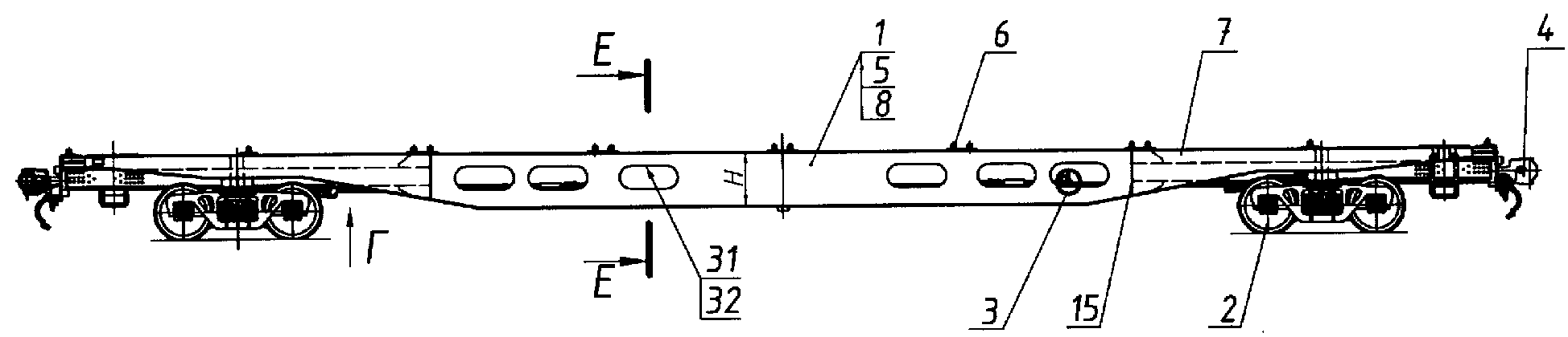
На фиг.1 изображен общий вид вагона-платформы,Figure 1 shows a General view of the wagon platform
на фиг.2 - вид сверху,figure 2 is a top view
на фиг.3 - выносной элемент А на фиг.2,figure 3 - remote element A in figure 2,
на фиг.4 - разрез Б-Б на фиг.3,figure 4 is a section bB in figure 3,
на фиг.5 - выносной элемент Д на фиг.3,figure 5 - remote element D in figure 3,
на фиг.6 - вид Г на фиг.1,in Fig.6 is a view of G in Fig.1,
на фиг.7 - разрез В-В на фиг.3,figure 7 - section bb in figure 3,
на фиг.8 - разрез Е-Е на фиг.1.in Fig.8 is a section EE in Fig.1.
Вагон-платформа состоит из рамы 1, установленной на ходовые части 2, тормозного 3 и автосцепного 4 оборудования. На боковых балках 5 рамы установлены фитинговые упоры 6. Рама состоит из двух концевых 7 и средней 8 частей, скрепленных между собой. Концевая часть 7 рамы содержит поперечные балки - шкворневую 9 и торцевую 10, а также продольные балки - укороченную хребтовую 11 и боковые 12. К укороченной хребтовой балке 11 примыкают два раскоса 13, соединяющие ее со шкворневой балкой 9, и два раскоса 14, соединяющих ее с концами боковых балок 12. Боковые балки 12 выполнены из профиля двутаврового сечения и соединены со шкворневой 9 и торцевой 10 балками и выступают над укороченной хребтовой балкой 11. К торцам свободных концов боковых балок 12 жестко закреплены плоские заглушки 15, к которым примыкают концы раскосов 14, а также поперечные связи 16, 17, соединенных соответственно с верхними 18 и нижними 19 полками раскосов 14. Раскосы 14 и боковые балки 12 в местах соединения с заглушками 15 усилены горизонтальными 20 и вертикальными 21, 22 ребрами, а места соединения раскосов с укороченными хребтовыми балками 11 - листовыми накладками 23, 24.The wagon platform consists of a frame 1 mounted on the chassis 2, brake 3 and couplings 4 equipment. On the side beams 5 of the frame, fitting stops are installed 6. The frame consists of two end 7 and middle 8 parts, fastened together. The end part 7 of the frame contains cross beams - pivot 9 and end 10, as well as longitudinal beams - a shortened spinal 11 and side 12. To the shortened spinal beam 11 there are two braces 13 connecting it to the pivot beam 9, and two braces 14 connecting it with the ends of the side beams 12. The side beams 12 are made of an I-section and connected to the pivot 9 and the end 10 of the beams and protrude above the shortened spinal beam 11. To the ends of the free ends of the side beams 12 are fixed flat plugs 15, which are adjacent the ends of the braces 14, as well as the transverse connections 16, 17, respectively connected with the upper 18 and lower 19 shelves of the braces 14. The braces 14 and the side beams 12 at the junctions with caps 15 are reinforced with horizontal 20 and vertical 21, 22 ribs, and the joints of the braces with shortened spinal beams 11 - sheet overlays 23, 24.
Средняя часть 8 рамы 1 содержит две боковые балки 25, жестко соединенных между собой поперечными балками 26, 27, 28, на которых закреплено тормозное оборудование 3. Каждая боковая балка 25 выполнена коробчатой, в ее вертикальных стенках 29 и 30 изготовлены по несколько продольных отверстий 31, зашитых по периметру перемычками 32. Отверстия снижают массу рамы и дают возможность производить осмотр и обслуживание тормозного оборудования. Средняя часть 8 рамы 1 торцами боковых балок 25 примыкает к заглушкам 15 концевых частей 7 рамы и жестко с ними соединяется. При этом совмещены верхние полки 33 и 34 соединяемых боковых The middle part 8 of the frame 1 contains two side beams 25, rigidly interconnected by transverse beams 26, 27, 28, on which the brake equipment 3 is fixed. Each side beam 25 is box-shaped, several longitudinal holes 31 are made in its vertical walls 29 and 30 sewn around the perimeter by jumpers 32. Holes reduce the mass of the frame and make it possible to inspect and service the brake equipment. The middle part 8 of the frame 1 with the ends of the side beams 25 adjoins the plugs 15 of the end parts 7 of the frame and is rigidly connected to them. In this case, the upper shelves 33 and 34 of the connected side
балок 12 и 25, наружные вертикальные стенки 29 боковых балок 25 установлены в одной плоскости с вертикальными стенками 35 боковых балок 12, а внутренние вертикальные стенки 30 боковых балок 25 установлены напротив торцов 36 вертикальных стенок 37 раскосов 14.beams 12 and 25, the outer vertical walls 29 of the side beams 25 are installed in the same plane with the vertical walls 35 of the side beams 12, and the inner vertical walls 30 of the side beams 25 are installed opposite the ends 36 of the vertical walls 37 of the braces 14.
Раскосы 14, соединяющие укороченные хребтовые балки 11 концевых частей 7 с боковыми балками 25 средней части 8 рамы, выполнены из зетобразного профиля, при этом его верхние полки 18 обращены к боковым балкам 12.The braces 14 connecting the shortened spinal beams 11 of the end parts 7 to the side beams 25 of the middle part 8 of the frame are made of a zeta profile, with its upper shelves 18 facing the side beams 12.
Боковые балки 12 концевых 7 и боковые балки 25 средней частей рамы выступают над укороченными хребтовыми балками 11 на величину h, равную 0,23-0,25 высоты Н боковых балок средней части рамы.The side beams 12 of the end 7 and the side beams 25 of the middle parts of the frame protrude above the shortened spinal beams 11 by a value of h equal to 0.23-0.25 of the height H of the side beams of the middle part of the frame.
В листовых накладках 24, усиливающих места соединения раскосов 14 с укороченными хребтовыми балками, выполнены отверстия 38, усиленные приварными шайбами 39.In the sheet plates 24, reinforcing the junction of the braces 14 with the shortened spinal beams, holes 38 are made, reinforced with welded washers 39.
Ширина плоских заглушек 15, установленных на концах боковых балок 12, равна ширине полок 34 боковых балок 25 средней части 8 рамы.The width of the flat plugs 15 mounted on the ends of the side beams 12 is equal to the width of the shelves 34 of the side beams 25 of the middle part 8 of the frame.
Боковые балки 12 концевых частей 7 имеют по длине переменную высоту: меньшую у торцевой балки 10 с увеличением к шкворневой балке 9 и дальнейшим увеличением к средней части 8 рамы.The lateral beams 12 of the end parts 7 have a variable height along the length: smaller at the end beam 10 with an increase to the pivot beam 9 and a further increase to the middle part 8 of the frame.
Предложенный вагон-платформа и расположение фитинговых упоров 6 обеспечивает установку и перевозку двух крупнотоннажных контейнеров типа 1А и различных комбинаций крупнотоннажных контейнеров меньшей вместимости.The proposed wagon platform and the location of the fitting stops 6 provides for the installation and transportation of two large containers of type 1A and various combinations of large containers of smaller capacity.
При этом обеспечивается высокая прочность, более высокие технико-экономические показатели вагона-платформы, удобство обслуживания и надежность в эксплуатации.This ensures high strength, higher technical and economic performance of the flat car, ease of maintenance and reliability in operation.
В настоящее время производится подготовка к его серийному производству.Currently, preparations are underway for its mass production.
Claims (6)
Priority Applications (1)
| Application Number | Priority Date | Filing Date | Title |
|---|---|---|---|
| RU2006127156/22U RU61232U1 (en) | 2006-07-26 | 2006-07-26 | WAGON PLATFORM |
Applications Claiming Priority (1)
| Application Number | Priority Date | Filing Date | Title |
|---|---|---|---|
| RU2006127156/22U RU61232U1 (en) | 2006-07-26 | 2006-07-26 | WAGON PLATFORM |
Publications (1)
| Publication Number | Publication Date |
|---|---|
| RU61232U1 true RU61232U1 (en) | 2007-02-27 |
Family
ID=37991004
Family Applications (1)
| Application Number | Title | Priority Date | Filing Date |
|---|---|---|---|
| RU2006127156/22U RU61232U1 (en) | 2006-07-26 | 2006-07-26 | WAGON PLATFORM |
Country Status (1)
| Country | Link |
|---|---|
| RU (1) | RU61232U1 (en) |
Cited By (5)
| Publication number | Priority date | Publication date | Assignee | Title |
|---|---|---|---|---|
| RU190798U1 (en) * | 2019-06-14 | 2019-07-12 | РЕЙЛ 1520 АйПи ЛТД | Rail vehicle frame |
| RU194256U1 (en) * | 2019-08-05 | 2019-12-04 | Общество с ограниченной ответственностью "Всесоюзный научно-исследовательский центр транспортных технологий" (ООО "ВНИЦТТ") | FRAMEWORK DESIGN OF THE FREIGHT WAGON |
| RU202485U1 (en) * | 2020-11-27 | 2021-02-19 | Акционерное общество "Рузаевский завод химического машиностроения" (АО "Рузхиммаш") | Freight car frame |
| RU207327U1 (en) * | 2021-07-23 | 2021-10-22 | Акционерное общество "Рузаевский завод химического машиностроения" (АО "Рузхиммаш") | Rail platform frame |
| RU223940U1 (en) * | 2023-10-31 | 2024-03-07 | Общество С Ограниченной Ответственностью "Рейл1520 Ай Пи" (Ооо "Рейл1520 Ай Пи") | RAILWAY VEHICLE |
-
2006
- 2006-07-26 RU RU2006127156/22U patent/RU61232U1/en not_active IP Right Cessation
Cited By (5)
| Publication number | Priority date | Publication date | Assignee | Title |
|---|---|---|---|---|
| RU190798U1 (en) * | 2019-06-14 | 2019-07-12 | РЕЙЛ 1520 АйПи ЛТД | Rail vehicle frame |
| RU194256U1 (en) * | 2019-08-05 | 2019-12-04 | Общество с ограниченной ответственностью "Всесоюзный научно-исследовательский центр транспортных технологий" (ООО "ВНИЦТТ") | FRAMEWORK DESIGN OF THE FREIGHT WAGON |
| RU202485U1 (en) * | 2020-11-27 | 2021-02-19 | Акционерное общество "Рузаевский завод химического машиностроения" (АО "Рузхиммаш") | Freight car frame |
| RU207327U1 (en) * | 2021-07-23 | 2021-10-22 | Акционерное общество "Рузаевский завод химического машиностроения" (АО "Рузхиммаш") | Rail platform frame |
| RU223940U1 (en) * | 2023-10-31 | 2024-03-07 | Общество С Ограниченной Ответственностью "Рейл1520 Ай Пи" (Ооо "Рейл1520 Ай Пи") | RAILWAY VEHICLE |
Similar Documents
| Publication | Publication Date | Title |
|---|---|---|
| RU2329906C2 (en) | Car-platform | |
| RU183178U1 (en) | RAILWAY FRAME | |
| RU2288121C1 (en) | Railway platform for carrying large-size containers | |
| RU157920U1 (en) | Gondola with unloading hatches | |
| RU184883U1 (en) | RAIL CONSOLE OF THE RAILWAY PLATFORM | |
| CN104228858B (en) | Transport vehicle and vehicle body thereof | |
| US7954437B2 (en) | Railroad well car with open truss sides | |
| RU61232U1 (en) | WAGON PLATFORM | |
| RU108013U1 (en) | SIDE WAGON WALL | |
| RU186428U1 (en) | JOINTED WAGON CAR | |
| RU2391239C1 (en) | Freight gondola car with dead floor | |
| RU2345918C1 (en) | Gondola wagon of aluminium alloys | |
| US10336347B2 (en) | Railroad well car with open truss sides | |
| RU183177U1 (en) | BEAM SIDE FRAME OF THE RAILWAY PLATFORM | |
| RU202485U1 (en) | Freight car frame | |
| CN202138384U (en) | Broad-track universal open locomotive with flip-down lower side door | |
| RU2475389C1 (en) | Railway long-wheelbase platform for large-capacity containers | |
| RU49778U1 (en) | RAILWAY TANK | |
| CN111114563B (en) | Railway common flat car | |
| RU172308U1 (en) | Rail car frame | |
| RU122624U1 (en) | RAILWAY PLATFORM | |
| UA20725U (en) | Flatcar | |
| RU160611U1 (en) | INDOOR WAGON HOPPER FOR CARRIAGE OF BULK CARGOES | |
| CN204341032U (en) | A kind of railway transport open car | |
| CN101219730B (en) | Container top cover and container using the top cover |
Legal Events
| Date | Code | Title | Description |
|---|---|---|---|
| MM1K | Utility model has become invalid (non-payment of fees) |
Effective date: 20080727 |