RU2690341C2 - Agitator assembly and container for transportation and storage of liquids, equipped with such unit of mixer - Google Patents
Agitator assembly and container for transportation and storage of liquids, equipped with such unit of mixer Download PDFInfo
- Publication number
- RU2690341C2 RU2690341C2 RU2017131897A RU2017131897A RU2690341C2 RU 2690341 C2 RU2690341 C2 RU 2690341C2 RU 2017131897 A RU2017131897 A RU 2017131897A RU 2017131897 A RU2017131897 A RU 2017131897A RU 2690341 C2 RU2690341 C2 RU 2690341C2
- Authority
- RU
- Russia
- Prior art keywords
- container
- working elements
- holder
- working
- rotation
- Prior art date
Links
- 239000007788 liquid Substances 0.000 title claims abstract description 24
- 238000002156 mixing Methods 0.000 claims abstract description 15
- 239000002861 polymer material Substances 0.000 claims abstract description 6
- 239000012530 fluid Substances 0.000 claims description 13
- 239000000463 material Substances 0.000 claims description 11
- 229920001940 conductive polymer Polymers 0.000 claims description 5
- 230000008878 coupling Effects 0.000 claims description 4
- 238000010168 coupling process Methods 0.000 claims description 4
- 238000005859 coupling reaction Methods 0.000 claims description 4
- 230000002093 peripheral effect Effects 0.000 claims description 4
- 230000007704 transition Effects 0.000 claims description 3
- 230000000694 effects Effects 0.000 abstract description 3
- 238000009434 installation Methods 0.000 abstract description 3
- 239000000126 substance Substances 0.000 abstract 1
- 238000003756 stirring Methods 0.000 description 3
- 238000001746 injection moulding Methods 0.000 description 2
- 230000006641 stabilisation Effects 0.000 description 2
- 238000011105 stabilization Methods 0.000 description 2
- 230000005540 biological transmission Effects 0.000 description 1
- 238000011109 contamination Methods 0.000 description 1
- 230000001419 dependent effect Effects 0.000 description 1
- 238000005516 engineering process Methods 0.000 description 1
- 239000000945 filler Substances 0.000 description 1
- 238000004519 manufacturing process Methods 0.000 description 1
- 238000000034 method Methods 0.000 description 1
- 238000000465 moulding Methods 0.000 description 1
Images
Classifications
-
- B—PERFORMING OPERATIONS; TRANSPORTING
- B01—PHYSICAL OR CHEMICAL PROCESSES OR APPARATUS IN GENERAL
- B01F—MIXING, e.g. DISSOLVING, EMULSIFYING OR DISPERSING
- B01F27/00—Mixers with rotary stirring devices in fixed receptacles; Kneaders
- B01F27/05—Stirrers
- B01F27/051—Stirrers characterised by their elements, materials or mechanical properties
- B01F27/054—Deformable stirrers, e.g. deformed by a centrifugal force applied during operation
- B01F27/0542—Deformable stirrers, e.g. deformed by a centrifugal force applied during operation deformable by centrifugal force
-
- B—PERFORMING OPERATIONS; TRANSPORTING
- B01—PHYSICAL OR CHEMICAL PROCESSES OR APPARATUS IN GENERAL
- B01F—MIXING, e.g. DISSOLVING, EMULSIFYING OR DISPERSING
- B01F27/00—Mixers with rotary stirring devices in fixed receptacles; Kneaders
-
- B—PERFORMING OPERATIONS; TRANSPORTING
- B01—PHYSICAL OR CHEMICAL PROCESSES OR APPARATUS IN GENERAL
- B01F—MIXING, e.g. DISSOLVING, EMULSIFYING OR DISPERSING
- B01F27/00—Mixers with rotary stirring devices in fixed receptacles; Kneaders
- B01F27/05—Stirrers
- B01F27/051—Stirrers characterised by their elements, materials or mechanical properties
- B01F27/053—Stirrers characterised by their elements, materials or mechanical properties characterised by their materials
-
- B—PERFORMING OPERATIONS; TRANSPORTING
- B01—PHYSICAL OR CHEMICAL PROCESSES OR APPARATUS IN GENERAL
- B01F—MIXING, e.g. DISSOLVING, EMULSIFYING OR DISPERSING
- B01F27/00—Mixers with rotary stirring devices in fixed receptacles; Kneaders
- B01F27/05—Stirrers
- B01F27/07—Stirrers characterised by their mounting on the shaft
- B01F27/072—Stirrers characterised by their mounting on the shaft characterised by the disposition of the stirrers with respect to the rotating axis
- B01F27/0726—Stirrers characterised by their mounting on the shaft characterised by the disposition of the stirrers with respect to the rotating axis having stirring elements connected to the stirrer shaft each by a single radial rod, other than open frameworks
-
- B—PERFORMING OPERATIONS; TRANSPORTING
- B01—PHYSICAL OR CHEMICAL PROCESSES OR APPARATUS IN GENERAL
- B01F—MIXING, e.g. DISSOLVING, EMULSIFYING OR DISPERSING
- B01F27/00—Mixers with rotary stirring devices in fixed receptacles; Kneaders
- B01F27/05—Stirrers
- B01F27/11—Stirrers characterised by the configuration of the stirrers
- B01F27/117—Stirrers provided with conical-shaped elements, e.g. funnel-shaped
-
- B—PERFORMING OPERATIONS; TRANSPORTING
- B01—PHYSICAL OR CHEMICAL PROCESSES OR APPARATUS IN GENERAL
- B01F—MIXING, e.g. DISSOLVING, EMULSIFYING OR DISPERSING
- B01F27/00—Mixers with rotary stirring devices in fixed receptacles; Kneaders
- B01F27/05—Stirrers
- B01F27/11—Stirrers characterised by the configuration of the stirrers
- B01F27/118—Stirrers in the form of brushes, sieves, grids, chains or springs
-
- B—PERFORMING OPERATIONS; TRANSPORTING
- B01—PHYSICAL OR CHEMICAL PROCESSES OR APPARATUS IN GENERAL
- B01F—MIXING, e.g. DISSOLVING, EMULSIFYING OR DISPERSING
- B01F33/00—Other mixers; Mixing plants; Combinations of mixers
- B01F33/86—Mixing heads comprising a driven stirrer
-
- B—PERFORMING OPERATIONS; TRANSPORTING
- B01—PHYSICAL OR CHEMICAL PROCESSES OR APPARATUS IN GENERAL
- B01F—MIXING, e.g. DISSOLVING, EMULSIFYING OR DISPERSING
- B01F35/00—Accessories for mixers; Auxiliary operations or auxiliary devices; Parts or details of general application
-
- B—PERFORMING OPERATIONS; TRANSPORTING
- B01—PHYSICAL OR CHEMICAL PROCESSES OR APPARATUS IN GENERAL
- B01F—MIXING, e.g. DISSOLVING, EMULSIFYING OR DISPERSING
- B01F35/00—Accessories for mixers; Auxiliary operations or auxiliary devices; Parts or details of general application
- B01F35/40—Mounting or supporting mixing devices or receptacles; Clamping or holding arrangements therefor
- B01F35/41—Mounting or supporting stirrer shafts or stirrer units on receptacles
- B01F35/411—Mounting or supporting stirrer shafts or stirrer units on receptacles by supporting only one extremity of the shaft
- B01F35/4111—Mounting or supporting stirrer shafts or stirrer units on receptacles by supporting only one extremity of the shaft at the top of the receptacle
-
- B—PERFORMING OPERATIONS; TRANSPORTING
- B01—PHYSICAL OR CHEMICAL PROCESSES OR APPARATUS IN GENERAL
- B01F—MIXING, e.g. DISSOLVING, EMULSIFYING OR DISPERSING
- B01F2215/00—Auxiliary or complementary information in relation with mixing
- B01F2215/04—Technical information in relation with mixing
- B01F2215/0413—Numerical information
- B01F2215/0418—Geometrical information
- B01F2215/0422—Numerical values of angles
Landscapes
- Chemical & Material Sciences (AREA)
- Chemical Kinetics & Catalysis (AREA)
- Mixers Of The Rotary Stirring Type (AREA)
- Accessories For Mixers (AREA)
Abstract
Description
Область техники, к которой относится изобретениеThe technical field to which the invention relates.
Изобретение относится к узлу мешалки, который предназначен для присоединения к мешалке, комбинируемой с контейнером для жидкостей, при этом указанный контейнер имеет в верхней стенке закрываемое крышкой заливочное отверстие для заполнения контейнера, а узел мешалки содержит стержневой держатель рабочих элементов, выполненный в виде пустотелого вала для ввода в него вала мешалки, в то время как рабочие элементы соединены с возможностью поворота с держателем рабочих элементов таким образом, чтобы свободный конец указанных рабочих элементов в монтажной конфигурации находился в повернутом положении относительно оси вращения держателя рабочих элементов.The invention relates to a stirrer assembly, which is intended to be connected to a stirrer combined with a container for liquids, wherein said container has a filling opening to be closed by a lid for filling the container, and the stirrer assembly comprises a rod holder of working elements made in the form of a hollow shaft inserting the agitator shaft into it, while the working elements are pivotally connected with the holder of the working elements so that the free end of the specified working elements Ntov in the mounting configuration was in a rotated position relative to the axis of rotation of the holder of the work items.
Уровень техникиThe level of technology
Узел мешалки указанного в начале типа известен из ЕР 2620210 А1. Рабочие элементы известного узла мешалки в монтажной конфигурации, в которой узел мешалки может устанавливаться в контейнер для жидкостей, находятся в повернутом положении относительно держателя рабочих элементов и в этом положении присоединены к держателю рабочих элементов при помощи стопорного соединения.An agitator assembly of the type indicated at the outset is known from EP 2620210 A1. The operating elements of the known agitator assembly in the mounting configuration, in which the agitator assembly can be installed in a container for liquids, are in a rotated position relative to the holder of the operating elements and in this position are attached to the holder of the operating elements by means of a locking connection.
Для перевода в рабочую конфигурацию, в которой концы рабочих элементов находятся в позиции, радиально удаленной от держателя рабочих элементов, указанные рабочие элементы приходится поворачивать вручную.To translate into a working configuration, in which the ends of the working elements are in a position radially distant from the holder of the working elements, these working elements must be rotated manually.
Раскрытие сущности изобретенияDisclosure of the invention
Задача настоящего изобретения заключается в том, чтобы обеспечить узел мешалки указанного вначале типа, который позволяет автоматически осуществлять перевод рабочих элементов из монтажной конфигурации в рабочую конфигурацию.The object of the present invention is to provide a stirrer assembly of the type indicated at the beginning, which allows automatic transfer of the working elements from the mounting configuration to the working configuration.
Эта задача решена при помощи узла мешалки с признаками, указанными в пункте 1 формулы изобретения.This problem is solved by using the mixer assembly with the features indicated in
Согласно изобретению между рабочими элементами и держателем рабочих элементов установлено пружинное устройство, таким образом, чтобы рабочие элементы в рабочей конфигурации вследствие вращения держателя рабочих элементов занимали наклонное положение, зависимое от скорости вращения держателя рабочих элементов, с углом 6 перемешивания относительно оси вращения, при этом свободные концы рабочих элементов находятся на расстоянии r перемешивания от оси вращения, а усилие пружины возрастает при увеличении угла перемешивания.According to the invention, a spring device is installed between the working elements and the holder of the working elements, so that the working elements in the working configuration due to the rotation of the holder of the working elements occupy an inclined position dependent on the speed of rotation of the holder of the working elements, with an angle of 6 mixing with respect to the axis of rotation, while the ends of the working elements are at a distance r of mixing from the axis of rotation, and the force of the spring increases with increasing angle of mixing.
Согласно изобретению автоматическое разворачивание рабочих элементов осуществляется таким образом, чтобы во время работы узла мешалки концы рабочих элементов под действием на них центробежной силы поворачивались и устанавливались на расстоянии перемешивания от оси вращения. Благодаря этому, можно осуществлять не только перевод рабочих элементов из монтажной конфигурации в рабочую конфигурацию без ручного управления. При помощи выбора подходящей скорости вращения узла мешалки можно настраивать требуемое расстояние концов рабочих элементов от держателя рабочих элементов. Усилие пружины действует в качестве возвратной силы, которая противодействует центробежной силе и при уменьшении скорости вращения обеспечивает возвращение концов рабочих элементов к оси вращения. Благодаря этому, в частности, обеспечивается возможность перемешивания содержащихся в контейнере остатков жидкостей, которые собираются в ограниченной области у дна контейнера, не опасаясь соударений концов рабочих элементов со стенками контейнера. Следствием возвратного действия пружины является также тот факт, что рабочие элементы, выполненные даже из материала малой плотности, не могут всплывать в жидкости, имеющей сравнимую плотность, но эффективно работают в такой жидкости на требуемой глубине перемешивания.According to the invention, the automatic unfolding of the working elements is carried out in such a way that, during the operation of the mixer assembly, the ends of the working elements under the action of the centrifugal force on them rotate and set at a distance of mixing from the axis of rotation. Due to this, it is possible to carry out not only the transfer of work items from the mounting configuration to the working configuration without manual control. By selecting the appropriate speed of rotation of the stirrer assembly, you can adjust the required distance of the ends of the working elements from the holder of the working elements. The force of the spring acts as a return force, which counteracts the centrifugal force and, with a decrease in the rotational speed, ensures the return of the ends of the working elements to the axis of rotation. This, in particular, makes it possible to mix the residual liquids contained in the container, which are collected in a limited area at the bottom of the container without fear of collisions of the ends of the working elements with the walls of the container. A consequence of the spring back action is also the fact that work items made even from a low-density material cannot float up in a liquid having a comparable density, but effectively work in such a liquid at the required depth of mixing.
Особенно предпочтительно, чтобы свободные концы рабочих элементов в монтажной конфигурации были расположены под поворотными опорами, предусмотренными на держателе рабочих элементов, поскольку при этом рабочие элементы в монтажной конфигурации могут непосредственно поворачиваться относительно друг друга, при этом можно минимизировать поперечное сечение в области развернутых относительно друг друга рабочих элементов, что является важным для ввода узла мешалки в контейнер через заливочное отверстие контейнера.It is particularly preferable that the free ends of the working elements in the mounting configuration are located under the pivot bearings provided on the holder of the working elements, since the working elements in the mounting configuration can be directly rotated relative to each other, while minimizing the cross-section working elements, which is important for entering the mixer assembly into the container through the filling opening of the container.
Если пружинное устройство выполнено в виде пружины кручения, можно дополнительно обеспечить вышеуказанную минимизацию поперечного сечения, поскольку пружина кручения может быть установлена радиально снаружи от рабочих элементов с минимально возможной радиально выступающей частью.If the spring device is designed as a torsion spring, the above minimization of the cross section can additionally be ensured, since the torsion spring can be installed radially outside the working elements with the smallest possible radially protruding part.
Одно плечо пружины кручения предпочтительно опирается выше поворотной опоры на держателе рабочих элементов, в то время как другое плечо пружины кручения опирается на рабочий элемент.One shoulder of the torsion spring preferably rests above the pivot bearing on the holder of the work elements, while the other shoulder of the torsion spring rests on the work element.
В другом предпочтительном варианте осуществления пружинное устройство выполнено в виде спиральной пружины, которая требует минимального установочного пространства. При этом один конец спиральной пружины может быть расположен на поворотной цапфе поворотной опоры, а другой конец - на рабочем элементе.In another preferred embodiment, the spring device is made in the form of a coil spring, which requires minimal installation space. In this case, one end of the coil spring can be located on the pivot pin of the pivot bearing, and the other end on the working element.
Если пружинное устройство выполнено в виде электропроводного соединения между держателем рабочих элементов и рабочим элементом, можно получить надежное электростатическое ответвление, независимое от перемешиваемой жидкости, через рабочие элементы в держатель рабочих элементов.If the spring device is made in the form of an electrically conductive connection between the holder of the working elements and the working element, it is possible to obtain a reliable electrostatic branch, independent of the mixed liquid, through the working elements into the holder of the working elements.
Особенно предпочтительно, чтобы пружинное устройство было выполнено из электропроводного полимерного материала, при этом в одном особенно предпочтительном варианте осуществления узел мешалки вместе со всеми его компонентами может быть изготовлен из полимерного материала, предпочтительно - из электропроводного полимерного материала.Particularly preferably, the spring device was made of an electrically conductive polymer material, while in one particularly preferred embodiment, the agitator assembly, together with all its components, may be made of a polymeric material, preferably of an electrically conductive polymeric material.
Если пружинное устройство выполнено в виде выступа материала на рабочем элементе, то такое пружинное устройство можно получить вместе с рабочим элементом при помощи одного технологического процесса, например, процесса литья под давлением. Кроме того, при этом осуществляется целостное соединение между пружинным устройством и рабочим элементом, поэтому можно отказаться от специальных, отдельно изготовленных соединительных устройств.If the spring device is made in the form of a protrusion of the material on the working element, then such a spring device can be obtained together with the working element using a single technological process, for example, an injection molding process. In addition, this provides a holistic connection between the spring device and the work item, so you can refuse special, separately manufactured connecting devices.
Это относится также к соединению пружинного устройства с держателем рабочих элементов, когда пружинное устройство свободным соединительным концом соединяется с геометрическим замыканием с держателем рабочих элементов, например, при помощи стопорного соединения.This also applies to the connection of the spring device with the holder of the working elements, when the spring device with a free connecting end is connected with a positive interlock with the holder of the working elements, for example, by means of a locking connection.
Также независимо от конструкции пружинного устройства, применяемого для узла мешалки, в случае узла мешалки указанного вначале типа предпочтительно, чтобы рабочие элементы были изготовлены из электропроводного полимерного материала.Also, regardless of the design of the spring device used for the agitator assembly, in the case of the agitator assembly of the type initially mentioned, it is preferable that the working elements are made of an electrically conductive polymeric material.
Кроме того, независимо от конструкции пружинного устройства, применяемого для узла мешалки, предпочтительно также, чтобы рабочие элементы имели опорный конец и свободный конец, соединенный перемычкой с опорным концом и образующий проточную трубку, при этом указанная проточная трубка имеет трубчатую стенку.In addition, regardless of the design of the spring device used for the agitator assembly, it is also preferable that the working elements have a support end and a free end connected by a jumper to the support end and forming a flow tube, wherein said flow tube has a tubular wall.
Благодаря тому, что конец рабочего элемента образует проточную трубку, обеспечивается стабилизация вращающегося конца рабочего элемента в направлении набегающего потока при вращении в текучей среде.Due to the fact that the end of the working element forms a flow tube, stabilization of the rotating end of the working element in the direction of the incident flow during rotation in a fluid medium is ensured.
Если трубчатая стенка выполнена таким образом, что в сечении перемычки, перпендикулярном продольной оси перемычки, над осью трубки длина трубчатой стенки в направлении набегающего потока больше, чем под осью трубки, то над осью трубки образуется более длинный профиль в направлении набегающего потока, чем под осью набегающего потока, таким образом, подъемная сила жидкости, действующая на концы рабочих элементов, повышается, что приводит к стабилизации концов рабочих элементов в потоке жидкости во время работы.If the tubular wall is designed in such a way that, in a cross section perpendicular to the longitudinal axis of the bridge, the length of the tubular wall in the flow direction is longer than under the tube axis, a longer profile in the flow direction is formed over the tube axis than under the flow axis the incident flow, thus, the lifting force of the fluid acting on the ends of the working elements increases, which leads to stabilization of the ends of the working elements in the liquid flow during operation.
Если при этом плоскость действия подъемной силы жидкости, образованной верхней частью трубчатой стенки имеет угол наклона к направлению набегающего потока, то, выбирая соответствующий угол наклона в зависимости от скорости вращения узла мешалки, можно получить требуемую подъемную силу жидкости, действующую на концы рабочих элементов. Благодаря этому можно, например, при подходящем выборе угла наклона оптимально приспособить узел мешалки к вязкости или иным структурным свойствам перемешиваемых жидкостей.If at the same time the plane of action of the lifting force of the fluid formed by the upper part of the tubular wall has an angle of inclination to the flow direction, then choosing the appropriate angle of slope depending on the speed of rotation of the agitator unit, you can get the desired lifting force of the fluid acting on the ends of the working elements. This makes it possible, for example, with a suitable choice of the angle of inclination to optimally adapt the stirrer assembly to the viscosity or other structural properties of the mixed liquids.
Предпочтительно, чтобы трубчатая стенка была выполнена в виде наклонного конуса, при этом входное поперечное сечение проточной трубки имеет наклон по отношению к выходному поперечному сечению проточной трубки, вследствие чего подъемная сила жидкости также может оказывать влияние.Preferably, the tubular wall is made in the form of an inclined cone, wherein the inlet cross section of the flow tube is inclined with respect to the outlet cross section of the flow tube, as a result of which the lifting force of the fluid can also have an effect.
Если проточная трубка имеет во входном поперечном сечении подпорный порог с кольцеобразной подпорной поверхностью, которая примыкает к поверхности перемычки, в зависимости от формы и величины подпорной поверхности можно получить для рабочего элемента требуемое сопротивление набегающему потоку.If the flow tube has a retaining threshold in the inlet cross section with a ring-shaped retaining surface that is adjacent to the jumper surface, depending on the shape and size of the retaining surface, you can obtain for the working element the desired resistance to the incident flow.
Особенно предпочтительно, чтобы подпорная поверхность могла иметь наклон относительно оси вращения в направлении набегающего потока, тогда при помощи угла наклона подпорной поверхности можно регулировать сопротивление набегающему потоку независимо от величины подпорной поверхности.Particularly preferably, the retaining surface can have an inclination relative to the axis of rotation in the direction of the incident flow, then with the help of the inclination angle of the retaining surface it is possible to adjust the resistance to the incoming flow regardless of the size of the retaining surface.
Подпорная поверхность предпочтительно содержит по меньшей мере один сегмент, который имеет наклон относительно плоской части подпорной поверхности, образуя известный из аэродинамики или аэромеханики закрылок, позволяющий получать в определенном месте эффективную дополнительную подъемную силу жидкости, которая оказывает влияние на относительное положение конца рабочего элемента в поле набегающего потока.The retaining surface preferably contains at least one segment that has a slope of a relatively flat part of the retaining surface, forming a flap known from aerodynamics or aeromechanics, which allows to obtain in a certain place an effective additional lifting force of the fluid, which affects the relative position of the end of the working element in the incident field flow.
При этом в зависимости от перемешиваемой среды некоторые диапазоны могут оказаться предпочтительными для углов наклона сегментов поверхности. Так, например, угол β1, β2 наклона сегмента поверхности предпочтительно составляет от 5 до 90°, в частности, от 5 до 45°, более предпочтительно - от 5 до 20°, в частности, от 10 до 15°, и наиболее предпочтительно - 10°.However, depending on the mixed medium, some ranges may be preferable for the slope angles of the surface segments. For example, the angle β 1 , β 2 the slope of the surface segment is preferably from 5 to 90 °, in particular from 5 to 45 °, more preferably from 5 to 20 °, in particular from 10 to 15 °, and most preferably 10 °.
В зависимости от требуемого направления действия особой подъемной силы жидкости, получаемой при помощи установленного сегмента поверхности, указанный сегмент поверхности может иметь наклон в направлении, противоположном направлению набегающего потока, или в направлении набегающего потока.Depending on the desired direction of action of a particular lifting force of the fluid, obtained by means of an established surface segment, the specified surface segment may be inclined in the direction opposite to the flow direction, or in the flow direction.
Особенно предпочтительно, чтобы сегмент поверхности имел изменяемый наклон относительно плоской части подпорной поверхности, что позволяет адаптировать действие подъемной силы жидкости, создаваемой указанным сегментом поверхности, к соответствующей среде, перемешиваемой при помощи мешалки.Particularly preferably, the surface segment has a variable slope relative to the flat part of the retaining surface, which allows you to adapt the effect of the lifting force of the fluid created by the specified surface segment to the corresponding medium stirred by the agitator.
Сегмент поверхности предпочтительно выполняется в виде кольцевого сегмента таким образом, чтобы наружная кромка сегмента поверхности была образована периферийным краем подпорной поверхности, а соединительная кромка сегмента поверхности на переходе к плоской части поверхности проходила по касательной к входному поперечному сечению проточной трубки.The surface segment is preferably in the form of an annular segment so that the outer edge of the surface segment is formed by the peripheral edge of the retaining surface, and the connecting edge of the surface segment at the transition to the flat part of the surface is tangential to the inlet cross section of the flow tube.
В том случае, если при помощи сегментов поверхности на конце рабочего элемента должен возникать момент подъемной силы жидкости, предпочтительно, чтобы подпорная поверхность содержала два сегмента поверхности, которые предпочтительно расположены напротив друг друга.In the event that with the help of surface segments at the end of the working element a moment of lifting force of the liquid should occur, it is preferable that the supporting surface contains two surface segments that are preferably opposite each other.
Углы β1, β2 наклона сегментов поверхности предпочтительно равны друг другу по абсолютной величине.The angles β 1 , β 2 of the slope of the surface segments are preferably equal to each other in absolute value.
Для получения момента подъемной силы жидкости может также быть предпочтительным, чтобы один сегмент поверхности имел наклон в направлении набегающего потока, а другой сегмент поверхности - против направления набегающего потока.To obtain the moment of the lifting force of the fluid, it may also be preferable that one surface segment has an inclination in the direction of the flow and another segment of the surface against the direction of the flow.
Если в средней части перемычки предусмотрен подъемный карман с подъемной поверхностью, которая имеет угол наклона относительно оси вращения в направлении набегающего потока и угол разворота в направлении противоположном, направлению набегающего потока, выбирая подходящий угол, можно оказывать влияние на величину подъемной силы жидкости или сопротивление набегающему потоку рабочего элемента, благодаря соответствующей конструкции поверхности перемычки.If a lifting pocket with a lifting surface is provided in the middle part of the bridge, which has an angle of inclination relative to the axis of rotation in the direction of the incident flow and an angle of rotation in the direction opposite to the direction of the incident flow, choosing an appropriate angle can influence the amount of fluid lifting force or resistance to the incident flow working element, thanks to the appropriate design of the surface of the lintel.
Держатель рабочих элементов на верхнем осевом конце предпочтительно содержит соединительное устройство для соединения с крышкой, при этом указанное соединительное устройство имеет осевой упор для опорной кромки, которая образована в основании гнезда, предусмотренного в крышке для установки заглушки, и которая ограничивает сквозное отверстие, предусмотренное в основании. Благодаря этому, при помощи крышки можно соединять рабочий узел мешалки с контейнером независимо от типа используемой мешалки. При этом рабочий узел мешалки может быть постоянно расположен или установлен в контейнере без необходимости принудительного соединения мешалки с рабочим узлом.The holder of the working elements at the upper axial end preferably comprises a connecting device for connecting to the lid, wherein said connecting device has an axial abutment for the supporting edge, which is formed at the base of the socket provided in the lid for installing the plug, and which limits the through hole provided at the base . Due to this, with the help of a lid it is possible to connect the working unit of the mixer with the container, regardless of the type of mixer used. At the same time, the working unit of the mixer can be permanently located or installed in the container without the necessity of forcibly connecting the mixer to the working unit.
Описанный выше предпочтительный вариант осуществления узла мешалки с расположенным на его верхнем осевом конце соединительным устройством является также независимым от других конструкций держателя рабочих элементов, а также независимым от наличия или отсутствия пружинного устройства между рабочими элементами и держателем рабочих элементов или от конструкции рабочих элементов, что является полезным.The preferred embodiment of the agitator assembly described above, with a connecting device located at its upper axial end, is also independent of other structures of the work item holder, as well as independent of the presence or absence of a spring device between the work items and the work item holder or of the work item design, which is helpful.
Если упор вышеуказанного соединительного устройства выполнен в виде стопорного кольца, устанавливаемого в гнезде стопорного кольца соединительного устройства, то его можно особенно просто изготовить, и, кроме того, вариант осуществления упора в виде стопорного кольца, которое прилегает к опорной кромке, при необходимости позволяет осуществлять вращательное движение между узлом мешалки и крышкой. Стопорное кольцо предпочтительно лежит на опорной кромке только во время остановки узла мешалки, в то время как при вращении узла мешалки относительно крышки стопорное кольцо поднимается с опорной кромки, чтобы исключить трение, и, в частности, связанный с трением износ, чтобы таким образом предотвратить возможные загрязнения жидкости, находящейся в контейнере.If the stop of the above-mentioned connecting device is made in the form of a locking ring that is installed in the slot of the locking ring of the connecting device, then it can be made particularly simply, and, in addition, an embodiment of the stop in the form of a locking ring that abuts against the supporting edge, if necessary, allows rotational movement between the stirrer assembly and the lid. The circlip preferably lies on the supporting edge only during the stopping of the agitator assembly, while during the rotation of the agitator assembly relative to the lid, the circlip rises from the supporting edge to eliminate friction and, in particular, wear associated with friction, in order to prevent possible contamination of the fluid in the container.
Посадочный элемент для стопорного кольца предпочтительно представляет собой отдельную деталь, которая соединяется с держателем рабочих элементов для получения соединительного устройства с геометрическим замыканием.The landing element for the retaining ring is preferably a separate part, which is connected to the holder of the working elements to obtain a locking device.
Альтернативно этому возможно также использование посадочного элемента для стопорного кольца, выполненного как единое целое с держателем рабочих элементов.Alternatively, it is also possible to use a landing element for a locking ring, which is made as one piece with the holder of the working elements.
Особенно предпочтительно, чтобы посадочный элемент для стопорного кольца был выполнен в виде выступа материала на держателе рабочих элементов, что можно осуществить, например, путем его формования на контуре держателя рабочих элементов.Particularly preferably, the landing element for the retaining ring was made in the form of a protrusion of the material on the holder of the working elements, which can be done, for example, by molding it on the contour of the holder of the working elements.
Если держатель рабочих элементов содержит на нижнем осевом конце соединительное устройство, выполненное в виде вала-ступицы, для соединения рабочих элементов, при этом указанное соединительное устройство соединяется с геометрическим замыканием с держателем рабочих элементов и содержит опорные цапфы для соединения с рабочими элементами и получения поворотных опор, то держатель рабочих элементов можно изготовить особенно просто по сравнению со сложными соединительными устройствами, изготавливаемыми отдельно. При этом конструкция соединительного устройства на держателе рабочих элементов при простом изготовлении может обеспечивать соединение с геометрическим замыканием между соединительным устройством и держателем рабочих элементов.If the holder of the working elements contains at the lower axial end a connecting device made in the form of a shaft-hub for connecting the working elements, the specified connecting device is connected with the positive coupling with the holder of the working elements and contains supporting pins for connecting with the working elements and obtaining pivoting bearings , the holder of the working elements can be made particularly simple compared to complex connecting devices, manufactured separately. In this case, the design of the connecting device on the holder of the working elements with simple manufacture can provide a connection with a positive fit between the connecting device and the holder of the working elements.
Особенно предпочтительно, чтобы указанное соединительное устройство одновременно служило для соединения с валом мешалки.Particularly preferably, the specified connecting device at the same time served for connection with the shaft of the agitator.
Если соединение соединительного устройства с валом мешалки представляет собой соединение с геометрическим замыканием, то такое соединение можно осуществлять простым способом без помощи инструмента.If the connection between the coupling device and the agitator shaft is a positive-locking connection, this connection can be made in a simple way without the aid of a tool.
Соединительное устройство предпочтительно содержит первое соединительное устройство с геометрическим замыканием для передачи вращающего момента от вала мешалки на рабочие элементы и второе соединительное устройство для осевого закрепления соединительного устройства на валу мешалки, таким образом, при помощи соединительных устройств с геометрическим замыканием обеспечивается не только надежная передача вращающего момента от вала мешалки к узлу мешалки, но также и закрепление определенной осевой относительной позиции между валом мешалки и узлом мешалки.The connecting device preferably comprises a first connecting device with a positive locking for transmitting torque from the agitator shaft to the working elements and a second connecting device for axially securing the connecting device to the agitator shaft, thus not only the reliable transmission of the torque from the agitator shaft to the agitator assembly, but also securing a specific axial relative position between the shaft eshalki and agitator assembly.
Узел мешалки предпочтительно выполнен таким образом, чтобы он был соединен с крышкой и вместе с этой крышкой в виде монтажного блока входил в заливочное отверстие контейнера, а также соединялся с контейнером при помощи соединения крышки с заливочным отверстием контейнера, таким образом, при его соединении с контейнером можно получать прочно соединенную комбинацию узла мешалки с контейнером путем простой замены стандартной крышки, расположенной на заливочном отверстии контейнера, на крышку, соединенную с узлом мешалки в виде монтажного блока.The agitator assembly is preferably designed in such a way that it is connected to the lid and, together with this lid, in the form of a mounting block enters the filling opening of the container, and also connects to the container by connecting the cover to the filling opening of the container, thus connecting it to the container A firmly connected combination of a mixer assembly with a container can be obtained by simply replacing the standard cap located on the container filling hole with a cover connected to the mixer assembly as an assembly block.
Для закрепления соединения крышки с узлом мешалки и исключения отсоединения крышки от узла мешалки крышка предпочтительно снабжена заглушкой, которая устанавливается в гнездо для заглушки, предусмотренное в крышке, таким образом, стопорное кольцо оказывается в ограниченной с двух сторон в осевом направлении полости узла мешалки, выполненного в виде монтажного блока.To secure the connection of the lid to the agitator assembly and to avoid detaching the lid from the agitator assembly, the lid is preferably provided with a plug that fits into the plug slot provided in the lid, thus the retaining ring is bounded on both sides in the axial direction of the cavity of the agitator assembly as a mounting block.
Настоящее изобретение относится также к контейнеру для транспортирования и хранения жидкостей с контейнером, выполненным в виде внутреннего контейнера из полимерного материала, который содержит в верхней стенке закрываемое крышкой заливочное отверстие для заполнения контейнера, а на передней стороне - сливной штуцер для присоединения выпускной арматуры, а также нижнюю стенку, которая соединяет друг с другом две боковые стенки, заднюю стенку и переднюю стенку контейнера и служит для опоры контейнера на основание транспортного поддона, снабженное наружной оболочкой для установки контейнера, при этом крышка контейнера снабжена узлом мешалки в соответствии с описанными выше предпочтительными вариантами осуществления.The present invention also relates to a container for transporting and storing liquids with a container made in the form of an internal container made of polymeric material, which contains in its upper wall a lid with a filling opening for filling the container, and on the front side a drain connection for connecting the outlet fittings, and the bottom wall, which connects with each other the two side walls, the rear wall and the front wall of the container and serves to support the container on the base of the transport pallet, provided with an outer casing for mounting the container, wherein the container lid is provided with a stirrer assembly in accordance with the preferred embodiments described above.
Краткое описание чертежейBrief Description of the Drawings
Ниже приведено более подробное описание изобретения со ссылками на прилагаемые чертежи, на которых показаны:Below is a more detailed description of the invention with reference to the accompanying drawings, which show:
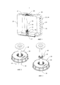
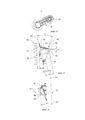
фиг. 1 - вид в продольном разрезе контейнера, используемого для транспортировки и хранения жидкостей и представленного как внутренний контейнер, с узлом мешалки в монтажной конфигурации;FIG. 1 is a longitudinal sectional view of a container used for transporting and storing liquids and presented as an internal container with a stirrer assembly in a mounting configuration;
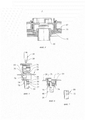
фиг. 2 - частичное изображение верхнего осевого конца узла мешалки с фиг. 1 со вставленным валом мешалки;FIG. 2 is a partial depiction of the upper axial end of the mixer assembly of FIG. 1 with agitator shaft inserted;
фиг. 3 - узел мешалки с фиг. 2 с валом мешалки, поднятым в осевом направлении;FIG. 3 shows the mixer assembly of FIG. 2 with the shaft of the agitator raised in the axial direction;
фиг. 4 - частичное изображение узла мешалки с фиг. 1 в транспортном положении в увеличенном масштабе;FIG. 4 is a partial depiction of the mixer assembly of FIG. 1 in a transport position on an enlarged scale;
фиг. 5 - изображение в разобранном виде другого варианта осуществления узла мешалки;FIG. 5 is an exploded image of another embodiment of the mixer assembly;
фиг. 6 - узел мешалки с фиг. 5 в собранном виде;FIG. 6 shows the mixer assembly of FIG. 5 assembled;
фиг. 7 - альтернативная конструкция соединительного устройства, расположенного на верхнем осевом конце узла мешалки;FIG. 7 shows an alternative design of a connecting device located at the upper axial end of the mixer assembly;
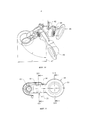
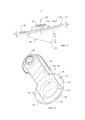
фиг. 8 - нижний осевой конец узла мешалки с фиг. 1 в увеличенном масштабе с множеством рабочих элементов;FIG. 8 is the lower axial end of the mixer assembly of FIG. 1 on an enlarged scale with many work items;
фиг. 9 - вид рабочих элементов с фиг. 8 в разрезе по оси IX-IX;FIG. 9 is a view of the working elements of FIG. 8 in section along the axis IX-IX;
фиг. 10 - вид рабочих элементов с фиг. 8 в рабочей конфигурации;FIG. 10 is a view of the working elements of FIG. 8 in working configuration;
фиг. 11 - вид сверху одного рабочего элемента;FIG. 11 is a top view of a single work item;
фиг. 12 - вид сзади в изометрии рабочего элемента с фиг. 11;FIG. 12 is a rear isometric view of the operating element of FIG. eleven;
фиг. 13 - вид рабочего элемента с фиг. 11 в разрезе по оси XIII-XIII;FIG. 13 is a view of the operating element of FIG. 11 in a section along the axis XIII-XIII;
фиг. 14 - вид рабочего элемента с фиг. 11 в разрезе по оси XIV-XIV;FIG. 14 is a view of the operating element of FIG. 11 in a section along the axis XIV-XIV;
фиг. 15 - вид сбоку другого варианта осуществления рабочего элемента;FIG. 15 is a side view of another embodiment of the work item;
фиг. 16 - вид в изометрии рабочего элемента с фиг. 15.FIG. 16 is a view in isometric of the operating element of FIG. 15.
Осуществление изобретенияThe implementation of the invention
На фиг. 1 показан внутренний контейнер 20 не представленного более подробно контейнера для транспортировки и хранения жидкостей. Контейнер 20 содержит примыкающие к нижней стенке 21 переднюю стенку 22, две противоположных боковых стенки 23, 24, заднюю стенку 25, а также противоположную нижней стенке 21 верхнюю стенку 26, при этом нижняя стенка 21 служит для опоры на не показанное основание транспортировочного поддона, снабженное также не показанной сетчатой оболочкой, на которую устанавливается контейнер 20.FIG. Figure 1 shows the
Верхняя стенка 26 снабжена заливным штуцером 27, который закрывается крышкой 28, выполненной в данном случае в виде резьбовой крышки.The
В показанном примере осуществления крышка 28 образует компонент узла 29 мешалки, который в качестве важных компонентов содержит также держатель 30 рабочих элементов в виде пустотелого вала, изготовленного в данном случае из электропроводного полимерного материала, а также блок 31 рабочих элементов, содержащий в данном варианте осуществления три рабочих элемента 32, которые при помощи ступицы 33 вала соединены с держателем 30 рабочих элементов.In the illustrated embodiment, the
Как следует из общего рассмотрения фиг. 1, 8 и 10, между рабочими элементами 32 и держателем 30 рабочих элементов предусмотрено пружинное устройство, выполненное в данном случае в виде пружины 34 кручения, которая в данном случае через ступицу 33 вала присоединена к держателю 30 рабочих элементов, при этом ступица вала для соединения с геометрическим замыканием со свободными концами 35 плеч пружины 34 кручения содержит фиксаторы 36, которые защелкиваются на выступах 37, образованных на концах 35 плеч. Пружины 34 кручения в данном случае выполнены как единое целое с рабочими элементами 32, при этом в показанном варианте осуществления неразъемное соединение пружин 34 кручения с рабочими элементами 32 обеспечивается, благодаря тому, что рабочие элементы 32 изготавливаются вместе с пружинами 34 кручения способом литья под давлением. В предварительно напряженном состоянии пружины кручения имеют S-образную форму.As follows from the general consideration of FIG. 1, 8 and 10, between the working
Пружины 34 кручения, как и рабочие элементы 32 и ступица 33 вала, а также держатель 30 рабочих элементов изготавливаются из электропроводного полимерного материала.The torsion springs 34, as well as the working
На фиг. 1 и 8 показан узел мешалки в монтажной конфигурации, в которой не происходит вращения держателя 30 рабочих элементов при помощи вала 38 мешалки, который жестко соединен через ступицу 33 вала с держателем 30 рабочих элементов, и который, как показано на фиг. 2, вводится сверху в держатель 30 рабочих элементов, при этом, как показано на фиг. 5, цапфа 39, предусмотренная на нижнем осевом конце вала 38 мешалки, вводится в показанное на фиг. 9, гнездо 40 цапфы вала, выполненное в ступице 33 вала. Для осевого закрепления соединения, передающего крутящий момент между валом 38 мешалки и ступицей 33 вала, предусмотрено гнездо 40 цапфы вала с защелками 41, которые неподвижно закрепляются в не показанных защелкивающихся пазах на цапфе 39 вала.FIG. 1 and 8 show a stirrer assembly in a mounting configuration in which the working
Общее рассмотрение фиг. 9 и 10 показывает, что рабочие элементы 32 с опорными концами 42, выполненными в данном случае в виде втулки подшипника для получения поворотной опоры 43, установлены на поворотной цапфе 44, предусмотренной на ступице 33 вала. Осевое крепление опорных концов 42 на поворотной цапфе 44 осуществляется при помощи соединения с геометрическим замыканием, таким образом, чтобы стопорный буртик 45, выполненный на опорных концах 42, после установки рабочих элементов 32 на поворотной цапфе 44 защелкивался за стопорным буртиком 46 поворотной цапфы.A general consideration of FIG. 9 and 10 shows that the working
Сравнение фиг. 8 и 10 наглядно показывает, что в рабочей конфигурации узла 29 мешалки, в которой вращение держателя 30 рабочих элементов вокруг оси 47 вращения осуществляется под действием привода вращения в виде вала 38 мешалки, который соединен с держателем 30 рабочих элементов через ступицу 33 вала, рабочие элементы 32, преодолевая возвратное усилие пружины 34 кручения, переходят в наклонное положение, зависимое от скорости вращения держателей 30 рабочих элементов, с углом δ перемешивания относительно оси 47 вращения, при этом концы 48 рабочих элементов устанавливаются на расстоянии r перемешивания от оси 47 вращения, которое является пропорциональным углу δ перемешивания или скорости вращения вала 38 мешалки.The comparison of FIG. 8 and 10 clearly shows that in the working configuration of the
Совместное рассмотрение фиг. 9, 11 и 13 показывает, что концы 48 рабочих элементов образованы проточной трубкой, которая во входном поперечном сечении 53, а также на стороне, обращенной при перемешивании в направлении 50 набегающего потока, имеет кольцеобразную подпорную поверхность 51. Подпорная поверхность 51 имеет наклон под углом β относительно оси 47 вращения в направлении 50 набегающего потока. Проточная трубка 49 имеет трубчатую стенку 52, выполненную в виде наклонного конуса, при этом входное поперечное сечение 53 имеет наклон относительно выходного поперечного сечения 54 проточной трубки 49 под углом γ. Как показано на фиг. 13, в перпендикулярном продольной оси 55 сечении (фиг. 11) перемычки 56, соединяющей опорный конец 42 рабочего элемента 32 с концом 48 рабочего элемента, над осью 57 трубки длина L1 трубчатой стенки 52 в направлении 50 набегающего потока больше, чем длина L2 трубчатой стенки 52 под осью 57 потока.The joint consideration of FIG. 9, 11, and 13 shows that the ends 48 of the working elements are formed by a flow tube, which in the
На фиг. 13 показано также, что плоскость 58 основания вогнутой плоскости 60 действия подъемной силы жидкости, образованной верхней частью 59 трубчатой стенки 52, расположена под углом разворота α к направлению 50 набегающего потока.FIG. 13 also shows that the
На фиг. 15 и 16 представлен рабочий элемент 82, который в отличие от рабочего элемента 32, показанного на фиг. 13 и 14, имеет конец 83, снабженный в отличие от конца 48 рабочего элемента 82 подпорной поверхностью 84, которая состоит из плоской части 85 и сегментов 86 и 87 поверхности, образованных на периферийной кромке подпорной поверхности 84, при этом указанные сегменты 86, 87 поверхности в данном случае имеют наклон в направлении, противоположном направлению 50 набегающего потока, относительно плоской части 85 под углом β1 или В2.FIG. 15 and 16 illustrate the operating
Как показано на фиг. 16, сегменты 86, 87 поверхности выполнены в виде кольцевых сегментов, при этом наружная кромка 88 сегментов 86, 87 поверхности проходит через периферийную кромку подпорной поверхности 84 и соединительную кромку 89 сегментов 86, 87 поверхности на переходе к плоской части 85 поверхности по касательной к входному поперечному сечению 53 проточной трубки 49 конца рабочего элемента 83, при этом в данном случае соединительные кромки 89 проходят параллельно друг другу.As shown in FIG. 16, the
Оба сегмента поверхности в представленном варианте осуществления являются плоскими и имеют в данном случае одинаковые размеры.Both segments of the surface in the present embodiment are flat and in this case have the same dimensions.
Рабочий элемент 82, представленный на фиг. 15 и 16, несмотря на конец 83 рабочего элемента, который имеет подпорную поверхность 84 вместо подпорной поверхности 51, выполнен идентично рабочему элементу 32, показанному на фиг. 13 и 14, поэтому идентичные компоненты рабочего элемента 82 обозначены соответствующими одинаковыми ссылочными номерами.
Совместное рассмотрение фиг. 11 и 14 показывает, что в средней части перемычки 56 образован подъемный карман 61, при этом, начиная от, по существу, прямолинейной передней кромки 62 перемычки 56 образуется плоскость 63 действия подъемной силы жидкости, которая имеет угол наклона ε относительно оси 47 вращения и угол разворота α2 относительно направления 50 набегающего потока, и которая спускается боковыми сторонами 64, 65, установленными наклонно к плоскости 63 действия подъемной силы жидкости, относительно примыкающей поверхности 66 перемычки.The joint consideration of FIG. 11 and 14 shows that a lifting
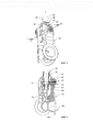
На фиг. 4-7 показан верхний осевой конец держателя 30 рабочих элементов узла 29 мешалки с тремя различными вариантами осуществления соединительных устройств 67, 68 и 69, которые в различных гнездах 70, 71, 72 содержат соответствующее стопорное кольцо 73. На фиг. 4 и 6 показаны соединительные устройства 67 и 68 в транспортном положении узла 29 мешалки. На фиг. 5 в частичном разрезе наглядно показано соединительное устройство 68, которое служит для соединения держателя 30 рабочих элементов узла 29 мешалки с крышкой 28. При этом держатель 30 рабочих элементов, показанный на фиг. 5 и 6, содержит гнездо 71, выполненное в виде втулки, приваренной к верхнему осевому концу держателя 30 рабочих элементов. При сборке верхний осевой конец держателя 30 рабочих элементов с присоединенным к нему гнездом 71 вводится снизу через образованное в крышке 28 проходное отверстие 74, после чего стопорное кольцо 73 вводится сверху в гнездо 76, предусмотренное в крышке для установки заглушки 75, и может быть закреплено в гнезде 71, которое содержит паз 78, ограниченный двумя буртиками 77. В результате обеспечивается относительное позиционирование между крышкой 28 и соединительным устройством 68, при котором стопорное кольцо 73 прилегает к опорной кромке 79, которая ограничивает проходное отверстие в основании крышки 28, при этом стопорное кольцо 73 образует осевой упор для опорной кромки 79.FIG. 4-7 show the upper axial end of the
Если после этого сверху в гнездо 76 для заглушки крышки 28 завинчивается заглушка 75, то нижняя кромка 80 заглушки 75 вместе с опорной кромкой 79 крышки 28 ограничивает полость 81 для стопорного кольца, в котором стопорное кольцо в любом случае может иметь лишь ограниченное осевое перемещение или, по существу, не иметь осевого перемещения, при этом обеспечивается надежное соединение между крышкой 28 и держателем 30 рабочих элементов.If then a
Таким образом, контейнер 20 можно также комбинировать с узлом 29 мешалки независимо от установки мешалки. Если требуется соединить мешалку с узлом 29 мешалки, чтобы перемешивать находящуюся в контейнере жидкость, достаточно извлечь заглушку 75 из гнезда 76 в крышке 28, ввести сверху вал 38 мешалки в держатель 30 рабочих элементов и соединить с ним. При этом мешалка может быть обычным образом установлена на контейнере 20 или на опорной конструкции, соединенной с кожухом контейнера 20, и присоединена к ней. Это предпочтительно осуществляется при помощи небольшого осевого подъема держателя 30 рабочих элементов из контейнера 20, как, например, показано на фиг. 3, чтобы предотвратить физический контакт между стопорным кольцом 73 и опорной кромкой 79 крышки 28, в то время, когда держатель 30 рабочих элементов приводится во вращение валом 38 мешалки, и, таким образом, по возможности, исключить износ контакта, загрязняющий жидкость.Thus, the
Claims (40)
Applications Claiming Priority (5)
| Application Number | Priority Date | Filing Date | Title |
|---|---|---|---|
| DE102015204394.0 | 2015-03-11 | ||
| DE102015204394 | 2015-03-11 | ||
| DE102015210904.6A DE102015210904B4 (en) | 2015-03-11 | 2015-06-15 | Stirring bar arrangement and transport and storage containers for liquids with a stirring bar arrangement |
| DE102015210904.6 | 2015-06-15 | ||
| PCT/EP2016/051497 WO2016142090A2 (en) | 2015-03-11 | 2016-01-26 | Stirring rod assembly and transport and storage container for liquids with a stirring rod assembly |
Publications (3)
| Publication Number | Publication Date |
|---|---|
| RU2017131897A3 RU2017131897A3 (en) | 2019-04-11 |
| RU2017131897A RU2017131897A (en) | 2019-04-11 |
| RU2690341C2 true RU2690341C2 (en) | 2019-05-31 |
Family
ID=56801093
Family Applications (1)
| Application Number | Title | Priority Date | Filing Date |
|---|---|---|---|
| RU2017131897A RU2690341C2 (en) | 2015-03-11 | 2016-01-26 | Agitator assembly and container for transportation and storage of liquids, equipped with such unit of mixer |
Country Status (23)
| Country | Link |
|---|---|
| US (1) | US10561998B2 (en) |
| EP (2) | EP3369477B1 (en) |
| JP (1) | JP6412662B2 (en) |
| KR (1) | KR101946939B1 (en) |
| CN (2) | CN107405585B (en) |
| AR (1) | AR103770A1 (en) |
| AU (1) | AU2016228371B2 (en) |
| BR (1) | BR112017019160B1 (en) |
| CA (1) | CA2977717C (en) |
| CL (1) | CL2017002231A1 (en) |
| CO (1) | CO2017009896A2 (en) |
| DE (1) | DE102015210904B4 (en) |
| DK (2) | DK3268121T3 (en) |
| ES (2) | ES2896798T3 (en) |
| IL (1) | IL254135B (en) |
| MX (1) | MX2017011114A (en) |
| MY (1) | MY188721A (en) |
| PL (2) | PL3369477T3 (en) |
| RU (1) | RU2690341C2 (en) |
| SA (1) | SA517382275B1 (en) |
| SG (1) | SG11201707062WA (en) |
| WO (1) | WO2016142090A2 (en) |
| ZA (1) | ZA201706128B (en) |
Families Citing this family (3)
| Publication number | Priority date | Publication date | Assignee | Title |
|---|---|---|---|---|
| DE102015210904B4 (en) | 2015-03-11 | 2018-03-15 | Protechna S.A. | Stirring bar arrangement and transport and storage containers for liquids with a stirring bar arrangement |
| DE102015011967A1 (en) | 2015-09-18 | 2017-03-23 | Protechna S.A. | Stirring device, stirring bar arrangement and transport and storage containers for liquids with a stirring bar arrangement |
| CN113856530B (en) * | 2021-12-02 | 2022-02-18 | 山东金宜善新材料有限公司 | A stirred tank for preparing tetrabromobisphenol A |
Citations (8)
| Publication number | Priority date | Publication date | Assignee | Title |
|---|---|---|---|---|
| US1898094A (en) * | 1931-04-27 | 1933-02-21 | Frederick H Nies | Amalgam mixer or the like |
| DE2420605A1 (en) * | 1974-04-27 | 1975-11-06 | Hoess Walter | Liquid manure stirring mechanism - has stirring blades at bottom of motor driven shaft supported in joints |
| SU1152639A1 (en) * | 1982-12-09 | 1985-04-30 | Chernyavskij Valentin L | Apparatus for mixing liquids |
| SU1662658A1 (en) * | 1989-03-31 | 1991-07-15 | Предприятие П/Я А-1229 | Paint mixer |
| JP3210877B2 (en) * | 1997-02-28 | 2001-09-25 | 中国塗料株式会社 | Stirrer and tank with stirrer |
| CA2644168A1 (en) * | 2008-11-18 | 2010-05-18 | 1350363 Alberta Ltd. | Agitator tool for progressive cavity pump |
| DE102011051499A1 (en) * | 2011-07-01 | 2013-01-03 | Turbo-Misch- und Rühranlagen GmbH & Co. KG | Shaft sealing arrangement for use in agitator and container arrangement for sealing opening of container and for sealing passage of shaft of agitator received in opening of container, has sealing carrier provided with sealing section |
| EP2620210A1 (en) * | 2012-01-24 | 2013-07-31 | SPX Corporation | Impeller device and system |
Family Cites Families (29)
| Publication number | Priority date | Publication date | Assignee | Title |
|---|---|---|---|---|
| GB115933A (en) * | 1917-06-19 | 1918-05-30 | Richard Ames | Improvements in and connected with Apparatus for Aerating Sewage and other Foul Liquids. |
| US3381941A (en) * | 1966-08-17 | 1968-05-07 | Fmc Corp | Stirring apparatus |
| SU1162658A1 (en) * | 1982-04-23 | 1985-06-23 | Всесоюзный научно-исследовательский институт строительного и дорожного машиностроения | Vehicle steering system |
| CH666628A5 (en) * | 1984-03-12 | 1988-08-15 | Arnold Ag | AGITATOR IN A STORAGE CONTAINER FOR SUSPENDING SOLIDS AND LIQUIDS. |
| JPS61143631A (en) | 1984-12-17 | 1986-07-01 | Toshiba Corp | Cooker |
| JPS61143631U (en) * | 1985-02-28 | 1986-09-04 | ||
| CH675215A5 (en) | 1988-02-08 | 1990-09-14 | Kurt Walter Wyss | |
| DE19749223A1 (en) | 1997-11-07 | 1999-05-20 | Thomas Beindorf | Mixer assembly for use waste water treatment or paper processing industry |
| JP2000262879A (en) * | 1999-03-15 | 2000-09-26 | Fujio Tomota | Stirrer for use in to stirring in container |
| ATE355122T1 (en) * | 2001-06-25 | 2006-03-15 | Japan Techno Co Ltd | OSCILLATING MIXER AND PROCESSING APPARATUS AND METHOD FOR USING THE SAME |
| US20040145965A1 (en) * | 2003-01-29 | 2004-07-29 | Chiaphua Industries Limited | Mixing cooker |
| JP4359473B2 (en) | 2003-09-26 | 2009-11-04 | 株式会社愛工舎製作所 | Stirrer and stirrer with stirrer |
| US7441940B2 (en) | 2003-10-23 | 2008-10-28 | Sport Usa, Llc | Collapsible mixing wand |
| EP1763575A4 (en) * | 2004-04-27 | 2009-09-23 | Baxter Int | Stirred-tank reactor system |
| DE102005003528A1 (en) * | 2005-01-25 | 2006-07-27 | Wp-Aro Gmbh | Stirring arrangement for mixing media has nozzle longitudinal axis of two stirring nozzles tilted about tilting angle opposite its axis of rotation |
| US7682067B2 (en) * | 2005-04-22 | 2010-03-23 | Hyclone Laboratories, Inc. | Mixing systems and related mixers |
| DE102008063393B3 (en) * | 2008-12-30 | 2010-06-02 | Martin Hirzel | Bördelrührer |
| CN102019162A (en) * | 2009-09-11 | 2011-04-20 | 王曦 | Device for increasing working efficiency of reaction device |
| DE202010003501U1 (en) * | 2010-03-11 | 2010-05-27 | Mape Distribution & Logistik Gmbh | Quirling head and whirling device with whisk head |
| DE102010060094B4 (en) * | 2010-06-18 | 2015-10-01 | Leifheit Ag | Active ingredient for food processing equipment |
| JP5084981B1 (en) * | 2011-12-27 | 2012-11-28 | 中国塗料株式会社 | Stirrer |
| US9101887B2 (en) * | 2012-01-24 | 2015-08-11 | Spx Flow | Mixer attachment assembly apparatus and method |
| CN102989358A (en) * | 2012-12-04 | 2013-03-27 | 江西稀有稀土金属钨业集团有限公司 | Agitator with variable diameter |
| CN203556307U (en) * | 2013-09-18 | 2014-04-23 | 安徽美诺新材料科技有限公司 | Dispersion force-adjustable vertical disperser |
| CN203555643U (en) * | 2013-11-08 | 2014-04-23 | 青岛埠元电子有限公司 | Pulverizing cup |
| CN203990493U (en) * | 2014-07-30 | 2014-12-10 | 哈尔滨圣泰生物制药有限公司 | Electric stirring oar for biochemical workshop |
| CN204122061U (en) * | 2014-09-05 | 2015-01-28 | 天津冶金职业技术学院 | A kind of metallurgical laboratory Melt Stirring device |
| DE102015210904B4 (en) | 2015-03-11 | 2018-03-15 | Protechna S.A. | Stirring bar arrangement and transport and storage containers for liquids with a stirring bar arrangement |
| TWM532357U (en) | 2016-07-22 | 2016-11-21 | Easyway Automation Co Ltd | Five-axes gantry robotic manipulator |
-
2015
- 2015-06-15 DE DE102015210904.6A patent/DE102015210904B4/en not_active Expired - Fee Related
-
2016
- 2016-01-26 MY MYPI2017703269A patent/MY188721A/en unknown
- 2016-01-26 EP EP18167888.9A patent/EP3369477B1/en active Active
- 2016-01-26 SG SG11201707062WA patent/SG11201707062WA/en unknown
- 2016-01-26 ES ES18167888T patent/ES2896798T3/en active Active
- 2016-01-26 ES ES16703736T patent/ES2765867T3/en active Active
- 2016-01-26 CA CA2977717A patent/CA2977717C/en active Active
- 2016-01-26 JP JP2017547147A patent/JP6412662B2/en active Active
- 2016-01-26 BR BR112017019160-1A patent/BR112017019160B1/en active IP Right Grant
- 2016-01-26 MX MX2017011114A patent/MX2017011114A/en active IP Right Grant
- 2016-01-26 RU RU2017131897A patent/RU2690341C2/en active
- 2016-01-26 AU AU2016228371A patent/AU2016228371B2/en active Active
- 2016-01-26 PL PL18167888T patent/PL3369477T3/en unknown
- 2016-01-26 KR KR1020177025238A patent/KR101946939B1/en active IP Right Grant
- 2016-01-26 PL PL16703736T patent/PL3268121T3/en unknown
- 2016-01-26 EP EP16703736.5A patent/EP3268121B1/en active Active
- 2016-01-26 WO PCT/EP2016/051497 patent/WO2016142090A2/en active Application Filing
- 2016-01-26 CN CN201680015028.XA patent/CN107405585B/en active Active
- 2016-01-26 DK DK16703736T patent/DK3268121T3/en active
- 2016-01-26 DK DK18167888.9T patent/DK3369477T3/en active
- 2016-01-26 US US15/556,000 patent/US10561998B2/en active Active
- 2016-02-25 AR ARP160100485A patent/AR103770A1/en active IP Right Grant
- 2016-03-02 CN CN201620159163.9U patent/CN205797138U/en active Active
-
2017
- 2017-08-24 IL IL254135A patent/IL254135B/en active IP Right Grant
- 2017-09-04 CL CL2017002231A patent/CL2017002231A1/en unknown
- 2017-09-08 ZA ZA2017/06128A patent/ZA201706128B/en unknown
- 2017-09-11 SA SA517382275A patent/SA517382275B1/en unknown
- 2017-09-27 CO CONC2017/0009896A patent/CO2017009896A2/en unknown
Patent Citations (8)
| Publication number | Priority date | Publication date | Assignee | Title |
|---|---|---|---|---|
| US1898094A (en) * | 1931-04-27 | 1933-02-21 | Frederick H Nies | Amalgam mixer or the like |
| DE2420605A1 (en) * | 1974-04-27 | 1975-11-06 | Hoess Walter | Liquid manure stirring mechanism - has stirring blades at bottom of motor driven shaft supported in joints |
| SU1152639A1 (en) * | 1982-12-09 | 1985-04-30 | Chernyavskij Valentin L | Apparatus for mixing liquids |
| SU1662658A1 (en) * | 1989-03-31 | 1991-07-15 | Предприятие П/Я А-1229 | Paint mixer |
| JP3210877B2 (en) * | 1997-02-28 | 2001-09-25 | 中国塗料株式会社 | Stirrer and tank with stirrer |
| CA2644168A1 (en) * | 2008-11-18 | 2010-05-18 | 1350363 Alberta Ltd. | Agitator tool for progressive cavity pump |
| DE102011051499A1 (en) * | 2011-07-01 | 2013-01-03 | Turbo-Misch- und Rühranlagen GmbH & Co. KG | Shaft sealing arrangement for use in agitator and container arrangement for sealing opening of container and for sealing passage of shaft of agitator received in opening of container, has sealing carrier provided with sealing section |
| EP2620210A1 (en) * | 2012-01-24 | 2013-07-31 | SPX Corporation | Impeller device and system |
Also Published As
Similar Documents
| Publication | Publication Date | Title |
|---|---|---|
| JP6674017B2 (en) | Stirring member, stirring bar assembly, and transport storage container for liquid including stirring bar assembly | |
| RU2690341C2 (en) | Agitator assembly and container for transportation and storage of liquids, equipped with such unit of mixer | |
| CN100467133C (en) | Disposable centrifuge rotor | |
| US10022685B2 (en) | Mixing device for mixing liquids in a mixing tank | |
| KR980010664A (en) | Toner cartridge with stirrer and stirrer | |
| US9327256B2 (en) | Impeller assembly apparatus and method | |
| US9101887B2 (en) | Mixer attachment assembly apparatus and method | |
| CN112569819A (en) | Stirrer and stirring device | |
| CN214416088U (en) | Stirrer and stirring device | |
| US10045664B2 (en) | Blade assembly with safety guard | |
| BE1022904B1 (en) | ROTOR STATOR MIXER | |
| US20160038895A1 (en) | Self supporting in-container mix/blend system | |
| US20210394137A1 (en) | Stirrer assembly | |
| RU2596967C2 (en) | Device for food product preparation | |
| KR101988435B1 (en) | Blade Auto assembling apparatus of torque converter | |
| JP6426501B2 (en) | Toner cartridge and image forming apparatus | |
| JP2003154250A (en) | Vertical agitation apparatus |