RU2630904C2 - Device for transplanting plants - Google Patents
Device for transplanting plants Download PDFInfo
- Publication number
- RU2630904C2 RU2630904C2 RU2014143801A RU2014143801A RU2630904C2 RU 2630904 C2 RU2630904 C2 RU 2630904C2 RU 2014143801 A RU2014143801 A RU 2014143801A RU 2014143801 A RU2014143801 A RU 2014143801A RU 2630904 C2 RU2630904 C2 RU 2630904C2
- Authority
- RU
- Russia
- Prior art keywords
- plant
- furrow
- soil
- keel
- transfer
- Prior art date
Links
Images


Classifications
-
- A—HUMAN NECESSITIES
- A01—AGRICULTURE; FORESTRY; ANIMAL HUSBANDRY; HUNTING; TRAPPING; FISHING
- A01C—PLANTING; SOWING; FERTILISING
- A01C11/00—Transplanting machines
- A01C11/02—Transplanting machines for seedlings
-
- A—HUMAN NECESSITIES
- A01—AGRICULTURE; FORESTRY; ANIMAL HUSBANDRY; HUNTING; TRAPPING; FISHING
- A01C—PLANTING; SOWING; FERTILISING
- A01C11/00—Transplanting machines
-
- A—HUMAN NECESSITIES
- A01—AGRICULTURE; FORESTRY; ANIMAL HUSBANDRY; HUNTING; TRAPPING; FISHING
- A01C—PLANTING; SOWING; FERTILISING
- A01C11/00—Transplanting machines
- A01C11/02—Transplanting machines for seedlings
- A01C11/025—Transplanting machines using seedling trays; Devices for removing the seedlings from the trays
-
- A—HUMAN NECESSITIES
- A01—AGRICULTURE; FORESTRY; ANIMAL HUSBANDRY; HUNTING; TRAPPING; FISHING
- A01C—PLANTING; SOWING; FERTILISING
- A01C5/00—Making or covering furrows or holes for sowing, planting or manuring
- A01C5/04—Machines for making or covering holes for sowing or planting
Abstract
Description
Перекрестные ссылки на родственные заявкиCross references to related applications
[001] Данная заявка является родственной по отношению к приоритетной заявке на патент Дании № РА 2013 70660 ''AN APPARATUS FOR TRANSPLANTING PLANTS'', зарегистрированной 8 ноября 2013 года, и предварительной заявке на патент США 62/021042 ''AN APPARATUS FOR TRANSPLANTING PLANTS'', зарегистрированной 4 июля 2014 года.[001] This application is related to priority Danish patent application No. RA 2013 70660 '' AN APPARATUS FOR TRANSPLANTING PLANTS '', filed November 8, 2013, and provisional patent application US 62/021042 '' AN APPARATUS FOR TRANSPLANTING PLANTS '', registered July 4, 2014.
Область техникиTechnical field
[002] Данное раскрытие направлено на устройство и способ для пересаживания растений, содержащие модуль пересаживания, конфигурация которого приспособлена для пересаживания множества растений в ряд.[002] This disclosure is directed to a device and method for replanting plants containing a replanting module, the configuration of which is adapted for replanting multiple plants in a row.
Предпосылки к созданию изобретенияBACKGROUND OF THE INVENTION
[003] Пересаживание растений и/или саженцев из теплицы, рассадника или других мест выращивания в грунт часто является операцией, которую производят, чтобы повысить урожайность. Преимущества пересаживания растений/саженцев в поле или в почву можно усматривать в продлении вегетационного периода благодаря тому, что растения начинают выращивать в помещении до того, как внешние условия станут благоприятными. При высаживании саженцев, в отличие от прямого посева, можно защищать молодые растения от болезней и вредителей и избегать проблем с прорастанием.[003] Transplanting plants and / or seedlings from a greenhouse, nursery or other cultivation site into the ground is often an operation that is performed to increase yield. The advantages of transplanting plants / seedlings in the field or in the soil can be seen in the extension of the growing season due to the fact that the plants begin to grow indoors before the external conditions become favorable. When planting seedlings, in contrast to direct sowing, you can protect young plants from diseases and pests and avoid problems with germination.
[004] К операции ручного пересаживания прибегали долгое время, и она может рассматриваться как процесс, требующий очень больших затрат времени, поскольку растения приходится высаживать в почву руками и на каждое пересаживание уходит очень много времени. Поэтому в профессиональном сельском хозяйстве операции пересаживания часто выполняются устройствами, которые способны подготавливать почву, а также помогать в помещении растений в правильные положения. Такие пересадочные машины можно видеть на примере вращающейся пересадочной машины, в которой устройство подготавливает грунт одним рядом, а саженцы или растения вручную вводятся во вращающуюся обойму, так чтобы устройство могло поместить растения в почву, прежде чем вводить в грунт следующее растение.[004] A manual transplant operation has been resorted to for a long time, and it can be considered as a very time consuming process, since the plants have to be planted in the soil by hand and each transplant takes a lot of time. Therefore, in professional agriculture, transplantation operations are often performed by devices that are capable of preparing the soil, as well as helping to put the plants in the correct positions. Such transplanting machines can be seen in the example of a rotating transplanting machine in which the device prepares the soil in one row, and seedlings or plants are manually inserted into the rotating holder so that the device can place the plants in the soil before introducing the next plant into the soil.
[005] Проблема полуавтоматических однорядных пересадочных машин состоит в том, что пересаживать целое поле сельскохозяйственной культуры очень долго, поскольку скорость пересадки зависит от скорости оператора и за раз можно обработать только один ряд. Таким образом, существует потребность в более быстром способе пересаживания саженцев/растений.[005] The problem with semi-automatic single-row transfer machines is that it takes a long time to transplant an entire field of agricultural crops, since the transfer speed depends on the speed of the operator and only one row can be processed at a time. Thus, there is a need for a faster method of replanting seedlings / plants.
[006] В AU 2007100035 предлагается устройство пересаживания для высокоплотной высадки саженцев во в целом плоскую, гладкую грядку в несколько рядов, где каждый ряд обеспечивается трубкой для подвода саженцев, лопастями, которые проходят латерально под пластиной скольжения для вырезания борозды для каждого ряда, и содержит средства удерживания и выгрузки саженца, который подается из подающей трубки в положение для высадки в борозду. Это устройство способно пересаживать больше саженцев за раз, то есть большее количество саженцев вводится в грунт в поперечном направлении.[006] AU 2007100035 proposes a transplanting device for high-density planting of seedlings in a generally flat, smooth bed in several rows, where each row is provided with a tube for supplying seedlings, with blades that extend laterally under the slide plate to cut a furrow for each row, and contains means for holding and unloading the seedling, which is fed from the feed tube to the landing position in the furrow. This device is able to transplant more seedlings at a time, that is, a larger number of seedlings are introduced into the soil in the transverse direction.
[007] Однако проблема такого устройства состоит в том, что скорость введения саженцев в направлении высаживания, т.е. вдоль ряда, ограничена из-за механических ограничений, поскольку лопасти нельзя протаскивать по грунту на большой скорости из-за мощных сил и воздействий, которые окажет на лопасти грунт. Более того борозды вырезаются в грунте клиновидными лопастями, а это означает, что материал, удаляемый из вырезаемых борозд, должен выводиться из борозды, из-за чего на лопасти ложится большая механическая нагрузка.[007] However, the problem with such a device is that the rate of introduction of seedlings in the direction of planting, i.e. along the row, it is limited due to mechanical limitations, since the blades cannot be dragged along the ground at high speed due to the powerful forces and influences that the soil will have on the blades. Moreover, the furrows are cut out in the soil by wedge-shaped blades, which means that the material removed from the cut furrows must be removed from the furrow, which imposes a large mechanical load on the blades.
[008] Следовательно, существует потребность в устройстве пересаживания, которое способно пересаживать саженец в грунт с большой скоростью при высокой стабильности, чтобы минимизировать количество времени, затрачиваемого на каждый саженец в ряду, так чтобы оптимизировалась эффективность операции пересаживания. Стабильность операции пересаживания означает, что можно оптимизировать использование почвы поля для выращивания растений, чтобы обеспечить, чтобы у каждого растения имелась нужная площадь почвы, чтобы расти эффективным образом.[008] Therefore, there is a need for a transplant device that is capable of transplanting a seedling into the soil at high speed with high stability in order to minimize the amount of time spent on each seedling in a row so that the efficiency of the transplanting operation is optimized. The stability of the transplant operation means that it is possible to optimize the use of the soil of the field for growing plants to ensure that each plant has the right soil area in order to grow in an efficient manner.
Краткое изложение сущности изобретенияSummary of the invention
[009] Согласно изобретению, обеспечивается устройство для пересаживания растений, содержащее модуль пересаживания, конфигурация которого приспособлена для пересаживания множества растений в ряд, причем модуль пересаживания содержит: поверхность контакта с почвой (пластину скольжения), которая в целом лежит в одной плоскости с отведенной под посадку почвой, килевой элемент, чтобы создавать борозду в почве, где киль проходит на заданное расстояние под поверхностью контакта с почвой, где внешняя периферия килевого элемента определяет глубину борозды, средство переноса, конфигурация которого приспособлена для поддерживания растения, где средство переноса проходит от положения над поверхностью контакта с почвой к положению под поверхностью контакта с почвой, и проходит на заданную глубину в борозду для перемещения растения из устройства в борозду, где средство переноса содержит дальний конец для выгрузки растения и где конфигурация средства переноса приспособлена для воздействия на внешнюю периферию растения под поверхностью контакта с почвой, так чтобы, по меньшей мере, одна боковая стенка борозды приходила в соприкосновение с внешней периферией растения перед выгрузкой растения из дальнего конца средства переноса, средство перемещения для поддерживания и перемещения растения при помощи средства переноса в борозду по продольной оси, которая в целом параллельна направлению высаживания устройства, где конфигурация средства перемещения приспособлена для высвобождения растения, когда растение достигает заданной глубины в борозде.[009] According to the invention, there is provided a device for replanting plants comprising a replanting module, the configuration of which is adapted for replanting a plurality of plants in a row, wherein the replanting module comprises: a contact surface with soil (a sliding plate), which generally lies in the same plane as planting with soil, keel element, to create a furrow in the soil, where the keel passes a predetermined distance below the surface of contact with the soil, where the outer periphery of the keel element determines the depth well, a furrow, a means of transfer, the configuration of which is adapted to support the plant, where the means of transfer passes from a position above the surface of contact with the soil to a position below the surface of contact with the soil, and passes to a predetermined depth in the furrow to move the plant from the device to the furrow, where the means of transfer contains a distal end for unloading the plant and where the configuration of the transfer means is adapted to act on the outer periphery of the plant under the surface of contact with the soil, so that at least , one side wall of the furrow came into contact with the outer periphery of the plant before unloading the plant from the far end of the transfer means, a transfer means for supporting and moving the plant with the transfer means into the furrow along the longitudinal axis, which is generally parallel to the planting direction of the device, where the configuration of the transfer means adapted to release the plant when the plant reaches a predetermined depth in the furrow.
[0010] Согласно изобретению, килевой элемент и средство переноса могут быть отдельными частями/элементами, которые способны выполнять задачи частей/элементов. Альтернативно, эти части/элементы представлены цельно в виде единого элемента, который способен выполнять все аспекты этих частей/элементов.[0010] According to the invention, the keel element and the transfer means may be separate parts / elements that are capable of performing the tasks of the parts / elements. Alternatively, these parts / elements are presented integrally as a single element that is able to fulfill all aspects of these parts / elements.
[0011] Устройство согласно изобретению способно пересаживать растения с большой скоростью и очень четко выдерживать расстояние между каждым пересаживаемым растением/саженцем. Устройство может быть прикреплено к транспортному средству, такому как трактор, которое способно доставлять устройство на место пересадки или поле. Альтернативно, устройство может быть самоходным, т.е. содержать необходимые механические компоненты, чтобы передвигаться самостоятельно, или же устройство может быть неотделимой частью пересаживающего транспортного средства. Перед началом пересаживания устройство может опускаться в направлении грунта или почвы, так чтобы поверхность контакта с почвой могла приходить в соприкосновение с поверхностью почвы.[0011] The device according to the invention is able to transplant plants at high speed and very accurately withstand the distance between each transplanted plant / seedling. The device may be attached to a vehicle, such as a tractor, that is capable of delivering the device to a transplant site or field. Alternatively, the device may be self-propelled, i.e. contain the necessary mechanical components to move independently, or the device may be an integral part of the transplanting vehicle. Before transplanting, the device can lower in the direction of the soil or soil, so that the contact surface with the soil can come in contact with the surface of the soil.
[0012] Когда устройство переведено/опущено в такое положение, чтобы начать операцию пересаживания, транспортное средство может перемещать устройство в направлении пересаживания, т.е. в направлении ряда, отведенного под пересаживание. Поверхность контакта с почвой обеспечивает, чтобы устройство находилось в правильном вертикальном положении относительно поверхности почвы, обеспечивая, чтобы килевой элемент и/или средство переноса проходили на заданную глубину в грунт/почву, создавая борозду желательной глубины, и обеспечивая, чтобы растение вводилось в борозду на определенную глубину. Поверхность контакта с почвой может помогать в уплотнении почвы, так чтобы было легче создавать борозду, и может также помогать контролировать глубину высаживания, обеспечивая, чтобы устройство не проваливалось в почву. Поверхность контакта с почвой может иметь вид пластины скольжения, лыж, колес или поверхности любого типа, которая способна контролировать глубину проникновения устройства.[0012] When the device is moved / lowered in such a position as to initiate the transplant operation, the vehicle can move the device in the transplant direction, i.e. in the direction of the row reserved for transplantation. The contact surface with the soil ensures that the device is in the correct vertical position relative to the soil surface, ensuring that the keel element and / or transfer means extend to a predetermined depth in the soil / soil, creating a furrow of the desired depth, and ensuring that the plant is introduced into the furrow on a certain depth. The soil contact surface can help in compaction of the soil, so that it is easier to create a furrow, and can also help control the depth of planting, ensuring that the device does not fall into the soil. The contact surface with the soil may take the form of a sliding plate, ski, wheel or any type of surface that is capable of controlling the depth of penetration of the device.
[0013] Килевой элемент проходит от поверхности контакта с почвой в вертикальном направлении вниз в грунт, позволяя устройству проникать в почву во время операции высаживания, и, когда его перемещают в направлении высаживания, создает борозду, которая проходит в том же направлении, что и направление высаживания устройства/транспортного средства. Киль может содержать внешнюю периферию, которая может определять низшую точку устройства, и где внешняя периферия определяет глубину борозды, подлежащей созданию. Это означает, что внешняя периферия киля создает, по меньшей мере, дно (низшую часть) борозды. Киль обеспечивает, чтобы борозда содержала боковые стенки и дно, где во время операции пересаживания киль оставляет, по меньшей мере, части борозды открытыми, по меньшей мере, пока растение не будет правильно введено в борозду. Таким образом, килевой элемент может также выполнять функцию опорного элемента для борозды, обеспечивая, чтобы борозда не засыпалась до введения растения.[0013] The keel element extends from the soil contact surface in a vertical direction down to the ground, allowing the device to penetrate the soil during the planting operation, and when it is moved in the planting direction, creates a furrow that extends in the same direction as the direction planting device / vehicle. The keel may comprise an outer periphery that can define the lowest point of the device, and where the outer periphery determines the depth of the furrow to be created. This means that the outer periphery of the keel creates at least the bottom (lower part) of the furrow. The keel ensures that the furrow contains the side walls and the bottom, where during the transplantation operation the keel leaves at least part of the furrow open, at least until the plant is correctly inserted into the furrow. Thus, the keel element can also serve as a support element for the furrow, ensuring that the furrow does not fall asleep before the introduction of the plant.
[0014] Ширина борозды может контролироваться поперечной шириной килевого элемента, так что поперечная периферия килевого элемента может примыкать к боковой стенке борозды во время операции пересаживания, тем самым обеспечивая, чтобы почва выталкивалась из пространства, освобождаемого килевым элементом, который определяет борозду, где материал может выталкиваться либо вперед, либо в стороны.[0014] The width of the furrow can be controlled by the transverse width of the keel element, so that the transverse periphery of the keel element can abut against the side wall of the furrow during the transplanting operation, thereby ensuring that the soil is pushed out of the space released by the keel element, which defines the furrow, where the material can pushed either forward or sideways.
[0015] В устройство можно загружать множество растений, которые могут вводиться, например, в виде лотка или ленты саженцев, где каждое растение вводится в средство переноса. Средство переноса может быть способно переносить множество растений, где растения выстроены в ряд, один за другим, подобно тому, как работает обойма или конвейерная лента. Средство перемещения может быть приспособлено захватывать растение, когда растение находится внутри устройства, и где средство перемещения приспособлено передавать растение из устройства по средству переноса в борозду.[0015] A plurality of plants can be loaded into the device, which can be introduced, for example, in the form of a tray or tape of seedlings, where each plant is introduced into the transfer medium. The transfer medium may be capable of transferring a plurality of plants where plants are arranged in a row, one after another, similar to how a clip or conveyor belt works. The transfer means may be adapted to capture the plant when the plant is inside the device, and where the transfer means is adapted to transfer the plant from the device via the transfer means to the furrow.
[0016] Средство перемещения вводит растение в борозду в направлении, которое параллельно борозде, так чтобы растение ''соскальзывало'' в борозду. Сочетание использования средства переноса для поддерживания растения и средства перемещения, чтобы передавать растение, обеспечивает то, чтобы растение высвобождалось только в правильный момент, так чтобы обеспечивалось, что растение проходит на заданную глубину под поверхностью почвы. Заданная глубина под поверхностью почвы может выбираться исходя из типа предназначенного для посадки растения и может регулироваться для каждого типа растения.[0016] The moving means introduces the plant into the furrow in a direction that is parallel to the furrow so that the plant “slides” into the furrow. The combination of using a transfer means to support the plant and a transfer means to transmit the plant ensures that the plant is released only at the right moment, so that the plant passes to a predetermined depth below the surface of the soil. The predetermined depth below the soil surface can be selected based on the type of plant intended for planting and can be adjusted for each type of plant.
[0017] Когда растение достигает своего низшего положения, боковая стенка борозды охватывает стороны растения, так чтобы устанавливалась ориентация и глубина растения. Таким образом, растение фиксируется в почве, и движение растения относительно устройства контролируется движением устройства относительно почвы, и нет необходимости поддерживать растение. Таким образом, движение устройства будет обеспечивать, чтобы устройство отводилось от растения.[0017] When the plant reaches its lowest position, the side wall of the furrow covers the sides of the plant so that the orientation and depth of the plant are established. Thus, the plant is fixed in the soil, and the movement of the plant relative to the device is controlled by the movement of the device relative to the soil, and there is no need to maintain the plant. Thus, the movement of the device will ensure that the device is diverted from the plant.
[0018] Далее следующее растение вводится в борозду в другом продольном положении, отличном от предыдущего растения, и высаживается устройством, как описано выше.[0018] Next, the next plant is introduced into the furrow in a different longitudinal position, different from the previous plant, and planted by the device, as described above.
[0019] В одном варианте осуществления средство перемещения высвобождает растение, после того как дальняя часть растения проходит дальний конец средства переноса. Это означает, что растение прошло дальний конец и больше не поддерживается или только частично поддерживается средством переноса.[0019] In one embodiment, the transfer means releases the plant after the far part of the plant passes the far end of the transfer means. This means that the plant has passed the far end and is no longer supported or only partially supported by the vehicle.
[0020] В некоторых вариантах осуществления средство перемещения зафиксировано. Термин ''зафиксирован'' означает, что толкатели не гнутся ни в какой точке по длине рычага.[0020] In some embodiments, the moving means is fixed. The term “locked” means that the pushers do not bend at any point along the length of the lever.
[0021] В варианте осуществления средство перемещения является отводным. Термин ''отводной'' при использовании в отношении толкателей означает, что по длине рычага, например, между главным рычагом (52) и нижним рычагом (53), существует, по меньшей мере, одна точка вращения, как показано на фигуре 5А.[0021] In an embodiment, the moving means is a retractable means. The term “retractable” when used with respect to pushers means that along the length of the lever, for example, between the main lever (52) and the lower lever (53), there is at least one pivot point, as shown in Figure 5A.
[0022] Отвод средства перемещения позволяет регулировать расстояние между пересаживаемыми растениями и также при высокой скорости пересаживания (т.е. трактор может ехать с более высокой скоростью). При использовании отводного средства перемещения может достигаться более высокая плотность пересаживаемых растений на участок земли. Кроме того, отводные перемещающие элементы делают возможным более быстрое засаживание единицы земли. В одном варианте осуществления расстояние между пересаживаемыми растениями может варьироваться от 10 сантиметров до 24 сантиметров в ряду. Расстояние может составлять от 8 сантиметров до 65 сантиметров, от 4 дюймов до 24 дюймов. Расстояние между растениями постоянно и не меняется во время высаживания.[0022] The removal of the means of movement allows you to adjust the distance between transplanted plants and also at a high speed of transplantation (ie, the tractor can drive at a higher speed). When using a bypass means of movement, a higher density of transplanted plants on a plot of land can be achieved. In addition, tap-off moving elements make it possible to plant a unit of land faster. In one embodiment, the distance between transplanted plants can vary from 10 centimeters to 24 centimeters in a row. The distance can range from 8 centimeters to 65 centimeters, from 4 inches to 24 inches. The distance between plants is constant and does not change during planting.
[0023] Когда используется множество модулей, растения могут высаживаться в виде параллельных рядов или смещенных рядов. Как известно специалистам в области техники, при смещенной конфигурации растения высаживаются относительно соседнего ряда так, чтобы образовывать форму ромба. Это позволяет достигать более высокой плотности растений на единицу земли. Соседние модули регулируются, чтобы обеспечивать это смещение, путем независимой установки времени, когда толкатели погружают растение в почву.[0023] When multiple modules are used, plants can be planted in parallel rows or offset rows. As is known to those skilled in the art, when the configuration is shifted, the plants are planted relative to the adjacent row so as to form a diamond shape. This allows you to achieve a higher density of plants per unit of land. Adjacent modules are adjusted to provide this bias, by independently setting the time when the pushers immerse the plant in the soil.
[0024] В одном варианте осуществления изобретения устройство может дополнительно содержать уплотнитель, чтобы уплотнять почву, которая отведена под посадку. Некоторые типы почвы могут быть относительно рыхлыми, особенно если почва сухая, и может возникнуть необходимость уплотнить почву перед тем, как вводить киль в грунт, чтобы создать борозду. В некоторых ситуациях почва может быть настолько рыхлой, что киль сам по себе не создаст четко определенной борозды, поскольку боковые стенки могут крошиться, осыпаться или распадаться из-за такой рыхлости почвы. Примером такой рыхлой почвы может быть, например, сухой песок, который не способен сохранять форму, когда им манипулируют. Таким образом, чтобы правильно подготовить почву, чтобы создать четко определенную борозду, может быть полезным уплотнить почву перед тем, как вводить киль в почву, так чтобы плотность почвы увеличилась и из нее можно было сформировать борозду. Часто содержание воды в почве может влиять на пластичность почвы и ее способность сохранять форму, но давления для уплотнения почвы зачастую достаточно, чтобы обеспечить пластичность почвы и ее способность сохранять форму.[0024] In one embodiment of the invention, the device may further comprise a compactor to compact the soil that is set aside for planting. Some types of soil can be relatively loose, especially if the soil is dry, and it may be necessary to compact the soil before introducing a keel into the soil to create a furrow. In some situations, the soil may be so loose that the keel itself does not create a well-defined furrow, since the side walls may crumble, crumble, or disintegrate due to such loose soil. An example of such loose soil can be, for example, dry sand, which is not able to maintain shape when manipulated. Thus, in order to properly prepare the soil in order to create a clearly defined furrow, it may be useful to compact the soil before introducing the keel into the soil so that the soil density increases and a furrow can be formed from it. Often, the water content in the soil can affect the plasticity of the soil and its ability to maintain shape, but the pressure to compact the soil is often sufficient to ensure the plasticity of the soil and its ability to maintain shape.
[0025] В одном варианте осуществления изобретения растением, подлежащим пересаживанию, может быть саженец.[0025] In one embodiment, the plant to be transplanted may be a seedling.
[0026] В одном варианте осуществления изобретения растение, подлежащее пересаживанию, может содержать оболочку для удерживания саженца. Такую оболочку можно видеть в ЕР 0182263, где оболочкой может быть обеспеченная по длине лента или упаковочная лента с карманами, содержащими в себе растения или саженцы. Когда растение предоставляется в ленте, имеющей множество карманов, в которых сдержатся растения, устройство может содержать режущий механизм, чтобы разделять карманы/оболочки на отдельные элементы, которые предназначаются для посадки. Оболочки могут вводить в средство переноса, и средство перемещения может помещать оболочки в грунт.[0026] In one embodiment of the invention, the plant to be transplanted may contain a shell to hold the seedling. Such a casing can be seen in EP 0182263, where the casing can be a tape provided along the length or a packing tape with pockets containing plants or seedlings. When a plant is provided in a tape having a plurality of pockets in which the plants are held, the device may include a cutting mechanism to separate the pockets / sheaths into separate elements that are intended to be planted. Shells can be introduced into the transfer means, and the transfer means can place the shells in the ground.
[0027] В одном варианте осуществления конфигурация средства переноса может быть приспособлена для обеспечения поддержки растению снизу, по меньшей мере, с одной стороны и/или сверху, обеспечивая, чтобы ориентация растения выдерживалась заданным образом во время перемещения и до выгрузки растения в почву. Средство переноса может быть устроено таким образом, чтобы иметь контур поперечного сечения, который может соответствовать контуру поперечного сечения растения, так чтобы средство переноса было способно обеспечивать, чтобы растение подавалось в направлении борозды во время операции пересаживания таким образом, чтобы обеспечивалось, что конечное положение растения до и после выгрузки является оптимальным. Поддержка снизу обеспечивает, чтобы растение не опускалось ниже заданной точки в процессе перемещения растения от устройства в направлении дальнего конца средства переноса, и минимизирует риск, что растение будет выгружено в борозду в положении, которое может считаться слишком глубоким. Боковая поддержка может осуществляться либо с одной стороны, либо с обеих сторон, обеспечивая, чтобы поперечное положение растения было правильным во время перемещения растения при помощи средства переноса. Этим обеспечивается, чтобы растение вводилось в борозду в правильном поперечном положении, и тем самым обеспечивается, чтобы оно было правильно расположено. Поддержка сверху обеспечивает, чтобы растение опускалось в борозду на правильную глубину, так чтобы, когда растение выгружалось внутри борозды, почва достаточно покрывала растение, чтобы корни врастали в грунт. Если растение слишком высоко расположить внутри борозды, появится риск, что корни не проникнут в почву, вследствие чего растение будет неправильно пересажено, и, следовательно, возникнет риск снижения доли успеха. Во время операции пересаживания растение может поддерживаться с двух сторон, сверху и снизу. Благодаря этому может обеспечиваться, чтобы растение было неспособно поворачиваться или отклоняться от своего заданного желательного положения во время перемещения. Если это желательное положение не будет достигнуто, растение может вращаться, поворачиваться или скручиваться нежелательным образом, который может не подлежать исправлению и приводить к тому, что растение может быть неправильно выгружено в грунт и пересаживание потерпит неудачу.[0027] In one embodiment, the configuration of the transfer means can be adapted to provide support for the plant from below from at least one side and / or from above, ensuring that the orientation of the plant is maintained in a predetermined manner during movement and until the plant is unloaded into the soil. The transfer means may be arranged so as to have a cross-section contour that can correspond to the cross-section contour of the plant, so that the transfer means is able to ensure that the plant is fed in the direction of the furrow during the transplant operation so as to ensure that the final position of the plant before and after unloading is optimal. Support from below ensures that the plant does not fall below a predetermined point during the movement of the plant from the device towards the far end of the transfer medium, and minimizes the risk that the plant will be unloaded into the furrow in a position that may be considered too deep. Lateral support can be carried out either on one side or on both sides, ensuring that the lateral position of the plant is correct during the movement of the plant by means of transfer. This ensures that the plant is introduced into the furrow in the correct lateral position, and thereby ensures that it is correctly positioned. Support from above ensures that the plant descends into the furrow to the correct depth, so that when the plant is unloaded inside the furrow, the soil sufficiently covers the plant so that the roots grow into the ground. If the plant is placed too high inside the furrow, there is a risk that the roots will not penetrate the soil, as a result of which the plant will be incorrectly transplanted, and therefore there will be a risk of a decrease in the success rate. During the transplant operation, the plant can be supported from two sides, above and below. Due to this, it can be ensured that the plant is unable to rotate or deviate from its predetermined desired position during movement. If this desired position is not achieved, the plant may rotate, rotate or twist in an undesirable manner that may not be correctable and cause the plant to be improperly unloaded into the ground and transplantation will fail.
[0028] В одном варианте осуществления средство переноса может содержать в поперечной периферии средства переноса сквозное отверстие, позволяющее боковой стенке борозды приходить в соприкосновение с растением. Сквозное отверстие может быть выполнено под поверхностью контакта с почвой, так чтобы отверстие могло примыкать к боковой стенке борозды. Позволяя боковой стенке борозды приходить в соприкосновение с боковой стенкой растения, возможно уменьшить силы, которые необходимы, чтобы перемещать растение в направлении дальней части средства переноса, поскольку движение растения относительно боковой стенки будет передавать энергию растению из-за трения между двумя частями. Трение помогает в перемещении растения и обеспечивает, чтобы выгрузка растения из средства переноса/устройства была постепенной, а не резкой. Трение между растением и боковой стенкой борозды может увеличиваться от ближнего конца в направлении дальнего конца средства переноса, поскольку боковая стенка борозды может начать постепенно осыпаться в направлении растения. Таким образом, различие в скорости между растением и бороздой будет постепенно уменьшаться до самой выгрузки растения из средства переноса, пока растение не будет пересажено, и растение не попадет в грунт.[0028] In one embodiment, the transfer means may comprise a through hole in the transverse periphery of the transfer means to allow the side wall of the furrow to come into contact with the plant. A through hole can be made under the surface of contact with the soil, so that the hole can adjoin the side wall of the furrow. By allowing the side wall of the furrow to come into contact with the side wall of the plant, it is possible to reduce the forces necessary to move the plant towards the far side of the transfer medium, since the movement of the plant relative to the side wall will transfer energy to the plant due to friction between the two parts. Friction helps in moving the plant and ensures that the unloading of the plant from the transfer means / device is gradual rather than sharp. Friction between the plant and the side wall of the furrow can increase from the proximal end towards the far end of the transfer medium, since the side wall of the furrow can begin to gradually crumble in the direction of the plant. Thus, the difference in speed between the plant and the furrow will gradually decrease until the plant is unloaded from the transport medium until the plant is transplanted and the plant enters the ground.
[0029] В одном варианте осуществления средство переноса может отделять растение от почвы в вертикальном направлении перед выгрузкой. Благодаря средству переноса, которое отделят растение от почвы в вертикальном направлении, средство переноса можно помещать между растением и грунтом, обеспечивая, чтобы растение не приходило в соприкосновение с дном борозды, пока оно не будет выгружено из средства переноса. Это может защитить корни растения перед выгрузкой. Этим дополнительно обеспечивается, чтобы растение могло высвобождаться при правильной глубине борозды, поскольку средство переноса размещено между дном борозды и растением. Средство переноса может также способствовать предотвращению того, чтобы во время операции пересаживания почва выталкивалась наверх в направлении поверхности почвы, и тем самым обеспечивать, чтобы во время пересаживания растение удерживалось в борозде заданным образом.[0029] In one embodiment, the transfer means may separate the plant from the soil in a vertical direction before unloading. Thanks to the transfer medium, which will separate the plant from the soil in a vertical direction, the transfer medium can be placed between the plant and the soil, ensuring that the plant does not come into contact with the bottom of the furrow until it is unloaded from the transfer medium. This can protect the plant roots before unloading. This further ensures that the plant can be released at the correct furrow depth, since the transfer medium is located between the bottom of the furrow and the plant. The transfer means may also help to prevent the soil from being pushed upward in the direction of the soil surface during the transplanting operation, and thereby ensure that the plant is held in the furrow in a predetermined manner during the transplantation.
[0030] В одном варианте осуществления средство перемещения может содержать по меньшей мере один перемещающий элемент, содержащий ближний конец, соединенный с приводным механизмом, и дальний конец, который соединяется с растением, предназначенным для высаживания. По меньшей мере один перемещающий элемент может соединяться с предназначенным для высаживания растением, где связь может представлять собой разъемное механическое соединение. Перемещающий элемент может соединяться с растением, пока растение размещено на средстве переноса внутри устройства, и может использоваться, чтобы проталкивать растение по средству переноса в направлении дальнего конца, чтобы выгрузить его из устройства. Противоположный конец перемещающего элемента, т.е. ближний конец, может приводиться в движение приводным механизмом, который позволяет переносить кинетическую энергию приводного механизма от приводного механизма к растению при помощи перемещающего элемента. Перемещающий элемент может содержать продольную ось, которая проходит от ближнего конца к дальнему концу, где направление движения перемещающего элемента может быть взаимно перпендикулярным по отношению к продольной оси перемещающего элемента.[0030] In one embodiment, the moving means may comprise at least one moving element comprising a proximal end connected to a drive mechanism and a distal end that is connected to a plant for planting. At least one moving element can be connected to a planting plant, where the connection can be a detachable mechanical connection. The transfer element can be connected to the plant while the plant is placed on the transfer medium inside the device, and can be used to push the plant through the transfer medium towards the far end to unload it from the device. The opposite end of the moving element, i.e. the proximal end can be driven by a drive mechanism that allows the kinetic energy of the drive mechanism to be transferred from the drive mechanism to the plant using a moving member. The moving element may comprise a longitudinal axis that extends from the proximal end to the distal end, where the direction of movement of the moving element can be mutually perpendicular to the longitudinal axis of the moving element.
[0031] В одном варианте осуществления средство перемещения может содержать, по меньшей мере, один перемещающий элемент, который входит в борозду под наклоном относительно вертикали и приспособлен вращаться по продольной оси устройства в направлении в целом вертикального положения, где дальний конец достигает своей предельной глубины в борозде и где продолжающееся вращение поднимает дальний конец из борозды. Перемещающий элемент может быть устроен, чтобы поддерживать растение таким образом, чтобы, когда растение соединяется с перемещающим элементом, угол между перемещающим элементом и растением оставался одинаковым во время перемещения до тех пор, пока растение не будет высвобождено из перемещающего элемента, чтобы быть выгруженным из устройства. Таким образом, перемещающий элемент может способствовать обеспечению того, чтобы растение было ориентировано в правильном положении внутри борозды, поскольку высвобождение растения из средства переноса может быть синхронизировано с высвобождением соединения между перемещающим элементом и растением. Таким образом, перемещающий элемент не будет высвобождать растение до тех пор, пока растение не будет повернуто в свое правильное положение внутри борозды.[0031] In one embodiment, the moving means may comprise at least one moving element that enters the furrow at an angle to the vertical and is adapted to rotate along the longitudinal axis of the device in a generally vertical position where the distal end reaches its ultimate depth in furrow and where continued rotation raises the distal end of the furrow. The moving element may be arranged to support the plant so that when the plant is connected to the moving element, the angle between the moving element and the plant remains the same during the movement until the plant is released from the moving element to be unloaded from the device . Thus, the moving element can help to ensure that the plant is oriented in the correct position inside the furrow, since the release of the plant from the transfer means can be synchronized with the release of the connection between the moving element and the plant. Thus, the moving element will not release the plant until the plant is rotated to its correct position inside the furrow.
[0032] В одном варианте осуществления дальний конец средства перемещения может иметь конфигурацию, которая приспособлена для высвобождения растения в целом в вертикальном положении. Вертикальным положение растения может считаться, когда корни обращены в целом вниз, а листья, ствол или верхняя часть растения обращены в целом вверх, так чтобы растение могло расти в вертикальном положении из почвы. Вертикальная ось растения может проходить от корня в направлении верхней части растения, так что когда растение находится в вертикальном положении, вертикальная ось растения в целом параллельна вертикали.[0032] In one embodiment, the distal end of the transfer means may be configured to release the plant as a whole in an upright position. The vertical position of the plant can be considered when the roots are generally turned down, and the leaves, trunk or upper part of the plant are turned generally up, so that the plant can grow upright from the soil. The vertical axis of the plant can extend from the root toward the top of the plant, so that when the plant is upright, the vertical axis of the plant is generally parallel to the vertical.
[0033] Растение может перемещаться по устройству под любым пригодным углом, где вертикальная ось растения может отклоняться от вертикали во время перемещения от растения в направлении выгрузки растения из устройства. Угол растения во время перемещения может быть случайным, и растение может быть под углом к вертикали, когда перемещающий элемент соединен с растением. Однако может быть преимущественным, чтобы, когда перемещающий элемент высвобождает растение, растение находилось в вертикальном положении, так чтобы, когда растение выгружалось из устройства, оно оставалось в вертикальном положении. Конфигурация средства перемещения может быть приспособлена для совместной работы со средством переноса, так чтобы вращение растения поддерживалось как средством переноса, так и перемещающим элементом.[0033] The plant can move around the device at any suitable angle, where the vertical axis of the plant can deviate from the vertical while moving from the plant in the direction of unloading the plant from the device. The angle of the plant during movement may be random, and the plant may be at an angle to the vertical when the moving element is connected to the plant. However, it may be advantageous that when the moving element releases the plant, the plant is in an upright position, so that when the plant is unloaded from the device, it remains in an upright position. The configuration of the transfer means can be adapted to work together with the transfer means so that the rotation of the plant is supported by both the transfer means and the moving element.
[0034] В одном варианте осуществления внешняя периферия килевого элемента может содержать ближнюю часть и дальнюю часть, где дальняя часть проходит большее расстояние под поверхностью контакта с почвой, чем ближняя часть. Таким образом, киль может постепенно создавать полную глубину борозды, и вся сила почвы, которая находится в соприкосновении с килем, может распределяться по большей площади, поскольку дальняя часть киля глубже, чем ближняя часть. Таким образом, когда создается борозда, передний конец борозды мельче, чем задний конец борозды. Киль может содержать передний край, который может отклоняться от вертикали, так чтобы площадь внешней периферии киля, т.е. передний край, который врезается в почву, была увеличенной площадью по сравнению с килем, имеющим вертикальный передний край. Т.е. благодаря увеличению длины переднего края киля, сила, которая требуется для создания борозды, распределяется по большей площади, что снижает износ и истирание киля и позволяет проводить киль в грунте на большей скорости с минимизированным риском повредить киль.[0034] In one embodiment, the outer periphery of the keel element may comprise a proximal portion and a distal portion, where the distal portion extends a greater distance below the soil contact surface than the proximal portion. Thus, the keel can gradually create the full depth of the furrow, and all the strength of the soil that is in contact with the keel can be distributed over a larger area, since the far part of the keel is deeper than the nearest part. Thus, when a furrow is created, the front end of the furrow is smaller than the rear end of the furrow. The keel may include a leading edge, which may deviate from the vertical, so that the area of the outer periphery of the keel, i.e. the leading edge, which cuts into the soil, was an increased area compared to the keel, which has a vertical leading edge. Those. due to the increase in the length of the front edge of the keel, the force required to create a furrow is distributed over a larger area, which reduces keel wear and abrasion and allows the keel to be carried out in the ground at a higher speed with a reduced risk of damage to the keel.
[0035] В одном варианте осуществления увеличение расстояния под поверхностью контакта с почвой может происходить постепенно по продольной оси килевого элемента. Глубина переднего края киля может увеличиваться постепенно, так чтобы передний край был изогнут.Угол переднего края на ближнем конце киля может располагаться под положительным углом относительно горизонтали (горизонталь составляет 0 градусов), где угол изгиба постепенно сходится в направлении горизонтали.[0035] In one embodiment, an increase in the distance below the soil contact surface may occur gradually along the longitudinal axis of the keel element. The depth of the front edge of the keel can increase gradually so that the front edge is bent. The angle of the front edge at the proximal end of the keel can be at a positive angle relative to the horizontal (horizontal is 0 degrees), where the angle of the bend gradually converges in the horizontal direction.
[0036] В одном варианте осуществления, по меньшей мере, два модуля пересаживания расположены рядом друг с другом, чтобы пересаживать по меньшей мере два ряда (множество). Благодаря расположению по меньшей мере двух модулей пересаживания рядом друг с другом возможно пересаживать больше одного ряда за раз, тем самым существенно повышая эффективность устройства. В альтернативных вариантах осуществления количество модулей пересаживания может быть увеличено до трех, четырех, пяти, шести, семи или более модулей, которые расположены рядом друг с другом, чтобы обеспечивать такое же количество рядов, отведенных для пересаживания. Увеличение количества модулей не влияет на силы, которые передаются от почвы в направлении модуля, поскольку каждый модуль создает своей собственный ряд и находится в соприкосновении с почвой отдельно от остальных модулей.[0036] In one embodiment, the at least two transplant modules are located adjacent to each other to transplant at least two rows (multiple). Due to the location of at least two transplantation modules next to each other, it is possible to transplant more than one row at a time, thereby significantly increasing the efficiency of the device. In alternative embodiments, the number of transplant modules may be increased to three, four, five, six, seven, or more modules that are adjacent to each other to provide the same number of rows reserved for transplant. An increase in the number of modules does not affect the forces transmitted from the soil in the direction of the module, since each module creates its own row and is in contact with the soil separately from the rest of the modules.
[0037] Когда устройство обеспечено более чем одним модулем, поверхность контакта с почвой одного из модулей может использоваться для всех остальных модулей, или поверхность контакта с почвой модулей может быть объединенной, сгруппированной или слитой, так чтобы регулировка положения поверхности контакта с почвой относительно киля, т.е. глубина борозд, могла выполняться для всех рядов одной регулировкой поверхности контакта с почвой. Альтернативно, глубина борозды может контролироваться путем регулирования расстояния каждого килевого элемента, где расстояние между внешней периферией киля может регулироваться относительно поверхности контакта с почвой устройства. Такое движение может выполняться индивидуально для каждого модуля или коллективно для всех модулей.[0037] When the device is provided with more than one module, the soil contact surface of one of the modules can be used for all other modules, or the soil contact surface of the modules can be combined, grouped or merged so that the position of the soil contact surface relative to the keel is adjusted, those. the depth of the furrows, could be performed for all rows with one adjustment of the contact surface with the soil. Alternatively, the depth of the furrow can be controlled by adjusting the distance of each keel element, where the distance between the outer periphery of the keel can be adjusted relative to the contact surface with the soil of the device. Such movement can be performed individually for each module or collectively for all modules.
[0038] В одном варианте осуществления вертикальная ось предназначенного для посадки растения может быть параллельной продольной плоскости килевого элемента, которой может быть вертикальная плоскость килевого элемента. Таким образом, растение, предназначенное для помещения в борозду, будет располагаться непосредственно удаленно от килевого элемента, рядом с растением, которое выгружается из переносящего элемента. Благодаря этому обеспечивается, чтобы растение располагалось непосредственно в борозде, создаваемой килевым элементом, и если, когда создается борозда, продольная плоскость килевого элемента в целом вертикальна, растение можно легко поместить в борозду под таким же углом, как у продольной плоскости киля.[0038] In one embodiment, the vertical axis of the planting plant may be parallel to the longitudinal plane of the keel element, which may be the vertical plane of the keel element. Thus, the plant intended for placement in the furrow will be located directly remotely from the keel element, next to the plant, which is unloaded from the transfer element. This ensures that the plant is located directly in the furrow created by the keel element, and if, when the furrow is created, the longitudinal plane of the keel element is generally vertical, the plant can easily be placed in the furrow at the same angle as the longitudinal plane of the keel.
[0039] Может предоставляться киль, содержащий продольную плоскость, которая в целом вертикальна и во время операций пересаживания создает в целом вертикальную борозду.[0039] A keel may be provided comprising a longitudinal plane that is generally vertical and creates a generally vertical furrow during transplant operations.
[0040] Изобретение может также включать способ пересаживания множества растений в ряд, согласно раскрываемым в данной заявке этапам.[0040] The invention may also include a method for transplanting multiple plants in a row, according to the steps disclosed in this application.
[0041] Другие цели, признаки и преимущества данного изобретения станут понятными из следующего подробного описания. Однако следует понимать, что подробное описание и конкретные примеры, отмечающие предпочтительные варианты осуществления изобретения, представлены только в качестве иллюстрации, поскольку из данного подробного описания специалисту в области техники станут очевидны различные изменения и модификации в пределах объема и сущности изобретения.[0041] Other objects, features and advantages of the present invention will become apparent from the following detailed description. However, it should be understood that the detailed description and specific examples noting preferred embodiments of the invention are presented only as an illustration, since various changes and modifications within the scope and essence of the invention will become apparent to those skilled in the art.
Краткое описание графических материаловA brief description of the graphic materials
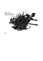
[0042] Фигура 1 показывает вид сбоку модуля пересаживания согласно изобретению. Перемещающий элемент (9) на фигуре 1А имеет фиксированную конфигурацию. Фигура 1В показывает отводной перемещающий элемент, наложенный на модуль пересаживания.[0042] Figure 1 shows a side view of a transplant module according to the invention. The moving element (9) in FIG. 1A has a fixed configuration. Figure 1B shows a retractable transfer member superimposed on a transplant module.
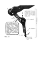
[0043] Фигура 2 показывает части модуля пересаживания согласно одному аспекту изобретения.[0043] Figure 2 shows parts of a transplant module in accordance with one aspect of the invention.
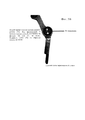
[0044] Фигура 3 показывает поперечное сечение части модуля пересаживания, которая находится в соприкосновении с грунтом, взятое по оси III-III.[0044] Figure 3 shows a cross section of a portion of a transplant module that is in contact with the ground, taken along axis III-III.
[0045] Фигуры 4A и 4B показывают один вариант осуществления режущего средства. На этой фигуре режущее средство (40) прикреплено к круговой детали (41). Лента с растениями (не показано) подается через зазор (43) и карманы с отдельными растениями направляются вперед толкателями перемещающих элементов (см. ниже Фигуру 5). Круговая деталь будет вращаться на 360 градусов вокруг центральной оси, разрезая ленту с растениями между каждым карманом с растением/секцией с проросшим семенем. Режущее средство может иметь такую форму, как показано на фигуре, или любую другую конфигурацию, которая будет разрезать ленту с растениями. Как показано, режущее средство является самоочищающимся ввиду своей ''V-образной'' конфигурации. Фигура 4B такая же, как 4A, за тем исключением, что желтая стрелка указывает направление вращения круговой детали (41), и своей прикрепленное режущее средство (40). Фигура 4C показывает различные края, пригодные для использования в режущем средстве.[0045] Figures 4A and 4B show one embodiment of a cutting means. In this figure, the cutting means (40) is attached to the circular part (41). A ribbon with plants (not shown) is fed through the gap (43) and pockets with individual plants are directed forward by the pushers of the moving elements (see Figure 5 below). The circular part will rotate 360 degrees around the central axis, cutting the ribbon with plants between each pocket with the plant / section with the sprouted seed. The cutting means may have the form shown in the figure, or any other configuration that will cut the tape with the plants. As shown, the cutting means is self-cleaning due to its “V-shaped” configuration. 4B is the same as 4A, except that the yellow arrow indicates the direction of rotation of the circular part (41), and its attached cutting means (40). Figure 4C shows various edges suitable for use in a cutting tool.
[0046] Фигура 5 показывает часть отводного перемещающего элемента. Отводные перемещающие элементы позволяют регулировать размещение саженца, т.е. шаг, при более высокой скорости. Фигура 5А представляет собой рисунок одного варианта осуществления отводного перемещающего элемента. Отводной перемещающий элемент содержит основной рычаг (52) и толкающий рычаг, которые представляют собой единый узел. Толкающий рычаг содержит соединительную секцию (54) и толкатель (55). Синяя стрелка указывает на подшипник, который служит не только для уменьшения трения, но также помогает толкающему рычагу входить в зацепление с каналом в пределах модуля пересаживания, в результате чего отводной рычаг проходит радиально наружу. Это добавление также обеспечивает, чтобы толкатели были правильно выстроены для передвижения карманов с растениями и ленты с растениями по модулю пересаживания. Трактор движется в направлении, указанном стрелкой 1 на фигуре 5A. Фигура 5B представляет собой фотографию второго варианта осуществления отводного перемещающего элемента. Фигура 5C представляет собой фотографию обратной стороны отводного перемещающего элемента. На этом виде ясно показано, что нижний толкающий рычаг является цельным (следует отметить, что он может быть выполнен из множества деталей, но предпочтительно, чтобы он был цельным).[0046] Figure 5 shows a portion of a tap-away moving member. Bypass moving elements allow you to adjust the placement of the seedling, i.e. step at higher speed. Figure 5A is a drawing of one embodiment of a retracting transfer member. The diverting moving element comprises a main lever (52) and a pushing lever, which are a single unit. The pushing lever comprises a connecting section (54) and a pusher (55). The blue arrow indicates the bearing, which not only serves to reduce friction, but also helps the pushing lever to engage with the channel within the transplant module, as a result of which the withdrawal lever extends radially outward. This addition also ensures that the pushers are correctly aligned to move pockets with plants and ribbon with plants modulo transplantation. The tractor moves in the direction indicated by
[0047] Фигура 6 представляет собой фотографию дальнего кончика перемещающего элемента (кончика нижнего толкающего рычага, снятого в направлении соединительного рычага). На переднем плане находится зубец 56. Также виден угол 63, под которым установлена нижняя часть толкателя. Если перемещающий элемент положить на плоскую поверхность, так чтобы зубец 56 находился на обращенной вверх стороне, а обратная сторона (показанная на фигуре 5C) была на плоской поверхности, передний край будет приходить в соприкосновение с плоской поверхностью, а задний край - нет. Также видна рукоять (64) нижнего толкателя.[0047] Figure 6 is a photograph of the distal tip of the moving member (the tip of the lower pushing arm, taken in the direction of the connecting arm). In the foreground there is a
[0048] Фигура 7 представляет собой схематическое изображение вида в поперечном сечении (или с ребра) отводного перемещающего элемента, если смотреть с левого края фигуры 5A. Выступ (57) и подшипник (58) важны для выдерживания правильного положения рычага во время пересадки.[0048] Figure 7 is a schematic cross-sectional view (or from an edge) of a retracting moving member when viewed from the left edge of Figure 5A. The protrusion (57) and the bearing (58) are important to maintain the correct position of the lever during transplantation.
[0049] Фигура 8 представляет собой схематическое изображение толкателя, помогающего поместить карман с растением (секцию с проросшим семенем) в почву. Не показано: пружина и кулачковый упор, действующие на выступ толкателя, отведут толкатель. Сила кулачкового упора прилагается по коричневой стрелке. Пружина оказывает достаточное усилие (т.е. вращающий момент), такое что толкатель удерживается в отведенном положении, если к рычагу не прилагается никакая другая сила. Однако пружины недостаточно, чтобы вернуть толкатель в его отведенное положение, и, когда трактор движется на более высокой скорости, требуется помощь кулачкового упора. Когда толкатель поднимается обратно в отведенное положение кулачковым упором, кончик рычага (где расположен зубец) проходит над растением. Если зубец находится над средней линией (m), то существует тенденция опрокидывать карман с растением, а не помещать растение в вертикальное положение.[0049] Figure 8 is a schematic representation of a pusher helping to place a pocket with a plant (section with a sprouted seed) in the soil. Not shown: the spring and cam stop acting on the protrusion of the pusher will retract the pusher. The force of the cam stop is applied in the brown arrow. The spring exerts sufficient force (i.e., torque) such that the push rod is held in the retracted position if no other force is applied to the lever. However, the spring is not enough to return the pusher to its retracted position, and when the tractor moves at a higher speed, the help of the cam stop is required. When the pusher rises back to the retracted position with the cam stop, the tip of the lever (where the tooth is located) passes over the plant. If the tooth is above the middle line (m), then there is a tendency to tip the pocket with the plant, rather than placing the plant in an upright position.
[0050] Фигура 9 представляет собой крупный план рычага толкателя (со ссылкой на фигуру 5 выше).[0050] Figure 9 is a close-up of the pusher arm (with reference to Figure 5 above).
[0051] Комплект данного патента содержит в себе, по меньшей мере, одно цветное изображение. Копии данного патента или патентной публикации с цветным(-ми) изображением(-ями) будут предоставлены Патентным ведомством по требованию и после уплаты необходимого сбора.[0051] The kit of this patent contains at least one color image. Copies of this patent or patent publication with color (s) image (s) will be provided by the Patent Office upon request and after payment of the necessary fee.
Подробное описаниеDetailed description
[0052] Теперь изобретение будет подробно описано посредством ссылок только с использованием следующих определения и примеров. Все патенты и публикации, в том числе все последовательности, раскрываемые в таких патентах и публикациях, на которые ссылается данная заявка, явным образом включены в данную заявку посредством ссылки.[0052] The invention will now be described in detail by reference only using the following definitions and examples. All patents and publications, including all sequences disclosed in such patents and publications to which this application refers, are expressly incorporated into this application by reference.
[0053] Если не указано обратное, все используемые в данной заявке технические и научные термины имеют то же значение, какое обычно понимается обычным специалистом в области техники, к которой принадлежит данное изобретение. Хотя на практике или при тестировании данного изобретения могут использоваться любые способы и материалы, подобные или эквивалентные тем, что описаны в данной заявке, описываются предпочтительные способы и материалы. Следует понимать, что данное изобретение не ограничивается описанными здесь конкретными технологиями, протоколами и реагентами, поскольку они могут варьироваться.[0053] Unless otherwise indicated, all technical and scientific terms used in this application have the same meaning as commonly understood by one of ordinary skill in the art to which this invention belongs. Although any methods and materials similar or equivalent to those described in this application may be used in practice or in testing this invention, preferred methods and materials are described. It should be understood that the invention is not limited to the specific technologies, protocols, and reagents described herein, as they may vary.
[0054] Числовые диапазоны включают значения, определяющие границы диапазона. Термин ''приблизительно'' в контексте данной заявки означает плюс или минус десть процентов (10%) от значения. Например, ''приблизительно 100'' относится к любому количеству от 90 до 110.[0054] Numerical ranges include values defining the boundaries of the range. The term "approximately" in the context of this application means plus or minus ten percent (10%) of the value. For example, “about 100” refers to any amount from 90 to 110.
[0055] Представленные в данной заявке заголовки не ограничивают различные аспекты или варианты осуществления изобретения, которые можно получить при помощи ссылки на техническое описание в целом. Соответственно, термины, определения которых приводятся непосредственно ниже, полнее определяются ссылкой на техническое описание в целом.[0055] The headings presented in this application do not limit the various aspects or embodiments of the invention that can be obtained by reference to the technical description as a whole. Accordingly, the terms, the definitions of which are given directly below, are more fully determined by reference to the technical description as a whole.
ОпределенияDefinitions
[0056] В контексте данной заявки ''растение'' означает любую часть или стадию развития растения, которая пригодна для высаживания с использованием устройства, описанного в данной заявке. Примеры включают (но не ограничиваются) корневища, семена или саженцы. Предпочтительно растения являются недавно проросшими. В варианте осуществления растение выступает над почвой (или над верхушкой единицы проращивания) меньше чем на 2 дюйма.[0056] In the context of this application, “plant” means any part or stage of development of a plant that is suitable for planting using the device described in this application. Examples include (but are not limited to) rhizomes, seeds, or seedlings. Preferably, the plants are recently germinated. In an embodiment, the plant protrudes less than 2 inches above the soil (or above the top of the germination unit).
[0057] ''Единица проращивания'' представляет собой вставку среды выращивания (например, почвы), содержащую семя (семена) или саженец (саженцы) и носитель (или смесь носителей). В некоторых случаях единица проращивания заключена в поддающийся биологическому разложению материал. Две или больше единицы проращивания, заключенные в поддающийся биологическому разложению материал, могут образовывать ленту с растениями. Дается ссылка на US 7213366, US 7356964 и US 7614181.[0057] A “germination unit” is an insert of a growing medium (eg, soil) containing seed (s) or seedlings (seedlings) and a carrier (or a mixture of carriers). In some cases, the germination unit is enclosed in a biodegradable material. Two or more germination units enclosed in a biodegradable material can form a ribbon with plants. Reference is made to US 7213366, US 7356964 and US 7614181.
[0058] ''Лента с растениями'' представляет собой непрерывную ленту поддающегося биологическому разложению материала, в которую заключены расположенные последовательно единицы проращивания. Лента с растениями может разрезаться на отдельные единицы (также называемые карманами с растениями или единицами проращивания) при использовании с описанным в данной заявке устройством.[0058] A “plant ribbon” is a continuous biodegradable material tape in which germination units are arranged in series. The ribbon with plants can be cut into individual units (also called pockets with plants or germination units) when used with the device described in this application.
[0059] Термин ''носитель'' в контексте данной заявки следует понимать как материал, включающий по меньшей мере одну из субстанций: гранулированный вспученный вермикулит, перлит, цеолит, целлюлозные материалы, такие как древесные волокна и сфагнум, обожженную глину, минеральную вату или подобные субстанции, с которыми возможно получить желаемую степень проводимости воды, свойства ионного обмена и т.д. ''Смесь носителей'' представляет собой по меньшей мере две из приведенных выше субстанций.[0059] The term "carrier" in the context of this application should be understood as a material comprising at least one of the substances: granular expanded vermiculite, perlite, zeolite, cellulosic materials such as wood fibers and sphagnum, calcined clay, mineral wool or similar substances with which it is possible to obtain the desired degree of water conductivity, ion exchange properties, etc. A “carrier mixture” is at least two of the above substances.
[0060] Под термином ''добавка'' в контексте данной заявки следует, главным образом, понимать водопоглощающие материалы, такие как сверхпоглощающие материалы, т.е. с поглощением Н2О, которое достигает буфера влажности, такие как, например, сверхпоглощающие полимеры (SAP).[0060] The term "additive" in the context of this application should mainly mean water-absorbing materials, such as superabsorbent materials, i.e. with absorption of H 2 O, which reaches the moisture buffer, such as, for example, superabsorbent polymers (SAP).
[0061] Выражение ''вспомогательный'' должно пониматься в контексте данной заявки как охватывающее одну или более из субстанций, выбранных из: питательные вещества для растений, защитные вещества для растений, такие как пестициды, в том числе гербициды, инсектициды, особенно системные инсектициды, фунгициды, вирусы, культуры бактерий, культуры грибов, такие как триходерма, грибковые споры, микроинкапсулированные фунгициды, яйца полезных насекомых, таких как хищные нематоды, удобрения, ферменты, средства, отпугивающие животных, гормоны, регуляторы кислотности, активированный уголь, частицы глины, следовые элементы, такие как молибден, деревянные волокна или древесная мука, инфузорная земля, поверхностно-активные вещества или другие субстанции, оказывающие благоприятный эффект на прорастание и рост растений, где некоторые субстанции доступны в микроинкапсулированном виде.[0061] The term "auxiliary" is to be understood in the context of this application as covering one or more of the substances selected from: plant nutrients, plant protective products, such as pesticides, including herbicides, insecticides, especially systemic insecticides fungicides, viruses, bacterial cultures, fungal cultures such as trichoderma, fungal spores, microencapsulated fungicides, eggs of beneficial insects such as carnivorous nematodes, fertilizers, enzymes, animal repellents, hormones, regular Orae acidity, activated carbon, clay particles, trace elements, such as molybdenum, wood fibers or wood flour, diatomaceous earth, surfactants or other substances that have a favorable effect on the germination and plant growth, where several substances are available in microencapsulated form.
[0062] Выражение ''поддающийся биологическому разложению'' материал должно пониматься в контексте данной заявки как материал, постепенно разлагающийся и/или являющийся частью обычной биологической пищевой цепи в пределах обозримого периода, если его оставить в естественном состоянии.[0062] The term “biodegradable” material is to be understood in the context of this application as material that gradually decomposes and / or is part of the normal biological food chain within a visible period, if left in its natural state.
[0063] Фраза ''режущее средство'' относится к любому физическому средству отделения единиц проращивания ленты с растениями. Этот термин не охватывает разбивания или разрывания единиц проращивания. Конкретные варианты осуществления включают ножницы, зазубренные края или ножи. В некоторых вариантах осуществления ножом может быть вогнутый измельчитель, плоский измельчитель, сабельный измельчитель (который иногда называют ''V-измельчитель''), клинообразный измельчитель, с двойным скосом или составной измельчитель или выпуклый измельчитель.[0063] The phrase “cutting agent” refers to any physical means for separating the germination units of a tape with plants. This term does not cover breaking or tearing of germination units. Specific embodiments include scissors, serrated edges, or knives. In some embodiments, the knife may be a concave chopper, a flat chopper, a reciprocating chopper (sometimes called a `` V-chopper ''), a wedge-shaped chopper, with a double bevel, or a compound chopper or convex chopper.
[0064] Фиг. 1 показывает вид сбоку модуля 1 пересаживания для пересаживания множества растений 2. Модуль 1 содержит пластину 3 скольжения, конфигурация которой приспособлена для соприкосновения с поверхностью грунта во время пересадки. Пластина 3 скольжения обладает функцией уплотнения отведенного под посадку грунта, поскольку пластина скольжения несет вес части модуля 1 во время пересадки, и поэтому оказывает давление на грунт или почву. Пластина 3 скольжения также обладает функцией недопущения, чтобы модуль проваливался в грунт, так чтобы части модуля 1 пересаживания, которые расположены под пластиной скольжения, проникали в грунт/почву на заданное расстояние.[0064] FIG. 1 shows a side view of a
[0065] Модуль 1 дополнительно содержит киль 4, который приспособлен проникать в грунт и создавать борозду в грунте, как показано на фиг. 3. Киль содержит верхний край 5 и нижний край 6, где нижний край киля определяет глубину борозды, которую должен создать модуль. Киль 4 может также служить средством переноса для подлежащего пересаживанию растения 2, где растение 2 может скользить по верхнему краю 5 киля в направлении дальнего конца 7 модуля, так чтобы растение 2 входило в борозду в той же плоскости, что и плоскость киля 4. В отдалении от киля модуль 1 может обеспечиваться средствами 8 уплотнения, которые устроены так, чтобы приходить в соприкосновение с почвой по бокам борозды, и могут быть приспособлены уплотнять стороны борозды, тем самым закрывая борозду после введения растения 2 в борозду. Средства 8 уплотнения могут быть устроены так, чтобы обеспечивать давление на почву по бокам борозды, вызывая осыпание боковых стенок борозды, так чтобы боковые стенки борозды охватывали боковые стенки растения 2.[0065]
[0066] Растение может перемещаться из устройства вниз в направлении верхнего края 5 киля, где движению перемещения может способствовать перемещающий элемент 9, который соединяется с растением и проталкивает растение по средству переноса и вдоль верхнего края 5 киля 4, пока растение не пройдет дальний конец 10 киля. Перемещающий элемент 9 может обеспечиваться в виде вращающегося перемещающего элемента, который приспособлен вращаться внутри модуля на вращающемся приводе 11, который приводит в действие перемещающий элемент 9. Средство перемещения может обеспечиваться в виде множества перемещающих элементов, которые расположены последовательно вдоль вращающегося привода 11, где каждый перемещающий элемент может быть приспособлен перемещать одно растение, а следующий перемещающий элемент 9 может перемещать следующее растение из устройства в борозду.[0066] The plant can move downward from the device toward the top edge of the
[0067] Модуль 1 может крепиться к транспортному средству при помощи средства 12 сцепления, которое может быть приспособлено прикрепляться к задней части транспортного средства и позволять модулю подниматься и/или опускаться и позволять транспортному средству тянуть модуль 1 по почве во время операции пересаживания, обеспечивая движение в направлении пересаживания.[0067] The
[0068] Фиг. 2 показывает вид сбоку частей модуля 1 пересаживания, где некоторые части модуля удалены, чтобы показать механизм пересаживания согласно изобретению. Приводной механизм 11 может приводить в действие цепь 17, которая расположена вокруг первого зубчатого колеса 18 и второго зубчатого колеса 19, где движущая сила передается на цепь при помощи первого 18 или второго зубчатого колеса 19 и приводит цепь в движение в направлении D по кольцу. Зубчатые колеса 18, 19 разделены расстоянием, так чтобы цепь 17 содержала две продольные стороны, где цепь в целом прямая, и две зоны, где цепь поворачивает на 180 градусов по зубчатому колесу от одной продольной стороны к другой. Цепь может обеспечиваться множеством перемещающих элементов 9, которые содержат ближний конец 15, который прикреплен к цепи 17, и дальний конец, который приспособлен соединяться с растением 2.[0068] FIG. 2 shows a side view of the parts of the
[0069] Когда модуль 1 применяется для операции пересаживания, перемещающие элементы вращаются в направлении D, где перемещающие элементы 9А устроены так, чтобы соединяться с растением 2, когда растение находится на средстве 13 переноса внутри устройства. Продолжающееся вращение приводит к тому, что растение 2 проталкивается в целом прямо в направлении нижнего конца модуля в направлении грунта 14. Когда растение 2B достигает ближнего конца киля 4, средство перемещения 9B начинает вращаться вместе с цепью вдоль зубчатого колеса 18, заставляя дальний конец 16 средства перемещения двигаться с большей скоростью, чем ближний конец 15, поскольку дальний конец будет проходить большее расстояние E за то же время, за которое вращение происходит рядом с зубчатым колесом. Во время этого увеличения скорости растение 2A вводится под пластину 3 скольжения из положения над грунтом, показанного стрелкой B, в положение под грунтом, показанное стрелкой C. Растение может скользить по верхнему краю 5 киля 4 в направлении дальнего конца 10 киля 4, где изгиб дальнего конца перемещающего элемента 9C в целом такой же, как изгиб средства переноса под грунтом, т.е. верхнего края 5 киля. Изгиб дальнего конца 16 перемещающего элемента 9 может быть в целом таким же, как изгиб средства 13 переноса внутри устройства и средства переноса под грунтом, так чтобы растение можно было безопасно передвигать перемещающим элементом по средству 13, 5 переноса.[0069] When the
[0070] После завершения проталкивания растения в направлении дальнего конца 10 киля 4, боковые стенки борозды приходят в соприкосновение с боковыми стенками растения 2B, и трение между боковой стенкой борозды и растения приводит к тому, что растение движется в направлении, противоположном направлению А хода, и перемещающий элемент может высвобождать растение. После того, как перемещающий элемент 9C высвобождает растение, перемещающий элемент будет поворачиваться вместе с цепью в положение перемещающего элемента 9D, поднимая дальний конец перемещающего элемента из борозды и от грунта 14.[0070] After the pushing of the plant towards the
[0071] После того как перемещающий элемент 9C высвобождает растение 2, следующий перемещающий элемент продолжит непрерывную операцию высаживания, проталкивая следующее растение таким же образом, как предыдущее растение, и высаживая следующее растение в борозду, создаваемую килем 4.[0071] After the moving element 9C releases the
[0072] Растения 2, которые имеются в средстве переноса, можно постоянно пополнять во время операции, обеспечивая, чтобы имелось достаточно растений, чтобы непрерывно пересаживать растения непрерывным образом в ряд. Пополнение средства 13 переноса может выполняться различными путями и может рассматриваться как часть навыков специалиста в области техники, на основе данного описания.[0072] The
[0073] Фиг. 3 представляет собой чертеж в поперечном сечении, взятом по оси III-III на фиг. 2, где этот чертеж показывает работу модуля во время пересадки и взаимодействие с грунтом 20, видимое в направлении хода A, показанном на фиг. 2. Пластина 3 скольжения примыкает к поверхности 14 грунта 20, обеспечивая, чтобы модуль не проваливался в грунт под поверхностью контакта с почвой пластины 3 скольжения. Пластина 3 скольжения может иметь вид лыжи, имеющей ближний конец 21, который отклоняется от поверхности 14 почвы. Пластина скольжения может быть выполнена из двух слоев, нижнего слоя 22, который предназначен для износа и является сменным, и верхнего слоя 23, который защищен сменным нижним слоем 22. Когда нижний слой 22 изнашивается, его можно снимать с верхнего слоя 23 и заменять новым нижним слоем 22, обеспечивая, чтобы снашивались только части пластины 3 скольжения, тогда как остальные части могли использоваться повторно. Пластина 3 скольжения может обеспечиваться сквозной канавкой 23, создающей проход от верхней зоны пластины скольжения к нижней зоне пластины 3 скольжения и тем самым создающей проход в направлении грунта 20.[0073] FIG. 3 is a cross-sectional drawing taken along axis III-III of FIG. 2, where this drawing shows the operation of the module during transplantation and the interaction with the
[0074] Во время операции пересаживания киль 4 проникает в грунт 20, создавая борозду 24 в грунте 20, где глубина борозды определяется нижним краем 6 киля 4, который создает дно 30 борозды. Ширина борозды 24 контролируется боковыми стенками 26, 27 киля 4, так чтобы борозда обеспечивалась соответствующими боковыми стенками 28, 29.[0074] During the transplant operation, the
[0075] Верхний край 5 киля 4 может использоваться, чтобы переносить растение 2 в борозду, тем самым отделяя растение 2 от дна 30 борозды. Высота киля 4 определяет расстояние, на которое дно 30 борозды отделено от растения 2, где это расстояние можно контролировать, выбирая размер киля в зависимости от того, какой тип растения вводится в борозду 24.[0075] The
[0076] Верхний край киля поддерживает растение снизу и обеспечивает, чтобы растение не падало в борозду перед выгрузкой. Модуль может дополнительно обеспечиваться опорным элементом 31, который содержит край 32, приспособленный поддерживать растение сверху, не допуская движения растения 2 в вертикальном направлении вверх во время пересадки, обеспечивая, чтобы растение не выскакивало из борозды во время пересадки. Модуль 1 может дополнительно обеспечиваться опорным элементом 33 первой стороны и опорным элементом 34 второй стороны, которые обеспечивают, чтобы растение не двигалось в поперечном (боковом) направлении во время пересадки, и удерживают растение на верхнем краю 5 киля 4. Опорный элемент 34 может применяться только к частям длины киля 4, где боковая поддержка растения с этой стороны может быть необходимой только в то время, когда растение входит в борозду 24.[0076] The upper edge of the keel supports the plant from below and ensures that the plant does not fall into the furrow before unloading. The module may be further provided with a
[0077] Средства 5, 31, 32, 33, 34 переноса внутри грунта могут обеспечиваться отверстием 35, позволяющим боковым стенкам 28, 29 борозды приходить в соприкосновение с растением, когда его перемещают в направлении, противоположном направлению хода, позволяя импульсу грунта помогать перемещению по средству переноса и снижать давление, оказываемое на перемещающий элемент 9 растением во время пересадки. Более того, отверстие может помогать удерживать поперечное положение растения на верхнем краю 5 киля, пока не закончится выгрузка, поскольку боковые стенки борозды давят на растение. Таким образом, возможно ограничивать длину боковых опорных элементов в дальнем направлении модуля, где боковая стенка может, например, перенимать на себя боковую поддержку растения 2, когда растение достигает определенной точки на верхнем краю 5 киля 4.[0077] The transfer means 5, 31, 32, 33, 34 inside the soil can be provided with an opening 35, allowing the
[0078] Благодаря тому, что боковой стенке обеспечивается возможность приходить в соприкосновение с растением, растение 2 приобретает скорость, которая равняется грунту, а это означает, что, когда растение выгружается, боковые стенки не причиняют удара или внезапного приложения силы к растению, где такой удар мог бы повредить растению во время операции пересаживания или нарушить положение растения после выгрузки.[0078] Due to the fact that the side wall is able to come into contact with the plant,
[0079] Глубина киля 4 и нижнего периферийного края 6 киля может регулироваться согласно желаемой глубине борозды для конкретного растения, так чтобы расстояние, которое киль проходит под грунтом, можно было менять. Таким же образом расстояние между верхним краем 5 киля 4 и опорным элементом 34 и элементом 31 можно регулировать согласно высоте растения, обеспечивая, чтобы контур поперечного сечения средства переноса соответствовал контуру поперечного сечения растения.[0079] The depth of the
[0080] Более того, при использовании ленты с растениями для высадки растений может устанавливаться режущее средство, например ножницы или нож, для разрезания ленты с растениями на небольшие отрезки или единицы ленты, где каждый отрезок ленты включает одно или более растение. Получаемую в результате процедуру отделения очень легко осуществлять, когда желательно разделить ленту с растениями на единицы проращивания.[0080] Moreover, when using a tape with plants for planting plants, cutting means, such as scissors or a knife, can be installed to cut the tape with the plants into small pieces or tape units, where each piece of tape includes one or more plants. The resulting separation procedure is very easy to carry out when it is desirable to divide the ribbon with plants into germination units.
[0081] Фигура 4A показывает один вариант осуществления режущего средства. В частности, изображен самоочищающийся нож, который содержит сабельный измельчитель. Режущее средство будет сбрасывать любую приставшую грязь или мусор с лопасти, когда будет разрезать ленту с растениями. Другими словами, ткань ленты с растениями вытирает грязь, поддерживая количество грязи, слякоти и/или мусора на лопасти на минимальном уровне.[0081] Figure 4A shows one embodiment of a cutting means. In particular, a self-cleaning knife is shown that contains a reciprocating chopper. The cutting tool will dump any adhering dirt or debris from the blade when it cuts the tape with the plants. In other words, the cloth tape wipes the dirt off the plants, keeping the amount of dirt, slush and / or debris on the blades to a minimum.
[0082] Режущее средство прикреплено к круговому средству, которое вращается, как показано на фигуре 4B желтой стрелкой. Вращение происходит вокруг центральной оси, перпендикулярной лицевой поверхности круговой детали. Альтернатива заключается в том, чтобы режущее средство могло чередовать движения вперед и назад, а не поворачиваться на все 360 градусов. Однако эта альтернатива может привести к тому, что режущее средство будет бить по толкателям.[0082] The cutting means is attached to the circular means, which rotates, as shown in figure 4B with a yellow arrow. The rotation occurs around a central axis perpendicular to the face of the circular part. An alternative is for the cutting tool to alternate back and forth, rather than turning 360 degrees. However, this alternative may cause the cutting tool to hit the pushers.
[0083] Фигура 5A-C изображает часть отводного перемещающего элемента с сомкнутыми толкателями перемещающего элемента.[0083] Figure 5A-C depicts a portion of a retractable moving member with closed pushers of the moving member.
[0084] Отводные толкатели средства перемещения позволяют оставлять меньше места между растениями и быстрее производить операцию пересадки. Отводные толкатели начинают отводиться, когда средство перемещения в целом перпендикулярно поверхности почвы.[0084] The follower pushers of the moving means allow less space between the plants and a faster transplant operation. Bypass pushers begin to retract when the means of movement is generally perpendicular to the surface of the soil.
[0085] Благодаря воздействию пружины и кулачкового упора на выступ толкателя толкатель отводится. Сила кулачкового упора прилагается по коричневой стрелке. Пружина оказывает достаточное усилие (т.е. вращающий момент), такое, что толкатель удерживается в отведенном положении, если к рычагу не прилагается никакая другая сила. Однако пружины недостаточно, чтобы вернуть толкатель в его отведенное положение, и требуется помощь кулачкового упора. Когда толкатель поднимается обратно в отведенное положение кулачковым упором, кончик рычага (где расположен зубец) проходит над растением.[0085] Due to the action of the spring and cam stop on the protrusion of the pusher, the pusher is retracted. The force of the cam stop is applied in the brown arrow. The spring exerts sufficient force (i.e., torque) such that the plunger is held in the retracted position if no other force is applied to the lever. However, the spring is not enough to return the pusher to its retracted position, and the help of the cam stop is required. When the pusher rises back to the retracted position with the cam stop, the tip of the lever (where the tooth is located) passes over the plant.
[0086] Если зубец находится над средней линией (m), то существует тенденция опрокидывать карман с растением, а не помещать растение в вертикальное положение.[0086] If the prong is above the midline (m), then there is a tendency to tip the pocket with the plant, rather than placing the plant in an upright position.
[0087] Различные культуры требуют различных расстояний между растениями при пересадке. Таким образом, желательно иметь возможность повышать/понижать плотность высаживания культуры при высаживании разных культур. Например, при выращивании спаржевой капусты между растениями, как правило, оставляют 3 дюйма, тогда как при выращивании цветной капусты между растениями оставляют 18-24 дюймов. При выращивании латука между растениями, как правило, оставляют 6-12 дюймов. Чтобы учесть эти различия, используется коробка передач.[0087] Different crops require different distances between plants when transplanted. Thus, it is desirable to be able to increase / decrease the density of planting crops when planting different crops. For example, when growing asparagus cabbage between plants, usually leave 3 inches, while when growing cauliflower between plants leave 18-24 inches. When growing lettuce between plants, as a rule, leave 6-12 inches. To account for these differences, a gearbox is used.
[0088] Понятно, что описанные в данной заявке примеры и варианты осуществления приводятся только для иллюстративных целей и что в их свете специалистами в области техники будут предлагаться различные модификации или изменения, которые должны быть включены в предмет и содержание данной заявки и в объем прилагаемой формулы изобретения. Все приводимые здесь публикации, патенты и патентные заявки полностью включаются в данную заявку посредством ссылки для всех целей.[0088] It is understood that the examples and embodiments described in this application are for illustrative purposes only and that various modifications or changes will be proposed by those skilled in the art that should be included in the subject and contents of this application and in the scope of the attached claims inventions. All publications, patents, and patent applications cited herein are hereby incorporated by reference in their entirety for all purposes.
Список источниковList of sources
Патентная литератураPatent Literature
[1] US 7421960 - Machine For Bedding Out Seed or Plant Tapes.[1] US 7421960 - Machine For Bedding Out Seed or Plant Tapes.
[2] US 7213366 - Mixture of a carrier and additives for use in germinating units containing seeds or similar growth-suited parts of a plants as well as a method of producing the mixture.[2] US 7213366 - Mixture of a carrier and additives for use in germinating units containing seeds or similar growth-suited parts of a plants as well as a method of producing the mixture.
[3] US 7356964 - Seed tape including successively arranged germinating units as well as a method of germinating the seed tape.[3] US 7356964 - Seed tape including successively arranged germinating units as well as a method of germinating the seed tape.
[4] US 7614181 - Seed tape including successively arranged germinating units.[4] US 7614181 - Seed tape including successively arranged germinating units.
Claims (22)
Applications Claiming Priority (4)
| Application Number | Priority Date | Filing Date | Title |
|---|---|---|---|
| DKPA201370660 | 2013-11-08 | ||
| DKPA201370660 | 2013-11-08 | ||
| US201462021042P | 2014-07-04 | 2014-07-04 | |
| US62/021,042 | 2014-07-04 |
Publications (2)
| Publication Number | Publication Date |
|---|---|
| RU2014143801A RU2014143801A (en) | 2016-05-20 |
| RU2630904C2 true RU2630904C2 (en) | 2017-09-14 |
Family
ID=52594865
Family Applications (1)
| Application Number | Title | Priority Date | Filing Date |
|---|---|---|---|
| RU2014143801A RU2630904C2 (en) | 2013-11-08 | 2014-10-30 | Device for transplanting plants |
Country Status (17)
| Country | Link |
|---|---|
| US (1) | US9763382B2 (en) |
| EP (1) | EP2870847B1 (en) |
| JP (1) | JP6208112B2 (en) |
| CN (1) | CN104663084B (en) |
| AR (1) | AR098322A1 (en) |
| AU (1) | AU2014250663C1 (en) |
| BR (1) | BR102014027918B1 (en) |
| CA (1) | CA2869484C (en) |
| DK (1) | DK2870847T3 (en) |
| ES (1) | ES2641204T3 (en) |
| HK (1) | HK1210912A1 (en) |
| IL (1) | IL235538B (en) |
| IN (1) | IN2014DE03170A (en) |
| MX (1) | MX358186B (en) |
| PL (1) | PL2870847T3 (en) |
| PT (1) | PT2870847T (en) |
| RU (1) | RU2630904C2 (en) |
Families Citing this family (10)
| Publication number | Priority date | Publication date | Assignee | Title |
|---|---|---|---|---|
| CN108370683B (en) * | 2018-02-07 | 2019-11-05 | 泰兴市东城水处理工程有限公司 | Forest excavates soil-discharging device with automatic tree well |
| WO2020227681A1 (en) | 2019-05-09 | 2020-11-12 | 80 Acres Urban Agriculture Inc. | Method and apparatus for high-density indoor farming |
| AU2020274162B2 (en) | 2019-05-13 | 2023-11-30 | 80 Acres Urban Agriculture, Inc. | System and method for controlling indoor farms remotely and user interface for same |
| CN110506472B (en) * | 2019-08-28 | 2022-02-22 | 山西工程技术学院 | Automatic seedling separating transplanter |
| CN110972646B (en) * | 2019-12-03 | 2023-12-05 | 农业农村部南京农业机械化研究所 | Pneumatic ordered seedling throwing machine suitable for degradable seedling tray and seedling throwing method |
| CN110771325B (en) * | 2019-12-10 | 2020-12-18 | 厦门安鑫鹭建设工程有限公司 | Gardens nursery stock is transplanted and is used solid native mechanism fast |
| US11521382B2 (en) | 2020-02-09 | 2022-12-06 | Stout Industrial Technology, Inc. | Machine vision plant tracking system for precision agriculture |
| EP4099811A1 (en) | 2020-02-09 | 2022-12-14 | Stout Industrial Technology, Inc. | Modular smart implement for precision agriculture |
| US11864486B2 (en) * | 2020-09-23 | 2024-01-09 | Square Rooted, Llc | Automated planter apparatus |
| CN114158317A (en) * | 2021-12-28 | 2022-03-11 | 陈倩倩 | Sweet potato planting device and sweet potato planting method |
Citations (5)
| Publication number | Priority date | Publication date | Assignee | Title |
|---|---|---|---|---|
| US4106415A (en) * | 1976-04-30 | 1978-08-15 | Lannen Tehtaat Oy | Plant-setting machine |
| EP0137399A2 (en) * | 1983-09-26 | 1985-04-17 | Lännen Tehtaat Oy | Method and equipment for planting of band ball plants |
| SU1553027A1 (en) * | 1987-01-28 | 1990-03-30 | А.Н.Раскар ка | Mounted mechanized planter |
| RU18220U1 (en) * | 2000-11-13 | 2001-06-10 | Открытое акционерное общество "Уральский научно-исследовательский технологический институт" | Seedling machine |
| WO2004107843A2 (en) * | 2003-06-04 | 2004-12-16 | Cellfor Inc. | Device for assisting transplanting of seedlings, machine incorporating the device, and method using the device |
Family Cites Families (21)
| Publication number | Priority date | Publication date | Assignee | Title |
|---|---|---|---|---|
| US2145771A (en) * | 1937-04-28 | 1939-01-31 | Allen Pfost | Transplanter |
| US2475078A (en) * | 1945-08-07 | 1949-07-05 | Willie K Cherry | Transplanter drill set |
| DE849197C (en) * | 1948-10-02 | 1952-09-11 | Beche & Grohs Ges Mit Beschrae | Planting machine for planting out vegetable plants grown in soil or the like. |
| FR1085381A (en) | 1953-03-07 | 1955-02-02 | Wheel for planting machine for cabbages, beets, potatoes, etc. | |
| US2831442A (en) | 1954-09-29 | 1958-04-22 | Montguire David Murray | Transplanter machine |
| GB886146A (en) | 1959-09-02 | 1962-01-03 | Paul Gerhard Stock | Improvements in and relating to planting machines |
| FR77956E (en) | 1960-02-22 | 1962-05-18 | Further training at the planter distributor | |
| DE2309879C2 (en) * | 1973-02-28 | 1974-11-28 | Heinrich Weiste & Co Gmbh, 4770 Soest | Transplanter |
| JPS57163401A (en) * | 1981-04-01 | 1982-10-07 | Iseki Agricult Mach | Planting apparatus of vegetable seedling |
| DK171407B1 (en) | 1984-11-12 | 1996-10-21 | Bentle Products Ag | Collapsible or foldable plant strip with longitudinal strips arranged one after the other containing bushes containing plants or growth-suitable plant parts and method for producing the same |
| US4644880A (en) * | 1985-02-22 | 1987-02-24 | Growers Transplanting, Inc. | Method and apparatus for transplanting corps |
| DK168725B1 (en) * | 1985-09-24 | 1994-05-30 | Bentle Products Ag | Method and apparatus for planting ribbons with plants |
| BE1004625A3 (en) * | 1990-11-23 | 1992-12-22 | Perdu Geert | Agricultural machine for MECHANICAL PLANTING IN ADVANCE PRESS POTS SEEDED CROPS. |
| JP2876397B2 (en) | 1996-03-01 | 1999-03-31 | 本田技研工業株式会社 | Seedling raising sheet, method for producing seedling raising sheet, method for raising seedling, cultivation method and transplanter |
| DK173999B1 (en) | 1998-06-29 | 2002-04-02 | Bentle Products Ag | Mixture of a carrier and additives for use in germinating elements containing seeds or similar growth-suitable plant parts and process for preparing the mixture |
| SI1549125T1 (en) | 2002-09-25 | 2012-01-31 | Bentle Products Ag | A seed tape including successively arranged germinating units as well as a method of germinating said tape |
| DK176248B1 (en) | 2003-07-04 | 2007-04-23 | Bentle Products Ag | Seed band consisting of successively arranged germinating elements |
| DK200301535A (en) | 2003-10-20 | 2005-04-21 | Bentle Products Ag | Seed or seedling planting machine |
| AU2007100035B9 (en) | 2006-01-17 | 2013-10-31 | Transplant Systems Pty Limited | Transplanting apparatus |
| CN202151051U (en) * | 2011-07-05 | 2012-02-29 | 胡国永 | 2ZT-2 type beet transplanter |
| CN203120439U (en) * | 2013-01-17 | 2013-08-14 | 山东临沂烟草有限公司 | Tobacco seedling under-film transplanting machine |
-
2014
- 2014-10-16 AU AU2014250663A patent/AU2014250663C1/en active Active
- 2014-10-30 RU RU2014143801A patent/RU2630904C2/en active
- 2014-11-03 IN IN3170DE2014 patent/IN2014DE03170A/en unknown
- 2014-11-04 CA CA2869484A patent/CA2869484C/en active Active
- 2014-11-05 JP JP2014225086A patent/JP6208112B2/en active Active
- 2014-11-06 IL IL235538A patent/IL235538B/en active IP Right Grant
- 2014-11-06 AR ARP140104169A patent/AR098322A1/en active IP Right Grant
- 2014-11-06 MX MX2014013512A patent/MX358186B/en active IP Right Grant
- 2014-11-07 BR BR102014027918-0A patent/BR102014027918B1/en active IP Right Grant
- 2014-11-07 PL PL14192374T patent/PL2870847T3/en unknown
- 2014-11-07 DK DK14192374.8T patent/DK2870847T3/en active
- 2014-11-07 PT PT141923748T patent/PT2870847T/en unknown
- 2014-11-07 EP EP14192374.8A patent/EP2870847B1/en active Active
- 2014-11-07 ES ES14192374.8T patent/ES2641204T3/en active Active
- 2014-11-07 US US14/536,541 patent/US9763382B2/en active Active
- 2014-11-10 CN CN201410642989.6A patent/CN104663084B/en not_active Expired - Fee Related
-
2015
- 2015-11-27 HK HK15111734.1A patent/HK1210912A1/en unknown
Patent Citations (5)
| Publication number | Priority date | Publication date | Assignee | Title |
|---|---|---|---|---|
| US4106415A (en) * | 1976-04-30 | 1978-08-15 | Lannen Tehtaat Oy | Plant-setting machine |
| EP0137399A2 (en) * | 1983-09-26 | 1985-04-17 | Lännen Tehtaat Oy | Method and equipment for planting of band ball plants |
| SU1553027A1 (en) * | 1987-01-28 | 1990-03-30 | А.Н.Раскар ка | Mounted mechanized planter |
| RU18220U1 (en) * | 2000-11-13 | 2001-06-10 | Открытое акционерное общество "Уральский научно-исследовательский технологический институт" | Seedling machine |
| WO2004107843A2 (en) * | 2003-06-04 | 2004-12-16 | Cellfor Inc. | Device for assisting transplanting of seedlings, machine incorporating the device, and method using the device |
Also Published As
| Publication number | Publication date |
|---|---|
| AU2014250663A1 (en) | 2015-05-28 |
| HK1210912A1 (en) | 2016-05-13 |
| MX358186B (en) | 2018-08-07 |
| PT2870847T (en) | 2017-09-28 |
| EP2870847B1 (en) | 2017-06-21 |
| MX2014013512A (en) | 2016-04-26 |
| IN2014DE03170A (en) | 2015-07-10 |
| CA2869484C (en) | 2018-06-12 |
| IL235538A0 (en) | 2015-02-26 |
| DK2870847T3 (en) | 2017-10-02 |
| AU2014250663C1 (en) | 2017-10-19 |
| BR102014027918B1 (en) | 2020-08-18 |
| JP2015092883A (en) | 2015-05-18 |
| PL2870847T3 (en) | 2018-01-31 |
| CN104663084A (en) | 2015-06-03 |
| IL235538B (en) | 2018-10-31 |
| EP2870847A1 (en) | 2015-05-13 |
| RU2014143801A (en) | 2016-05-20 |
| ES2641204T3 (en) | 2017-11-08 |
| JP6208112B2 (en) | 2017-10-04 |
| AU2014250663B2 (en) | 2017-06-01 |
| US9763382B2 (en) | 2017-09-19 |
| US20150150188A1 (en) | 2015-06-04 |
| CA2869484A1 (en) | 2015-05-08 |
| AR098322A1 (en) | 2016-05-26 |
| CN104663084B (en) | 2019-02-12 |
| BR102014027918A2 (en) | 2015-09-08 |
Similar Documents
| Publication | Publication Date | Title |
|---|---|---|
| RU2630904C2 (en) | Device for transplanting plants | |
| EP3547816B1 (en) | Apparatus for planting tree seedlings | |
| Kumar et al. | Development of a walk-behind type hand tractor powered vegetable transplanter for paper pot seedlings | |
| CN104823804B (en) | Method for Chinese pine seedling cultivation and afforestation in dry and stony sunny slope | |
| AU2007100035A4 (en) | Transplanting apparatus | |
| Kumawat et al. | Design and development of a tractor drawn automatic onion transplanter | |
| CN115226509A (en) | Tea seedling cuttage method | |
| CN102119598A (en) | Paddy seedling raising/seedling pulling machine | |
| CN201938056U (en) | Rice seedling raising and pulling machine | |
| JP7226231B2 (en) | Raising seedling soil | |
| CN217986125U (en) | Agricultural planting seedling raising plate | |
| CN213880947U (en) | Multifunctional harvesting system combined with meshes | |
| JP2002125454A (en) | Method for planting seedling of rush (juncus effusus), and method for cultivating seedling of rush | |
| JP6720782B2 (en) | How to create mixed seedlings | |
| JP2002095313A (en) | Seedling transplanter | |
| BRMU8901454U2 (en) | multifunctional stem crop planting equipment | |
| JP2002291347A (en) | Method for raising rush seedling and method for cultivating rush | |
| Hauser | An automatic grass transplanting machine | |
| JP2009082043A (en) | Raising seedling method | |
| JP2009082043A5 (en) | ||
| JPH08252007A (en) | Seedling transplantation apparatus | |
| JPH11332384A (en) | Raising and transplatation of seedling | |
| JP2678353C (en) |