RU2607752C9 - Winding device - Google Patents
Winding device Download PDFInfo
- Publication number
- RU2607752C9 RU2607752C9 RU2015101513A RU2015101513A RU2607752C9 RU 2607752 C9 RU2607752 C9 RU 2607752C9 RU 2015101513 A RU2015101513 A RU 2015101513A RU 2015101513 A RU2015101513 A RU 2015101513A RU 2607752 C9 RU2607752 C9 RU 2607752C9
- Authority
- RU
- Russia
- Prior art keywords
- base plate
- segments
- shaft
- supported
- segment
- Prior art date
Links
Images


Classifications
-
- B—PERFORMING OPERATIONS; TRANSPORTING
- B29—WORKING OF PLASTICS; WORKING OF SUBSTANCES IN A PLASTIC STATE IN GENERAL
- B29D—PRODUCING PARTICULAR ARTICLES FROM PLASTICS OR FROM SUBSTANCES IN A PLASTIC STATE
- B29D30/00—Producing pneumatic or solid tyres or parts thereof
- B29D30/06—Pneumatic tyres or parts thereof (e.g. produced by casting, moulding, compression moulding, injection moulding, centrifugal casting)
- B29D30/48—Bead-rings or bead-cores; Treatment thereof prior to building the tyre
- B29D30/50—Covering, e.g. by winding, the separate bead-rings or bead-cores with textile material, e.g. with flipper strips
-
- B—PERFORMING OPERATIONS; TRANSPORTING
- B21—MECHANICAL METAL-WORKING WITHOUT ESSENTIALLY REMOVING MATERIAL; PUNCHING METAL
- B21F—WORKING OR PROCESSING OF METAL WIRE
- B21F37/00—Manufacture of rings from wire
-
- B—PERFORMING OPERATIONS; TRANSPORTING
- B29—WORKING OF PLASTICS; WORKING OF SUBSTANCES IN A PLASTIC STATE IN GENERAL
- B29D—PRODUCING PARTICULAR ARTICLES FROM PLASTICS OR FROM SUBSTANCES IN A PLASTIC STATE
- B29D30/00—Producing pneumatic or solid tyres or parts thereof
- B29D30/06—Pneumatic tyres or parts thereof (e.g. produced by casting, moulding, compression moulding, injection moulding, centrifugal casting)
- B29D30/48—Bead-rings or bead-cores; Treatment thereof prior to building the tyre
- B29D2030/487—Forming devices for manufacturing the beads
Abstract
Description
ОБЛАСТЬ ТЕХНИКИ, К КОТОРОЙ ОТНОСИТСЯ ИЗОБРЕТЕНИЕTECHNICAL FIELD TO WHICH INVENTION RELATES.
Настоящее изобретение относится к намоточному устройству для образования бортового кольца посредством наматывания проволоки на внешнюю окружность вращательного корпуса.The present invention relates to a winding device for forming a bead ring by winding a wire onto the outer circumference of a rotary body.
ПРЕДШЕСТВУЮЩИЙ УРОВЕНЬ ТЕХНИКИPRIOR ART
Одно такое намоточное устройство имеет канавку для наматывания проволоки на внешнюю окружность дискообразного вращательного корпуса. Вращательный корпус вращается в одном направлении для наматывания проволоки накладывающимся друг на друга образом в направлении наслоения в состоянии, выровненном в направлении ряда в канавке, таким образом, образуя бортовое кольцо.One such winding device has a groove for winding a wire on the outer circumference of the disc-shaped rotary body. The rotary body rotates in the same direction to wind the wire in an overlapping manner in the direction of layering in a state that is aligned in the direction of the row in the groove, thus forming a bead ring.
ДОКУМЕНТЫ ПРЕДШЕСТВУЮЩЕГО УРОВНЯ ТЕХНИКИDOCUMENTS OF THE PRIOR ART
Патентные документыPatent documents
Патентный документ 1: открытая японская патентная публикация No. 2000-334858Patent Document 1: Japanese Open Patent Publication No. 2000-334858
КРАТКОЕ ИЗЛОЖЕНИЕ СУЩНОСТИ ИЗОБРЕТЕНИЯSUMMARY OF THE INVENTION
Проблемы, которые подлежат решению посредством изобретенияProblems to be solved by the invention
В зависимости от намеченного использования, может требоваться, чтобы бортовые кольца имели разные диаметры наматывания. Однако, если бортовое кольцо образовано, используя намоточное устройство, описанное в патентном документе 1, является трудным изменить диаметр наматывания бортового кольца не только на значительную величину, но также на незначительную величину. Таким образом, вышеупомянутое требование трудно удовлетворить.Depending on the intended use, it may be required that the bead rings have different winding diameters. However, if the bead ring is formed using the winding device described in Patent Document 1, it is difficult to change the coil diameter of the bead ring not only by a significant amount, but also by a small amount. Thus, the above requirement is difficult to satisfy.
Настоящее изобретение фокусируется на этой проблеме традиционной технологии. Соответственно, целью изобретения является обеспечение намоточного устройства, способного легко изменять диаметр наматывания бортового кольца. Намоточное устройство обеспечивает легкое изменение диаметра наматывания бортового кольца, независимо от того, изменяется ли он на небольшую величину или большую величину.The present invention focuses on this problem of traditional technology. Accordingly, it is an object of the invention to provide a winding device capable of easily changing the diameter of the winding of the bead ring. The winding device provides an easy change in the diameter of the winding of the side ring, regardless of whether it changes by a small amount or a large amount.
Средства для решения проблемRemedies
Для достижения вышеприведенной цели и в соответствии с одним аспектом настоящего изобретения, обеспечено намоточное устройство, которое включает в себя базовую плиту, которая вращается посредством вращательного вала, множество сегментов, размещенных в кольцевой зоне, соответствующей внешней окружности базовой плиты, вал манипулирования, который вращается посредством рукоятки, и механизм преобразования. Каждый из сегментов имеет форму, соответствующую одной из форм, полученных посредством разделения кольцевой зоны на множество секций вдоль окружности базовой плиты. Каждый из сегментов поддерживается базовой плитой, каждый подвижным образом в радиальном направлении базовой плиты. Вал манипулирования вращается посредством рукоятки. Когда базовая плита вращается, проволока наматывается на внешнюю окружность сегментов, которые вращаются за одно целое с базовой плитой, тем самым образуя бортовое кольцо. Механизм преобразования размещен между валом манипулирования и каждым сегментом. Механизм преобразования преобразует вращение вала манипулирования в движение соответствующего сегмента в радиальном направлении базовой плиты.To achieve the above purpose, and in accordance with one aspect of the present invention, a winding device is provided that includes a base plate, which is rotated by a rotary shaft, a plurality of segments located in an annular zone corresponding to the outer circumference of the base plate, a manipulation shaft that is rotated by handles, and a transformation mechanism. Each of the segments has a shape corresponding to one of the shapes obtained by dividing the annular zone into a plurality of sections along the circumference of the base plate. Each of the segments is supported by the base plate, each movably in the radial direction of the base plate. The manipulation shaft is rotated by means of a handle. When the base plate rotates, the wire is wound on the outer circumference of the segments, which rotate in one piece with the base plate, thereby forming a side ring. The transformation mechanism is located between the manipulating shaft and each segment. The transformation mechanism converts the rotation of the manipulating shaft into the movement of the corresponding segment in the radial direction of the base plate.
Соответственно, в намоточном устройстве в соответствии с настоящим изобретением, когда вал манипулирования вращается посредством рукоятки, механизмы преобразования перемещают сегменты в радиальном направлении базовой плиты, при этом сегменты размещены вдоль окружности базовой плиты, для изменения диаметра наматывания бортового кольца. В результате, диаметр наматывания бортового кольца изменяется на незначительную величину или значительную величину посредством такого простого манипулирования, которое представляет собой вращение рукоятки.Accordingly, in the winding device in accordance with the present invention, when the manipulation shaft is rotated by means of a handle, the transformation mechanisms move the segments in the radial direction of the base plate, while the segments are placed along the circumference of the base plate to change the diameter of the winding of the bead ring. As a result, the diameter of the winding of the side ring is changed by a small amount or a significant value by means of such simple manipulation, which is the rotation of the handle.
В вышеописанной конфигурации, механизм преобразования может включать в себя первое зубчатое колесо, поддерживающееся базовой плитой вращательным образом относительно вращательного вала, второе зубчатое колесо, прикрепленное к валу манипулирования таким образом, чтобы зацепляться с первым зубчатым колесом, множество резьбовых валов, поддерживающихся базовой плитой, множество третьих зубчатых колес, прикрепленных к резьбовым валам таким образом, чтобы зацепляться с первым зубчатым колесом, и множество подвижных элементов, которые направляются посредством множества направляющих участков, которые образованы на базовой плите таким образом, чтобы проходить в радиальном направлении базовой плиты. Каждый из подвижных элементов включает в себя внутренний резьбовой участок, закручивающийся на соответствующий резьбовой вал. Каждый из сегментов поддерживается одним из подвижных элементов.In the above configuration, the transformation mechanism may include a first gear supported by the base plate in a rotational manner relative to the rotational shaft, a second gear attached to the manipulation shaft so as to engage the first gear wheel, a plurality of threaded shafts supported by the base plate, a plurality third gears attached to the thread shafts in such a way as to engage with the first gear wheel, and a plurality of moving elements that are made by means of a plurality of guide portions which are formed on the base plate in such a way as to extend in the radial direction of the base plate. Each of the movable elements includes an internal threaded section, which is twisted onto a corresponding threaded shaft. Each of the segments is supported by one of the moving parts.
В вышеописанной конфигурации, каждый из подвижных элементов может включать в себя корпус, который направляется посредством соответствующего направляющего участка, и поддерживающий элемент, поддерживающийся корпусом подвижным образом в радиальном направлении базовой плиты, причем поддерживающий элемент поддерживает соответствующий сегмент.In the above configuration, each of the movable elements may include a body that is guided by a respective guide portion and a supporting member supported by the housing in a movable manner in the radial direction of the base plate, the supporting member supporting the corresponding segment.
В вышеописанной конфигурации, каждый из сегментов может включать в себя крепежный участок, поддерживающийся соответствующим поддерживающим элементом, и намоточный участок, съемно прикрепляемый к крепежному участку. Канавка для наматывания проволоки образована в намоточном участке.In the above configuration, each of the segments may include a fastening portion supported by a respective supporting member and a winding portion removably attached to the fastening portion. A wire groove is formed in the winding section.
В вышеописанной конфигурации, каждый из намоточных участков может быть выполнен таким образом, что ширина канавки является изменяемой.In the above configuration, each of the winding sections can be designed such that the width of the groove is variable.
В вышеописанной конфигурации, каждый из поддерживающих элементов может иметь множество поддерживающих участков, размещенных в радиальном направлении базовой плиты. Каждый из сегментов может поддерживаться одним из поддерживающих участков.In the above configuration, each of the supporting members may have a plurality of supporting portions located in the radial direction of the base plate. Each of the segments can be supported by one of the supporting sections.
В вышеописанной конфигурации, каждый из сегментов может поддерживаться соответствующими поддерживающими элементами таким образом, что положение сегмента относительно поддерживающего элемента является регулируемым в радиальном направлении базовой плиты, и распорка размещена между каждым сегментом и соответствующим поддерживающим элементом для задания положения сегмента в радиальном направлении базовой плиты.In the above configuration, each of the segments can be supported by corresponding supporting elements so that the position of the segment relative to the supporting element is adjustable in the radial direction of the base plate, and the spacer is placed between each segment and the corresponding supporting element to set the position of the segment in the radial direction of the base plate.
В вышеописанной конфигурации, намоточное устройство может дополнительно включать в себя множество многозвенных механизмов, каждый из которых поддерживает один из поддерживающих элементов, множество блокирующих механизмов, каждый из которых блокирует один из многозвенных механизмов в блокировочном положении, и множество разблокирующих механизмов, каждый из которых снимает блокировку одним из блокирующих механизмов.In the above configuration, the winding device may additionally include a plurality of multi-link mechanisms, each of which supports one of the supporting members, a plurality of blocking mechanisms, each of which locks one of the multi-link mechanisms in the locking position, and a plurality of unlocking mechanisms, each of which unlocks one of the blocking mechanisms.
ПОЛЕЗНЫЕ ЭФФЕКТЫ ИЗОБРЕТЕНИЯUSEFUL EFFECTS OF INVENTION
Как было описано, в соответствии с настоящим изобретением, диаметр наматывания бортового кольца легко изменяется. Это делает ненужным подготавливать множество типов вращательных корпусов, имеющих разные наружные размеры, и заменять вращательные корпусы в соответствии с требуемым диаметром наматывания для образования бортовых колец, имеющих разные диаметры наматывания.As described, in accordance with the present invention, the diameter of the winding side ring is easily changed. This makes it unnecessary to prepare many types of rotational housings with different outer dimensions, and to replace the rotational housings in accordance with the required winding diameter to form bead rings having different winding diameters.
КРАТКОЕ ОПИСАНИЕ ЧЕРТЕЖЕЙBRIEF DESCRIPTION OF THE DRAWINGS
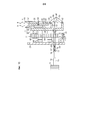
Фиг. 1 представляет собой вид спереди, показывающий участок намоточного устройства в соответствии с первым вариантом осуществления;FIG. 1 is a front view showing a portion of a coiler in accordance with the first embodiment;
Фиг. 2 представляет собой увеличенный продольный разрез, показывающий намоточное устройство первого варианта осуществления;FIG. 2 is an enlarged longitudinal section showing the winding device of the first embodiment;
Фиг. 3 представляет собой увеличенный вид сверху, показывающий намоточное устройство первого варианта осуществления;FIG. 3 is an enlarged top view showing the winding device of the first embodiment;
Фиг. 4 представляет собой увеличенный разрез, показывающий намоточный участок намоточного устройства первого варианта осуществления, показанного на Фиг. 2;FIG. 4 is an enlarged sectional view showing the winding portion of the winding device of the first embodiment shown in FIG. 2;
Фиг. 5 представляет собой увеличенный вид спереди, показывающий многозвенный механизм намоточного устройства первого варианта осуществления;FIG. 5 is an enlarged front view showing the multi-link winding mechanism of the first embodiment;
Фиг. 6 представляет собой разрез, показывающий участок намоточного устройства Фиг. 2 в рабочем состоянии;FIG. 6 is a sectional view showing the portion of the winding device of FIG. 2 in working condition;
Фиг. 7 представляет собой вид спереди, показывающий участок намоточного устройства в соответствии со вторым вариантом осуществления;FIG. 7 is a front view showing a portion of a coiler in accordance with a second embodiment;
Фиг. 8 представляет собой увеличенный продольный разрез, показывающий участок намоточного устройства второго варианта осуществления;FIG. 8 is an enlarged longitudinal section showing a portion of the winding device of the second embodiment;
Фиг. 9 представляет собой разрез, показывающий участок намоточного устройства Фиг. 8 в состоянии, в котором диаметр наматывания изменен; иFIG. 9 is a sectional view showing the portion of the winding device of FIG. 8 in a state in which the winding diameter is changed; and
Фиг. 10 представляет собой разрез, показывающий участок намоточного устройства Фиг. 8 в рабочем состоянии.FIG. 10 is a sectional view showing a portion of the winding device of FIG. 8 in working condition.
ВАРИАНТЫ ОСУЩЕСТВЛЕНИЯ ИЗОБРЕТЕНИЯEMBODIMENTS OF THE INVENTION
Первый вариант осуществленияThe first version of the implementation
Намоточное устройство в соответствии с первым вариантом осуществления настоящего изобретения теперь будет описываться со ссылкой на Фиг. 1-6.A sweeping device in accordance with the first embodiment of the present invention will now be described with reference to FIG. 1-6.
Как показано на Фиг. 1-3, вращательный вал 22 поддерживается с возможностью вращения рамой 21 устройства и вращается посредством непоказанного двигателя. Дискообразная базовая плита 23 прикреплена к дистальному концу вращательного вала 22. Сегменты 25 размещены в кольцевой зоне (не показана), соответствующей внешней окружности базовой плиты 23. Каждый из сегментов 25 имеет форму, соответствующую одной из форм, полученных посредством разделения кольцевой зоны на множество (в первом варианте осуществления, четыре) секций вдоль окружности базовой плиты. Каждый из сегментов 25 поддерживается базовой плитой 23 таким образом, чтобы быть подвижным в радиальном направлении базовой плиты 23 вокруг вращательного вала 22. Когда вращательный вал 22 вращает базовую плиту 23 в одном направлении, проволока W наматывается на внешнюю окружность сегментов 25 для образования бортового кольца В.As shown in FIG. 1-3, the
Вал 26 манипулирования, проходящий в радиальном направлении базовой плиты 23, поддерживается передней поверхностью базовой плиты 23 вращательным образом вокруг оси вала 26 манипулирования. Червячное колесо 27 прикреплено к первому концу вала 26 манипулирования. Рукояточный вал 28, проходящий вдоль оси вращательного вала 22, поддерживается передней поверхностью базовой плиты 23 вблизи первого конца вала 26 манипулирования вращательным образом вокруг оси рукояточного вала 28. Червяк 29, который зацепляется с червячным колесом 27, образован в рукояточном вале 28. Крепежный участок 28а, в которому съемно прикрепляется рукоятка 30, образован на дистальном конце рукояточного вала 28.The
Механизм 31 преобразования для преобразования вращения вала 26 манипулирования в радиальное движение сегментов 25 размещен между валом 26 манипулирования и сегментом 25. Когда рукоятка 30, которая прикреплена к крепежному участку 28а рукояточного вала 28, манипулируется для вращения рукояточного вала 28, вал 26 манипулирования вращается посредством червяка 29 и червячного колеса 27. Механизм 31 преобразования перемещает сегменты 25 в радиальном направлении базовой плиты 23 в ответ на вращение вала 26 манипулирования.The
Конфигурация механизма 31 преобразования теперь будет подробно описываться. Со ссылкой на Фиг. 1-3, утолщенный участок 23а для фиксации вращательного вала 22 образован в передней поверхности базовой плиты 23. Первое зубчатое колесо 34, которое представляет собой коническое зубчатое колесо, поддерживается внешней окружностью утолщенного участка 23а базовой плиты 23 вращательным образом относительно вращательного вала 22 с помощью радиального подшипника 35 и упорного подшипника 36. Второе зубчатое колесо 37, которое представляет собой коническое зубчатое колесо, прикреплено ко второму концу вала 26 манипулирования таким образом, чтобы зацепляться с первым зубчатым колесом 34. Множество (в первом варианте осуществления, четыре) резьбовых вала 38, каждый из которых проходит в радиальном направлении базовой плиты 23, поддерживается передней поверхностью базовой плиты 23 в положениях, соответствующих сегментам 25, вращательным образом вокруг оси каждого резьбового вала 38. Третье зубчатое колесо 39, которое представляет собой коническое зубчатое колесо, зацепляющееся с первым зубчатым колесом 34, прикреплено к внутреннему концевому участку каждого резьбового вала 38.The configuration of the
Пара рельсообразных направляющих участков 40, каждый из которых проходит в радиальном направлении базовой плиты 23, обеспечена на передней поверхности базовой плиты 23 в положении, соответствующем резьбовым валам 38. Множество подвижных элементов 41, которое поддерживает сегменты 25, поддерживается с возможностью перемещения соответствующими направляющими участками 40. Внутренний резьбовой участок 42, который закручивается на соответствующий резьбовой вал 38, образован на задней поверхности каждого из подвижных элементов 41 выступающим назад образом. Когда рукоятка 30 манипулируется для вращения вала 26 манипулирования, резьбовые валы 38 вращаются посредством соответствующих вторых зубчатых колес 37, первых зубчатых колес 34 и третьих зубчатых колес 39. Такое вращение резьбовых валов 38 перемещает подвижные элементы 41 вместе с сегментами 25 посредством внутренних резьбовых участков 42, каждый в радиальном направлении базовой плиты 23. Таким образом, диаметр наматывания бортового кольца В изменяется.A pair of rail-shaped
Каждый из подвижных элементов 41 образован плоским корпусом 43, который направляется посредством соответствующего направляющего участка 40 на базовой плите 23, и плоским поддерживающим элементом 45. Каждый из поддерживающих элементов 45 поддерживается соответствующим одним из корпусов 43 подвижным образом в радиальном направлении базовой плиты 23 посредством пары рельсообразных направляющих участков 44, которая образована на передней поверхности корпуса 43. Множество канавкообразных поддерживающих участков 46 образовано в передней поверхности каждого поддерживающего элемента 45 и разнесено на заданные интервалы в радиальном направлении базовой плиты 23. Пара резьбовых отверстий 47 образована в передней поверхности поддерживающего элемента 45 в положении между каждой соседней парой поддерживающих участков 46 в окрестностях противоположных сторон поддерживающего элемента 45. Как будет описываться ниже, каждый сегмент 25 сцепляется с одним из поддерживающих участков 46 соответствующего поддерживающего элемента 45, выбранным для обеспечения требуемого диаметра наматывания и, таким образом, поддерживается поддерживающим элементом 45.Each of the
Конфигурация каждого сегмента 25 будет подробно описываться в дальнейшем. Как показано на Фиг. 1-3 и 4, каждый сегмент 25 образован крепежным участком 50, который поддерживается соответствующим поддерживающим элементом 45, и намоточным участком 52, который съемно прикрепляется к крепежному участку 50 с помощью множества винтов 51. Выступающий сцепляющий участок 53, который выборочно сцепляется с одним из поддерживающих участков 46 поддерживающего элемента 45, образован на внутреннем периферийном конце крепежного участка 50. Когда сцепляющий участок 53 крепежного участка 50 выборочно сцепляется с одним из поддерживающих участков 46 поддерживающего элемента 45, пара винтов 54 закручивается в соответствующие резьбовые отверстия 47 поддерживающего элемента 45 сверху крепежного участка 50. Посредством извлечения винтов 54 и сцепления сцепляющего участка 53 с другим одним из поддерживающих участков 46, положение сегмента 25 на поддерживающем элементе 45 регулируется в радиальном направлении базовой плиты 23.The configuration of each
Как показано на Фиг. 1 и 2, намоточный участок 52 каждого сегмента 25 образован корпусным участком 55, который проходит с дугообразной формой, как видно спереди, и регулировочным участком 56. Каждый из регулировочных участков 56 прикреплен к радиально внешней стороне соответствующего корпусного участка 55 и имеет дугообразную форму, как видно спереди. Каждый корпусной участок 55 имеет, по существу, Т-образное сечение с головным участком, обращенным вперед. Каждый регулировочный участок 56 включает в себя множество щелей 56а, каждая из которых проходит через регулировочный участок 56 и проходит в направлении вперед-назад. Регулировочный участок 56 прикрепляется к корпусному участку 55 с помощью винтов 57, которые закручиваются в соответствующие резьбовые отверстия корпусного участка 55 через щели 56а. Эта конструкция обеспечивает возможность регулирования положения регулировочного участка 56 относительно корпусного участка 55 в осевом направлении вращательного вала 22, или, другими словами, в направлении протяженности каждой щели 56а. Ссылаясь на Фиг. 4, канавка 58 для наматывания проволоки W образована между корпусным участком 55 и регулировочным участком 56 намоточного участка 52. Ширина L1 канавки 58 изменяется посредством регулирования положения регулировочного участка 56 относительно корпусного участка 55. Это изменяет ширину наматывания бортового кольца В.As shown in FIG. 1 and 2, the winding
Со ссылкой на Фиг. 1, 2 и 5, многозвенный механизм 61 для поддерживания каждого поддерживающего элемента 45, размещен на корпусе 43 соответствующего подвижного элемента 41. Многозвенный механизм 61 образован первым звеном 63, вторым звеном 65 и соединительным пальцем 66. Первое звено 63 поддерживается с возможностью поворота внутренним концевым участком корпуса 43 с помощью первого поддерживающего пальца 62. Второе звено 65 поддерживается с возможностью поворота внутренним концевым участком поддерживающего элемента 45 с помощью второго поддерживающего пальца 64. Соединительный палец 66 соединяет с возможностью поворота первое звено 63 и второе звено 65 друг с другом.Referring to FIG. 1, 2 and 5, the
Как показано на Фиг. 1, 2 и 6, блокирующий механизм 67 для блокировки каждого многозвенного механизма 61 в блокировочном положении Р1 размещен в корпусе 43 соответствующего подвижного элемента 41. Базовая плита 23 имеет множество вытянутых отверстий 68, проходящих на противоположных сторонах резьбового вала 38. Вытянутые отверстия 68 образованы таким образом, чтобы проходить через базовую плиту 23. Каждый из блокирующих механизмов 67 включает в себя пару поддерживающих труб 69 и пару стержней 70. Поддерживающие трубы 69 проходят через два соответствующих вытянутых отверстия 68 на противоположных сторонах соответствующего резьбового вала 38 и проходят в осевом направлении вращательного вала 22. Каждая из поддерживающих труб 69 имеет передний конец, прикрепленный к корпусу 43. Каждый из стержней 70 вставляется через соответствующие поддерживающие трубы 69 подвижным образом. Каждый блокирующий механизм 67 дополнительно включает в себя пару блокировочных рычагов 71 и пару пружин 72. Блокировочные рычаги 71 функционально соединяют передние концы стержней 70 с концевыми участками соединительного пальца 66 многозвенного механизма 61. Каждая из пружин 72 размещена между задним концом соответствующей поддерживающей трубы 69 и задним концом соответствующего стержня 70. Стопор 73, который ограничивает направленное назад перемещение второго звена 65 каждого многозвенного механизма 61, образован на корпусе 43 одного из подвижных элементов 41 выступающим вперед образом.As shown in FIG. 1, 2 and 6, the
В нормальном состоянии, со ссылкой на Фиг. 1 и 2, пружины 72 побуждают соединительный палец 66 соответствующего многозвенного механизма 61 перемещаться по направлению к базовой плите 23 посредством стержня 70 и блокировочного рычага 71. Таким образом, первое звено 63 и второе звено 65 многозвенного механизма 61 побуждаются поворачиваться по направлению к базовой плите 23 вокруг первого и второго поддерживающих пальцев 62, 64. Стопор 73 сцепляется со вторым звеном 65 для ограничения направленного назад перемещения второго звена 65 в положении, где ось соединительного пальца 66 располагается незначительно позади мертвой точки, которая размещена на линии, соединяющей ось первого поддерживающего пальца 62 с осью второго поддерживающего пальца 64. В дальнейшем, это положение будет называться блокировочным положением Р1. Когда размещен в блокировочном положении Р1, первое звено 63 и второе звено 65 многозвенного механизма 61 блокируются в состоянии, препятствующем поворачиванию. Это предотвращает перемещение оси соединительного пальца 66 назад относительно блокировочного положения Р1, таким образом предохраняя поддерживающий элемент 45 подвижного элемента 41, который поддерживает сегмент 25, от перемещения радиально внутрь.In the normal state, with reference to FIG. 1 and 2, the
Как показано на Фиг. 2 и 6, разблокирующие механизмы 74, каждый из которых разблокирует соответствующий многозвенный механизм 61 посредством блокирующего механизма 67, размещены в раме 21 устройства. Каждый из разблокирующих механизмов 74 образован цилиндром 75, в котором размещается поршневой стержень. Толкающий участок 76, который является сцепляемым с задним концом стержня 70 соответствующего блокирующего механизма 67, образован на переднем конце поршневого стержня цилиндра 75.As shown in FIG. 2 and 6, the unlocking
После завершения наматывания проволоки W в канавки 58, образованные на внешней окружности сегментов 25, или, другими словами, когда бортовое кольцо В полностью образовано, базовая плита 23 останавливается в заданном положении. На этом этапе, задние концы стержней 70 блокирующих механизмов 67 размещены таким образом, чтобы соответствовать толкающим участками 76 разблокирующих механизмов 74. В этом состоянии, цилиндры 75 приводятся в действие таким образом, чтобы выдвигать поршневые стержни так, что, ссылаясь на Фиг. 6, стержни 70 толкаются вперед посредством толкающих участков 76. Таким образом, стержни 70 перемещают соединительные пальцы 66 многозвенных механизмов 61 от базовой плиты 23 посредством блокировочных рычагов 71, таким образом размещая соединительные пальцы 66 на расстоянии от блокировочных положений Р1. Это разблокирует первые звенья 63 и вторые звенья 65 многозвенных механизмов 61 из заблокированного состояния таким образом, что поддерживающие элементы 45 подвижных элементов 41, которые поддерживают сегменты 25, перемещаются радиально внутрь. Бортовое кольцо В таким образом отделяется от канавок 58.After winding the wire W into the
Работа намоточного устройства, выполненного, как описано выше, теперь будет описываться.The operation of the winding device, performed as described above, will now be described.
В состоянии, показанном на Фиг. 1 и 2, каждый блокирующий механизм 67 блокирует первое звено 63 и второе звено 65 соответствующего многозвенного механизма 61 в блокировочном положении Р1. Поддерживающий элемент 45 каждого подвижного элемента 41, который поддерживает соответствующий сегмент 25, таким образом, удерживается так, чтобы не перемещаться радиально внутрь. В этом состоянии, когда вращательный вал 22 вращает базовую плиту 23 в одном направлении, проволока W наматывается в канавки 58, которые образованы на внешней окружности соответствующих сегментов 25, накладывающимся друг на друга образом в направлении наслоения в состоянии, выровненном в направлении ряда. В результате, образуется бортовое кольцо В.In the state shown in FIG. 1 and 2, each blocking
Когда базовая плита 23 останавливается в заданном положении после полного образования бортового кольца В, задние концы стержней 70 блокирующих механизмов 67 размещаются таким образом, чтобы соответствовать толкающим участкам 76 разблокирующих механизмов 74. В этом состоянии, поршневые стержни цилиндров 75 разблокирующих механизмов 74 выдвигаются, таким образом разблокируя первые звенья 63 и вторые звенья 65 многозвенных механизмов 61 из заблокированных состояний в блокировочных положениях Р1, как показано на Фиг. 6. Это перемещает поддерживающие элементы 45 подвижных элементов 41, которые поддерживают сегменты 25, радиально внутрь, таким образом отделяя бортовое кольцо В от канавок 58. Таким образом, бортовое кольцо В легко снимается с сегментов 25.When the
Для регулирования диаметра наматывания бортового кольца В, которое образуется на сегментах 25, рукоятка 30 прикрепляется к крепежному участку 28а рукояточного вала 28. Рукоятка 30 затем манипулируется для вращения рукояточного вала 28. Это вращает вал 26 манипулирования посредством червяка 29 и червячного колеса 27, таким образом, перемещая подвижные элементы 41, поддерживающие сегменты 25, в радиальном направлении базовой плиты 23 посредством механизмов 31 преобразования посредством вращения вала 26 манипулирования. Таким образом, сегменты 25 радиально перемещаются для изменения диаметра наматывания бортового кольца В, которое образуется в канавках 58 на внешней окружности сегментов 25. Соответственно, даже если требуется регулировать диаметр наматывания на незначительную величину, диаметр наматывания бортового кольца В точно регулируется на необходимую величину в соответствии с величиной манипулирования рукоятки 30.To regulate the winding diameter of the side ring B, which is formed on the
Если диаметр наматывания бортового кольца В, которое образуется на сегментах 25, должен изменяться на большую величину, регулирование посредством рукоятки 30 не выполняется, и положения сегментов 25 относительно поддерживающих элементов 45 изменяются, как показано пунктирными линиями на Фиг. 2. Положения сегментов 25 относительно поддерживающих элементов 45 изменяются посредством сцепления сегментов 25 с другими поддерживающими участками 46 поддерживающих элементов 45. Положения сегментов 25, которые размещаются вдоль окружности базовой плиты 23, таким образом, изменяются в радиальном направлении базовой плиты 23. Таким образом, диаметр наматывания бортового кольца В изменяется дискретно.If the winding diameter of the side ring B, which is formed on the
Когда ширина наматывания бортового кольца В, образованного на сегментах 25, должна изменяться, положение регулировочного участка 56 намоточного участка 52 каждого сегмента 25 регулируется, как показано на Фиг. 4. Винты 57 ослабляются и, в этом состоянии, регулировочный участок 56 перемещается назад или вперед в осевом направлении вращательного вала 22 относительно корпусного участка 55. Это увеличивает или уменьшает ширину L1 канавки 58, которая образована между корпусным участком 55 и регулировочным участком 56. В результате, ширина наматывания бортового кольца В изменяется.When the winding width of the bead ring B formed on the
Также, когда форма поперечного сечения бортового кольца В, образованного на сегментах 25, должна изменяться, намоточный участок 52 снимается с крепежного участка 50 каждого сегмента 25 и заменяется намоточным участком 52, который выполнен с возможностью образования требуемого бортового кольца В. Таким образом, как будет описано ниже во втором варианте осуществления, форма поперечного сечения бортового кольца В может меняться на шестиугольную форму.Also, when the cross-sectional shape of the side ring B formed on the
Первый вариант осуществления имеет следующие преимущества.The first embodiment has the following advantages.
(1) В намоточном устройстве первого варианта осуществления, множество сегментов 25 размещено вдоль окружности базовой плиты 23, которая вращается посредством вращательного вала 22. Каждый из сегментов 25 поддерживается базовой плитой 23 образом, подвижным в радиальном направлении базовой плиты 23 вокруг вращательного вала 22. Каждый сегмент 25 имеет форму, соответствующую одной из форм, полученных посредством разделения кольцевого корпуса, проходящего вдоль окружности базовой плиты 23, на множество секций. Проволока W наматывается на внешнюю окружность сегментов 25 для образования бортового кольца В. Каждый механизм 31 преобразования обеспечен между валом 26 манипулирования, который вращается посредством рукоятки 30, и соответствующим сегментом 25. Механизм 31 преобразования выполнен с возможностью преобразования вращения вала 26 манипулирования в радиальное движение сегмента 25.(1) In the winding device of the first embodiment, a plurality of
Соответственно, когда вал 26 манипулирования вращается посредством рукоятки 30, механизмы 31 преобразования радиально перемещают сегменты 25, при этом сегменты 25 размещаются вдоль окружности базовой плиты 23. Это изменяет диаметр наматывания бортового кольца В. В результате, посредством такого простого манипулирования, которое представляет собой вращение рукоятки 30, диаметр наматывания бортового кольца В легко изменяется независимо от того, изменяется ли он на незначительную величину или значительную величину.Accordingly, when the manipulating
(2) В намоточном устройстве первого варианта осуществления, каждый механизм 31 преобразования образован первым зубчатым колесом 34, вторым зубчатым колесом 37, резьбовым валом 38, третьим зубчатым колесом 39 и подвижным элементом 41. Первое зубчатое колесо 34 поддерживается вращательным образом относительно вращательного вала 22. Второе зубчатое колесо 37 прикреплено к валу 26 манипулирования таким образом, чтобы зацепляться с первым зубчатым колесом 34. Резьбовой вал 38 поддерживается базовой плитой 23. Третье зубчатое колесо 39 прикреплено к резьбовому валу 38 таким образом, чтобы зацепляться с первым зубчатым колесом 34. Подвижный элемент 41 направляется посредством направляющего участка 40, который проходит в радиальном направлении базовой плиты 23, и включает в себя внутренний резьбовой участок 42, закручивающийся на резьбовой вал 38. Подвижный элемент 41 поддерживает соответствующий сегмент 25. Для изменения диаметра наматывания бортового кольца В, рукоятка 30 вращается для побуждения механизмов 31 преобразования, каждый из которых включает в себя зубчатые колеса 34, 37, 39, радиально перемещать сегменты 25 в состоянии с размещением вдоль окружности.(2) In the winding device of the first embodiment, each
(3) В намоточном устройстве первого варианта осуществления, каждый подвижный элемент 41 образован корпусом 43, который направляется посредством направляющего участка 40, и поддерживающим элементом 45. Поддерживающий элемент 45 поддерживается корпусом 43 образом, подвижным в радиальном направлении базовой плиты 23, и поддерживает соответствующий сегмент 25. После полного образования бортового кольца В на сегментах 25, поддерживающие элементы 45 перемещаются в радиальном направлении базовой плиты 23 относительно корпусов 43. Сегменты 25, таким образом, отделяются от внутренней периферийной поверхности бортового кольца В таким образом, что бортовое кольцо В легко снимается.(3) In the winding device of the first embodiment, each
(4) В намоточном устройстве первого варианта осуществления, каждый сегмент 25 образован крепежным участком 50, который поддерживается поддерживающим элементом 45, и намоточным участком 52, который съемно прикрепляется к крепежному участку 50. Канавки 58 для образования бортового кольца В образованы в намоточных участках 52. Множество типов намоточных участков 52 с канавками 58, имеющими разные формы поперечного сечения, могут подготавливаться для обеспечения возможности изменения формы поперечного сечения целевого бортового кольца В посредством снятия намоточных участков 52 с крепежного участка 50 и замены намоточных участков 52.(4) In the winding device of the first embodiment, each
(5) Намоточное устройство первого варианта осуществления выполнено таким образом, что ширина L1 канавок 58 является изменяемой. Соответственно, посредством регулирования ширины L1 канавок 58, ширина наматывания целевого бортового кольца В может изменяться.(5) The winding device of the first embodiment is configured such that the width L1 of the
(6) В намоточном устройстве первого варианта осуществления, каждый поддерживающий элемент 45 имеет множество поддерживающих участков 46, которые проходят перпендикулярно относительно резьбового вала 38 и выровнены в радиальном направлении базовой плиты 23. Каждый сегмент 25 поддерживается одним из поддерживающих участков 46. Соответственно, радиальное положение каждого сегмента 25 изменяется посредством изменения положения сегмента 25 на положение, где сегмент 25 поддерживается одним из поддерживающих участков 46 поддерживающего элемента 45, выбранным для обеспечения требуемого диаметра наматывания. В результате, диаметр наматывания бортового кольца В изменяется на большую величину.(6) In the winding device of the first embodiment, each supporting
(7) Намоточное устройство первого варианта осуществления включает в себя многозвенные механизмы 61, которые поддерживают поддерживающие элементы 45, и блокирующие механизмы 67, которые блокируют многозвенные механизмы 61 в блокировочном положении Р1. Рама 21 устройства включает в себя разблокирующие механизмы 74, которые разблокируют блокирующие механизмы 67. Соответственно, в нормальном состоянии, блокирующие механизмы 67 блокируют многозвенные механизмы 61 в блокировочном положении Р1 для удерживания поддерживающих элементов 45, которые поддерживают сегмент 25, так, чтобы не перемещаться радиально внутрь. Это обеспечивает возможность стабильного наматывания проволоки W на сегменты 25. В противоположность, после полного образования бортового кольца В, разблокирующие механизмы 74 разблокируют многозвенные механизмы 61, и поддерживающие элементы 45 перемещаются радиально внутрь. Это отделяет сегменты 25 от внутренней периферийной поверхности бортового кольца В, таким образом обеспечивая возможность легкого снятия бортового кольца В.(7) The winding device of the first embodiment includes the
Второй вариант осуществленияSecond Embodiment
Намоточное устройство в соответствии со вторым вариантом осуществления настоящего изобретения теперь будет описываться. Главным образом, будут рассматриваться отличия от первого варианта осуществления.Winding device in accordance with the second embodiment of the present invention will now be described. Mainly, differences from the first embodiment will be considered.
Во втором варианте осуществления, как показано на Фиг. 7-10, крепежный участок 50 каждого сегмента 25 имеет два вытянутых отверстия 81, при этом каждое проходит в осевом направлении резьбового вала 38. Винты 54 вкручиваются в поддерживающий элемент 45 соответствующего подвижного элемента 41 через вытянутые отверстия 81. Таким образом, крепежный участок 50 сегмента 25 поддерживается посредством поддерживающего элемента 45 таким образом, что положение крепежного участка 50 является регулируемым относительно поддерживающего элемента 45 в радиальном направлении базовой плиты 23. Ступенчатый участок 82, который выступает вперед, образован на внутреннем периферийном конце передней поверхности каждого поддерживающего элемента 45. Распорка 83 для задания радиального положения соответствующего сегмента 25 обеспечена между ступенчатым участком 82 и крепежным участком 50 сегмента 25.In the second embodiment, as shown in FIG. 7-10, the
Подготовлено множество типов распорок 83, имеющих разные толщины (разные размеры в радиальном направлении базовой плиты 23). Со ссылкой на Фиг. 8 и 9, радиальное положение каждого сегмента 25 изменяется посредством размещения выбранной одной из распорок 83 между ступенчатым участком 82 соответствующего поддерживающего элемента 45 и крепежным участком 50 сегмента 25. Таким образом, диаметр наматывания бортового кольца В, которое образуется в канавках 58, образованных на внешних окружностях сегментов 25, изменяется на значительную величину.Prepared many types of
Также, во втором варианте осуществления, диаметр наматывания бортового кольца В регулируется посредством механизмов 31 преобразования, как в первом варианте осуществления. Когда вал 26 манипулирования вращается посредством манипулирования рукоятки 30, механизмы 31 преобразования, которые включают в себя зубчатые колеса 34, 37, 39, перемещают сегменты 25 в радиальном направлении базовой плиты 23. Диаметр наматывания бортового кольца В, таким образом, легко регулируется даже на незначительную величину регулирования. Более того, как в первом варианте осуществления, второй вариант осуществления включает в себя многозвенные механизмы 61, блокирующие механизмы 67 и разблокирующие механизмы 74. Со ссылкой на Фиг. 8, каждый многозвенный механизм 61 и соответствующий блокирующий механизм 67 блокируют поддерживающий элемент 45, который поддерживает сегмент 25, таким образом, что поддерживающий элемент 45 не перемещается радиально внутрь. Это обеспечивает стабильное образование бортового кольца В на сегментах 25. Ссылаясь на Фиг. 10, каждый разблокирующий механизм 74 разблокирует соответствующий поддерживающий элемент 45 таким образом, что сегмент 25 перемещается радиально внутрь для обеспечения легкого снятия бортового кольца В с сегментов 25.Also, in the second embodiment, the winding diameter of the side ring B is adjusted by
Дополнительно к преимуществам (1)-(5) и (7) первого варианта осуществления, второй вариант осуществления обеспечивает следующее преимущество.In addition to the advantages (1) to (5) and (7) of the first embodiment, the second embodiment provides the following advantage.
(8) Во втором варианте осуществления, каждый сегмент 25 поддерживается посредством соответствующего поддерживающего элемента 45 таким образом, что положение сегмента 25 является регулируемым относительно поддерживающего элемента 45 в радиальном направлении базовой плиты 23. Распорка 83 размещается между сегментом 25 и поддерживающим элементом 45 для регулирования радиального положения сегмента 25. Соответственно, радиальное положение сегмента 25 изменяется посредством выбора подходящей одной из множества типов распорок 83, имеющих разные толщины, и размещения выбранной распорки 83 между сегментом 25 и поддерживающим элементом 45. В результате, диаметр наматывания бортового кольца В изменяется на соответствующую величину.(8) In the second embodiment, each
МодификацииModifications
Показанные варианты осуществления могут быть модифицированы, как описано ниже.The embodiments shown are modified as described below.
- В первом и втором вариантах осуществления, каждый сегмент 25 имеет форму, соответствующую одной из форм, полученных посредством разделения кольцевого корпуса, который может размещаться соосно с базовой плитой в окрестности внешней окружности базовой плиты 23, на четыре секции. Однако, сегмент 25 может иметь форму, соответствующую одной из форм, полученных посредством разделения кольцевого корпуса на две, три, пять или более секций.- In the first and second embodiments, each
- Может быть опущена конфигурация, включающая в себя множество поддерживающих участков 46, которые являются сцепляемыми с сегментами 25 для дискретного изменения диаметра наматывания.- A configuration may be omitted that includes a plurality of supporting
- В первом и втором вариантах осуществления, когда положение каждого сегмента 25 изменяется в радиальном направлении базовой плиты 23 на значительную величину, например, поддерживающее положение сегмента 25 переключается из положения, соответствующего поддерживающему участку 46, рядом со вторым поддерживающим пальцем 64, на положение, соответствующее поддерживающему участку 46 в окрестности внешнего конца поддерживающего элемента 45, может быть необходимым заменить сегмент 25 сегментом 25, имеющим намоточный участок 52 с другим радиусом кривизны. Для удовлетворения такой необходимости, множество типов сегментов 25 с намоточными участками 52, имеющими разные радиусы кривизны, могут подготавливаться и заменяться, когда необходимо. В противоположность, если величина изменения положения каждого сегмента 25 не является существенно большой, например, сегмент 25 переключается из сцепления с определенным одним из поддерживающих участков 46 в сцепление с соседним одним из поддерживающих участков 46 в поддерживающем элементе 45, замена сегментов 25 является ненужной.- In the first and second embodiments, when the position of each
ОПИСАНИЕ ССЫЛОЧНЫХ ПОЗИЦИЙDESCRIPTION OF REFERENCE POSITIONS
21 рама устройства,21 device frames
22 вращательный вал,22 rotary shaft
23 базовая плита,23 base plate,
25 сегмент,25 segment
26 вал манипулирования,26 shaft manipulation
28 рукояточный вал,28 handle shaft,
30 рукоятка,30 handle
31 механизм преобразования,31 conversion mechanism
34 первое зубчатое колесо,34 first gear,
37 второе зубчатое колесо,37 second gear,
38 резьбовой вал,38 threaded shaft
39 третье зубчатое колесо,39 third gear,
40 направляющий участок,40 guiding section,
41 подвижный элемент,41 movable element
42 внутренний резьбовой участок,42 internal thread area
43 корпус,43 building
45 поддерживающий элемент,45 supporting element
46 поддерживающий участок,46 supporting area
50 крепежный участок,50 mounting area
52 намоточный участок,52 winding section,
53 сцепляющий участок,53 coupling portion,
55 корпусной участок,55 enclosure area
56 регулировочный участок,56 adjustment area
58 канавка,58 groove,
61 многозвенный механизм,61 multi-link mechanism
63 первое звено,63 first link
65 второе звено,65 second link
66 соединительный палец,66 connecting finger
67 блокирующий механизм,67 blocking mechanism
70 стержень,70 rod,
71 блокирующий рычаг,71 locking lever
72 пружина,72 spring,
73 стопор,73 stopper,
74 разблокирующий механизм,74 unlocking mechanism
75 цилиндр,75 cylinder,
83 распорка,83 strut,
W проволока,W wire,
В бортовое кольцо,In the side ring,
L1 ширина канавки,L1 groove width
Р1 блокировочное положение.P1 blocking position.
Claims (28)
Applications Claiming Priority (1)
| Application Number | Priority Date | Filing Date | Title |
|---|---|---|---|
| PCT/JP2012/066006 WO2013190696A1 (en) | 2012-06-22 | 2012-06-22 | Winding device |
Publications (3)
| Publication Number | Publication Date |
|---|---|
| RU2015101513A RU2015101513A (en) | 2016-08-10 |
| RU2607752C2 RU2607752C2 (en) | 2017-01-10 |
| RU2607752C9 true RU2607752C9 (en) | 2019-07-18 |
Family
ID=49768325
Family Applications (1)
| Application Number | Title | Priority Date | Filing Date |
|---|---|---|---|
| RU2015101513A RU2607752C9 (en) | 2012-06-22 | 2012-06-22 | Winding device |
Country Status (9)
| Country | Link |
|---|---|
| US (2) | USRE48521E1 (en) |
| JP (1) | JP6013478B2 (en) |
| KR (1) | KR101814866B1 (en) |
| CN (1) | CN104395062B (en) |
| DE (1) | DE112012006569B4 (en) |
| IN (1) | IN2014MN02541A (en) |
| PH (1) | PH12014502818A1 (en) |
| RU (1) | RU2607752C9 (en) |
| WO (1) | WO2013190696A1 (en) |
Families Citing this family (7)
| Publication number | Priority date | Publication date | Assignee | Title |
|---|---|---|---|---|
| FR3009233B1 (en) * | 2013-08-01 | 2016-01-01 | Michelin & Cie | DRUM FOR TREATING A TREAD WITH MOBILE SECTORS |
| US20170106617A1 (en) * | 2015-10-14 | 2017-04-20 | Bartell Machinery Systems, L.L.C. | Quick-change bead former |
| EP3362272B1 (en) | 2015-10-14 | 2020-11-18 | Bartell Machinery Systems LLC | Multi-step bead former |
| IT201600070333A1 (en) * | 2016-07-06 | 2018-01-06 | Bridgestone Europe Nv | ROTARY DRUM WITH FACILITATED COLLECTION FOR THE FORMATION OF A HEEL OF A TIRE |
| IT201600070310A1 (en) * | 2016-07-06 | 2018-01-06 | Bridgestone Europe Nv | ROTARY DRUM WITH QUICK DISASSEMBLY FOR THE FORMATION OF A HEEL OF A TIRE |
| JP6855694B2 (en) * | 2016-07-08 | 2021-04-07 | 住友ゴム工業株式会社 | Former for bead core formation |
| JP6801285B2 (en) * | 2016-08-08 | 2020-12-16 | 住友ゴム工業株式会社 | Bead core manufacturing equipment |
Citations (5)
| Publication number | Priority date | Publication date | Assignee | Title |
|---|---|---|---|---|
| SU1353663A1 (en) * | 1986-07-02 | 1987-11-23 | Всесоюзный Научно-Исследовательский И Конструкторский Институт По Оборудованию Для Шинной Промышленности | Machine for making bead rings |
| SU1627418A1 (en) * | 1988-08-31 | 1991-02-15 | Научно-исследовательский институт шинной промышленности | Templet for winding bead rings |
| JPH09267410A (en) * | 1996-04-02 | 1997-10-14 | Tokyo Seiko Co Ltd | Bead molding machine and wire like material winding apparatus |
| US6352602B1 (en) * | 1998-04-07 | 2002-03-05 | Bridgestone Corporation | Bead wire winding device and winding method |
| JP2007160830A (en) * | 2005-12-16 | 2007-06-28 | Bridgestone Corp | Forming apparatus for polygonal bead core for pneumatic tire |
Family Cites Families (10)
| Publication number | Priority date | Publication date | Assignee | Title |
|---|---|---|---|---|
| US1821161A (en) * | 1930-03-18 | 1931-09-01 | Mason Tire & Rubber Corp | Bead forming machine |
| US2049587A (en) * | 1935-01-15 | 1936-08-04 | Us Rubber Co | Method and apparatus for making coils |
| US3051221A (en) * | 1958-11-24 | 1962-08-28 | Nat Standard Co | Former for bead building machines or the like |
| CN2042851U (en) | 1988-09-17 | 1989-08-16 | 任朝理 | Horizontal auto winding-unwinding unit by collectitive driving |
| JP2552005B2 (en) | 1989-09-29 | 1996-11-06 | 富士通株式会社 | Display device |
| JPH03118630U (en) * | 1990-03-22 | 1991-12-06 | ||
| JP4342033B2 (en) | 1999-05-26 | 2009-10-14 | 株式会社ブリヂストン | Winding former |
| CN2574804Y (en) | 2002-09-30 | 2003-09-24 | 湖南宇晶机器实业有限公司 | Internal composite type crystallizer |
| CN200995916Y (en) | 2006-12-31 | 2007-12-26 | 中冶南方工程技术有限公司 | Belt winding aid |
| CN101058235A (en) | 2007-06-01 | 2007-10-24 | 昊华南方(桂林)橡胶有限责任公司 | Hexagonal wired ring winding production line |
-
2012
- 2012-06-22 CN CN201280074045.2A patent/CN104395062B/en active Active
- 2012-06-22 IN IN2541MUN2014 patent/IN2014MN02541A/en unknown
- 2012-06-22 JP JP2014521181A patent/JP6013478B2/en active Active
- 2012-06-22 RU RU2015101513A patent/RU2607752C9/en active
- 2012-06-22 KR KR1020147036485A patent/KR101814866B1/en active IP Right Grant
- 2012-06-22 WO PCT/JP2012/066006 patent/WO2013190696A1/en active Application Filing
- 2012-06-22 DE DE112012006569.7T patent/DE112012006569B4/en active Active
- 2012-06-22 US US16/392,545 patent/USRE48521E1/en active Active
- 2012-06-22 US US14/409,327 patent/US9630370B2/en not_active Ceased
-
2014
- 2014-12-17 PH PH12014502818A patent/PH12014502818A1/en unknown
Patent Citations (5)
| Publication number | Priority date | Publication date | Assignee | Title |
|---|---|---|---|---|
| SU1353663A1 (en) * | 1986-07-02 | 1987-11-23 | Всесоюзный Научно-Исследовательский И Конструкторский Институт По Оборудованию Для Шинной Промышленности | Machine for making bead rings |
| SU1627418A1 (en) * | 1988-08-31 | 1991-02-15 | Научно-исследовательский институт шинной промышленности | Templet for winding bead rings |
| JPH09267410A (en) * | 1996-04-02 | 1997-10-14 | Tokyo Seiko Co Ltd | Bead molding machine and wire like material winding apparatus |
| US6352602B1 (en) * | 1998-04-07 | 2002-03-05 | Bridgestone Corporation | Bead wire winding device and winding method |
| JP2007160830A (en) * | 2005-12-16 | 2007-06-28 | Bridgestone Corp | Forming apparatus for polygonal bead core for pneumatic tire |
Also Published As
| Publication number | Publication date |
|---|---|
| KR101814866B1 (en) | 2018-01-03 |
| IN2014MN02541A (en) | 2015-07-24 |
| RU2607752C2 (en) | 2017-01-10 |
| USRE48521E1 (en) | 2021-04-20 |
| WO2013190696A1 (en) | 2013-12-27 |
| RU2015101513A (en) | 2016-08-10 |
| US20150174841A1 (en) | 2015-06-25 |
| DE112012006569T5 (en) | 2015-03-19 |
| KR20150030211A (en) | 2015-03-19 |
| JPWO2013190696A1 (en) | 2016-02-08 |
| DE112012006569B4 (en) | 2021-05-06 |
| JP6013478B2 (en) | 2016-10-25 |
| PH12014502818A1 (en) | 2015-02-23 |
| CN104395062A (en) | 2015-03-04 |
| CN104395062B (en) | 2017-03-08 |
| US9630370B2 (en) | 2017-04-25 |
Similar Documents
| Publication | Publication Date | Title |
|---|---|---|
| RU2607752C9 (en) | Winding device | |
| US8708017B2 (en) | Assembly for altering the diameter of transfer ring or drum apparatus through a broad range | |
| US4221347A (en) | Adjustable reel for winding wire coils | |
| DE112011102041T5 (en) | Transfer ring or drum device with adjustable circumference | |
| DE102011005988A1 (en) | Hose | |
| KR20110094612A (en) | Device for shaping roundness of inside-joint portions of steel pipes | |
| DE202019101862U1 (en) | Compact winding device for a flexible cable | |
| EP3380312B1 (en) | Drum and method for assembling a tyre adapter on a wheel rim | |
| WO2017148948A1 (en) | Industrial robot with a protective sleeve | |
| RU114230U1 (en) | DEVICE FOR DRAWING CABLE | |
| WO2019234250A1 (en) | Method for producing a spider from continuous fibre plastic composite | |
| EP3095349B1 (en) | Filament retaining device | |
| DE102014226496A1 (en) | Switching device for a pedal wheel | |
| WO2014057196A1 (en) | Facility and method for producing a tyre component from raw rubber | |
| GB1597110A (en) | Reels | |
| CN108190660A (en) | A kind of wire arranging method of the hand-held displacement type coiling apparatus of municipal construction | |
| US11499593B2 (en) | Tool-less clutch adjustment and removal for drain cleaner | |
| DE2633740C2 (en) | Method and apparatus for manufacturing a tire | |
| DE102012005793A1 (en) | Device for circular arc-like deposition of copper wire for producing coils, has depositing device rotatingly movable relative to vertical longitudinal axis, and guide element movably arranged relative to axis by radial moving components | |
| JP6190241B2 (en) | Tire molding drum device | |
| EP2903809B1 (en) | Method for the manufacture of a wall of a device for the production of a tread of a tyre casing | |
| RU134480U1 (en) | PIPELINE ADAPTER WINDING Mandrel | |
| WO2022158979A1 (en) | Cutting device for cutting leaves from flowers of plants | |
| DE522045C (en) | Machine for the production of reinforcement cages for concrete masts u. like | |
| EP2903808A1 (en) | Device for the production of a tread of a tyre casing |
Legal Events
| Date | Code | Title | Description |
|---|---|---|---|
| TH4A | Reissue of patent specification | ||
| PC41 | Official registration of the transfer of exclusive right |
Effective date: 20210824 |