RU2604125C2 - Container in assembly and associated method - Google Patents
Container in assembly and associated method Download PDFInfo
- Publication number
- RU2604125C2 RU2604125C2 RU2013156531/15A RU2013156531A RU2604125C2 RU 2604125 C2 RU2604125 C2 RU 2604125C2 RU 2013156531/15 A RU2013156531/15 A RU 2013156531/15A RU 2013156531 A RU2013156531 A RU 2013156531A RU 2604125 C2 RU2604125 C2 RU 2604125C2
- Authority
- RU
- Russia
- Prior art keywords
- container
- seal
- cap
- separator
- reservoir
- Prior art date
Links
Images


Classifications
-
- A—HUMAN NECESSITIES
- A61—MEDICAL OR VETERINARY SCIENCE; HYGIENE
- A61B—DIAGNOSIS; SURGERY; IDENTIFICATION
- A61B10/00—Other methods or instruments for diagnosis, e.g. instruments for taking a cell sample, for biopsy, for vaccination diagnosis; Sex determination; Ovulation-period determination; Throat striking implements
- A61B10/0096—Casings for storing test samples
-
- A—HUMAN NECESSITIES
- A61—MEDICAL OR VETERINARY SCIENCE; HYGIENE
- A61J—CONTAINERS SPECIALLY ADAPTED FOR MEDICAL OR PHARMACEUTICAL PURPOSES; DEVICES OR METHODS SPECIALLY ADAPTED FOR BRINGING PHARMACEUTICAL PRODUCTS INTO PARTICULAR PHYSICAL OR ADMINISTERING FORMS; DEVICES FOR ADMINISTERING FOOD OR MEDICINES ORALLY; BABY COMFORTERS; DEVICES FOR RECEIVING SPITTLE
- A61J1/00—Containers specially adapted for medical or pharmaceutical purposes
- A61J1/05—Containers specially adapted for medical or pharmaceutical purposes for collecting, storing or administering blood, plasma or medical fluids ; Infusion or perfusion containers
-
- B—PERFORMING OPERATIONS; TRANSPORTING
- B01—PHYSICAL OR CHEMICAL PROCESSES OR APPARATUS IN GENERAL
- B01L—CHEMICAL OR PHYSICAL LABORATORY APPARATUS FOR GENERAL USE
- B01L3/00—Containers or dishes for laboratory use, e.g. laboratory glassware; Droppers
- B01L3/50—Containers for the purpose of retaining a material to be analysed, e.g. test tubes
- B01L3/502—Containers for the purpose of retaining a material to be analysed, e.g. test tubes with fluid transport, e.g. in multi-compartment structures
-
- B—PERFORMING OPERATIONS; TRANSPORTING
- B65—CONVEYING; PACKING; STORING; HANDLING THIN OR FILAMENTARY MATERIAL
- B65D—CONTAINERS FOR STORAGE OR TRANSPORT OF ARTICLES OR MATERIALS, e.g. BAGS, BARRELS, BOTTLES, BOXES, CANS, CARTONS, CRATES, DRUMS, JARS, TANKS, HOPPERS, FORWARDING CONTAINERS; ACCESSORIES, CLOSURES, OR FITTINGS THEREFOR; PACKAGING ELEMENTS; PACKAGES
- B65D51/00—Closures not otherwise provided for
- B65D51/24—Closures not otherwise provided for combined or co-operating with auxiliary devices for non-closing purposes
- B65D51/28—Closures not otherwise provided for combined or co-operating with auxiliary devices for non-closing purposes with auxiliary containers for additional articles or materials
- B65D51/2807—Closures not otherwise provided for combined or co-operating with auxiliary devices for non-closing purposes with auxiliary containers for additional articles or materials the closure presenting means for placing the additional articles or materials in contact with the main contents by acting on a part of the closure without removing the closure, e.g. by pushing down, pulling up, rotating or turning a part of the closure, or upon initial opening of the container
- B65D51/2814—Closures not otherwise provided for combined or co-operating with auxiliary devices for non-closing purposes with auxiliary containers for additional articles or materials the closure presenting means for placing the additional articles or materials in contact with the main contents by acting on a part of the closure without removing the closure, e.g. by pushing down, pulling up, rotating or turning a part of the closure, or upon initial opening of the container the additional article or materials being released by piercing, cutting or tearing an element enclosing it
- B65D51/2828—Closures not otherwise provided for combined or co-operating with auxiliary devices for non-closing purposes with auxiliary containers for additional articles or materials the closure presenting means for placing the additional articles or materials in contact with the main contents by acting on a part of the closure without removing the closure, e.g. by pushing down, pulling up, rotating or turning a part of the closure, or upon initial opening of the container the additional article or materials being released by piercing, cutting or tearing an element enclosing it said element being a film or a foil
- B65D51/2835—Closures not otherwise provided for combined or co-operating with auxiliary devices for non-closing purposes with auxiliary containers for additional articles or materials the closure presenting means for placing the additional articles or materials in contact with the main contents by acting on a part of the closure without removing the closure, e.g. by pushing down, pulling up, rotating or turning a part of the closure, or upon initial opening of the container the additional article or materials being released by piercing, cutting or tearing an element enclosing it said element being a film or a foil ruptured by a sharp element, e.g. a cutter or a piercer
-
- G—PHYSICS
- G01—MEASURING; TESTING
- G01N—INVESTIGATING OR ANALYSING MATERIALS BY DETERMINING THEIR CHEMICAL OR PHYSICAL PROPERTIES
- G01N1/00—Sampling; Preparing specimens for investigation
- G01N1/28—Preparing specimens for investigation including physical details of (bio-)chemical methods covered elsewhere, e.g. G01N33/50, C12Q
- G01N1/38—Diluting, dispersing or mixing samples
-
- B—PERFORMING OPERATIONS; TRANSPORTING
- B01—PHYSICAL OR CHEMICAL PROCESSES OR APPARATUS IN GENERAL
- B01L—CHEMICAL OR PHYSICAL LABORATORY APPARATUS FOR GENERAL USE
- B01L2300/00—Additional constructional details
- B01L2300/04—Closures and closing means
- B01L2300/046—Function or devices integrated in the closure
- B01L2300/047—Additional chamber, reservoir
-
- B—PERFORMING OPERATIONS; TRANSPORTING
- B01—PHYSICAL OR CHEMICAL PROCESSES OR APPARATUS IN GENERAL
- B01L—CHEMICAL OR PHYSICAL LABORATORY APPARATUS FOR GENERAL USE
- B01L2300/00—Additional constructional details
- B01L2300/06—Auxiliary integrated devices, integrated components
- B01L2300/0672—Integrated piercing tool
-
- B—PERFORMING OPERATIONS; TRANSPORTING
- B01—PHYSICAL OR CHEMICAL PROCESSES OR APPARATUS IN GENERAL
- B01L—CHEMICAL OR PHYSICAL LABORATORY APPARATUS FOR GENERAL USE
- B01L2300/00—Additional constructional details
- B01L2300/08—Geometry, shape and general structure
- B01L2300/0832—Geometry, shape and general structure cylindrical, tube shaped
-
- B—PERFORMING OPERATIONS; TRANSPORTING
- B01—PHYSICAL OR CHEMICAL PROCESSES OR APPARATUS IN GENERAL
- B01L—CHEMICAL OR PHYSICAL LABORATORY APPARATUS FOR GENERAL USE
- B01L2400/00—Moving or stopping fluids
- B01L2400/06—Valves, specific forms thereof
- B01L2400/0677—Valves, specific forms thereof phase change valves; Meltable, freezing, dissolvable plugs; Destructible barriers
- B01L2400/0683—Valves, specific forms thereof phase change valves; Meltable, freezing, dissolvable plugs; Destructible barriers mechanically breaking a wall or membrane within a channel or chamber
-
- B—PERFORMING OPERATIONS; TRANSPORTING
- B01—PHYSICAL OR CHEMICAL PROCESSES OR APPARATUS IN GENERAL
- B01L—CHEMICAL OR PHYSICAL LABORATORY APPARATUS FOR GENERAL USE
- B01L3/00—Containers or dishes for laboratory use, e.g. laboratory glassware; Droppers
- B01L3/50—Containers for the purpose of retaining a material to be analysed, e.g. test tubes
- B01L3/508—Containers for the purpose of retaining a material to be analysed, e.g. test tubes rigid containers not provided for above
- B01L3/5085—Containers for the purpose of retaining a material to be analysed, e.g. test tubes rigid containers not provided for above for multiple samples, e.g. microtitration plates
- B01L3/50853—Containers for the purpose of retaining a material to be analysed, e.g. test tubes rigid containers not provided for above for multiple samples, e.g. microtitration plates with covers or lids
-
- B—PERFORMING OPERATIONS; TRANSPORTING
- B65—CONVEYING; PACKING; STORING; HANDLING THIN OR FILAMENTARY MATERIAL
- B65D—CONTAINERS FOR STORAGE OR TRANSPORT OF ARTICLES OR MATERIALS, e.g. BAGS, BARRELS, BOTTLES, BOXES, CANS, CARTONS, CRATES, DRUMS, JARS, TANKS, HOPPERS, FORWARDING CONTAINERS; ACCESSORIES, CLOSURES, OR FITTINGS THEREFOR; PACKAGING ELEMENTS; PACKAGES
- B65D43/00—Lids or covers for rigid or semi-rigid containers
- B65D43/02—Removable lids or covers
- B65D43/0202—Removable lids or covers without integral tamper element
-
- B—PERFORMING OPERATIONS; TRANSPORTING
- B65—CONVEYING; PACKING; STORING; HANDLING THIN OR FILAMENTARY MATERIAL
- B65D—CONTAINERS FOR STORAGE OR TRANSPORT OF ARTICLES OR MATERIALS, e.g. BAGS, BARRELS, BOTTLES, BOXES, CANS, CARTONS, CRATES, DRUMS, JARS, TANKS, HOPPERS, FORWARDING CONTAINERS; ACCESSORIES, CLOSURES, OR FITTINGS THEREFOR; PACKAGING ELEMENTS; PACKAGES
- B65D51/00—Closures not otherwise provided for
- B65D51/18—Arrangements of closures with protective outer cap-like covers or of two or more co-operating closures
- B65D51/20—Caps, lids, or covers co-operating with an inner closure arranged to be opened by piercing, cutting, or tearing
Landscapes
- Health & Medical Sciences (AREA)
- Life Sciences & Earth Sciences (AREA)
- General Health & Medical Sciences (AREA)
- Chemical & Material Sciences (AREA)
- Pathology (AREA)
- Analytical Chemistry (AREA)
- Engineering & Computer Science (AREA)
- Veterinary Medicine (AREA)
- Public Health (AREA)
- Animal Behavior & Ethology (AREA)
- Hematology (AREA)
- General Physics & Mathematics (AREA)
- Immunology (AREA)
- Biochemistry (AREA)
- Physics & Mathematics (AREA)
- Heart & Thoracic Surgery (AREA)
- Biomedical Technology (AREA)
- Medical Informatics (AREA)
- Molecular Biology (AREA)
- Surgery (AREA)
- Clinical Laboratory Science (AREA)
- Chemical Kinetics & Catalysis (AREA)
- Mechanical Engineering (AREA)
- Pharmacology & Pharmacy (AREA)
- Sampling And Sample Adjustment (AREA)
- Agricultural Chemicals And Associated Chemicals (AREA)
- Auxiliary Devices For And Details Of Packaging Control (AREA)
- Investigating Or Analysing Biological Materials (AREA)
- Closures For Containers (AREA)
- Packages (AREA)
Abstract
Description
Настоящее изобретение относится к контейнеру в сборе, в частности, к контейнеру в сборе, содержащему: контейнер для хранения образца ткани, при этом указанный контейнер содержит дно, колпак, приспособленную для сцепления с указанным контейнером, при этом указанный колпак содержит: верхний элемент, содержащий резервуар, при этом указанный резервуар приспособлен для содержания консерванта, уплотнение для герметизации указанного резервуара, прокалывающий элемент для разрушения указанного уплотнения путем смещения указанного прокалывающего элемента, где контейнер в сборе имеет первое и второе положение, где в первом положении контейнер изолирован от резервуара и во втором положении между резервуаром и контейнером обеспечено жидкостное соединение.The present invention relates to a container assembly, in particular, to a container assembly, comprising: a container for storing a tissue sample, said container comprising a bottom, a cap adapted to adhere to said container, said cap comprising: an upper element comprising a reservoir, wherein said reservoir is adapted to contain a preservative, a seal for sealing said reservoir, a piercing element for breaking said seal by biasing said piercing its element, where the container assembly has a first and second position, where in the first position the container is isolated from the tank and in the second position between the tank and the container fluid connection is provided.
Настоящее изобретение также относится к способу сохранения образца ткани.The present invention also relates to a method for storing a tissue sample.
Контейнеры в сборе для выпуска консерванта в контейнер в желаемый момент времени являются хорошо известными и бывают разных форм и размеров, как в виде промышленных товаров, так и в виде потребительских товаров.Assembled containers for releasing a preservative into a container at a desired point in time are well known and come in various shapes and sizes, both in the form of industrial goods and in the form of consumer goods.
В больницах и клиниках контейнеры или чашки Петри применяют для сбора и хранения образцов тканей, так что после того, как образец ткани был взят у пациента, образец ткани помещают в контейнер и затем контейнер заполняют консервантом, часто формалином, перед тем, как контейнер закрывают и отправляют в лабораторию для анализа. В лаборатории контейнер обычно открывают в вытяжном шкафу, так как формалин и другие консерванты токсичны для вдыхания. Проблема заключается в том, что медицинскому персоналу, берущему образец ткани, приходится ежедневно иметь дело с консервантом при заполнении контейнера. Обычно применяется станция дозировки формалина или дозатор, временно устанавливаемый на контейнер. После дозировки формалина в контейнер на контейнер надевают крышку. Такой способ обращения с консервантом может привести к его утечке и попаданию в дыхательные пути. Вдыхание и другое попадание под воздействие представляет угрозу для здоровья, и обращение с формалином и другими консервантами должно выполняться с большой осторожностью.In hospitals and clinics, containers or Petri dishes are used to collect and store tissue samples, so after a tissue sample has been taken from a patient, the tissue sample is placed in a container and then the container is filled with a preservative, often formalin, before the container is closed and sent to the laboratory for analysis. In the laboratory, the container is usually opened in a fume hood, since formalin and other preservatives are toxic for inhalation. The problem is that medical personnel taking a tissue sample have to deal with a preservative every day when filling the container. Typically, a formalin dosing station or a dispenser temporarily mounted on a container is used. After dosing formalin into a container, a lid is put on the container. This method of handling the preservative may result in leakage and inhalation. Inhalation and other exposure is a health hazard, and the handling of formalin and other preservatives should be handled with great care.
WO 2004/000678 описывает разные варианты осуществления смесительных сосудов, в частности, вариант осуществления, изображенный на фиг.6А-В, демонстрирует смесительный сосуд, где жесткий стержень вдавливают во вспомогательный контейнер и разбавитель вводится в контейнер.WO 2004/000678 describes various embodiments of mixing vessels, in particular the embodiment shown in FIGS. 6A-B shows a mixing vessel where a rigid rod is pressed into an auxiliary container and the diluent is introduced into the container.
US 5152965 описывает контейнеры в сборе, содержащие сосуд для реагента и контейнер, приспособленный для сцепления с переходником в сборе, расположенным между этими двумя элементами. Сосуд для реагента содержит реагент, предназначенный для смешивания с разбавителем реагента в контейнере. Переходник в сборе содержит соединитель и полый плунжер. Сосуд для реагента может входить в сцепление с соединителем в первом положении и может продвигаться во второе положение относительно переходника в сборе, так что его полый плунжер смещает уплотнение сосуда для реагента, позволяя реагенту течь сквозь полый плунжер и смешиваться с разбавителем в контейнере.US 5152965 describes an assembly of containers containing a reagent vessel and a container adapted to engage with an adapter assembly located between these two elements. The reagent vessel contains a reagent for mixing with a reagent diluent in a container. The adapter assembly includes a connector and a hollow plunger. The reagent vessel can engage with the connector in the first position and can advance into the second position relative to the adapter assembly, so that its hollow plunger biases the seal of the reagent vessel, allowing the reagent to flow through the hollow plunger and mix with diluent in the container.
Продвижение соединителя приводит к повышению давления в контейнере, что нежелательно, поскольку повышенное давление может привести к утечке содержимого контейнера при извлечении переходника в сборе из контейнера.Advancing the connector will increase the pressure in the container, which is undesirable, since increased pressure can lead to leakage of the contents of the container when removing the adapter assembly from the container.
WO 2008/040812 описывает резервуар, сконфигурированный для приема определенного объема консерванта, и крышку, содержащую консервант и приспособленную для присоединения к контейнеру для хранения ткани. Консервант вводят в крышку через обратный клапан. Крышка дополнительно содержит мембрану с несколькими отверстиями. Пластиковый диск, содержащий равное количество отверстий, размещен между резервуаром и мембраной в крышке. Когда отверстия совмещают, например, поворачивая крышку, консервант течет в резервуар. Это требует, чтобы контейнер в сборе был ориентирован таким образом, чтобы колпак был обращен вверх, тем самым позволяя консерванту течь в контейнер с помощью силы тяжести.WO 2008/040812 describes a reservoir configured to receive a specific volume of preservative, and a lid containing a preservative and adapted to attach to a tissue storage container. The preservative is introduced into the lid through a check valve. The cover further comprises a membrane with several holes. A plastic disk containing an equal number of holes is placed between the reservoir and the membrane in the lid. When the holes are aligned, for example by turning the lid, the preservative flows into the tank. This requires that the container assembly is oriented so that the cap faces up, thereby allowing the preservative to flow into the container using gravity.
Цель настоящего изобретения заключается в предоставлении контейнера в сборе, где значительно снижен риск утечки и испарения, и устранен риск прилипания образца к колпаку.The purpose of the present invention is to provide a container assembly where the risk of leakage and evaporation is significantly reduced and the risk of sample sticking to the cap is eliminated.
В первом аспекте, эту цель достигают путем предоставления контейнера в сборе, содержащего разделитель, расположенный между уплотнением и дном контейнера, и разделитель оснащен по меньшей мере одним отверстием, приспособленным для обеспечения прохождения текучей среды между резервуаром и контейнером.In a first aspect, this goal is achieved by providing a container assembly comprising a separator located between the seal and the bottom of the container, and the separator is equipped with at least one opening adapted to allow fluid to pass between the tank and the container.
Путем размещения разделителя между резервуаром и дном контейнера обеспечивают, чтобы образец ткани не прилипал к верхнему элементу или прокалывающему элементу, и одновременно обеспечивают, чтобы уплотнение не создавало помех для образца ткани. Образец ткани обычно будет размещаться на дне контейнера.By placing a separator between the tank and the bottom of the container, it is ensured that the tissue sample does not adhere to the upper element or the piercing element, while at the same time ensuring that the seal does not interfere with the tissue sample. A tissue sample will usually be placed at the bottom of the container.
Согласно предпочтительному варианту осуществления контейнер в сборе дополнительно содержит пространство между разделителем и уплотнением, при этом разделитель оснащен каналом, приспособленным для обеспечения прохождения текучей среды между пространством и контейнером. Это позволяет воздуху перемещаться из контейнера вверх и тем самым облегчает попадание консерванта в контейнер через разделитель.According to a preferred embodiment, the container assembly further comprises a space between the separator and the seal, wherein the separator is equipped with a channel adapted to allow fluid to pass between the space and the container. This allows air to move upward from the container and thereby facilitates the entry of the preservative into the container through the separator.
Канал может содержать отверстие, расположенное над уровнем консерванта после разрушения уплотнения. Таким образом, воздух, находящийся в контейнере под разделителем, идет в обход консерванта, благодаря чему консерванту легче попасть в контейнер под разделителем.The channel may contain a hole located above the level of the preservative after the destruction of the seal. Thus, the air in the container under the separator bypasses the preservative, making it easier to enter the container under the separator.
Колпак может образовывать крышку. Вместо удаления колпака после высвобождения содержимого в резервуар, колпак может оставаться на контейнере и выполнять функцию крышки, облегчая транспортировку контейнера.The cap may form a cover. Instead of removing the cap after releasing the contents into the tank, the cap can remain on the container and act as a lid, facilitating transportation of the container.
Колпак может содержать мембрану, имеющую по существу выпуклую форму в первом положении и по существу вогнутую форму во втором положении. Эта мембрана предпочтительно закрывает прокалывающий элемент. Разные формы мембраны в первом и втором положении позволяют персоналу увидеть, было ли разрушено уплотнение, при рассмотрении сверху.The cap may comprise a membrane having a substantially convex shape in a first position and a substantially concave shape in a second position. This membrane preferably covers the piercing element. Different forms of the membrane in the first and second positions allow personnel to see if the seal has been broken when viewed from above.
Колпак предпочтительно приспособлен для герметичного присоединения к контейнеру. Это способствует уменьшению риска утечки.The cap is preferably adapted to be sealed to the container. This helps to reduce the risk of leakage.
Колпак может содержать защитный наконечник для накрывания мембраны. Таким образом обеспечивается, что мембрана и, таким образом, прокалывающий элемент не будут случайно сжаты, и уплотнение не будет разрушено непреднамеренным образом.The cap may include a protective tip for covering the membrane. This ensures that the membrane and thus the piercing element will not be accidentally compressed and the seal will not be destroyed in an unintentional manner.
Контейнер в сборе может содержать отслеживающее устройство, так что можно отследить, откуда образец ткани доставили в лабораторию. Контейнер в сборе также может содержать устройство слежения за температурой, так что можно видеть, подвергалась ли ткань воздействию жары или холода, что может влиять на образец ткани и, следовательно, на результаты теста.The assembled container may include a tracking device so that it can be tracked where the tissue sample was delivered to the laboratory. The container assembly may also include a temperature tracking device so that it can be seen whether the fabric has been exposed to heat or cold, which can affect the tissue sample and therefore the test results.
Прокалывающий элемент может быть оснащен по меньшей мере одним отверстием для обеспечения прохода между пространством и контейнером. Это облегчает течение консерванта в контейнер. Консервант также может течь вокруг прокалывающего элемента.The piercing element may be equipped with at least one opening to allow passage between the space and the container. This facilitates the flow of preservative into the container. The preservative may also flow around the piercing element.
Разделитель может содержать дно и средство сцепления для сцепления с соответствующим средством сцепления колпака, с обеспечением предотвращения контакта дна разделителя с дном контейнера. Следовательно, отсутствует риск того, что образец ткани будет сжат или раздавлен в контейнере, и когда колпак удален для помещения или извлечения образца ткани, разделитель остается присоединенным к колпаку и не создает помехи при обращении с образцом ткани. Например, средство сцепления может представлять собой резьбу или защелку.The separator may comprise a bottom and a clutch means for engaging with a suitable cap clutch means to prevent contact of the bottom of the separator with the bottom of the container. Therefore, there is no risk that the tissue sample will be squeezed or crushed in the container, and when the cap is removed to place or remove the tissue sample, the separator remains attached to the cap and does not interfere with the handling of the tissue sample. For example, the clutch means may be a thread or a latch.
Наружный диаметр разделителя может по существу равняться внутреннему диаметру контейнера, так что разделитель и контейнер по существу подогнаны друг к другу и малое количество жидкости может пройти в обход разделителя.The outer diameter of the separator can substantially equal the inner diameter of the container, so that the separator and the container are essentially matched to each other and a small amount of liquid can bypass the separator.
Уплотнение может быть выбрано из группы, состоящей из пленки, фольги, мембраны и полимера. Все эти материалы подходят для прокалывания или прорезания, или любого проникания сквозь них с целью высвобождения консерванта.The seal may be selected from the group consisting of film, foil, membrane and polymer. All of these materials are suitable for piercing or cutting, or any penetration through them to release a preservative.
Часть контейнера в сборе может содержать прозрачную часть для обеспечения обзора внутренней части контейнера. Это позволяет пользователю контейнера в сборе визуально изучать образец на предмет надлежащего осуществления консервации или высвобождения консерванта из резервуара в контейнер.The container assembly may include a transparent portion to provide an overview of the inside of the container. This allows the user of the container assembly to visually examine the sample for proper preservation or release of the preservative from the tank into the container.
Контейнер в сборе может быть оснащен индикатором для индикации разрушения уплотнения. Он может служить индикатором нарушения герметичности содержимого резервуара, если уплотнение было повреждено, загрязняющие вещества могут попасть в резервуар, или индикатором высвобождения содержимого резервуара, и, таким образом предупреждать пользователя. Если содержимое было высвобождено, пользователь знает, что контейнер нежелательно открывать, не предприняв различных мер безопасности, таких как открывание контейнера в вытяжном шкафу.The container assembly may be equipped with an indicator to indicate seal failure. It can serve as an indicator of the leakage of the contents of the tank, if the seal was damaged, contaminants can enter the tank, or an indicator of the release of the contents of the tank, and thus warn the user. If the contents have been released, the user knows that it is undesirable to open the container without taking various security measures, such as opening the container in a fume hood.
Разделитель предпочтительно имеет цвет, контрастный цвету ткани, такой как синий. Благодаря этому легче обнаружить прилипание образца ткани к разделителю в ходе транспортировки, например в лабораторию.The separator preferably has a color contrasting to the color of the fabric, such as blue. This makes it easier to detect the adherence of a tissue sample to a separator during transport, such as to a laboratory.
Прокалывающий элемент может быть оснащен по меньшей мере двумя выступами для разрушения уплотнения, так что в уплотнении образуется больше отверстий и консерванту легче покидать резервуар и поступать в контейнер.The piercing element can be equipped with at least two protrusions to break the seal, so that more holes are formed in the seal and it is easier for the preservative to leave the tank and enter the container.
При оснащении прокалывающего элемента зубьями уплотнение можно легче разрушить или проткнуть в нескольких местах, облегчая течение консерванта в контейнер.When equipping the piercing element with teeth, the seal can be more easily broken or pierced in several places, facilitating the flow of the preservative into the container.
Колпак может быть приспособлен для фиксации на контейнере. Это защищает образцы тканей от несанкционированного доступа к ним.The cap may be adapted to be fixed to the container. This protects tissue samples from unauthorized access.
Согласно еще одному варианту осуществления контейнер в сборе может содержать контейнер для хранения образца ткани, колпак, приспособленный для сцепления с контейнером, где колпак содержит: верхний элемент, содержащий резервуар, где резервуар приспособлен для содержания консерванта, уплотнение для герметизации указанного резервуара, перфорирующий или прокалывающий элемент для разрушения указанного уплотнения, где уплотнение разрушают путем смещения перфорирующего или прокалывающего элемента, объем, где объем ограничен внутренними сторонами наружных стенок контейнера в сборе, где перфорирующий или прокалывающий элемент оснащен средством сцепления, приспособленным для сцепления с соответствующим средством сцепления, предоставленном на верхнем элементе, так что положение перфорирующего или прокалывающего элемента можно регулировать независимо от ориентации контейнера в сборе, контейнер в сборе имеет первое и второе положение, где в первом положении контейнер отделен от резервуара, и во втором положении между резервуаром и контейнером обеспечено жидкостное соединение, где объем в первом положении равен объему во втором положении. Благодаря неизменному объему контейнера в сборе давление внутри контейнера остается неизменным и тем самым значительно уменьшается риск утечки при открывании.According to another embodiment, the container assembly may comprise a container for storing a tissue sample, a cap adapted to adhere to the container, wherein the cap comprises: an upper element comprising a reservoir, where the reservoir is adapted to contain a preservative, a seal to seal said reservoir, perforating or piercing an element for breaking said seal, where the seal is destroyed by displacing the perforating or piercing element, a volume where the volume is limited by internal by the torons of the outer walls of the container assembly, where the perforating or piercing element is equipped with coupling means adapted to engage with the corresponding coupling means provided on the upper element, so that the position of the perforating or piercing element can be adjusted independently of the orientation of the container assembly, the container assembly has a first and a second position, where in the first position the container is separated from the tank, and in the second position between the tank and the container, a fluid connection is provided nenie where the volume in the first position equal to the volume in the second position. Due to the constant volume of the container assembly, the pressure inside the container remains unchanged and thereby significantly reduces the risk of leakage upon opening.
Перфорирующий или прокалывающий элемент может быть приспособлен для обеспечения опоры уплотнению после разрушения уплотнения. Благодаря предоставлению перфорирующему или прокалывающему элементу опоры для уплотнения снижается риск соскальзывания частей уплотнения в контейнер после разрушения уплотнения, и смешивания частей уплотнения с содержимым контейнера.The perforating or piercing element may be adapted to support the seal after breaking the seal. By providing a support for the seal to the perforating or piercing element, the risk of sliding of the seal parts into the container after breaking the seal and mixing of the seal parts with the contents of the container is reduced.
Колпак может дополнительно содержать кольцевой элемент, приспособленный для сцепления с указанным контейнером. Это обеспечивает возможность присоединения колпака к контейнеру.The cap may further comprise an annular element adapted to engage with said container. This makes it possible to attach the cap to the container.
Уплотнение может быть разрушено снаружи резервуара. Благодаря отсутствию необходимости в установке какого-либо перфорирующего или прокалывающего элемента внутри резервуара уменьшается риск утечки при установке колпака, уменьшается риск попадания каких-либо загрязнителей в резервуар и увеличивается срок хранения узла в сборе.The seal may be destroyed outside the tank. Due to the absence of the need to install any perforating or piercing element inside the tank, the risk of leakage during the installation of the hood is reduced, the risk of any contaminants entering the tank is reduced, and the shelf life of the assembly is extended.
Перфорирующий или прокалывающий элемент и резервуар могут быть приспособлены для пригонки по существу друг к другу. Это означает, что их форма оставляет минимум пространства для размещения чего-либо между ними, помимо разрушенного уплотнения, когда перфорирующий или прокалывающий элемент смещен в конечное положение. Конечное положение определено как положение, в котором перфорирующий или прокалывающий элемент не может быть больше смещен из его начального положения. Это уменьшает риск любого вытекания консерванта из контейнера обратно в резервуар за перфорирующим или прокалывающим элементом, тем самым отделяя образец ткани от консерванта.The perforating or piercing element and the reservoir may be adapted to fit substantially to each other. This means that their shape leaves a minimum of space for placing something between them, in addition to the destroyed seal, when the perforating or piercing element is displaced to the final position. The end position is defined as the position in which the perforating or piercing element can no longer be displaced from its initial position. This reduces the risk of any leakage of the preservative from the container back into the reservoir behind the perforating or piercing element, thereby separating the tissue sample from the preservative.
По меньшей мере часть пространства в резервуаре может образовывать часть пространства в контейнере, когда колпак установлен на контейнере и уплотнение было разрушено. Это означает, что перфорирующий или прокалывающий элемент смещают таким образом, что после разрушения уплотнения перфорирующий или прокалывающий элемент выполняет функцию нового разделителя между резервуаром и контейнером, и, по меньшей мере, некоторая часть пространства в резервуаре теперь образует часть контейнера, где может присутствовать образец ткани.At least part of the space in the tank may form part of the space in the container when the cap is mounted on the container and the seal has been broken. This means that the perforating or piercing element is displaced in such a way that after the seal is broken, the perforating or piercing element acts as a new separator between the tank and the container, and at least some of the space in the tank now forms part of the container where a tissue sample may be present .
Перфорирующий или прокалывающий элемент может продвигаться вперед только тогда, когда колпак установлен на контейнере. Это защищает уплотнение от случайного разрушения и утечки консерванта.A perforating or piercing element can be advanced only when the cap is mounted on the container. This protects the seal against accidental destruction and leakage of the preservative.
Перфорирующий или прокалывающий элемент может продвигаться вперед только тогда, когда верхний элемент толкают вниз и одновременно поворачивают его. Это защищает уплотнение от случайного разрушения даже когда верхний элемент установлен на контейнере.A perforating or piercing element can be advanced only when the upper element is pushed down and at the same time rotate it. This protects the seal against accidental destruction even when the top element is mounted on the container.
Колпак может содержать упругий элемент для принудительного перемещения перфорирующего или прокалывающего элемента от резервуара. Это позволяет открывать колпак путем одновременного нажатия и поворота колпака. Дополнительно это способствует предотвращению опоры уплотнения на перфорирующий или прокалывающий элемент и, тем самым, предотвращает увеличение риска непреднамеренного разрушения уплотнения.The cap may include an elastic element for forcing the perforating or piercing element to move from the reservoir. This allows you to open the hood by simultaneously pressing and turning the hood. In addition, this helps to prevent the seal from supporting the perforating or piercing element and thereby prevents the risk of inadvertently breaking the seal.
Резервуар может содержать отверстие и дно, где резервуар может сужаться по направлению ко дну. Благодаря приданию резервуару сужающейся формы достигают более быстрого высвобождения консерванта и после разрушения уплотнения любой консервант обязательно будет высвобожден в контейнер. Резервуар также может иметь прямую или цилиндрическую форму.The reservoir may comprise an opening and a bottom where the reservoir may taper toward the bottom. By giving the tank a tapering shape, a faster release of the preservative is achieved, and after breaking the seal, any preservative will necessarily be released into the container. The tank may also have a straight or cylindrical shape.
Согласно второму аспекту, способ сохранения образца ткани включает этапы: предоставления контейнера, заполненного консервантом и герметично закрытого уплотнением, прокалывающего элемента и разделителя, размещения образца ткани в указанном контейнере, ввода указанного колпака в сцепление с контейнером, тем самым размещая указанный разделитель между уплотнением и дном контейнера, смещения прокалывающего элемента, посредством чего разрушают указанное уплотнение и консервант может поступать в контейнер через разделитель.According to a second aspect, a method for storing a tissue sample includes the steps of: providing a container filled with a preservative and hermetically sealed with a seal, a piercing element and a separator, placing a tissue sample in said container, introducing said cap into engagement with the container, thereby placing said separator between the seal and the bottom container, the displacement of the piercing element, whereby the specified seal is destroyed and the preservative can enter the container through the separator.
Прокалывающий элемент предпочтительно смещают посредством воздействия давлением на прокалывающий элемент.The piercing element is preferably biased by applying pressure to the piercing element.
Может быть предоставлен другой способ предоставления контейнера в сборе для содержания образца ткани, включающий этапы: предоставления контейнера, предоставления колпака, содержащего верхний элемент с резервуаром и перфорирующим или прокалывающим элементом, заполнения указанного резервуара консервантом, герметизации указанного резервуара с помощью уплотнения, помещение образца ткани в указанный контейнер, ввод указанного колпака в сцепление с контейнером, смещение перфорирующего или прокалывающего элемента путем введения средства сцепления перфорирующего или прокалывающего элемента в сцепление со средством сцепления на верхнем элементе колпака, посредством чего разрушают уплотнение и консервант поступает в контейнер.Another method may be provided for providing a container assembly for containing a tissue sample, comprising the steps of: providing a container, providing a cap containing an upper element with a reservoir and a perforating or piercing element, filling said reservoir with a preservative, sealing said reservoir with a seal, placing the tissue sample in said container, introducing said cap into engagement with the container, displacing the perforating or piercing element by introducing means and the clutch of the perforating or piercing element is engaged with the clutch means on the top element of the cap, whereby the seal is destroyed and the preservative enters the container.
Любые характерные признаки из первого аспекта могут быть включены во второй аспект и наоборот.Any features from the first aspect may be included in the second aspect and vice versa.
Далее изобретение будет описано более подробно со ссылкой на чертежи, на которых:The invention will now be described in more detail with reference to the drawings, in which:
На фиг.1 показан перспективный вид контейнера в сборе в первом варианте осуществления,Figure 1 shows a perspective view of the container assembly in the first embodiment,
На фиг.2 показан вид в разобранном состоянии контейнера в сборе, изображенного на фиг.1,In Fig.2 shows an exploded view of the container assembly, shown in Fig.1,
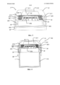
На фиг.3 показан подробный вид поперечного сечения колпака в первом варианте осуществления,Figure 3 shows a detailed cross-sectional view of the cap in the first embodiment,
На фиг.4 показано поперечное сечение контейнера в сборе в первом положении в первом варианте осуществления,Figure 4 shows a cross section of a container assembly in a first position in a first embodiment,
На фиг.5 показано поперечное сечение первого варианта осуществления контейнера в сборе в первом положении со слегка прижатой крышкой,Figure 5 shows a cross section of a first embodiment of a container assembly in a first position with a slightly pressed lid,
На фиг.6 показано поперечное сечение первого варианта осуществления контейнера в сборе во втором положении, где уплотнение было разрушено, иFIG. 6 shows a cross section of a first embodiment of a container assembly in a second position where the seal has been broken, and
На фиг.7 показан вид, соответствующий фиг.3, контейнера в сборе во втором варианте осуществления,7 shows a view corresponding to figure 3, the container Assembly in the second embodiment,
На фиг.8 показан перспективный вид контейнера в сборе в третьем варианте осуществления,On Fig shows a perspective view of the container Assembly in the third embodiment,
На фиг.9 показано поперечное сечение контейнера в сборе в первом положении в третьем варианте осуществления,FIG. 9 shows a cross-section of a container assembly in a first position in a third embodiment,
На фиг.10 показано поперечное сечение контейнера в сборе во втором положении в третьем варианте осуществления,Figure 10 shows a cross section of a container assembly in a second position in a third embodiment,
На фиг.11 показано поперечное сечение контейнера в сборе в третьем варианте осуществления,11 shows a cross section of a container assembly in a third embodiment,
На фиг.12 показан перспективный вид контейнера в сборе в четвертом варианте осуществления,On Fig shows a perspective view of the container Assembly in the fourth embodiment,
На фиг.13 показано поперечное сечение контейнера в сборе в первом положении в четвертом варианте осуществления.On Fig shows a cross section of the container Assembly in the first position in the fourth embodiment.
На фиг.14 показано поперечное сечение контейнера в сборе в первом положении в пятом варианте осуществления.On Fig shows a cross section of the container Assembly in the first position in the fifth embodiment.
На фиг.15 показано поперечное сечение контейнера в сборе во втором положении в пятом варианте осуществления.On Fig shows a cross section of the container Assembly in the second position in the fifth embodiment.
На фиг.16 показано поперечное сечение контейнера в сборе в первом положении в шестом варианте осуществления.On Fig shows a cross section of the container Assembly in the first position in the sixth embodiment.
На фиг.17 показано поперечное сечение контейнера в сборе во втором положении в шестом варианте осуществления.On Fig shows a cross section of the container Assembly in the second position in the sixth embodiment.
На фиг.18 показан вид в разобранном состоянии контейнера в сборе в шестом варианте осуществления, а также вид контейнера в сборе в собранном состоянии.On Fig shows an exploded view of the container Assembly in the sixth embodiment, as well as a view of the container Assembly in the assembled state.
На фиг.19 показан вид в разобранном состоянии контейнера в сборе в седьмом варианте осуществления, а также перспективный вид контейнера в сборе в собранном состоянии.FIG. 19 shows an exploded view of an assembled container in a seventh embodiment, as well as a perspective view of an assembled container.
На фиг.20 показан контейнер в сборе в собранном состоянии в седьмом варианте осуществления.20 shows an assembled container assembly in a seventh embodiment.
На фиг.21 показано поперечное сечение контейнера в сборе в первом положении в седьмом варианте осуществления.On Fig shows a cross section of the container Assembly in the first position in the seventh embodiment.
Одинаковые ссылочные номера относятся к одинаковым характерным признакам на чертежах.The same reference numbers refer to the same characteristic features in the drawings.
На фиг.1 показан контейнер в сборе в общем обозначенный номером 100 и содержащий контейнер 1 для хранения образца ткани, и колпак 2 в собранном состоянии. В изображенном варианте осуществления колпак 2 содержит кольцевой элемент 26, содержащий желобки для более прочного зажима, и верхний элемент 21. Вместо этого кольцевой элемент 26 может быть оснащен резиновой поверхностью или просто гладкой поверхностью. Верхний элемент 21 оснащен выступом (выступами) 214 для облегчения удерживания верхнего элемента 21, когда верхний элемент 21 необходимо повернуть. Колпак образует крышку, благодаря чему контейнер в сборе легко транспортировать. В изображенном варианте осуществления контейнер в сборе находится в собранном состоянии с максимальной толщиной, глубиной или длиной вдоль одной из сторон, равной 35 мм, что позволяет отправить его в письме. Максимальный размер одной из сторон контейнера также может составлять 20 мм, 25 мм или 50 мм. Размер одной из сторон контейнера в сборе может быть больше или даже меньше. Резервуар в данном варианте осуществления приспособлен для содержания 10 мл консерванта, такого как формалин. Резервуар может содержать различное количество консерванта, такое как менее 15 мл, менее 20 мл, менее 25 мл, менее 50 мл, менее 100 мл или менее 10 мл консерванта, или более 100 мл консерванта. Контейнер 1 по меньшей мере способен содержать соответствующее количество консерванта, а также образец ткани. Образец ткани может занимать до 1 см, но, скорее всего, будет иметь меньшую площадь, около 1 мм3. Образец ткани может быть покрыт консервантом вне зависимости от ориентации контейнера в сборе.Figure 1 shows the container assembly, generally indicated by the
На фиг.2 показаны различные части контейнера 100 в сборе в первом варианте осуществления. Помимо верхнего элемента 21, колпак содержит уплотнение 22 в форме фольги. Уплотнение также может представлять собой пленку, мембрану, полимер, композитный материал или стекло. Верхний элемент 21 выполнен из полимерного материала, но может быть выполнен из других материалов, таких как стекло. В изображенном варианте осуществления колпак 2 дополнительно содержит уплотнительную прокладку 24 в форме уплотнительного кольца для герметизации соединения между кольцевым элементом 26 и верхним элементом 21. Могут быть применены другие уплотнительные средства.FIG. 2 shows various parts of the
Между перфорирующим или прокалывающим элементом 23 и верхним элементом 21 находится упругий элемент 25, в форме размещенной пружины, для принудительного перемещения перфорирующего или прокалывающего элемента 23 от уплотнения 22. В других вариантах осуществления упругий элемент 25 может быть выполнен из другого упругого материала, такого как резина, или может иметь форму гибких стержней, расположенных вдоль длины окружности перфорирующего или прокалывающего элемента 23, или внутри верхнего элемента 21 вдоль длины окружности резервуара 211. Стержни могут быть выполнены из полимера или металла. Упругий элемент 25 может быть встроен в верхний элемент 21 или перфорирующий или прокалывающий элемент 23.Between the perforating or piercing
В данном варианте осуществления перфорирующий или прокалывающий элемент 23 в форме перфоратора или плунжера снабжен отверстиями 232 в области перфорирующего или прокалывающего элемента 23, приспособленной для введения в резервуар 211. Отверстия 232 способствуют жидкостному соединению между резервуаром и контейнером 1. Перфорирующий или прокалывающий элемент 23 дополнительно или в качестве альтернативы может быть оснащен отверстиями, расположенными вдоль фланца 233, не предназначенного для введения в резервуар 211. Перфорирующий или прокалывающий элемент 23 является полым, но также может быть цельным и оснащенным одним более крупным отверстием или несколькими меньшими отверстиями для способствования жидкостному соединению между резервуаром 211 и контейнером 1. Благодаря тому, что перфорирующий или прокалывающий элемент 23 выполнен цельным и его форма подогнана к форме резервуара 211, или благодаря лишь тому, что перфорирующий или прокалывающий элемент 23 оснащен отверстием (отверстиями) вдоль фланца 233, резервуар 211 либо полностью заполнен перфорирующим или прокалывающим элементом 23, либо соединение между резервуаром 21 и контейнером 1 герметично перекрывается по достижении перфорирующим или прокалывающим элементом 23 своего конечного положения. Это предотвращает отделение консерванта от образца ткани. Лишь минимальная часть либо нулевое количество консерванта может течь обратно в резервуар 211 и в пространство, недосягаемое для образца ткани, поскольку образец ткани может быть больше предоставленных отверстий.In this embodiment, the perforating or piercing
Наконец, контейнер 100 в сборе содержит контейнер 1, приспособленный для сцепления с кольцевым элементом 26. Сцепление между этими двумя деталями может осуществляться либо посредством резьбы, либо посредством давления на колпак, путем нажатия на упругий круговой фланец на кольцевом элементе 26 над фланцем или другие выступы на контейнере 1, или наоборот. Кольцевой элемент 26 в данном варианте осуществления применяется для удерживания контейнера 1 и верхнего элемента 21 вместе, и способствует регулировке глубины надавливания на верхний элемент 21.Finally, the assembled
Контейнер 1 и/или колпак 2 могут быть оснащены прозрачной частью для обеспечения обзора внутренней части контейнера 1 для визуального определения того, что образец ткани находится в контейнере 1, или что уплотнение 22 было разрушено и консервант находится в контейнере 1. Контейнер 1 и колпак 2 могут быть оснащены запирающим механизмом для предотвращения несанкционированного доступа к образцу ткани по пути из больницы в лабораторию. Запирающий механизм может представлять собой такой тип механизма, которой может быть открыт лишь персоналом лаборатории или он может представлять собой индикатор, указывающий на то, что контейнер 100 в сборе был открыт.The
На фиг.3 показано увеличенное изображение варианта осуществления колпака 2 в собранном состоянии.Figure 3 shows an enlarged image of a variant of implementation of the
Как подробно изображено на данной фигуре, верхний элемент 21 оснащен резервуаром 211, расположенным внутри верхнего элемента 21 в изображенном варианте осуществления. Верхний элемент 21 дополнительно оснащен средством сцепления в форме зубцов 213. Они приспособлены для сцепления с выступами 261, предоставленными на кольцевом элементе 26. Сцепление этих двух элементов фиксирует верхний элемент 21 в одном положении, а также предоставляет запас безопасности относительно глубины надавливания на верхний элемент 21. При отсутствии подобного ограничителя перемещения было бы возможно случайно нажать на верхний элемент 21 и разрушить уплотнение 22. Дополнительно, кольцевой элемент 26 оснащен выступом (выступами) 262, удерживающим (удерживающими) перфорирующий или прокалывающий элемент 23 в одном положении. В показанном варианте осуществления перфорирующий или прокалывающий элемент 23 оснащен резьбой 231, приспособленной для сцепления с резьбой 212 внутри верхнего элемента 21. Они предотвращают нажатие снизу на перфорирующий или прокалывающий элемент 23, приводящее к непреднамеренному разрушению уплотнения 22. Когда необходимо разрушить уплотнение 22, верхний элемент 21 перемещают вперед таким образом, чтобы разрушить уплотнение 22. В данном варианте осуществления верхний элемент 21 необходимо повернуть в то же время, когда на верхний элемент 21 нажимают сверху, одновременно с нажиманием снизу на перфорирующий или прокалывающий элемент 23. Контейнер 1 нажимает снизу на перфорирующий или прокалывающий элемент 23. Перед разрушением уплотнения 22 колпак 2 и контейнер 1 предпочтительно герметично соединяют.As shown in detail in this figure, the
В показанном варианте осуществления резервуар 211 имеет коническую форму, так что отверстие резервуара 516 шире дна 215. Резервуар может иметь другие формы, такие как цилиндрическую, многоугольную в виде пирамиды или другие формы. Соответственным образом, перфорирующий или прокалывающий элемент может иметь подобную форму.In the shown embodiment, the
Во всех вариантах осуществления резервуар в колпаке может быть заполнен консервантом непосредственно на месте изготовления колпака или, по меньшей мере, перед доставкой колпака пользователю. Резервуар может быть заполнен консервантом через отверстие, которое затем герметизируют уплотнением.In all embodiments, the implementation of the tank in the cap may be filled with preservative directly at the place of manufacture of the cap, or at least before delivery of the cap to the user. The reservoir may be filled with preservative through an opening, which is then sealed with a seal.
Из варианта осуществления по фиг.4 видно, что перфорирующий или прокалывающий элемент 23 опирается на кромку контейнера 1 и посредством установки колпака 2 на контейнер 1 перфорирующий или прокалывающий элемент 23 немного толкается вверх. Это обеспечивает то, что перфорирующий или прокалывающий элемент 23 может продвигаться вперед только тогда, когда колпак 2 установлен на контейнере 1. Если бы верхний элемент 23 повернули, то средства 231 и 212 сцепления по-прежнему не смогли бы войти в сцепление. В данном варианте осуществления верхний элемент 21 также необходимо нажать. Эта дополнительная мера безопасности, заключающаяся в том, что верхний элемент 21 также необходимо нажать для того, чтобы разрушить уплотнение 22, является необязательной.From the embodiment of FIG. 4, it can be seen that the perforating or piercing
Вместо продвижения сцепления средства сцепления на верхнем элементе 212 со средством сцепления на перфорирующем или прокалывающем элементе 231 путем поворота верхнего элемента 21, может происходить внезапное высвобождение консерванта, когда уплотнение 22 разрушено путем нажатия сверху вниз на верхний элемент 21 без поворота верхнего элемента 21. В данном случае зубец 213 проходит дальше вверх и не останавливает выступ 261 до тех пор, пока уплотнение 22 не будет разрушено.Instead of advancing the engagement of the engagement means on the
Между кольцевым элементом 26 и контейнером 1 может быть предоставлена дополнительная уплотнительная прокладка (не показана) для дополнительного уплотнения этих двух деталей.Between the
Прерывистая линия окружает объем 110, остающийся неизменным в ходе разрушения уплотнения 22. Объем 110 ограничен внутренней частью наружных стенок контейнера 100 в сборе. Внутренняя часть представляет собой внутреннюю стенку верхнего элемента 21, кольцевой элемент 23 и контейнер 1. Там где детали частично пересекаются, они представляют собой наибольшую внутреннюю часть, ограничивающую объем.A dashed line surrounds the
На фиг.5 на верхний элемент 21 нажали в направлении вниз, как видно на сцеплении между выступом 261 и зубцом 213. Перфорирующий или прокалывающий элемент 23 подготовлен для сцепления с верхним элементом 21. Путем поворота верхнего элемента на 180-360 градусов перфорирующий или прокалывающий элемент принудительно перемещают сквозь уплотнение и уплотнение разрушается. Уплотнение 22 разрушается снизу, что означает, что перфорирующий или прокалывающий элемент 23 находится снаружи резервуара 211 перед разрушением уплотнения 22. Верхний элемент можно повернуть более или менее для разрушения уплотнения 22 и для того, чтобы он достиг своего конечного положения.5, the
На фиг.6 показан перфорирующий или прокалывающий элемент 23 в конечном положении. Верхняя часть перфорирующего или прокалывающего элемента 23 над фланцем 233 точно вмещается в резервуар 211. Верхняя часть перфорирующего или прокалывающего элемента может быть больше или меньше резервуара 211. После разрушения уплотнения она размещается между верхним элементом 21 и перфорирующим или прокалывающим элементом 23, и предотвращается попадание уплотнения 22 в контейнер 1. Перфорирующий или прокалывающий элемент 23 служит опорой для уплотнения 22 после разрушения уплотнения 22. Уплотнение 22 также может представлять собой такой тип уплотнения, который при прокалывании растягивается к сторонам, оставляя лишь кольцо уплотнительного материала вдоль кромки отверстия резервуара 216. Пространство, оставшееся после того, как перфорирующий или прокалывающий элемент 23 достиг своего конечного положения, предпочтительно меньше 1/20 пространства в резервуаре от отверстия 216 до дна 215 или расстояние от дна 215 резервуара до перфорирующего или прокалывающего элемента 23 меньше 1 мм.Figure 6 shows the perforating or piercing
На фиг.1-6 показаны различные возможные положения или состояния контейнера в сборе.Figure 1-6 shows the various possible positions or conditions of the container assembly.
На фиг.1-3 предоставлен колпак, содержащий верхний элемент с резервуаром и перфорирующий или прокалывающий элемент. На фиг.3 резервуар заполнен консервантом и резервуар герметично закрыт. На фиг.4 образец ткани (не показан) помещен в возможно пустой контейнер, и колпак введен в сцепление с контейнером. На фиг.5 верхний элемент нажат вниз и на фиг.6 перфорирующий или прокалывающий элемент смещен путем сцепления средства сцепления перфорирующего или прокалывающего элемента со средством сцепления на верхнем элементе. Впоследствии происходит разрушение или прокалывание уплотнения, и консервант может поступать в контейнер.1-3, a cap is provided comprising an upper element with a reservoir and a perforating or piercing element. 3, the reservoir is filled with a preservative and the reservoir is hermetically closed. 4, a tissue sample (not shown) is placed in a possibly empty container, and the cap is engaged with the container. In Fig. 5, the upper element is pressed down, and in Fig. 6, the perforating or piercing element is biased by engaging the coupling means of the perforating or piercing element with the coupling means on the upper element. Subsequently, the seal is broken or punctured, and the preservative can enter the container.
На фиг.7 показан контейнер в сборе во втором варианте осуществления. Второй вариант осуществления работает так же, как описано для первого варианта осуществления, и признаки с одинаковым ссылочным номером являются одинаковыми. В данном случае разница заключается в том, что контейнер 10 выступает вверх в перфорирующий или прокалывающий элемент 23. Таким образом, перфорирующий или прокалывающий элемент 23 имеет возможность опираться на выступ 262 на контейнере или на кромке контейнера. Таким образом, выступ 262 или кромка контейнера толкает перфорирующий или прокалывающий элемент 23 вверх. Благодаря тому, что контейнер выступает в перфорирующий или прокалывающий элемент, персонал открывающий контейнер в сборе, лучше защищен от утечки, поскольку стенка над уровнем консерванта в контейнере имеет большую высоту.7 shows a container assembly in a second embodiment. The second embodiment works the same way as described for the first embodiment, and the features with the same reference number are the same. In this case, the difference lies in the fact that the
На фиг.8-11 показан третий вариант осуществления изобретения. Как показано на фиг.8, контейнер в сборе содержит контейнер 1 и колпак 2, при этом колпак 2 содержит защитный наконечник 27 и верхний элемент 21. Цель защитного наконечника 27 заключается в предотвращении непреднамеренного нажатия на мембрану (см. фиг.9 и 10). Защитный наконечник 27 может быть поворачиваемым или съемным. Верхний элемент 21 оснащен выступами 29 для легкого захвата и его отсоединяют от контейнера 1 посредством поворота. Диаметр 0 данного варианта осуществления составляет 33 мм, но может быть меньше или больше. Высота H составляет 47 мм, но может быть меньше или больше. Резервуар 211 может быть выше, так что он может содержать больше консерванта. Резервуар 211 и контейнер 1 предпочтительно должны иметь возможность содержать около 20 мл консерванта, соответственно.8-11 show a third embodiment of the invention. As shown in FIG. 8, the container assembly comprises a
На фиг.9 контейнер в сборе находится в первом положении и на фиг.10 он находится во втором положении. Поперечное сечение на фиг.9-10 выполнено вдоль линии А-А, как показано на фиг.8, и на фиг.11 показано поперечное сечение вдоль линии В-В, также показанной на фиг.8. Контейнер 1 приспособлен для размещения образца 45 ткани, и колпак содержит верхний элемент 321. Разделитель 31 расположен между уплотнением 22 и дном 13 контейнера. Таким образом, в установленном состоянии, когда колпак прикреплен к контейнеру 1, контейнер 1 разделен на два пространства, первое пространство 11 и второе пространство 12. Несмотря на то, что пространства 11, 12 разделены, это не обязательно означает, что разделитель 31 и контейнер 1 являются влагонепроницаемыми. Можно предотвратить перемещение жидкости в обход разделителя 31. Жидкость также может перемещаться в обход разделителя 31 вместо перемещения сквозь разделитель 31. Внутренняя окружность контейнера 1 имеет по существу такой же размер, что и наружная окружность разделителя 31, но внутренняя окружность контейнера 1 может быть чуть больше наружной окружности разделителя 31.In Fig. 9, the container assembly is in a first position and in Fig. 10 it is in a second position. The cross section in FIGS. 9-10 is made along line AA, as shown in FIG. 8, and FIG. 11 shows a cross section along line BB, also shown in FIG. The
Как показано на фиг.9-10, верхний элемент 321 оснащен средством 324 сцепления, таким как резьба, для сцепления с контейнером 1. Контейнер 1 подобным образом оснащен средством 325 сцепления, в данном случае имеющим форму резьбы, для сцепления с соответствующей резьбой на верхнем элементе 321. В качестве альтернативы, сцепление между верхним элементом 321 и контейнером 1 может быть осуществлено посредством защелок. Кроме этого, верхний элемент 321 оснащен средством 326 сцепления для сцепления с прокалывающим элементом 323. Средство 326 сцепления имеет форму четырех щелей в полой цилиндрической форме, приспособленной для приема прокалывающего элемента 323. Цилиндрическая форма может быть цельной и/или количество щелей может изменяться. Вместо этого средство сцепления может иметь форму защелки. Кроме того, верхний элемент 321 может быть оснащен средством 327 сцепления для сцепления со средством 328 сцепления, предоставленным на внутренней стороне разделителя 31. Таким образом, разделитель 31 остается присоединенным к колпаку 2 после удаления колпака 2 из контейнера 1, например, для извлечения образца ткани. Средства 327, 328 сцепления могут иметь форму резьбы или защелки.As shown in FIGS. 9-10, the
Мембрана 28 расположена поверх верхнего элемента 321. На фиг.9 она имеет по существу выпуклую форму, а на фиг.10 она имеет по существу вогнутую форму. Когда давление прекращает воздействовать на мембрану 28, мембрана 28 будет сохранять свою вогнутую форму. Это позволяет персоналу визуально определить сверху высвобождение консерванта. Поскольку контейнер 1 предпочтительно является прозрачным, сквозь контейнер 1 можно увидеть, был ли высвобожден консервант. Мембрана 28 может быть упругой мембраной, автоматически возвращающейся в свое первое положение. Прокалывающий элемент 323 активируют нажатием на мембрану 28. Таким образом, прокалывающий элемент 323 смещают вдоль продольной оси контейнера в сборе и разрывают или разрушают уплотнение 22, отделяющее резервуар 211 от контейнера 1.The
В показанном варианте осуществления прокалывающий элемент 323 оснащен зубьями 329 для прокалывания уплотнения 22. Прокалывающий элемент 323 выполнен из полимерного материала, но также может быть выполнен из металла или других подходящих материалов. Предоставлен дополнительный пробивающий элемент 330 для пробивания уплотнения 22, но он является необязательным.In the shown embodiment, the piercing
Уплотнение 22 может представлять собой фольгу, пленку или полимерную мембрану.The
Разделитель 31 приспособлен для того, чтобы удерживаться на колпаке 2. На дне 13 разделителя 31 предоставлена сетка. Разделитель 31 должен обладать способностью пропускать сквозь себя консервант и одновременно обеспечивать, чтобы уплотнение 22 не попадало в контейнер 1 и обеспечивать, чтобы образец 45 ткани не перемещался в резервуар 211 при транспортировке.The
Ссылаясь на фиг.11, отверстия 291 в сетке в разделителе 31 являются квадратными, размер каждого отверстия в поперечном направлении равен прибл. 1 мм, они могут быть больше или меньше, круглой или многоугольной формы. Сетка является проницаемой для жидкости с поверхностным натяжением подобным поверхностному натяжению воды. Также может быть применен другой тип проницаемой мембраны. Разделитель 31 может быть оснащен отверстиями, расположенными в другом месте, например, в стенках разделителя 31. Разделитель 31 не является контейнером для образца ткани, таким как кассета, но вместо этого разделяет контейнер 1 на два пространства, соединенных между собой. Второе пространство 12 и/или дно контейнера 1 приспособлено для размещения образца 45 ткани. Первое пространство 11 также может быть расположено в колпаке 2. Как показано на фиг.9-11, разделитель 31 дополнительно оснащен каналом 30 с отверстием или воздуховыпускным отверстием в дне разделителя 31 и отверстием или воздуховыпускным отверстием, расположенным на расстоянии от воздуховыпускного отверстия. Воздуховыпускное отверстие расположено таким образом, что когда уплотнение 22 разрушено и консервант покинул резервуар 211, консервант не может пройти сквозь сетку из-за малого размера отверстий и поверхностного натяжения консерванта, и для его прохождения необходимо, например, встряхнуть контейнер в сборе. Проницаемость сетки может быть увеличена с помощью канала 30, позволяющего воздуху в контейнере 1 перемещаться в обход консерванта по каналу 30 и тем самым позволяя консерванту проходить сквозь отверстия 291 в сетке. Следовательно, отверстие или воздуховыпускное отверстие расположено таким образом, чтобы находиться выше уровня консерванта после разрушения уплотнения 22. В данном варианте осуществления предоставлено два канала 30, но вместо этого может быть предоставлен один или более двух каналов 30 и другие формы каналов. Разделитель 31 или, по меньшей мере, сетка имеет синий или другой цвет, контрастирующий с цветом образца ткани. Это позволяет легче увидеть образец ткани в том случае, если он прилип к разделителю 31. Разделитель может иметь другой цвет. Пространство 12 для образца 45 ткани находится под разделителем 31. Контейнер в сборе может быть оснащен отслеживающим устройством, таким как метка RFID (радиочастотной идентификации), так что путь образца можно отслеживать от его получения до теста в лаборатории. Образец 45 не обязательно должен быть постоянно покрыт консервантом, поскольку паров в контейнере 1 обычно будет достаточно для сохранения образца 45.Referring to FIG. 11, the
На фиг.12 и 13 показан четвертый вариант осуществления изобретения в форме контейнера 400 в сборе. На фиг.13 показано поперечное сечение контейнера в сборе вдоль линии А-А, как показано на фиг.12. Все признаки и функции, присутствующие в третьем варианте осуществления, подобным образом присутствуют в четвертом варианте осуществления, где одинаковые ссылочные номера обозначают одинаковые признаки. Разница между третьим и четвертым вариантом осуществления заключается в том, что четвертый вариант осуществления имеет большую высоту и способен содержать около 20 мл формалина или другого консерванта как в резервуаре 211, так и в контейнере 1. Канал (каналы) 30 в данном варианте осуществления не удлинен, поскольку требуется некоторое время перед тем, как консервант пройдет через разделитель 31 и таким образом канал (каналы) 30 все еще будет находиться над уровнем консерванта после разрушения уплотнения 22. Канал (каналы) 30 может быть удлинен, например на 2-5 см. Может быть предусмотрен любой размер контейнера, способный содержать около 5-50 мл консерванта.12 and 13 show a fourth embodiment of the invention in the form of an assembled
На фиг.14 и 15 показан пятый вариант осуществления изобретения в форме контейнера 500 в сборе. Все признаки и функции, присутствующие в третьем и четвертом вариантах осуществления, подобным образом присутствуют в пятом варианте осуществления, где одинаковые ссылочные номера обозначают одинаковые признаки. На фиг.14 контейнер 500 в сборе находится в первом положении и на фиг.15 он находится во втором положении. Помимо функций, подобных ранее описанным в третьем и/или четвертом вариантах осуществления, контейнер 500 в сборе дополнительно содержит съемный наконечник 528, оснащенный средствами 548 удержания. Наконечник 528 защищает мембрану 28 от давления при транспортировке.FIGS. 14 and 15 show a fifth embodiment of the invention in the form of an assembled
На фиг.16-18 показан шестой вариант осуществления изобретения в форме контейнера 600 в сборе. Контейнер 600 в сборе отличается, помимо прочего от третьего варианта осуществления тем, что верхний элемент 621 имеет большую высоту и может содержать больше консерванта. Перфорирующий или прокалывающий элемент 323 также имеет большую высоту и оснащен крестообразным или Т-образным выступом 626, расположенным сверху. Выступ 626 опирается на круговой фланец 627, расположенный на верхнем элементе 621. Таким образом, при нажатии на мембрану 28 сверху вниз, выступ вынужденно перемещается через круговой фланец 627, на который он опирался в своем исходном положении. Круговой фланец 627 или выступ 626 может обладать упругими свойствами, позволяющими выступу 626 проходить через круговой фланец 627. Выступ 626 может иметь коническую форму с тем, чтобы он легче проходил через фланец 627 при нажиме. Круговой фланец 627 также может иметь форму круговых выступов, не соединенных вдоль всей длины окружности. Верхний элемент 621 может быть присоединен к контейнеру 1, так что наружная часть верхнего элемента 621 входит в сцепление с внутренней частью контейнера 1. Это может также быть наоборот. Верхний элемент 621 и контейнер 1 могут быть оснащены средством сцепления в форме резьбы.16-18, a sixth embodiment of the invention is shown in the form of an assembled
Кроме этого, разделитель 31 оснащен каналом (каналами) 31 в форме сегментов. Благодаря тому, что стенка канала (каналов) проходит через разделитель 31 в виде хорды, разделитель 31 приобретает большую жесткость. Канал (каналы) 30 не проходит (проходят) над верхней кромкой разделителя 31, но может проходить таким образом в других вариантах осуществления.In addition, the
Верхний элемент 621 проходит над наивысшей точкой мембраны 28 в первом положении, тем самым защищая мембрану 28 от давления при отсутствии защитного наконечника. Наивысшей точкой в данном варианте осуществления является центр мембраны.The
Шестой вариант осуществления может дополнительно включать любой признак из третьего, четвертого и пятого варианта осуществления.The sixth embodiment may further include any feature of the third, fourth, and fifth embodiment.
На фиг.19-21 показан седьмой вариант осуществления изобретения. Помимо признаков шестого варианта осуществления контейнер 700 в сборе дополнительно оснащен наконечником 728. Верхний элемент 721 не проходит за пределы наивысшей точки мембраны 28, в отличие от шестого варианта осуществления. Седьмой вариант осуществления может содержать любые признаки из третьего, четвертого, пятого и шестого варианта осуществления.19-21 show a seventh embodiment of the invention. In addition to the features of the sixth embodiment, the
Под термином «разрушенное» подразумевается, что в пленке или уплотнении образовано отверстие, через которое может вытекать консервант, либо через которое извне могут попадать частицы или загрязняющие вещества.By the term “broken” is meant that a hole is formed in the film or seal through which a preservative can flow out, or through which particles or contaminants can enter from the outside.
Термин «колпак», как применяется в настоящем описании, включает в себя все средства, закрывающие отверстие контейнера. Термин «разделитель» применяется для обозначения элемента, применяемого для отделения уплотнения от потенциального образца ткани, помещенного в контейнер. В некоторых вариантах осуществления разделитель также выполняет функцию перфорирующего или прокалывающего элемента, так что разделитель и прокалывающий элемент образуют один элемент, в то время, как в других вариантах осуществления прокалывающий элемент и разделитель являются отдельными элементами.The term "cap", as used herein, includes all means covering the opening of the container. The term “separator” is used to refer to an element used to separate a seal from a potential tissue sample placed in a container. In some embodiments, the separator also functions as a perforating or piercing element, such that the separator and the piercing element form one element, while in other embodiments, the piercing element and the separator are separate elements.
Термин «контейнер» обычно применяют для обозначения контейнера или пространства, приспособленного для содержания образца ткани.The term “container” is usually used to mean a container or space adapted to contain a tissue sample.
Кроме того, предусмотрено применение других конфигураций контейнера в сборе. Он может иметь промышленный размер, где контейнер способен содержать по меньшей мере 1 л или менее 5 л, 10 л, 100 л, 1000 л или более. Контейнер может содержать вещество, которое необходимо смешать со вторым веществом меньшего объема. Колпак или крышка могут иметь возможность содержать второе вещество с объемом менее 5 мл, 10 мл, 30 мл, 50 мл, 100 мл или более 100 мл, которое необходимо смешать с веществом в контейнере. Второе вещество может быть токсичным или летучим веществом или веществом, которое необходимо ввести в контейнер в точном количестве. Этот более крупный контейнер в сборе может обладать теми же признаками, что и первый, второй, третий или четвертый вариант осуществления. Любой признак этих вариантов осуществления может быть применен независимо от других признаков к данному более крупному контейнеру в сборе.In addition, other assembly configurations are contemplated. It may be of industrial size, where the container is capable of containing at least 1 liter or less than 5 liters, 10 liters, 100 liters, 1000 liters or more. The container may contain a substance that must be mixed with a second substance of a smaller volume. The cap or cap may be able to contain a second substance with a volume of less than 5 ml, 10 ml, 30 ml, 50 ml, 100 ml or more than 100 ml, which must be mixed with the substance in the container. The second substance may be a toxic or volatile substance or a substance that must be introduced into the container in an exact amount. This larger container assembly may have the same features as the first, second, third or fourth embodiment. Any feature of these embodiments may be applied, independently of other features, to a given larger container assembly.
В общем, признаки показанных и описанных вариантов осуществления можно свободно комбинировать и ни один признак не должен расцениваться как обязательный, если в независимых пунктах формулы изобретения не указано иначе.In general, the features of the shown and described embodiments can be freely combined and no feature should be regarded as mandatory unless otherwise indicated in the independent claims.
Claims (19)
- контейнер (1) для размещения образца (45) биологической ткани; при этом указанный контейнер (1) содержит дно (13);
- колпак (2), приспособленный для сцепления с указанным контейнером (1), при этом указанный колпак (2) содержит:
- верхний элемент (21), содержащий резервуар (211), при этом указанный резервуар (211) приспособлен для того, чтобы содержать консервант,
- уплотнение (22) для герметичного закрывания указанного резервуара (211);
- прокалывающий элемент (323) для разрушения указанного уплотнения (22) путем смещения указанного прокалывающего элемента (323);
причем контейнер (300) в сборе имеет первое и второе положение, и в первом положении контейнер (1) изолирован от резервуара (211), а во втором положении между резервуаром (211) и контейнером (1) обеспечено жидкостное соединение, отличающийся тем, что контейнер (300) в сборе содержит разделитель (31), расположенный между уплотнением и дном (13) контейнера (1), и разделитель (31) имеет по меньшей мере одно отверстие (291), приспособленное для обеспечения прохождения текучей среды между резервуаром (211) и контейнером (1).1. The container (300) Assembly for storing a sample (45) of biological tissue, containing:
- a container (1) for placing a sample (45) of biological tissue; wherein said container (1) contains a bottom (13);
- a cap (2) adapted for coupling with said container (1), wherein said cap (2) contains:
- the upper element (21) containing the reservoir (211), while the specified reservoir (211) is adapted to contain a preservative,
- a seal (22) for tightly closing said reservoir (211);
a piercing element (323) for breaking said seal (22) by displacing said piercing element (323);
moreover, the container (300) assembly has a first and second position, and in the first position, the container (1) is isolated from the tank (211), and in the second position between the tank (211) and the container (1) a fluid connection is provided, characterized in that the container (300) in the assembly contains a separator (31) located between the seal and the bottom (13) of the container (1), and the separator (31) has at least one opening (291), adapted to allow the passage of fluid between the tank (211 ) and the container (1).
- предоставления контейнера (1),
- предоставления колпака (2), содержащего верхний элемент (21) с резервуаром (211), заполненным консервантом и герметично закрытым уплотнением (22), прокалывающий элемент (323) и разделитель (31),
- размещения образца биологической ткани в указанном контейнере (1),
- ввода указанного колпака (2) в сцепление с контейнером (1), тем самым размещая указанный разделитель (31) между уплотнением (22) и дном (13) контейнера (1),
- смещения прокалывающего элемента (323), тем самым разрушая указанное уплотнение (22), что позволяет консерванту поступать в контейнер (1) через разделитель (31). 19. A method of storing a sample (45) of biological tissue, comprising the steps of:
- providing a container (1),
- providing a cap (2) containing an upper element (21) with a reservoir (211) filled with a preservative and hermetically sealed seal (22), a piercing element (323) and a separator (31),
- placing a sample of biological tissue in the specified container (1),
- entering the specified cap (2) into engagement with the container (1), thereby placing the specified separator (31) between the seal (22) and the bottom (13) of the container (1),
- displacement of the piercing element (323), thereby destroying the specified seal (22), which allows the preservative to enter the container (1) through the separator (31).
Applications Claiming Priority (3)
| Application Number | Priority Date | Filing Date | Title |
|---|---|---|---|
| DKPA201170297 | 2011-06-14 | ||
| DKPA201170297 | 2011-06-14 | ||
| PCT/DK2011/050434 WO2012171529A1 (en) | 2011-06-14 | 2011-11-11 | Container assembly and associated method |
Publications (2)
| Publication Number | Publication Date |
|---|---|
| RU2013156531A RU2013156531A (en) | 2015-07-20 |
| RU2604125C2 true RU2604125C2 (en) | 2016-12-10 |
Family
ID=44993432
Family Applications (1)
| Application Number | Title | Priority Date | Filing Date |
|---|---|---|---|
| RU2013156531/15A RU2604125C2 (en) | 2011-06-14 | 2011-11-11 | Container in assembly and associated method |
Country Status (24)
| Country | Link |
|---|---|
| US (2) | US9726585B2 (en) |
| EP (3) | EP3653132B1 (en) |
| JP (1) | JP5936088B2 (en) |
| CN (1) | CN103635147B (en) |
| AR (1) | AR086918A1 (en) |
| AU (1) | AU2011370782B2 (en) |
| BR (1) | BR112013031779B1 (en) |
| CA (1) | CA2837607C (en) |
| CL (1) | CL2013003388A1 (en) |
| CO (1) | CO6930343A2 (en) |
| DK (2) | DK2720617T4 (en) |
| ES (2) | ES2583057T5 (en) |
| HR (1) | HRP20160862T4 (en) |
| HU (1) | HUE029752T2 (en) |
| LT (1) | LT2720617T (en) |
| MX (1) | MX339841B (en) |
| NZ (1) | NZ618155A (en) |
| PE (1) | PE20141796A1 (en) |
| PL (1) | PL2720617T5 (en) |
| PT (1) | PT2720617T (en) |
| RS (1) | RS54918B2 (en) |
| RU (1) | RU2604125C2 (en) |
| SI (1) | SI2720617T1 (en) |
| WO (1) | WO2012171529A1 (en) |
Cited By (2)
| Publication number | Priority date | Publication date | Assignee | Title |
|---|---|---|---|---|
| RU173706U1 (en) * | 2016-12-19 | 2017-09-06 | Федеральное государственное автономное образовательное учреждение высшего образования "Национальный исследовательский технологический университет "МИСиС" | Device for storing and transporting dry blood |
| RU177743U1 (en) * | 2017-06-16 | 2018-03-07 | Федеральное государственное бюджетное образовательное учреждение высшего образования "Самарский государственный медицинский университет" Министерства здравоохранения Российской Федерации | BIOMATERIAL STORAGE CONTAINER |
Families Citing this family (42)
| Publication number | Priority date | Publication date | Assignee | Title |
|---|---|---|---|---|
| US9272827B2 (en) | 2008-08-29 | 2016-03-01 | Pepsico, Inc. | Post-mix beverage system |
| US9914126B2 (en) * | 2011-11-28 | 2018-03-13 | Roche Diabetes Care, Inc. | Storage container for biosensor test elements |
| CH708149A2 (en) * | 2013-06-10 | 2014-12-15 | Unicap Systems Ag | Drinking cap with foil sealed chamber and foil piercer. |
| CN103994909A (en) * | 2014-06-09 | 2014-08-20 | 上海微银生物技术有限公司 | Phlegm tank |
| EP3169599A4 (en) * | 2014-07-15 | 2017-06-28 | Vinnovate Pty Ltd. | Container cap |
| CN107106146B (en) * | 2014-11-17 | 2019-11-08 | 踪迹责任有限公司 | For collecting and saving the container of biopsy sample |
| CA2972315C (en) | 2015-01-26 | 2021-09-14 | Ventana Medical Systems, Inc. | Transporter systems, assemblies and associated methods for transporting tissue samples |
| CN113941381A (en) | 2015-02-20 | 2022-01-18 | 文塔纳医疗系统公司 | Assembly for storing and transporting tissue samples immersed in a fluid |
| ITUB20152656A1 (en) * | 2015-07-30 | 2015-10-30 | Tecnobilife S R L | Disposable container of 30 or 90 ml for the storage and transport of a sample of tissue or human organs to be subjected to histological examination. |
| WO2017070149A1 (en) * | 2015-10-23 | 2017-04-27 | The Hillman Group, Inc. | Wall anchors and related wall mount systems |
| ITUB20155037A1 (en) * | 2015-11-06 | 2017-05-06 | Traces S R L | Container for the collection and storage of biopsy samples. |
| US10464797B2 (en) | 2016-01-15 | 2019-11-05 | Pepsico, Inc. | Post-mix beverage system |
| ITUB20161093A1 (en) * | 2016-02-26 | 2017-08-26 | Co Me Plast Di Costalunga Francesco Davide & Figli S N C | CONTAINER FOR ORGANIC FABRIC SAMPLES |
| ITUA20161845A1 (en) * | 2016-03-21 | 2017-09-21 | Kaltek S R L | CONTAINMENT DEVICE FOR BIOLOGICAL SAMPLES |
| CA3023316A1 (en) * | 2016-05-05 | 2017-11-09 | Meccanica G.M. S.R.L. | Container assembly |
| US10610045B2 (en) | 2016-06-14 | 2020-04-07 | Pepsico, Inc. | Beverage system including a removable piercer |
| KR101798330B1 (en) * | 2016-06-22 | 2017-12-12 | 이현구 | Container for clinical specimen |
| KR101736745B1 (en) * | 2016-11-16 | 2017-05-29 | 김종민 | Specimen container for preserving tissue |
| IT201600120864A1 (en) * | 2016-11-29 | 2017-03-01 | Tecnobilife S R L | DISPOSABLE CONTAINER FOR HISTOLOGICAL EXAMINATION. |
| USD855707S1 (en) * | 2016-12-19 | 2019-08-06 | Jakobi International Limited | Connector |
| KR101973555B1 (en) * | 2017-03-06 | 2019-04-29 | 김종민 | Filtering member for specimen container |
| IT201700033118U1 (en) * | 2017-03-27 | 2018-09-27 | Vigeo S R L | SYSTEM FOR COLLECTING BIOPTIC SAMPLES |
| IT201700051294A1 (en) * | 2017-05-11 | 2018-11-11 | Diapath S P A | DEVICE AND METHOD FOR THE COLLECTION, CONSERVATION AND / OR TRANSPORT OF BIOLOGICAL SAMPLES |
| KR101997187B1 (en) * | 2017-05-15 | 2019-10-17 | (주)코아바이오텍 | A composition for identifying of mycobacterium and specimen container |
| KR101997193B1 (en) * | 2017-06-13 | 2019-07-05 | (주)코아바이오텍 | A method for smear treatment of specimen |
| CN108871908B (en) * | 2018-09-06 | 2024-06-25 | 杭州优思达生物技术股份有限公司 | Biological sample processing device |
| US20220117588A1 (en) * | 2019-01-10 | 2022-04-21 | Confirm Biosciences, Inc. | Device & method for saliva-based analyte testing |
| KR200490214Y1 (en) * | 2019-04-19 | 2019-10-11 | 진영석 | Filtering member for cytology diagnose including blade unit, and specimen container including the same |
| KR200490236Y1 (en) * | 2019-04-23 | 2019-10-16 | 김종민 | Filtering member for cytology diagnose including protrusions, and specimen container including the same |
| KR200490237Y1 (en) * | 2019-04-25 | 2019-10-16 | 김종민 | Specimen container for cytology diagnose having support part supporting filtering member |
| IT201900009999A1 (en) | 2019-06-25 | 2020-12-25 | Inge Spa | Bottle capping device suitable for storing a substance packaged in a pod and contained in a cavity of it. |
| KR102349346B1 (en) * | 2019-06-26 | 2022-01-11 | 박창규 | Biopsy container |
| AU2020398076A1 (en) * | 2019-12-02 | 2022-07-07 | Enrico BICOCCHI | Container for biologic samples and method for their preservation |
| EP4171388A1 (en) | 2020-06-24 | 2023-05-03 | CANOS Societa' a Responsabilita' Limitata Semplificata | Biopsy container assembly |
| CA3130654A1 (en) | 2020-09-15 | 2022-03-15 | Norgen Biotek Corp. | Sample collection apparatus and uses thereof |
| EP4231922A1 (en) * | 2020-10-22 | 2023-08-30 | Merit Medical Systems, Inc. | Saliva collection and transport devices, systems and methods |
| USD1009646S1 (en) * | 2021-08-06 | 2024-01-02 | Chubby Gorilla, Inc. | Container |
| WO2023033412A1 (en) * | 2021-08-30 | 2023-03-09 | (주)바이온라이프사이언스 | Kit for specimen storage |
| WO2023043069A1 (en) * | 2021-09-14 | 2023-03-23 | (주)바이온라이프사이언스 | Kit for specimen storage |
| WO2023183415A1 (en) * | 2022-03-24 | 2023-09-28 | ThoraGenix Innovations, Inc. | Tools for fusing two sections of bones and performing other medical procedures |
| JP7289577B1 (en) | 2022-12-13 | 2023-06-12 | 三晶エムイーシー株式会社 | sample container |
| CN117694936B (en) * | 2024-02-06 | 2024-05-24 | 新光维医疗科技(苏州)股份有限公司 | Sampling container, sampling connecting seat and endoscope |
Citations (1)
| Publication number | Priority date | Publication date | Assignee | Title |
|---|---|---|---|---|
| WO2008040812A1 (en) * | 2006-10-06 | 2008-04-10 | Sonion Roskilde A/S | Tissue handling system with reduced operator exposure |
Family Cites Families (37)
| Publication number | Priority date | Publication date | Assignee | Title |
|---|---|---|---|---|
| US3521745A (en) * | 1968-07-31 | 1970-07-28 | Gilbert Schwartzman | Mixing package |
| JPS581027B2 (en) * | 1977-05-31 | 1983-01-08 | ゲオルク・ヴイ−グネル | container |
| US4353868A (en) * | 1981-05-29 | 1982-10-12 | Sherwood Medical Industries Inc. | Specimen collecting device |
| DE8502008U1 (en) * | 1985-01-26 | 1985-08-29 | Celamerck Gmbh & Co Kg, 6507 Ingelheim | Closure cap for two-component packs |
| IT1185850B (en) * | 1985-08-02 | 1987-11-18 | Zambon Spa | DROP TANK CAP FOR BOTTLES |
| US4889992A (en) * | 1987-11-12 | 1989-12-26 | Max Hoberman | Automatic infrared microorganism detection instrument |
| US5152965A (en) | 1989-06-02 | 1992-10-06 | Abbott Laboratories | Two-piece reagent container assembly |
| US5145646A (en) * | 1991-06-03 | 1992-09-08 | Abbott Laboratories | Reagent bottle and cap |
| US5297696A (en) * | 1992-04-27 | 1994-03-29 | International Paper Company | Pour spout with piercing insert |
| US5255812A (en) * | 1992-07-01 | 1993-10-26 | Hsu Yu T | Container cap |
| JP3295014B2 (en) | 1997-03-19 | 2002-06-24 | 株式会社大日本精機 | Automatic extraction device for component substances in liquid samples and automatic concentration measurement device for component substances in liquid samples |
| US6043097A (en) | 1997-12-05 | 2000-03-28 | Bayer Corporation | Reagent package |
| US7147826B2 (en) | 2001-10-12 | 2006-12-12 | Becton Dickinson And Company | Method and apparatus for transporting biological samples |
| KR20030093938A (en) | 2002-06-04 | 2003-12-11 | 조영국 | bottle cap assembly for simultaneously dissolve additives |
| MXPA04011129A (en) | 2002-05-13 | 2005-02-17 | Becton Dickinson Co | Protease inhibitor sample collection system. |
| AU2003245635A1 (en) | 2002-06-25 | 2004-01-06 | Creare Incorporated | Mixing vial |
| JP4472634B2 (en) | 2003-07-10 | 2010-06-02 | ユニヴェルシテ リブル ドゥ ブリュッセル | Apparatus, kit and method for pulsing a biological sample with a reagent and thus stabilizing the pulsed sample |
| US7378054B2 (en) * | 2004-04-16 | 2008-05-27 | Savvipharm Inc | Specimen collecting, processing and analytical assembly |
| KR20050103807A (en) | 2004-04-27 | 2005-11-01 | (주)일렉콤 | Double cap for adding addition in use |
| TW200621992A (en) | 2004-06-23 | 2006-07-01 | Rosemary Katherine Cameron Sharpin | Improvements in and relating to micro-organism test apparatus and methods of using the same |
| JP4689998B2 (en) | 2004-09-24 | 2011-06-01 | キタノ製作株式会社 | Two-component mixing container |
| KR20060082504A (en) | 2005-01-12 | 2006-07-19 | 조영국 | Cap |
| ATE531311T1 (en) | 2005-12-09 | 2011-11-15 | Dna Genotek Inc | CONTAINER SYSTEM FOR STORING AND EASILY DISPENSING A SUBSTANCE |
| US20070215496A1 (en) | 2006-03-17 | 2007-09-20 | Scarborough Ella B | Bottle assembly |
| US20070270714A1 (en) | 2006-05-19 | 2007-11-22 | E-Z-Em, Inc. | System and method for tissue specimen collection |
| US7663101B2 (en) | 2006-05-22 | 2010-02-16 | Microscopy Innovations | System and methods for preparing microscopy samples |
| US8387811B2 (en) | 2007-04-16 | 2013-03-05 | Bd Diagnostics | Pierceable cap having piercing extensions |
| CN101848767B (en) | 2007-10-23 | 2015-02-18 | 贝克顿·迪金森公司 | Fluid displacement tissue container for molecular and histology diagnostics |
| ES2805503T3 (en) * | 2007-10-23 | 2021-02-12 | Becton Dickinson Co | Tissue container for molecular and histological diagnosis incorporating a breakable membrane |
| HK1117990A2 (en) | 2007-10-25 | 2009-01-23 | Sunrider Corp | Safety sealed reservoir cap |
| CN101896276A (en) | 2007-11-28 | 2010-11-24 | 智能管公司 | Devices, systems and methods for the collection, stimulation, stabilization, and analysis of a biological sample |
| CA2734736C (en) | 2008-08-21 | 2017-02-28 | Dna Genotek Inc. | Sample receiving device |
| WO2010028172A1 (en) * | 2008-09-03 | 2010-03-11 | Flava' Cap Llc | Universal closure apparatus with delivery system |
| US20100101340A1 (en) * | 2008-10-24 | 2010-04-29 | Dna Ident Inc. | Sample collecting device |
| US8684231B2 (en) | 2009-10-15 | 2014-04-01 | Thermos L.L.C. | Drink additive delivery lid system |
| US8443970B2 (en) | 2010-01-19 | 2013-05-21 | Karma Culture, Llc | Dispensing capsule |
| JP5572842B2 (en) | 2010-11-30 | 2014-08-20 | 独立行政法人日本原子力研究開発機構 | Precipitation strengthened Ni-base heat-resistant alloy and method for producing the same |
-
2011
- 2011-11-11 PE PE2013002806A patent/PE20141796A1/en active IP Right Grant
- 2011-11-11 RU RU2013156531/15A patent/RU2604125C2/en active
- 2011-11-11 CN CN201180071604.XA patent/CN103635147B/en active Active
- 2011-11-11 ES ES11784584T patent/ES2583057T5/en active Active
- 2011-11-11 EP EP19192316.8A patent/EP3653132B1/en active Active
- 2011-11-11 BR BR112013031779-5A patent/BR112013031779B1/en active IP Right Grant
- 2011-11-11 CA CA2837607A patent/CA2837607C/en active Active
- 2011-11-11 MX MX2013014716A patent/MX339841B/en active IP Right Grant
- 2011-11-11 AU AU2011370782A patent/AU2011370782B2/en active Active
- 2011-11-11 NZ NZ618155A patent/NZ618155A/en unknown
- 2011-11-11 EP EP16159677.0A patent/EP3061401B1/en active Active
- 2011-11-11 DK DK11784584.2T patent/DK2720617T4/en active
- 2011-11-11 JP JP2014515065A patent/JP5936088B2/en active Active
- 2011-11-11 PT PT117845842T patent/PT2720617T/en unknown
- 2011-11-11 LT LTEP11784584.2T patent/LT2720617T/en unknown
- 2011-11-11 PL PL11784584T patent/PL2720617T5/en unknown
- 2011-11-11 ES ES16159677T patent/ES2751303T3/en active Active
- 2011-11-11 EP EP11784584.2A patent/EP2720617B2/en active Active
- 2011-11-11 SI SI201130901A patent/SI2720617T1/en unknown
- 2011-11-11 DK DK16159677T patent/DK3061401T3/en active
- 2011-11-11 HU HUE11784584A patent/HUE029752T2/en unknown
- 2011-11-11 WO PCT/DK2011/050434 patent/WO2012171529A1/en active Application Filing
- 2011-11-11 RS RS20160520 patent/RS54918B2/en unknown
- 2011-11-11 US US14/125,477 patent/US9726585B2/en active Active
-
2012
- 2012-06-13 AR ARP120102097A patent/AR086918A1/en active IP Right Grant
-
2013
- 2013-11-25 CL CL2013003388A patent/CL2013003388A1/en unknown
- 2013-12-27 CO CO13301214A patent/CO6930343A2/en unknown
-
2016
- 2016-07-13 HR HRP20160862TT patent/HRP20160862T4/en unknown
-
2017
- 2017-05-02 US US15/584,545 patent/US10376247B2/en active Active
Patent Citations (1)
| Publication number | Priority date | Publication date | Assignee | Title |
|---|---|---|---|---|
| WO2008040812A1 (en) * | 2006-10-06 | 2008-04-10 | Sonion Roskilde A/S | Tissue handling system with reduced operator exposure |
Cited By (2)
| Publication number | Priority date | Publication date | Assignee | Title |
|---|---|---|---|---|
| RU173706U1 (en) * | 2016-12-19 | 2017-09-06 | Федеральное государственное автономное образовательное учреждение высшего образования "Национальный исследовательский технологический университет "МИСиС" | Device for storing and transporting dry blood |
| RU177743U1 (en) * | 2017-06-16 | 2018-03-07 | Федеральное государственное бюджетное образовательное учреждение высшего образования "Самарский государственный медицинский университет" Министерства здравоохранения Российской Федерации | BIOMATERIAL STORAGE CONTAINER |
Also Published As
Similar Documents
| Publication | Publication Date | Title |
|---|---|---|
| RU2604125C2 (en) | Container in assembly and associated method | |
| JP5432891B2 (en) | Duplex container and dispensing method | |
| EP3328286B1 (en) | Disposable container of 30 or 90 ml for the storage and transportation of human tissue samples or organs to be subjected to histological examination | |
| EP0086833A1 (en) | Reagent storage and delivery system | |
| KR102380025B1 (en) | Safe preservation container for human tissue | |
| EP3999237B1 (en) | Container for biological samples | |
| JP2023530940A (en) | biopsy container assembly | |
| EP4069091B1 (en) | Container for biologic samples and method for their preservation | |
| US9137983B2 (en) | Dispensing unit | |
| US20130269827A1 (en) | Two compartment syringe accessible package and method of using and making the same | |
| US20210362161A1 (en) | A reagent preparation device | |
| EP2154081A1 (en) | Closing device for medical containers and the like including a temporary receptacle | |
| IT201600120864A1 (en) | DISPOSABLE CONTAINER FOR HISTOLOGICAL EXAMINATION. |
Legal Events
| Date | Code | Title | Description |
|---|---|---|---|
| PD4A | Correction of name of patent owner |