EP2720617B2 - Container assembly and associated method - Google Patents
Container assembly and associated method Download PDFInfo
- Publication number
- EP2720617B2 EP2720617B2 EP11784584.2A EP11784584A EP2720617B2 EP 2720617 B2 EP2720617 B2 EP 2720617B2 EP 11784584 A EP11784584 A EP 11784584A EP 2720617 B2 EP2720617 B2 EP 2720617B2
- Authority
- EP
- European Patent Office
- Prior art keywords
- container
- seal
- separator
- receptacle
- container assembly
- Prior art date
- Legal status (The legal status is an assumption and is not a legal conclusion. Google has not performed a legal analysis and makes no representation as to the accuracy of the status listed.)
- Active
Links
- 238000000034 method Methods 0.000 title claims description 5
- 239000003755 preservative agent Substances 0.000 claims description 65
- 239000012528 membrane Substances 0.000 claims description 26
- 239000012530 fluid Substances 0.000 claims description 14
- 238000007789 sealing Methods 0.000 claims description 7
- 230000001681 protective effect Effects 0.000 claims description 6
- 238000004891 communication Methods 0.000 claims description 5
- 239000011888 foil Substances 0.000 claims description 4
- 229920000642 polymer Polymers 0.000 claims description 4
- 238000006073 displacement reaction Methods 0.000 claims description 2
- 238000004080 punching Methods 0.000 description 62
- 239000000523 sample Substances 0.000 description 47
- WSFSSNUMVMOOMR-UHFFFAOYSA-N Formaldehyde Chemical compound O=C WSFSSNUMVMOOMR-UHFFFAOYSA-N 0.000 description 14
- 239000000126 substance Substances 0.000 description 8
- 239000003153 chemical reaction reagent Substances 0.000 description 7
- 239000000356 contaminant Substances 0.000 description 3
- 239000003517 fume Substances 0.000 description 3
- 238000007373 indentation Methods 0.000 description 3
- 239000000463 material Substances 0.000 description 3
- 239000007787 solid Substances 0.000 description 3
- 239000003795 chemical substances by application Substances 0.000 description 2
- 239000003085 diluting agent Substances 0.000 description 2
- 239000011521 glass Substances 0.000 description 2
- 230000007246 mechanism Effects 0.000 description 2
- 239000002184 metal Substances 0.000 description 2
- 238000012856 packing Methods 0.000 description 2
- 239000002861 polymer material Substances 0.000 description 2
- 238000003825 pressing Methods 0.000 description 2
- 231100000331 toxic Toxicity 0.000 description 2
- 230000002588 toxic effect Effects 0.000 description 2
- 230000000712 assembly Effects 0.000 description 1
- 238000000429 assembly Methods 0.000 description 1
- 239000012472 biological sample Substances 0.000 description 1
- 230000008859 change Effects 0.000 description 1
- 239000003086 colorant Substances 0.000 description 1
- 239000002131 composite material Substances 0.000 description 1
- 230000001010 compromised effect Effects 0.000 description 1
- 230000008020 evaporation Effects 0.000 description 1
- 238000001704 evaporation Methods 0.000 description 1
- 230000005484 gravity Effects 0.000 description 1
- 231100000206 health hazard Toxicity 0.000 description 1
- 239000007788 liquid Substances 0.000 description 1
- 239000002245 particle Substances 0.000 description 1
- 230000035699 permeability Effects 0.000 description 1
- 239000004033 plastic Substances 0.000 description 1
- 229920005597 polymer membrane Polymers 0.000 description 1
- 238000004321 preservation Methods 0.000 description 1
- 239000012858 resilient material Substances 0.000 description 1
- 239000003566 sealing material Substances 0.000 description 1
- 230000000153 supplemental effect Effects 0.000 description 1
- XLYOFNOQVPJJNP-UHFFFAOYSA-N water Substances O XLYOFNOQVPJJNP-UHFFFAOYSA-N 0.000 description 1
Images


Classifications
-
- A—HUMAN NECESSITIES
- A61—MEDICAL OR VETERINARY SCIENCE; HYGIENE
- A61B—DIAGNOSIS; SURGERY; IDENTIFICATION
- A61B10/00—Other methods or instruments for diagnosis, e.g. instruments for taking a cell sample, for biopsy, for vaccination diagnosis; Sex determination; Ovulation-period determination; Throat striking implements
- A61B10/0096—Casings for storing test samples
-
- A—HUMAN NECESSITIES
- A61—MEDICAL OR VETERINARY SCIENCE; HYGIENE
- A61J—CONTAINERS SPECIALLY ADAPTED FOR MEDICAL OR PHARMACEUTICAL PURPOSES; DEVICES OR METHODS SPECIALLY ADAPTED FOR BRINGING PHARMACEUTICAL PRODUCTS INTO PARTICULAR PHYSICAL OR ADMINISTERING FORMS; DEVICES FOR ADMINISTERING FOOD OR MEDICINES ORALLY; BABY COMFORTERS; DEVICES FOR RECEIVING SPITTLE
- A61J1/00—Containers specially adapted for medical or pharmaceutical purposes
- A61J1/05—Containers specially adapted for medical or pharmaceutical purposes for collecting, storing or administering blood, plasma or medical fluids ; Infusion or perfusion containers
-
- B—PERFORMING OPERATIONS; TRANSPORTING
- B01—PHYSICAL OR CHEMICAL PROCESSES OR APPARATUS IN GENERAL
- B01L—CHEMICAL OR PHYSICAL LABORATORY APPARATUS FOR GENERAL USE
- B01L3/00—Containers or dishes for laboratory use, e.g. laboratory glassware; Droppers
- B01L3/50—Containers for the purpose of retaining a material to be analysed, e.g. test tubes
- B01L3/502—Containers for the purpose of retaining a material to be analysed, e.g. test tubes with fluid transport, e.g. in multi-compartment structures
-
- B—PERFORMING OPERATIONS; TRANSPORTING
- B65—CONVEYING; PACKING; STORING; HANDLING THIN OR FILAMENTARY MATERIAL
- B65D—CONTAINERS FOR STORAGE OR TRANSPORT OF ARTICLES OR MATERIALS, e.g. BAGS, BARRELS, BOTTLES, BOXES, CANS, CARTONS, CRATES, DRUMS, JARS, TANKS, HOPPERS, FORWARDING CONTAINERS; ACCESSORIES, CLOSURES, OR FITTINGS THEREFOR; PACKAGING ELEMENTS; PACKAGES
- B65D51/00—Closures not otherwise provided for
- B65D51/24—Closures not otherwise provided for combined or co-operating with auxiliary devices for non-closing purposes
- B65D51/28—Closures not otherwise provided for combined or co-operating with auxiliary devices for non-closing purposes with auxiliary containers for additional articles or materials
- B65D51/2807—Closures not otherwise provided for combined or co-operating with auxiliary devices for non-closing purposes with auxiliary containers for additional articles or materials the closure presenting means for placing the additional articles or materials in contact with the main contents by acting on a part of the closure without removing the closure, e.g. by pushing down, pulling up, rotating or turning a part of the closure, or upon initial opening of the container
- B65D51/2814—Closures not otherwise provided for combined or co-operating with auxiliary devices for non-closing purposes with auxiliary containers for additional articles or materials the closure presenting means for placing the additional articles or materials in contact with the main contents by acting on a part of the closure without removing the closure, e.g. by pushing down, pulling up, rotating or turning a part of the closure, or upon initial opening of the container the additional article or materials being released by piercing, cutting or tearing an element enclosing it
- B65D51/2828—Closures not otherwise provided for combined or co-operating with auxiliary devices for non-closing purposes with auxiliary containers for additional articles or materials the closure presenting means for placing the additional articles or materials in contact with the main contents by acting on a part of the closure without removing the closure, e.g. by pushing down, pulling up, rotating or turning a part of the closure, or upon initial opening of the container the additional article or materials being released by piercing, cutting or tearing an element enclosing it said element being a film or a foil
- B65D51/2835—Closures not otherwise provided for combined or co-operating with auxiliary devices for non-closing purposes with auxiliary containers for additional articles or materials the closure presenting means for placing the additional articles or materials in contact with the main contents by acting on a part of the closure without removing the closure, e.g. by pushing down, pulling up, rotating or turning a part of the closure, or upon initial opening of the container the additional article or materials being released by piercing, cutting or tearing an element enclosing it said element being a film or a foil ruptured by a sharp element, e.g. a cutter or a piercer
-
- G—PHYSICS
- G01—MEASURING; TESTING
- G01N—INVESTIGATING OR ANALYSING MATERIALS BY DETERMINING THEIR CHEMICAL OR PHYSICAL PROPERTIES
- G01N1/00—Sampling; Preparing specimens for investigation
- G01N1/28—Preparing specimens for investigation including physical details of (bio-)chemical methods covered elsewhere, e.g. G01N33/50, C12Q
- G01N1/38—Diluting, dispersing or mixing samples
-
- B—PERFORMING OPERATIONS; TRANSPORTING
- B01—PHYSICAL OR CHEMICAL PROCESSES OR APPARATUS IN GENERAL
- B01L—CHEMICAL OR PHYSICAL LABORATORY APPARATUS FOR GENERAL USE
- B01L2300/00—Additional constructional details
- B01L2300/04—Closures and closing means
- B01L2300/046—Function or devices integrated in the closure
- B01L2300/047—Additional chamber, reservoir
-
- B—PERFORMING OPERATIONS; TRANSPORTING
- B01—PHYSICAL OR CHEMICAL PROCESSES OR APPARATUS IN GENERAL
- B01L—CHEMICAL OR PHYSICAL LABORATORY APPARATUS FOR GENERAL USE
- B01L2300/00—Additional constructional details
- B01L2300/06—Auxiliary integrated devices, integrated components
- B01L2300/0672—Integrated piercing tool
-
- B—PERFORMING OPERATIONS; TRANSPORTING
- B01—PHYSICAL OR CHEMICAL PROCESSES OR APPARATUS IN GENERAL
- B01L—CHEMICAL OR PHYSICAL LABORATORY APPARATUS FOR GENERAL USE
- B01L2300/00—Additional constructional details
- B01L2300/08—Geometry, shape and general structure
- B01L2300/0832—Geometry, shape and general structure cylindrical, tube shaped
-
- B—PERFORMING OPERATIONS; TRANSPORTING
- B01—PHYSICAL OR CHEMICAL PROCESSES OR APPARATUS IN GENERAL
- B01L—CHEMICAL OR PHYSICAL LABORATORY APPARATUS FOR GENERAL USE
- B01L2400/00—Moving or stopping fluids
- B01L2400/06—Valves, specific forms thereof
- B01L2400/0677—Valves, specific forms thereof phase change valves; Meltable, freezing, dissolvable plugs; Destructible barriers
- B01L2400/0683—Valves, specific forms thereof phase change valves; Meltable, freezing, dissolvable plugs; Destructible barriers mechanically breaking a wall or membrane within a channel or chamber
-
- B—PERFORMING OPERATIONS; TRANSPORTING
- B01—PHYSICAL OR CHEMICAL PROCESSES OR APPARATUS IN GENERAL
- B01L—CHEMICAL OR PHYSICAL LABORATORY APPARATUS FOR GENERAL USE
- B01L3/00—Containers or dishes for laboratory use, e.g. laboratory glassware; Droppers
- B01L3/50—Containers for the purpose of retaining a material to be analysed, e.g. test tubes
- B01L3/508—Containers for the purpose of retaining a material to be analysed, e.g. test tubes rigid containers not provided for above
- B01L3/5085—Containers for the purpose of retaining a material to be analysed, e.g. test tubes rigid containers not provided for above for multiple samples, e.g. microtitration plates
- B01L3/50853—Containers for the purpose of retaining a material to be analysed, e.g. test tubes rigid containers not provided for above for multiple samples, e.g. microtitration plates with covers or lids
-
- B—PERFORMING OPERATIONS; TRANSPORTING
- B65—CONVEYING; PACKING; STORING; HANDLING THIN OR FILAMENTARY MATERIAL
- B65D—CONTAINERS FOR STORAGE OR TRANSPORT OF ARTICLES OR MATERIALS, e.g. BAGS, BARRELS, BOTTLES, BOXES, CANS, CARTONS, CRATES, DRUMS, JARS, TANKS, HOPPERS, FORWARDING CONTAINERS; ACCESSORIES, CLOSURES, OR FITTINGS THEREFOR; PACKAGING ELEMENTS; PACKAGES
- B65D43/00—Lids or covers for rigid or semi-rigid containers
- B65D43/02—Removable lids or covers
- B65D43/0202—Removable lids or covers without integral tamper element
-
- B—PERFORMING OPERATIONS; TRANSPORTING
- B65—CONVEYING; PACKING; STORING; HANDLING THIN OR FILAMENTARY MATERIAL
- B65D—CONTAINERS FOR STORAGE OR TRANSPORT OF ARTICLES OR MATERIALS, e.g. BAGS, BARRELS, BOTTLES, BOXES, CANS, CARTONS, CRATES, DRUMS, JARS, TANKS, HOPPERS, FORWARDING CONTAINERS; ACCESSORIES, CLOSURES, OR FITTINGS THEREFOR; PACKAGING ELEMENTS; PACKAGES
- B65D51/00—Closures not otherwise provided for
- B65D51/18—Arrangements of closures with protective outer cap-like covers or of two or more co-operating closures
- B65D51/20—Caps, lids, or covers co-operating with an inner closure arranged to be opened by piercing, cutting, or tearing
Definitions
- the present invention relates to a container assembly, more specifically to a container assembly comprising: a container configured to store a tissue sample, said container comprising a bottom, a cover adapted to engage with said container, said cover comprising: a top member comprising a receptacle, said receptacle containing a preserving agent, a seal for sealing off said receptacle, a puncturing member configured to break said seal by displacement of said puncturing member, where the container assembly has a first and a second position.
- the invention further relates to a method of preserving a tissue sample.
- Container assemblies for releasing an agent into a container at a desired point in time are well known and come in many shapes and sizes, both within the industry as well as within consumer goods.
- a preserving agent often formalin
- the container is usually opened in a fume cupboard as formalin and other preserving agents are toxic to inhale.
- formalin dispenser station or a dispenser mountable on the container temporarily is used. After the formalin has been dispensed into the container, the lid is mounted on the container. Handling of a preserving agent this way may result in spillage and inhalation. Inhalation and other exposures constitute is a health hazard and handling of formalin and other preserving agents should be carried out with great care.
- WO2004/000678 describes different embodiments of mixing vials, in particular the embodiment depicted in figs. 6A-B show a mixing vial where a rigid rod is pressed through a supplemental container and the dilutant is entered into the container.
- US 5,152,965 describes an assembly of containers, comprising a reagent vial and a container adapted to engage with an adapter assembly positioned between the two.
- the reagent vial contains a reagent to be mixed with a reagent diluent in the container.
- the adapter assembly comprises a coupler and a hollow plunger.
- the reagent vial is engageable with the coupler in a first position and is advanceable into a second position relative to the adapter assembly such that the hollow plunger thereof displaces the seal of the reagent vial permitting the reagent to flow through the hollow plunger to mix with diluent in the container.
- the advancement of the coupler results in an increased pressure in the container, which is undesirable as the increased pressure might result in a spillage of the content in the container, when the adapter assembly is removed from the container.
- WO2008/040812 describes a receptacle configured to receive a volume of preserving agent, and a lid containing the preserving agent and being adapted to be coupled to a tissue storage container.
- the preserving agent is entered into the lid through a one way valve.
- the lid further comprises a membrane with a number of holes.
- a plastic disc containing an equal amount of holes is placed between the receptacle and the membrane in the lid.
- US 2009/0104692 describes a container for storing a biological sample.
- US2010/0101340 describes a sample collecting device and
- US 4,353,868 describes a specimen collecting device in particular for a swab.
- the object of the present invention is to provide a container assembly where the risk of spillage and evaporation is considerably reduced and risk of the sample getting stuck to the cover is eliminated.
- this is achieved by providing a container assembly of the kind mentioned in the introduction, which is furthermore characterized in that in the first position the container is isolated from the receptacle, and in the second position fluid communication is provided between the receptacle and the container, and that the container assembly comprises a separator positioned between the seal and the bottom of the container, and the separator is provided with at least one aperture adapted to provide a fluid passage between the receptacle and the container.
- tissue sample By positioning the separator between the receptacle and the bottom of the container, it is ensured that the tissue sample does not get stuck to the top member or the puncturing means and at the same time that the seal does not interfere with the tissue sample.
- the tissue sample will usually be positioned at the bottom of the container.
- the container assembly further comprising a space between the separator and the seal, the separator being provided with a conduit adapted to provide a fluid passage between the space and the container. This enables air from the container to travel upwards and thereby making it easier for the preserving agent to enter the container through the separator.
- the conduit may have an opening positioned above the level of the preserving agent after the seal has been broken. Thereby the air in the container below the separator bypasses the preserving agent, making it easier for the preserving agent to enter the container below the separator.
- the cover may constitute a lid. Instead of having to remove the cover after having released the content in the receptacle, the cover may stay on the container and function as a lid, making it easy to transport.
- the cover may comprise a membrane having a substantially convex shape in the first position and a substantially concave shape in the second position. This membrane preferably covers the puncturing member. The different shapes of the membrane in the first and second position, makes it possible for the personnel to see from above if the seal has been broken.
- the cover may comprise a protective cap for covering the membrane.
- the container assembly may comprise a tracking device, such that the tissue sample can be tracked from where it was taken all the way to the laboratory.
- the container assembly may also comprise a temperature tracker, such that it is possible to see if the tissue has been subjected to heat or cold, which may affect the tissue sample and consequently the results of a test.
- the puncturing member may be provided with at least one aperture, for providing a passage between the space and the container. This eases the flow of the preserving agent into the container.
- the preserving agent may flow around the puncturing member as well.
- the separator may comprise a bottom and, engagement means for engagement with corresponding engagement means of the cover, such that the bottom of the separator is prevented from contacting the bottom of the container.
- the tissue sample does therefore not risk being pressed or squashed when in the container and when the cover is removed for entering or taking out the tissue sample, the separator stays connected to the cover and does not get in the way when handling the tissue sample.
- the engagement means may for example be threads or a snap closure.
- An outer diameter of the separator may be substantially equal to an inner diameter of the container, such that the separator and the container substantially fit together and little fluid may bypass the separator.
- the seal may be selected from a group consisting of a film, a foil, a membrane and a polymer. These are all materials that are suitable to be either punctured or cut or in any way penetrated, such that the preserving agent may escape.
- a part of the container assembly may comprise a transparent part for viewing inside the container. This enables the user of the container assembly to visually inspect the sample to see if a proper preservation has been carried out or whether the preserving agent has been released from the receptacle into the container.
- the assembly may be provided with an indicator for indicating whether the seal has been broken. This can be seen as an indicator of whether the content of the receptacle has been compromised, if the seal has been damaged contaminants might enter the receptacle, or whether the content of the receptacle has been released and thereby alert the user. If the content has been released, the user knows that the container should not be opened without taking different safety measures, such as opening the container in a fume cupboard.
- the separator is preferably a contrast colour, such as blue, to a colour of the tissue. This makes it easier the see the tissue sample if it gets stuck to the separator during transport e.g. to the laboratory.
- the cover may be adapted to be locked to the container. This secures that there cannot be any tampering with the tissue samples.
- the container assembly may comprise a container for storing a tissue sample, a cover adapted to engage with the container, wherein the cover comprises: a top member comprising a receptacle, wherein the receptacle contains a preserving agent, a seal for sealing off said receptacle, a punching or puncturing member for breaking said seal wherein the seal is broken by displacing the punching or puncturing member, a volume where the volume is defined by the interior of the outer walls of the container assembly, wherein the punching or puncturing member is provided with engagement means adapted to engage with corresponding engagement means provided on the top member, such that the position of the punching or puncturing member is adjustable independently of the orientation of the container assembly, the container assembly has a first and a second position, wherein in the first position the container is separate from the receptacle, and in the second position fluid communication is provided between the receptacle and the container, wherein the volume in the first position is the same as the volume in the second position.
- the punching or puncturing member may be adapted to support the seal after the seal has been broken. By letting the punching or puncturing member support the seal the risk of parts of the seal slipping into the container after the seal has been broken, and mixing with the content here, is reduced.
- the cover may further comprise a ring member adapted to engage with said container. This ensures that the cover is connectable to the container.
- the seal may be broken from outside of the receptacle.
- the punching or puncturing member and the receptacle may be adapted to substantially fit together. This means that they are shaped such that they leave minimum room for anything being positioned between the two, except for the broken seal, when the punching or puncturing member has been displaced to its terminal position.
- the terminal position is defined as a position where the punching or puncturing member cannot be displaced further from its initial position. This reduces the risk of any preserving agent flowing from the container back into the receptacle behind the punching or puncturing member, thereby separating the tissue sample from the preserving agent.
- At least a part of the space in the receptacle may form part of the space in the container, when the cover is mounted on the container and the seal has been broken.
- This means that the punching or puncturing member is displaced such that when the seal has been broken, the punching or puncturing member functions as a new separator between the receptacle and the container and at least some of the space in the receptacle now forms part of the container where the tissue sample may be present.
- the punching or puncturing member may only be able to advance when the cover is mounted on the container. This secures that the seal is not accidentally broken, and the preserving agent may leak.
- the punching or puncturing member may only be able to advance when the top member is pushed down simultaneously with being turned. This secures that even when the top member is mounted on the container, the seal is not accidentally broken.
- the cover may comprise resilient means for urging the punching or puncturing member away from the receptacle. This enables the opening of the cover by simultaneously pushing and turning of the cover. Additionally it contributes to ensuring that the seal does not rest on the punching or puncturing member and thereby increasing the risk of unintentionally breaking the seal.
- the receptacle may comprise an opening and a bottom, wherein the receptacle may be tapered towards the bottom. By making the receptacle tapered, a faster release of the preserving agent is obtained and it is not possible for any of the preserving agent to not be released into the container when the seal is broken.
- the receptacle may also be straight or cylindrical.
- a method of preserving a tissue sample in the container assembly comprises the steps of: providing a container, filled with a preserving agent and sealed off by a seal, a puncturing member and a separator , placing a tissue sample in said container, engaging said cover with the container thereby positioning said separator between the seal and the bottom of the container, displacing the puncturing member whereby said seal is broken and the preserving agent is allowed to enter into the container through the separator.
- the puncturing member is preferably displaced by pressure on the puncturing member.
- a different method of providing a container assembly for containing a tissue sample comprising the steps of: providing a container, providing a cover including a top member with a receptacle and punching or puncturing member, filling said receptacle with a preserving agent, sealing said receptacle with a seal, placing a tissue sample in said container, engaging said cover with the container, displacing the punching or puncturing member by engaging engagement means of the punching or puncturing member with engagement means on the top member of the cover, whereby the seal is broken and the preserving agent is entered into the container.
- Fig. 1 shows a container assembly generally designated 100 and comprising a container 1 for containing a tissue sample and a cover 2 in an assembled state.
- the cover 2 comprises a ring member 26, which is grooved for a firmer grip, and a top member 21.
- the ring member 26 may be provided with a rubber surface or simply with a smooth surface instead.
- the top member 21 is provided with projection(s) 214 for making it easier to get a hold on the top member 21, when the top member 21 is to be turned.
- the cover constitutes a lid, making the container assembly easy to transport.
- the container assembly is in an assembled state maximum 35 mm thick or deep or long on one of its sides, which makes it possible to send it in a letter.
- the container assembly may also be a maximum of 20 mm on one of its sides, 25 mm on one of its sides or 50 mm on one of its sides.
- the container assembly may be larger on one of its sides, or even smaller on one of it sides.
- the receptacle in this embodiment is adapted to contain 10 ml of preserving agent, such as formalin.
- the receptacle may be able to contain a different amount of preserving agent, such as less than 15 ml, less than 20 ml, less than 25 ml, less than 50 ml, less than 100 ml or less than 10 ml preserving agent or more than 100 ml of preserving agent.
- the container 1 is at least able to contain the corresponding amount of preserving agent as well as a tissue sample.
- a tissue sample may take up up to 1 cm 3 , but is likely to be smaller, down to 1 mm 3 .
- the tissue sample may be able to be covered by the preserving agent no matter the orientation of the assembly.
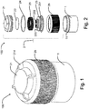
- Fig. 2 shows the different parts of the container assembly 100 in a first embodiment.
- the cover comprises a seal 22 in the form of a foil.
- the seal may also be a film, a membrane, a polymer, a composite material or glass.
- the top member 21 is made of a polymer material, but may be made of other materials such as glass.
- the cover 2 further comprises a packing 24 in the form of an O-ring for sealing the connection between the ring member 26 and the top member 21. Other sealing means may be used.
- resilient means 25 in the form of a spring positioned, for urging the punching or puncturing member 23 away from the seal 22.
- the resilient means 25 may be made of another resilient material such as rubber or it may be in the form of flexible rods positioned around the circumference of the punching or puncturing member 23 or inside the top member 21 along the circumference of the receptacle 211.
- the rods may be made of a polymer or a metal.
- the resilient means 25 may be integrated with either the top member 21 or the punching or puncturing member 23.
- the punching or puncturing member 23 in the form of a punch or a plunger is provided with apertures 232 in an area of the punching or puncturing member 23 that is adapted to enter the receptacle 211.
- the apertures 232 contribute to facilitating a fluid communication between the receptacle and the container 1.
- the punching member or puncturing 23 may also, or alternatively, be provided with apertures along flange 233, which is not intended to enter the receptacle 211.
- the punching or puncturing member 23 is hollow but it may also be solid and provided with one larger aperture or several smaller apertures for facilitating a fluid communication between receptacle 211 and the container 1.
- the receptacle 211 is either almost filled by the punching or puncturing member 23 or the connection between the receptacle 21 and the container 1 is sealed off when the punching or puncturing member 23 has reached its terminal position. This prevents the preserving agent from becoming separated from the tissue sample. Only a minimal part or nothing of the preserving agent can flow back into the receptacle 211 and into a space that is not reachable to the tissue sample, because the tissue sample may be larger than the provided apertures.
- the container assembly 100 comprises the container 1 adapted to engage with ring member 26.
- the engagement between the two can either be done via threads or via a press on cover, by pressing a resilient circumferential flange on the ring member 26 over a flange or other projections on the container 1 or vice versa.
- the ring member 26 is in this embodiment used for holding the container 1 and the top member 21 together and it contributes to controlling how far the top member 21 may be pushed down.
- the container 1 and/or the cover 2 may be provided with a transparent part for viewing inside the container 1 to see if a tissue sample is in the container 1 or if the seal 22 has been broken and the preserving agent is in the container 1.
- the container 1 and the cover 2 may be provided with a locking mechanism to prevent tampering with the tissue sample on the way from the hospital to the laboratory.
- the locking mechanism may be of a kind that may only be opened by the laboratory personnel or it may be an indicator showing if the assembly 100 has been opened.
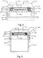
- Fig. 3 shows a close up view of an embodiment of the cover 2 in an assembled state.
- the top member 21 is provided with the receptacle 211 inside the top member 21 in the embodiment shown.
- the top member 21 is further provided with engagement means in the form of indentations 213. These are adapted to engage with projections 261 provided on the ring member 26. The engagement between the two retains the top member 21 in position as well as provides a safety margin of how far down the top member 21 may be pushed. If such movement limiting means was not present it would be possible to accidentally press the top member 21 and break the seal 22.
- the ring member 26 is provided with projection(s) 262 that keep(s) the punching or puncturing member 23 in place.
- the punching or puncturing member 23 is provided with threads 231 that are adapted to engage with threads 212 inside the top member 21. These make sure that the punching or puncturing member 23 cannot merely be pushed from below, such that the seal 22 breaks unintentionally.
- the top member 21 is advanced such that the seal 22 breaks.
- the top member 21 must be turned at the same time the top member 21 is being pushed from above simultaneously with the punching or puncturing member 23 being pushed from below.
- the punching or puncturing member 23 is being pushed from below by the container 1.
- the cover 2 and the container 1 is preferably fluid tightly coupled.
- the receptacle 211 is tapered such that the opening of the receptacle 516 is wider than the bottom 215.
- the receptacle may be other shapes such as cylindrical, pyramid shaped polygonal or other shapes.
- the punching or puncturing member may have the same shape.
- the receptacle in the cover may be filled with a preserving agent at the site where the cover is being manufactured or at least before the cover is delivered to the user.
- the receptacle may be filled with a preserving agent through the opening, which is later sealed off by the seal.
- the broken line encircles the volume 110 that does not change during breaking of the seal 22.
- the volume 110 is defined by the interior of the outer walls of the container assembly 100. This is the interior wall of the top member 21, the ring member 23 and the container 1. Where the parts overlap, it is the parts being the most interior that define the volume.
- the top member 21 has been pushed down as can be seen on the engagement between the projection 261 and the indentation 213.
- the punching or puncturing member 23 is ready to engage with the top member 21.
- By turning the top member 180-360 degrees the punching or puncturing member is forced through the seal and the seal is broken.
- the seal 22 is broken from below meaning that the punching or puncturing member 23 is outside the receptacle 211 before the seal 22 is broken.
- the top member may be turned more or less to break the seal 22 and to reach its terminal position.
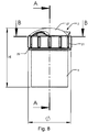
- Fig. 6 shows the punching or puncturing member 23 in the terminal position.
- the top part of the punching or puncturing member 23 above the flange 233 fits exactly into the receptacle 211.
- the top part of the punching or puncturing member may be smaller or bigger than the receptacle 211.
- the punching or puncturing member 23 supports the seal 22 after the seal 22 has been broken.
- the seal 22 might also be of such a kind that upon puncturing the seal draws out to the sides, leaving nothing but a ring of sealing material along the edge of the opening of the receptacle 216.
- the space that is left when the punching or puncturing member 23 has reached its terminal position is preferably less than 1/20 of the space in the receptacle from opening 216 to bottom 215 or the distance from the bottom of the receptacle 215 to the punching or puncturing member 23 is less than 1 mm.
- the figures 1-6 show the different positions or states that the container assembly may have.
- a cover including a top member with a receptacle and punching or puncturing member.
- the receptacle is filled with a preserving agent and the receptacle is sealed.
- a tissue sample (not shown) is placed in the possibly empty container and the cover is brought into engagement with the container.
- the top member is pushed down and in fig. 6 the punching or puncturing member is displaced by engaging engagement means of the punching or puncturing member with engagement means on the top member. The seal is consequently broken or punctured and the preserving agent is allowed to enter into the container.
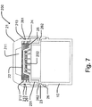
- Fig. 7 shows a container assembly in a second embodiment.
- the second embodiment works as described for the first embodiment and the features with the same reference number are the same.
- the difference here is that the container 10 is extending up into the punching or puncturing member 23.
- the punching or puncturing member 23 thereby has the option to rest on the projection 262 on the container or on the edge of the container. So that it is either the projection 262 that pushes the punching or puncturing member 23 up, or it is the edge of the container.
- Figs. 8-11 shows a third embodiment of the invention.
- the assembly comprises a container 1 and a cover 2, the cover 2 comprising a protective cap 27 and a top member 21.
- the purpose of the protective cap 27 is to secure that the membrane (see figs.9 and 10 ) is not pressed unintentionally.
- the protective cap 27 may be pivotable or removable.
- the top member 21 is provided with projections 29 for an easy grip and is removed from the container 1 by turning.
- the diameter ⁇ of this embodiment is 33 mm, but may be smaller or bigger.
- the height H is 47 mm, but may be smaller or bigger.
- the receptacle 211 may be higher such that more preserving agent may be contained.
- the receptacle 211 and the container 1 should preferably be able to contain about 20 ml preserving agent, respectively.
- fig. 9 the assembly is in the first position and in fig. 10 in the second position.
- the cross section in figs. 9-10 is taken along the line A-A as shown in fig. 8
- fig 11 is a cross section along the line B-B also shown in fig 8 .
- the container 1 is adapted to receive a tissue sample 45, and the cover comprises a top member 321.
- a separator 31 is provided between the seal 22 and the bottom 13 of the container. In this way, in a mounted state with the cover attached the container 1, the container 1 is separated into two spaces, a first 11 and a second 12 space. Even though the spaces 11, 12 are separated does not necessarily mean that the separator 31 and the container 1 are fluid tightly sealed. Fluid may be prevented from bypassing the separator 31.
- Fluid may also bypass the separator 31 instead of traveling though the separator 31.
- the inner circumference of the container 1 is of substantially same size as the outer circumference of the separator 31, but the inner circumference of the container 1 may be slightly bigger than the outer circumference of the separator 31.
- the top member 321 is provided with engagements means 324, such as threads, for engagement with the container 1.
- the container 1 is likewise provided with engagement means 325, here in the form of threads for engagement with the corresponding threads on the top member 321.
- the engagement between the top member 321 and the container 1 may alternatively be accomplished by means of a snap closure.
- the top member 321 is provided with engagement means 326 for engagement with the puncturing member 323.
- the engagement means 326 is in the form of four slits in a hollow cylindrical shape that is adapted to receive the puncturing member 323.
- the cylindrical shape may be solid and/or the number of slits may be varied.
- Engagement means in the form of a snap lock may be provided instead.
- top member 321 may be provided with engagement means 327 for engagement with engagement means 328 provided on the inner side of the separator 31.
- engagement means 327, 328 may be in the form of threads or a snap closure.
- the membrane 28 On top of the top member 321 the membrane 28 is positioned. In fig. 9 it has a substantially convex shape and in fig. 10 it has a substantially concave shape. When the pressure is removed from the membrane 28, the membrane 28 will keep its concave shape. This allows personnel to see from above if the preserving agent has been released. As the container 1 is preferably see-through, it may also be seen through the container 1 if the preserving agent has been released.
- the membrane 28 may be a spring membrane that automatically bounces back to its first position.
- the puncturing member 323 is activated by pressing the membrane 28. Thereby the puncturing member 323 is displaced along the longitudinal axis of the assembly, and the seal 22, separating the receptacle 211 from the container 1, is ruptured or broken.
- the puncturing member 323 is provided with teeth 329 for piercing the seal 22.
- the puncturing member 323 is made of a polymer material, but may also be made of metal or other suitable materials.
- An additional piercing element 330 for breaking through the seal 22 is provided, but may be dispensed with.
- the seal 22 may be a foil, a film or a polymer membrane.
- the separator 31 is adapted to hang from the cover 2. At the bottom 311 of the separator 31 a grid is provided. The separator 31 should be able to let the preserving agent through, and while at the same time ensuring that the seal 22 does not enter the container 1 and securing that the tissue sample 45 does not migrate into the receptacle 211 during transport.
- the apertures 291 in the grid in the separator 31 are squares, each approx. 1 mm in transverse size, but may be smaller or bigger, circular or polygon-shaped.
- the grid is permeable for a liquid with a surface tension similar to that of water. Another kind of permeable membrane may also be used.
- the separator 31 may be provided with apertures elsewhere, such as in the walls of the separator 31.
- the separator 31 is not a container for the tissue sample such as a cassette, but instead separates the container 1 in two interconnected spaces.
- the second space 12 and/or the bottom of the container 1 is adapted to receive the tissue sample 45.
- the first space 11 may also be positioned in the cover 2. Referring to figs.
- the separator 31 is furthermore provided with a conduit 30 with an opening or air inlet at the bottom of the separator 31 and an opening or an air outlet positioned at a distance from the air inlet.
- the air outlet is positioned such that when the seal 22 has been broken and the preserving agent has left the receptacle 211, the preserving agent may not pass the grid due to the smallness of the apertures and the surface tension of the agent, without for example shaking the assembly.
- the permeability of the grid can be increased by means of the conduit 30 that allows air in the container 1 to bypass the preserving agent through the conduit 30 and thereby letting the preserving agent pass through the apertures 291 in the grid.
- the opening or air outlet is therefore positioned such that it is above the level of the preserving agent when the seal 22 has been broken.
- Two conduits 30 are provided in this embodiment, but one of more than two conduits 30 and other shapes of conduits may be provided instead.
- the separator 31 or at least the grid is blue or another colour of contrast to a tissue sample. This makes it easier to see a tissue sample in case it clings to the separator 31.
- the separator may be other colours.
- the space 12 for the tissue sample 45 is positioned below the separator 31.
- the assembly may be provided with a tracking device such as an RFID (radio frequency identification) tag, such that the sample can be tracked from collection to test in a laboratory.
- the sample 45 need not be covered by the preserving agent at all times, since the fumes in the container 1 will usually be enough to preserve the sample 45.
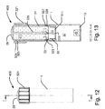
- Figs. 12 and 13 show a fourth embodiment of the invention in the form of container assembly 400.
- Fig. 13 shows a cross section of the assembly along the line A-A as shown in fig. 12 .
- All the features and functions present in the third embodiment are likewise present in the fourth embodiment where the same reference numbers indicate similar features.
- the difference between the third and the fourth embodiment is that the fourth embodiment is higher and is able to contain around 20 ml of formalin or other preserving agent both in the receptacle 211 and in the container 1.
- the conduit(s) 30 has in this embodiment not been made longer as it takes some time before the preserving agent passes the separator 31 and thereby the conduit(s) 30 will still be above the level of the preserving agent when the seal 22 has been broken.
- the conduit(s) 30 may be made longer, such as between 2-5 cm long. Any size of container able to contain between about 5-50 ml of preserving agent can be imagined.
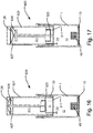
- Figs. 14 and 15 show a fifth embodiment of the invention in the form of container assembly 500. All the features and functions present in the third and fourth embodiments are likewise present in the fifth embodiment where the same reference numbers indicate similar features.
- the assembly 500 In fig. 14 the assembly 500 is in a first position and in fig. 15 the assembly is in a second position.
- the container assembly 500 further comprises a removable cap 528 provided with gripping parts 548. The cap 528 protects the membrane 28 from pressure during transport.
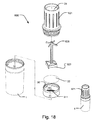
- Figs. 16 - 18 show a sixth embodiment of the invention in the form of container assembly 600.
- the container assembly 600 differentiates itself among others from the third embodiment in that the top member 621 is taller and is able to contain more preserving agent.
- the punching or puncturing member 323 is also taller and is provided with a cross shaped or T-shaped projection 626 at the top.
- the projection 626 rests at a circumferential flange 627 provided on the top member 621. Thereby when the membrane 28 is pushed down, the projection is forced pass the circumferential flange 627 upon which it rested in its initial position.
- the circumferential flange 627 or the projection 626 may have resilient properties, which allow the projection 626 to pass the circumferential flange 627.
- the projection 626 may be tapered such that it can be pressed pass the flange 627 more easily.
- the circumferential flange 627 may also be in the form of circumferential projections that are not connected along the whole circumference.
- the top member 621 is connectable to the container 1 such that the exterior of the top member 621 engages with the interior of the container 1. It may also be vice versa.
- the top member 621 and container 1 may be provided with engagement means in form of threads.
- the separator 31 is provided with conduit(s) 31 in the form of segments. By extending the wall of the conduit(s) across the separator 31 as a chord, the separator 31 gets more rigid.
- the conduit(s) 30 do(es) not extend above the top edge of the separator 31, but may do so in other embodiments.
- the top member 621 extends above the highest point of the membrane 28 in a first position, thereby protecting the membrane 28 from pressure when no protective cap is provided.
- the highest point in this embodiment is the center of the membrane.
- the sixth embodiment may further comprise any of the features from the third, fourth and fifth embodiment.
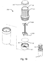
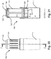
- Figs. 19-21 show a seventh embodiment of the invention.
- the container assembly 700 is additionally provided with a cap 728.
- the top member 721 does not extend beyond the highest point of the membrane 28 as it does in the sixth embodiment.
- the seventh embodiment may contain any of the features from the third, fourth, fifth and sixth embodiment.
- broken is meant that a hole has been created in the film or seal where either the preserving agent may flow out or particles or contaminants from the outside may enter.
- cover includes all means that cover the opening of a container.
- separatator is used for a member used to separate the seal from a potential tissue sample placed in the container.
- the separator also functions as the punching or puncturing member, such that the separator and the punching member form one element, while in other embodiments the puncturing member and the separator are separate elements.
- the word “container” is generally used about the container or space that is adapted to contain the tissue sample.
- the container assembly may be of industrial size where the container is able to contain at least 1 L or less than 5 L, 10 L, 100 L, 1000 L or more.
- the container may contain a substance which is to be mixed with a second substance with less of a volume.
- the cover or lid may be able to contain the second substance, with a volume of less than 5 ml, 10 ml, 30 ml, 50 ml, 100 ml or more than 100 ml, which is to be mixed with the substance in the container.
- the second substance may be a toxic or volatile substance or a substance where it is important that the exact amount of substance is entered into the container.
- This larger sized container assembly may have the same features as the first, second, third or fourth embodiment. Any feature of these embodiments may be applied independently of each other to this larger sized container assembly.
Description
- The present invention relates to a container assembly, more specifically to a container assembly comprising: a container configured to store a tissue sample, said container comprising a bottom, a cover adapted to engage with said container, said cover comprising: a top member comprising a receptacle, said receptacle containing a preserving agent, a seal for sealing off said receptacle, a puncturing member configured to break said seal by displacement of said puncturing member, where the container assembly has a first and a second position.
- The invention further relates to a method of preserving a tissue sample.
- Container assemblies for releasing an agent into a container at a desired point in time are well known and come in many shapes and sizes, both within the industry as well as within consumer goods.
- In hospitals and clinics containers or Petri dishes are used for collecting and storing tissue samples, such that after a tissue sample has been taken from a patient, the tissue sample is placed in a container, and a preserving agent, often formalin, is subsequently filled in the container before the container is closed and sent off to a laboratory for analysis. Here the container is usually opened in a fume cupboard as formalin and other preserving agents are toxic to inhale. The problem with this is that in the hospital the personnel taking the tissue sample, have to handle a preserving agent on a daily basis when filling the container. Usually a formalin dispenser station or a dispenser mountable on the container temporarily is used. After the formalin has been dispensed into the container, the lid is mounted on the container. Handling of a preserving agent this way may result in spillage and inhalation. Inhalation and other exposures constitute is a health hazard and handling of formalin and other preserving agents should be carried out with great care.
-
WO2004/000678 describes different embodiments of mixing vials, in particular the embodiment depicted infigs. 6A-B show a mixing vial where a rigid rod is pressed through a supplemental container and the dilutant is entered into the container. -
US 5,152,965 describes an assembly of containers, comprising a reagent vial and a container adapted to engage with an adapter assembly positioned between the two. The reagent vial contains a reagent to be mixed with a reagent diluent in the container. The adapter assembly comprises a coupler and a hollow plunger. The reagent vial is engageable with the coupler in a first position and is advanceable into a second position relative to the adapter assembly such that the hollow plunger thereof displaces the seal of the reagent vial permitting the reagent to flow through the hollow plunger to mix with diluent in the container. - The advancement of the coupler results in an increased pressure in the container, which is undesirable as the increased pressure might result in a spillage of the content in the container, when the adapter assembly is removed from the container.
-
WO2008/040812 describes a receptacle configured to receive a volume of preserving agent, and a lid containing the preserving agent and being adapted to be coupled to a tissue storage container. The preserving agent is entered into the lid through a one way valve. The lid further comprises a membrane with a number of holes. A plastic disc containing an equal amount of holes is placed between the receptacle and the membrane in the lid. When the holes are brought into alignment, e.g. by twisting the lid, the preserving agent flows into the receptacle. This requires that the container assembly is oriented such that the cover facing upwards, thereby allowing the preserving agent to flow into the container assisted by gravity. -
US 2009/0104692 describes a container for storing a biological sample.US2010/0101340 describes a sample collecting device andUS 4,353,868 describes a specimen collecting device in particular for a swab. - The object of the present invention is to provide a container assembly where the risk of spillage and evaporation is considerably reduced and risk of the sample getting stuck to the cover is eliminated.
- In a first aspect, this is achieved by providing a container assembly of the kind mentioned in the introduction, which is furthermore characterized in that in the first position the container is isolated from the receptacle, and in the second position fluid communication is provided between the receptacle and the container, and that the container assembly comprises a separator positioned between the seal and the bottom of the container, and the separator is provided with at least one aperture adapted to provide a fluid passage between the receptacle and the container.
- By positioning the separator between the receptacle and the bottom of the container, it is ensured that the tissue sample does not get stuck to the top member or the puncturing means and at the same time that the seal does not interfere with the tissue sample. The tissue sample will usually be positioned at the bottom of the container.
- According to a preferred embodiment the container assembly further comprising a space between the separator and the seal, the separator being provided with a conduit adapted to provide a fluid passage between the space and the container. This enables air from the container to travel upwards and thereby making it easier for the preserving agent to enter the container through the separator.
- The conduit may have an opening positioned above the level of the preserving agent after the seal has been broken. Thereby the air in the container below the separator bypasses the preserving agent, making it easier for the preserving agent to enter the container below the separator.
- The cover may constitute a lid. Instead of having to remove the cover after having released the content in the receptacle, the cover may stay on the container and function as a lid, making it easy to transport.
- The cover may comprise a membrane having a substantially convex shape in the first position and a substantially concave shape in the second position. This membrane preferably covers the puncturing member. The different shapes of the membrane in the first and second position, makes it possible for the personnel to see from above if the seal has been broken.
- The cover may comprise a protective cap for covering the membrane. Thereby it is ensured that the membrane and thereby the puncturing member is not pressed accidentally and the seal is not broken when it is not intended to.
- The container assembly may comprise a tracking device, such that the tissue sample can be tracked from where it was taken all the way to the laboratory. The container assembly may also comprise a temperature tracker, such that it is possible to see if the tissue has been subjected to heat or cold, which may affect the tissue sample and consequently the results of a test.
- The puncturing member may be provided with at least one aperture, for providing a passage between the space and the container. This eases the flow of the preserving agent into the container. The preserving agent may flow around the puncturing member as well.
- The separator may comprise a bottom and, engagement means for engagement with corresponding engagement means of the cover, such that the bottom of the separator is prevented from contacting the bottom of the container. The tissue sample does therefore not risk being pressed or squashed when in the container and when the cover is removed for entering or taking out the tissue sample, the separator stays connected to the cover and does not get in the way when handling the tissue sample. The engagement means may for example be threads or a snap closure.
- An outer diameter of the separator may be substantially equal to an inner diameter of the container, such that the separator and the container substantially fit together and little fluid may bypass the separator.
- The seal may be selected from a group consisting of a film, a foil, a membrane and a polymer. These are all materials that are suitable to be either punctured or cut or in any way penetrated, such that the preserving agent may escape.
- A part of the container assembly may comprise a transparent part for viewing inside the container. This enables the user of the container assembly to visually inspect the sample to see if a proper preservation has been carried out or whether the preserving agent has been released from the receptacle into the container.
- The assembly may be provided with an indicator for indicating whether the seal has been broken. This can be seen as an indicator of whether the content of the receptacle has been compromised, if the seal has been damaged contaminants might enter the receptacle, or whether the content of the receptacle has been released and thereby alert the user. If the content has been released, the user knows that the container should not be opened without taking different safety measures, such as opening the container in a fume cupboard.
- The separator is preferably a contrast colour, such as blue, to a colour of the tissue. This makes it easier the see the tissue sample if it gets stuck to the separator during transport e.g. to the laboratory.
- The cover may be adapted to be locked to the container. This secures that there cannot be any tampering with the tissue samples.
- According to another embodiment the container assembly may comprise a container for storing a tissue sample, a cover adapted to engage with the container, wherein the cover comprises: a top member comprising a receptacle, wherein the receptacle contains a preserving agent, a seal for sealing off said receptacle, a punching or puncturing member for breaking said seal wherein the seal is broken by displacing the punching or puncturing member, a volume where the volume is defined by the interior of the outer walls of the container assembly, wherein the punching or puncturing member is provided with engagement means adapted to engage with corresponding engagement means provided on the top member, such that the position of the punching or puncturing member is adjustable independently of the orientation of the container assembly, the container assembly has a first and a second position, wherein in the first position the container is separate from the receptacle, and in the second position fluid communication is provided between the receptacle and the container, wherein the volume in the first position is the same as the volume in the second position. By not changing the volume of the container assembly, the pressure inside the container remains the same and thereby the risk of spillage when opened is considerably reduced.
- The punching or puncturing member may be adapted to support the seal after the seal has been broken. By letting the punching or puncturing member support the seal the risk of parts of the seal slipping into the container after the seal has been broken, and mixing with the content here, is reduced.
- The cover may further comprise a ring member adapted to engage with said container. This ensures that the cover is connectable to the container.
- The seal may be broken from outside of the receptacle. By not having to mount any punching or puncturing means within the receptacle, the risk of spillage during mounting of the cover is reduced and the risk of any contaminants getting into the receptacle is reduced, and the shelf life of the assembly is increased.
- The punching or puncturing member and the receptacle may be adapted to substantially fit together. This means that they are shaped such that they leave minimum room for anything being positioned between the two, except for the broken seal, when the punching or puncturing member has been displaced to its terminal position. The terminal position is defined as a position where the punching or puncturing member cannot be displaced further from its initial position. This reduces the risk of any preserving agent flowing from the container back into the receptacle behind the punching or puncturing member, thereby separating the tissue sample from the preserving agent.
- At least a part of the space in the receptacle may form part of the space in the container, when the cover is mounted on the container and the seal has been broken. This means that the punching or puncturing member is displaced such that when the seal has been broken, the punching or puncturing member functions as a new separator between the receptacle and the container and at least some of the space in the receptacle now forms part of the container where the tissue sample may be present.
- The punching or puncturing member may only be able to advance when the cover is mounted on the container. This secures that the seal is not accidentally broken, and the preserving agent may leak.
- The punching or puncturing member may only be able to advance when the top member is pushed down simultaneously with being turned. This secures that even when the top member is mounted on the container, the seal is not accidentally broken.
- The cover may comprise resilient means for urging the punching or puncturing member away from the receptacle. This enables the opening of the cover by simultaneously pushing and turning of the cover. Additionally it contributes to ensuring that the seal does not rest on the punching or puncturing member and thereby increasing the risk of unintentionally breaking the seal.
- The receptacle may comprise an opening and a bottom, wherein the receptacle may be tapered towards the bottom. By making the receptacle tapered, a faster release of the preserving agent is obtained and it is not possible for any of the preserving agent to not be released into the container when the seal is broken. The receptacle may also be straight or cylindrical.
- According to a second aspect a method of preserving a tissue sample in the container assembly, comprises the steps of: providing a container, filled with a preserving agent and sealed off by a seal, a puncturing member and a separator , placing a tissue sample in said container, engaging said cover with the container thereby positioning said separator between the seal and the bottom of the container, displacing the puncturing member whereby said seal is broken and the preserving agent is allowed to enter into the container through the separator.
- The puncturing member is preferably displaced by pressure on the puncturing member.
- A different method of providing a container assembly for containing a tissue sample may be provided, comprising the steps of: providing a container, providing a cover including a top member with a receptacle and punching or puncturing member, filling said receptacle with a preserving agent, sealing said receptacle with a seal, placing a tissue sample in said container, engaging said cover with the container, displacing the punching or puncturing member by engaging engagement means of the punching or puncturing member with engagement means on the top member of the cover, whereby the seal is broken and the preserving agent is entered into the container.
- Any features from the first aspect may be incorporated into the second aspect, and vice versa.
- In the following, the invention will be described in further detail with reference to the drawings in which:
-
Fig. 1 shows a perspective view of the container assembly in a first embodiment, -
Fig.2 shows an exploded view of the container assembly shown inFig. 1 , -
Fig. 3 shows a detailed view of a cross section of the cover in the first embodiment, -
Fig. 4 shows a cross section of the container assembly in a first position in the first embodiment, -
Fig. 5 shows a cross section of a first embodiment of the container assembly in a first position with the lid slightly pushed down, -
Fig. 6 shows a cross section of a first embodiment of the container assembly in a second position where the seal has been broken, and -
Fig. 7 shows a view corresponding toFig. 3 of the container assembly in a second embodiment, -
Fig. 8 shows a perspective view of the container assembly in a third embodiment, -
Fig. 9 shows a cross section of the container assembly in a first position in the third embodiment, -
Fig. 10 shows a cross section of the container assembly in a second position in the third embodiment, -
Fig. 11 shows a cross section of the container assembly in the third embodiment, -
Fig. 12 shows a perspective view of the container assembly in a fourth embodiment, -
Fig. 13 shows a cross section of the container assembly in a first position in the fourth embodiment. -
Fig. 14 shows a cross section of the container assembly in a first position in a fifth embodiment. -
Fig. 15 shows a cross section of the container assembly in a second position in a fifth embodiment. -
Fig. 16 shows a cross section of the container assembly in a first position in a sixth embodiment. -
Fig. 17 shows a cross section of the container assembly in a second position in a sixth embodiment. -
Fig. 18 shows an exploded view the container assembly in a sixth embodiment as well as the container assembly in an assembled state. -
Fig. 19 shows an exploded view the container assembly in a seventh embodiment as well as the container assembly in a perspective view in an assembled state. -
Fig. 20 shows the container assembly in an assembled state in a seventh embodiment. -
Fig. 21 shows a cross section of the container assembly in a first position in a seventh embodiment. - Like reference numbers refer to like features throughout the drawings.
-
Fig. 1 shows a container assembly generally designated 100 and comprising acontainer 1 for containing a tissue sample and acover 2 in an assembled state. In the embodiment shown thecover 2 comprises aring member 26, which is grooved for a firmer grip, and atop member 21. Thering member 26 may be provided with a rubber surface or simply with a smooth surface instead. Thetop member 21 is provided with projection(s) 214 for making it easier to get a hold on thetop member 21, when thetop member 21 is to be turned. The cover constitutes a lid, making the container assembly easy to transport. In the embodiment shown the container assembly is in an assembled state maximum 35 mm thick or deep or long on one of its sides, which makes it possible to send it in a letter. The container assembly may also be a maximum of 20 mm on one of its sides, 25 mm on one of its sides or 50 mm on one of its sides. The container assembly may be larger on one of its sides, or even smaller on one of it sides. The receptacle in this embodiment is adapted to contain 10 ml of preserving agent, such as formalin. The receptacle may be able to contain a different amount of preserving agent, such as less than 15 ml, less than 20 ml, less than 25 ml, less than 50 ml, less than 100 ml or less than 10 ml preserving agent or more than 100 ml of preserving agent. Thecontainer 1 is at least able to contain the corresponding amount of preserving agent as well as a tissue sample. A tissue sample may take up up to 1 cm3, but is likely to be smaller, down to 1 mm3. The tissue sample may be able to be covered by the preserving agent no matter the orientation of the assembly. -
Fig. 2 shows the different parts of thecontainer assembly 100 in a first embodiment. In addition to thetop member 21, the cover comprises aseal 22 in the form of a foil. The seal may also be a film, a membrane, a polymer, a composite material or glass. Thetop member 21 is made of a polymer material, but may be made of other materials such as glass. In the embodiment shown thecover 2 further comprises a packing 24 in the form of an O-ring for sealing the connection between thering member 26 and thetop member 21. Other sealing means may be used. - Between a punching or puncturing
member 23 and thetop member 21 is resilient means 25 in the form of a spring positioned, for urging the punching or puncturingmember 23 away from theseal 22. In other embodiments the resilient means 25 may be made of another resilient material such as rubber or it may be in the form of flexible rods positioned around the circumference of the punching or puncturingmember 23 or inside thetop member 21 along the circumference of thereceptacle 211. The rods may be made of a polymer or a metal. The resilient means 25 may be integrated with either thetop member 21 or the punching or puncturingmember 23. - In this embodiment the punching or puncturing
member 23 in the form of a punch or a plunger is provided withapertures 232 in an area of the punching or puncturingmember 23 that is adapted to enter thereceptacle 211. Theapertures 232 contribute to facilitating a fluid communication between the receptacle and thecontainer 1. The punching member or puncturing 23 may also, or alternatively, be provided with apertures alongflange 233, which is not intended to enter thereceptacle 211. The punching or puncturingmember 23 is hollow but it may also be solid and provided with one larger aperture or several smaller apertures for facilitating a fluid communication betweenreceptacle 211 and thecontainer 1. By making the punching or puncturingmember 23 solid and making it fit together in shape with thereceptacle 211 or only providing the punching or puncturingmember 23 with aperture(s) along theflange 233, thereceptacle 211 is either almost filled by the punching or puncturingmember 23 or the connection between thereceptacle 21 and thecontainer 1 is sealed off when the punching or puncturingmember 23 has reached its terminal position. This prevents the preserving agent from becoming separated from the tissue sample. Only a minimal part or nothing of the preserving agent can flow back into thereceptacle 211 and into a space that is not reachable to the tissue sample, because the tissue sample may be larger than the provided apertures. - Finally the
container assembly 100 comprises thecontainer 1 adapted to engage withring member 26. The engagement between the two can either be done via threads or via a press on cover, by pressing a resilient circumferential flange on thering member 26 over a flange or other projections on thecontainer 1 or vice versa. Thering member 26 is in this embodiment used for holding thecontainer 1 and thetop member 21 together and it contributes to controlling how far thetop member 21 may be pushed down. - The
container 1 and/or thecover 2 may be provided with a transparent part for viewing inside thecontainer 1 to see if a tissue sample is in thecontainer 1 or if theseal 22 has been broken and the preserving agent is in thecontainer 1. Thecontainer 1 and thecover 2 may be provided with a locking mechanism to prevent tampering with the tissue sample on the way from the hospital to the laboratory. The locking mechanism may be of a kind that may only be opened by the laboratory personnel or it may be an indicator showing if theassembly 100 has been opened. -
Fig. 3 shows a close up view of an embodiment of thecover 2 in an assembled state. - As shown in detail in this figure, the
top member 21 is provided with thereceptacle 211 inside thetop member 21 in the embodiment shown. Thetop member 21 is further provided with engagement means in the form ofindentations 213. These are adapted to engage withprojections 261 provided on thering member 26. The engagement between the two retains thetop member 21 in position as well as provides a safety margin of how far down thetop member 21 may be pushed. If such movement limiting means was not present it would be possible to accidentally press thetop member 21 and break theseal 22. Additionally thering member 26 is provided with projection(s) 262 that keep(s) the punching or puncturingmember 23 in place. In the embodiment shown the punching or puncturingmember 23 is provided withthreads 231 that are adapted to engage withthreads 212 inside thetop member 21. These make sure that the punching or puncturingmember 23 cannot merely be pushed from below, such that theseal 22 breaks unintentionally. When it is desired to break theseal 22, thetop member 21 is advanced such that theseal 22 breaks. In this embodiment thetop member 21 must be turned at the same time thetop member 21 is being pushed from above simultaneously with the punching or puncturingmember 23 being pushed from below. The punching or puncturingmember 23 is being pushed from below by thecontainer 1. Before breaking theseal 22 thecover 2 and thecontainer 1 is preferably fluid tightly coupled. - In the embodiment shown, the
receptacle 211 is tapered such that the opening of the receptacle 516 is wider than the bottom 215. The receptacle may be other shapes such as cylindrical, pyramid shaped polygonal or other shapes. Correspondingly the punching or puncturing member may have the same shape. - In all of the embodiments the receptacle in the cover may be filled with a preserving agent at the site where the cover is being manufactured or at least before the cover is delivered to the user. The receptacle may be filled with a preserving agent through the opening, which is later sealed off by the seal.
- From the embodiment in
fig. 4 it can be seen how the punching or puncturingmember 23 rests on the edge of thecontainer 1 and by mounting thecover 2 on thecontainer 1 the punching or puncturingmember 23 is pushed slightly upwards. This makes sure that the punching or puncturingmember 23 is only able to advance when thecover 2 is mounted on thecontainer 1. The engagement means 231 and 212 is still not able to engage if thetop member 23 were turned. In this embodiment thetop member 21 must be pushed down as well. This added security that thetop member 21 must be pushed down as well to break theseal 22 may be left out. - Instead of advancing the engagement of the engagement means on the
top member 212 with the engagement means on the punching or puncturingmember 231, by turning thetop member 21, it may be possible to have a sudden release of the preserving agent, where theseal 22 is broken by pushing thetop member 21 down without turning thetop member 21. In this case theindentation 213 extends further upwards and does not stop theprojection 261 until after theseal 22 has been broken. - Between the
ring member 26 and the container 1 a further packing (not shown) may be provided for added sealing between the two. - The broken line encircles the
volume 110 that does not change during breaking of theseal 22. Thevolume 110 is defined by the interior of the outer walls of thecontainer assembly 100. This is the interior wall of thetop member 21, thering member 23 and thecontainer 1. Where the parts overlap, it is the parts being the most interior that define the volume. - In
fig. 5 thetop member 21 has been pushed down as can be seen on the engagement between theprojection 261 and theindentation 213. The punching or puncturingmember 23 is ready to engage with thetop member 21. By turning the top member 180-360 degrees the punching or puncturing member is forced through the seal and the seal is broken. Theseal 22 is broken from below meaning that the punching or puncturingmember 23 is outside thereceptacle 211 before theseal 22 is broken. The top member may be turned more or less to break theseal 22 and to reach its terminal position. -
Fig. 6 shows the punching or puncturingmember 23 in the terminal position. The top part of the punching or puncturingmember 23 above theflange 233 fits exactly into thereceptacle 211. The top part of the punching or puncturing member may be smaller or bigger than thereceptacle 211. After the seal has been broken, it is positioned between thetop member 21 and the punching or puncturingmember 23, and theseal 22 is prevented from entering into thecontainer 1. The punching or puncturingmember 23 supports theseal 22 after theseal 22 has been broken. Theseal 22 might also be of such a kind that upon puncturing the seal draws out to the sides, leaving nothing but a ring of sealing material along the edge of the opening of thereceptacle 216. The space that is left when the punching or puncturingmember 23 has reached its terminal position is preferably less than 1/20 of the space in the receptacle from opening 216 tobottom 215 or the distance from the bottom of thereceptacle 215 to the punching or puncturingmember 23 is less than 1 mm. - The
figures 1-6 show the different positions or states that the container assembly may have. - In
fig. 1 -3 a container, a cover is provided including a top member with a receptacle and punching or puncturing member. Infig. 3 the receptacle is filled with a preserving agent and the receptacle is sealed. Infig. 4 a tissue sample (not shown) is placed in the possibly empty container and the cover is brought into engagement with the container. Infig. 5 the top member is pushed down and infig. 6 the punching or puncturing member is displaced by engaging engagement means of the punching or puncturing member with engagement means on the top member. The seal is consequently broken or punctured and the preserving agent is allowed to enter into the container. -
Fig. 7 shows a container assembly in a second embodiment. The second embodiment works as described for the first embodiment and the features with the same reference number are the same. The difference here is that thecontainer 10 is extending up into the punching or puncturingmember 23. The punching or puncturingmember 23 thereby has the option to rest on theprojection 262 on the container or on the edge of the container. So that it is either theprojection 262 that pushes the punching or puncturingmember 23 up, or it is the edge of the container. By making the container extend into the punching or puncturing member the personnel opening the container assembly is better protected from spillage as the wall above the level of preserving agent in the container is higher. -
Figs. 8-11 shows a third embodiment of the invention. Referring tofig. 8 , the assembly comprises acontainer 1 and acover 2, thecover 2 comprising aprotective cap 27 and atop member 21. The purpose of theprotective cap 27 is to secure that the membrane (seefigs.9 and 10 ) is not pressed unintentionally. Theprotective cap 27 may be pivotable or removable. Thetop member 21 is provided withprojections 29 for an easy grip and is removed from thecontainer 1 by turning. The diameter ø of this embodiment is 33 mm, but may be smaller or bigger. The height H is 47 mm, but may be smaller or bigger. Thereceptacle 211 may be higher such that more preserving agent may be contained. Thereceptacle 211 and thecontainer 1 should preferably be able to contain about 20 ml preserving agent, respectively. - In
fig. 9 the assembly is in the first position and infig. 10 in the second position. The cross section infigs. 9-10 is taken along the line A-A as shown infig. 8 , andfig 11 is a cross section along the line B-B also shown infig 8 . Thecontainer 1 is adapted to receive atissue sample 45, and the cover comprises atop member 321. Aseparator 31 is provided between theseal 22 and the bottom 13 of the container. In this way, in a mounted state with the cover attached thecontainer 1, thecontainer 1 is separated into two spaces, a first 11 and a second 12 space. Even though thespaces separator 31 and thecontainer 1 are fluid tightly sealed. Fluid may be prevented from bypassing theseparator 31. Fluid may also bypass theseparator 31 instead of traveling though theseparator 31. The inner circumference of thecontainer 1 is of substantially same size as the outer circumference of theseparator 31, but the inner circumference of thecontainer 1 may be slightly bigger than the outer circumference of theseparator 31. - Referring to
figs. 9-10 , thetop member 321 is provided with engagements means 324, such as threads, for engagement with thecontainer 1. Thecontainer 1 is likewise provided with engagement means 325, here in the form of threads for engagement with the corresponding threads on thetop member 321. The engagement between thetop member 321 and thecontainer 1 may alternatively be accomplished by means of a snap closure. Furthermore thetop member 321 is provided with engagement means 326 for engagement with the puncturingmember 323. The engagement means 326 is in the form of four slits in a hollow cylindrical shape that is adapted to receive the puncturingmember 323. The cylindrical shape may be solid and/or the number of slits may be varied. Engagement means in the form of a snap lock may be provided instead. Furthermore thetop member 321 may be provided with engagement means 327 for engagement with engagement means 328 provided on the inner side of theseparator 31. Hereby theseparator 31 stays attached to thecover 2 when thecover 2 is removed from thecontainer 1, e.g. for taking out a tissue sample. The engagement means 327, 328 may be in the form of threads or a snap closure. - On top of the
top member 321 themembrane 28 is positioned. Infig. 9 it has a substantially convex shape and infig. 10 it has a substantially concave shape. When the pressure is removed from themembrane 28, themembrane 28 will keep its concave shape. This allows personnel to see from above if the preserving agent has been released. As thecontainer 1 is preferably see-through, it may also be seen through thecontainer 1 if the preserving agent has been released. Themembrane 28 may be a spring membrane that automatically bounces back to its first position. The puncturingmember 323 is activated by pressing themembrane 28. Thereby the puncturingmember 323 is displaced along the longitudinal axis of the assembly, and theseal 22, separating thereceptacle 211 from thecontainer 1, is ruptured or broken. - In the embodiment shown, the puncturing
member 323 is provided withteeth 329 for piercing theseal 22. The puncturingmember 323 is made of a polymer material, but may also be made of metal or other suitable materials. An additional piercingelement 330 for breaking through theseal 22 is provided, but may be dispensed with. - The
seal 22 may be a foil, a film or a polymer membrane. - The
separator 31 is adapted to hang from thecover 2. At thebottom 311 of the separator 31 a grid is provided. Theseparator 31 should be able to let the preserving agent through, and while at the same time ensuring that theseal 22 does not enter thecontainer 1 and securing that thetissue sample 45 does not migrate into thereceptacle 211 during transport. - Referring to
fig. 11 , theapertures 291 in the grid in theseparator 31 are squares, each approx. 1 mm in transverse size, but may be smaller or bigger, circular or polygon-shaped. The grid is permeable for a liquid with a surface tension similar to that of water. Another kind of permeable membrane may also be used. Theseparator 31 may be provided with apertures elsewhere, such as in the walls of theseparator 31. Theseparator 31 is not a container for the tissue sample such as a cassette, but instead separates thecontainer 1 in two interconnected spaces. Thesecond space 12 and/or the bottom of thecontainer 1 is adapted to receive thetissue sample 45. Thefirst space 11 may also be positioned in thecover 2. Referring tofigs. 9-11 theseparator 31 is furthermore provided with aconduit 30 with an opening or air inlet at the bottom of theseparator 31 and an opening or an air outlet positioned at a distance from the air inlet. The air outlet is positioned such that when theseal 22 has been broken and the preserving agent has left thereceptacle 211, the preserving agent may not pass the grid due to the smallness of the apertures and the surface tension of the agent, without for example shaking the assembly. The permeability of the grid can be increased by means of theconduit 30 that allows air in thecontainer 1 to bypass the preserving agent through theconduit 30 and thereby letting the preserving agent pass through theapertures 291 in the grid. The opening or air outlet is therefore positioned such that it is above the level of the preserving agent when theseal 22 has been broken. Twoconduits 30 are provided in this embodiment, but one of more than twoconduits 30 and other shapes of conduits may be provided instead. Theseparator 31 or at least the grid is blue or another colour of contrast to a tissue sample. This makes it easier to see a tissue sample in case it clings to theseparator 31. The separator may be other colours. Thespace 12 for thetissue sample 45 is positioned below theseparator 31. The assembly may be provided with a tracking device such as an RFID (radio frequency identification) tag, such that the sample can be tracked from collection to test in a laboratory. Thesample 45 need not be covered by the preserving agent at all times, since the fumes in thecontainer 1 will usually be enough to preserve thesample 45. -
Figs. 12 and 13 show a fourth embodiment of the invention in the form ofcontainer assembly 400.Fig. 13 shows a cross section of the assembly along the line A-A as shown infig. 12 . All the features and functions present in the third embodiment are likewise present in the fourth embodiment where the same reference numbers indicate similar features. The difference between the third and the fourth embodiment is that the fourth embodiment is higher and is able to contain around 20 ml of formalin or other preserving agent both in thereceptacle 211 and in thecontainer 1. The conduit(s) 30 has in this embodiment not been made longer as it takes some time before the preserving agent passes theseparator 31 and thereby the conduit(s) 30 will still be above the level of the preserving agent when theseal 22 has been broken. The conduit(s) 30 may be made longer, such as between 2-5 cm long. Any size of container able to contain between about 5-50 ml of preserving agent can be imagined. -
Figs. 14 and 15 show a fifth embodiment of the invention in the form ofcontainer assembly 500. All the features and functions present in the third and fourth embodiments are likewise present in the fifth embodiment where the same reference numbers indicate similar features. Infig. 14 theassembly 500 is in a first position and infig. 15 the assembly is in a second position. In addition to similar features as those described in the third and/or fourth embodiments, thecontainer assembly 500 further comprises aremovable cap 528 provided withgripping parts 548. Thecap 528 protects themembrane 28 from pressure during transport. -
Figs. 16 - 18 show a sixth embodiment of the invention in the form ofcontainer assembly 600. Thecontainer assembly 600 differentiates itself among others from the third embodiment in that thetop member 621 is taller and is able to contain more preserving agent. The punching or puncturingmember 323 is also taller and is provided with a cross shaped or T-shapedprojection 626 at the top. Theprojection 626 rests at acircumferential flange 627 provided on thetop member 621. Thereby when themembrane 28 is pushed down, the projection is forced pass thecircumferential flange 627 upon which it rested in its initial position. Thecircumferential flange 627 or theprojection 626 may have resilient properties, which allow theprojection 626 to pass thecircumferential flange 627. Theprojection 626 may be tapered such that it can be pressed pass theflange 627 more easily. Thecircumferential flange 627 may also be in the form of circumferential projections that are not connected along the whole circumference. Thetop member 621 is connectable to thecontainer 1 such that the exterior of thetop member 621 engages with the interior of thecontainer 1. It may also be vice versa. Thetop member 621 andcontainer 1 may be provided with engagement means in form of threads. - Furthermore the
separator 31 is provided with conduit(s) 31 in the form of segments. By extending the wall of the conduit(s) across theseparator 31 as a chord, theseparator 31 gets more rigid. The conduit(s) 30 do(es) not extend above the top edge of theseparator 31, but may do so in other embodiments. - The
top member 621 extends above the highest point of themembrane 28 in a first position, thereby protecting themembrane 28 from pressure when no protective cap is provided. The highest point in this embodiment is the center of the membrane. - The sixth embodiment may further comprise any of the features from the third, fourth and fifth embodiment.
-
Figs. 19-21 show a seventh embodiment of the invention. In addition to the features in the sixth embodiment thecontainer assembly 700 is additionally provided with acap 728. Thetop member 721 does not extend beyond the highest point of themembrane 28 as it does in the sixth embodiment. The seventh embodiment may contain any of the features from the third, fourth, fifth and sixth embodiment. - By "broken" is meant that a hole has been created in the film or seal where either the preserving agent may flow out or particles or contaminants from the outside may enter.
- The term "cover" as used herein includes all means that cover the opening of a container. The term "separator" is used for a member used to separate the seal from a potential tissue sample placed in the container. In some embodiments the separator also functions as the punching or puncturing member, such that the separator and the punching member form one element, while in other embodiments the puncturing member and the separator are separate elements.
- The word "container" is generally used about the container or space that is adapted to contain the tissue sample.
- Furthermore, it is conceivable to make use of other configurations of the container assembly. It may be of industrial size where the container is able to contain at least 1 L or less than 5 L, 10 L, 100 L, 1000 L or more. The container may contain a substance which is to be mixed with a second substance with less of a volume. The cover or lid may be able to contain the second substance, with a volume of less than 5 ml, 10 ml, 30 ml, 50 ml, 100 ml or more than 100 ml, which is to be mixed with the substance in the container. The second substance may be a toxic or volatile substance or a substance where it is important that the exact amount of substance is entered into the container. This larger sized container assembly may have the same features as the first, second, third or fourth embodiment. Any feature of these embodiments may be applied independently of each other to this larger sized container assembly.
- In general, the features of the embodiments shown and described may be combined freely and no feature should be seen as essential unless stated in the independent claims.
Claims (15)
- Container assembly (300) comprising- a container (1) configured to store a tissue sample (45); said container (1) comprising a bottom (13);- a cover (2) adapted to engage with said container (1), said cover (2) comprising:where the container assembly (300) has a first and a second position, wherein in the first position the container (1) is isolated from the receptacle (211), and in the second position fluid communication is provided between the receptacle (211) and the container (1), and wherein the container assembly (300) comprises a separator (31) positioned between the seal and the bottom (13) of the container (1), and the separator (31) is provided with at least one aperture (291) adapted to provide a fluid passage between the receptacle (211) and the container (1).- a top member (21) comprising a receptacle (211), said receptacle (211) containing a preserving agent,- a seal (22) for sealing off said receptacle (211);- a puncturing member (323) configured to break said seal (22) by displacement of said puncturing member (323);
- Container assembly (300) according to claim 1, further comprising a space (11) between the separator (31) and the seal (22), the separator (31) being provided with a conduit (30) adapted to provide a fluid passage between the space (11) and the container (1).
- Container assembly according to claim 2, wherein the conduit (30) has an opening positioned above the level of the preserving agent after the seal (22) has been broken.
- Container assembly (300) according to any one of the preceding claims, wherein the cover (2) constitutes a lid.
- Container assembly (300) according to any one of the preceding claims, wherein the cover (2) comprises a membrane (28) having a substantially convex shape in the first position and a substantially concave shape in the second position.
- Container assembly (300) according to claim 5, wherein the cover (2) comprises a protective cap for covering the membrane (28).
- Container assembly (300) according to any one of the preceding claims, wherein the container assembly (300) comprises a tracking device.
- Container assembly according to any one of claims 2 to 7, wherein the puncturing member (323) is provided with at least one aperture, for providing a passage between the receptacle (211) and the space (11).
- Container assembly according to any one of the preceding claims, wherein the separator (31) comprises a bottom (311) and engagement means (328) for engagement with corresponding engagement means (327) of the cover (2), such that the bottom (311) of the separator (31) is prevented from contacting the bottom (13) of the container (1).
- Container assembly according to any one of the preceding claims, wherein an outer diameter of the separator (31) is substantially equal to an inner diameter of the container (1).
- Container assembly according to any one of the preceding claims, wherein the seal (22) is selected from a group consisting of a film, a foil, a membrane and a polymer.
- Container assembly according to any one of the preceding claims, wherein a part of the container assembly (300) comprises a transparent part for viewing inside the container (1).
- Container assembly according to any one of the preceding claims, wherein the assembly (300) is provided with an indicator for indicating whether the seal (22) has been broken.
- Container assembly according to any one of the preceding claims, wherein the separator (31) is a contrast colour, such as blue, to a colour of the tissue.
- Method of preserving a tissue sample (45) in a container assembly according to any one of the preceding claims, comprising the steps of:- providing the container (1),- providing the cover (2) including the top member (21) with the receptacle (211) filled with a preserving agent and sealed off by the seal (22), the puncturing member (323) and the separator (31),- placing a tissue sample in said container (1),- engaging said cover (2) with the container (1), thereby positioning said separator (31) between the seal (22) and the bottom (13) of the container (1),- displacing the puncturing member (323) whereby said seal (22) is broken and the preserving agent is allowed to enter into the container (1) through the separator (31).
Priority Applications (7)
| Application Number | Priority Date | Filing Date | Title |
|---|---|---|---|
| RS20160520 RS54918B2 (en) | 2011-06-14 | 2011-11-11 | Container assembly and associated method |
| SI201130901A SI2720617T1 (en) | 2011-06-14 | 2011-11-11 | Container assembly and associated method |
| DK16159677T DK3061401T3 (en) | 2011-06-14 | 2011-11-11 | Tissue container |
| EP19192316.8A EP3653132A1 (en) | 2011-06-14 | 2011-11-11 | Container assembly and associated method |
| EP16159677.0A EP3061401B1 (en) | 2011-06-14 | 2011-11-11 | Container assembly and associated method |
| PL11784584T PL2720617T5 (en) | 2011-06-14 | 2011-11-11 | Container assembly and associated method |
| HRP20160862TT HRP20160862T4 (en) | 2011-06-14 | 2016-07-13 | Container assembly and associated method |
Applications Claiming Priority (2)
| Application Number | Priority Date | Filing Date | Title |
|---|---|---|---|
| DKPA201170297 | 2011-06-14 | ||
| PCT/DK2011/050434 WO2012171529A1 (en) | 2011-06-14 | 2011-11-11 | Container assembly and associated method |
Related Child Applications (3)
| Application Number | Title | Priority Date | Filing Date |
|---|---|---|---|
| EP19192316.8A Division EP3653132A1 (en) | 2011-06-14 | 2011-11-11 | Container assembly and associated method |
| EP16159677.0A Division EP3061401B1 (en) | 2011-06-14 | 2011-11-11 | Container assembly and associated method |
| EP16159677.0A Division-Into EP3061401B1 (en) | 2011-06-14 | 2011-11-11 | Container assembly and associated method |
Publications (3)
| Publication Number | Publication Date |
|---|---|
| EP2720617A1 EP2720617A1 (en) | 2014-04-23 |
| EP2720617B1 EP2720617B1 (en) | 2016-04-27 |
| EP2720617B2 true EP2720617B2 (en) | 2019-06-12 |
Family
ID=44993432
Family Applications (3)
| Application Number | Title | Priority Date | Filing Date |
|---|---|---|---|
| EP16159677.0A Active EP3061401B1 (en) | 2011-06-14 | 2011-11-11 | Container assembly and associated method |
| EP11784584.2A Active EP2720617B2 (en) | 2011-06-14 | 2011-11-11 | Container assembly and associated method |
| EP19192316.8A Pending EP3653132A1 (en) | 2011-06-14 | 2011-11-11 | Container assembly and associated method |
Family Applications Before (1)
| Application Number | Title | Priority Date | Filing Date |
|---|---|---|---|
| EP16159677.0A Active EP3061401B1 (en) | 2011-06-14 | 2011-11-11 | Container assembly and associated method |
Family Applications After (1)
| Application Number | Title | Priority Date | Filing Date |
|---|---|---|---|
| EP19192316.8A Pending EP3653132A1 (en) | 2011-06-14 | 2011-11-11 | Container assembly and associated method |
Country Status (24)
| Country | Link |
|---|---|
| US (2) | US9726585B2 (en) |
| EP (3) | EP3061401B1 (en) |
| JP (1) | JP5936088B2 (en) |
| CN (1) | CN103635147B (en) |
| AR (1) | AR086918A1 (en) |
| AU (1) | AU2011370782B2 (en) |
| BR (1) | BR112013031779B1 (en) |
| CA (1) | CA2837607C (en) |
| CL (1) | CL2013003388A1 (en) |
| CO (1) | CO6930343A2 (en) |
| DK (2) | DK3061401T3 (en) |
| ES (2) | ES2583057T5 (en) |
| HR (1) | HRP20160862T4 (en) |
| HU (1) | HUE029752T2 (en) |
| LT (1) | LT2720617T (en) |
| MX (1) | MX339841B (en) |
| NZ (1) | NZ618155A (en) |
| PE (1) | PE20141796A1 (en) |
| PL (1) | PL2720617T5 (en) |
| PT (1) | PT2720617T (en) |
| RS (1) | RS54918B2 (en) |
| RU (1) | RU2604125C2 (en) |
| SI (1) | SI2720617T1 (en) |
| WO (1) | WO2012171529A1 (en) |
Families Citing this family (42)
| Publication number | Priority date | Publication date | Assignee | Title |
|---|---|---|---|---|
| US9272827B2 (en) | 2008-08-29 | 2016-03-01 | Pepsico, Inc. | Post-mix beverage system |
| US9914126B2 (en) * | 2011-11-28 | 2018-03-13 | Roche Diabetes Care, Inc. | Storage container for biosensor test elements |
| CH708149A2 (en) * | 2013-06-10 | 2014-12-15 | Unicap Systems Ag | Drinking cap with foil sealed chamber and foil piercer. |
| CN103994909A (en) * | 2014-06-09 | 2014-08-20 | 上海微银生物技术有限公司 | Phlegm tank |
| WO2016007986A1 (en) | 2014-07-15 | 2016-01-21 | Vinnovate Pty Ltd | Container cap |
| WO2016079611A1 (en) | 2014-11-17 | 2016-05-26 | Traces S.R.L. | Container for collection and preservation of biopsy samples |
| WO2016120224A1 (en) | 2015-01-26 | 2016-08-04 | Ventana Medical Systems, Inc. | Transporter systems, assemblies and associated methods for transporting tissue samples |
| CN113941381A (en) | 2015-02-20 | 2022-01-18 | 文塔纳医疗系统公司 | Assembly for storing and transporting tissue samples immersed in a fluid |
| ITUB20152656A1 (en) * | 2015-07-30 | 2015-10-30 | Tecnobilife S R L | Disposable container of 30 or 90 ml for the storage and transport of a sample of tissue or human organs to be subjected to histological examination. |
| CN108135374B (en) * | 2015-10-23 | 2020-08-04 | 希尔曼集团股份有限公司 | Wall anchor and related wall mounting system |
| ITUB20155037A1 (en) * | 2015-11-06 | 2017-05-06 | Traces S R L | Container for the collection and storage of biopsy samples. |
| US10464797B2 (en) | 2016-01-15 | 2019-11-05 | Pepsico, Inc. | Post-mix beverage system |
| ITUB20161093A1 (en) * | 2016-02-26 | 2017-08-26 | Co Me Plast Di Costalunga Francesco Davide & Figli S N C | CONTAINER FOR ORGANIC FABRIC SAMPLES |
| ITUA20161845A1 (en) * | 2016-03-21 | 2017-09-21 | Kaltek S R L | CONTAINMENT DEVICE FOR BIOLOGICAL SAMPLES |
| WO2017191235A1 (en) * | 2016-05-05 | 2017-11-09 | Idea Company S.R.L. | Container assembly |
| US10610045B2 (en) | 2016-06-14 | 2020-04-07 | Pepsico, Inc. | Beverage system including a removable piercer |
| KR101798330B1 (en) | 2016-06-22 | 2017-12-12 | 이현구 | Container for clinical specimen |
| KR101736745B1 (en) * | 2016-11-16 | 2017-05-29 | 김종민 | Specimen container for preserving tissue |
| IT201600120864A1 (en) * | 2016-11-29 | 2017-03-01 | Tecnobilife S R L | DISPOSABLE CONTAINER FOR HISTOLOGICAL EXAMINATION. |
| RU173706U1 (en) * | 2016-12-19 | 2017-09-06 | Федеральное государственное автономное образовательное учреждение высшего образования "Национальный исследовательский технологический университет "МИСиС" | Device for storing and transporting dry blood |
| USD855707S1 (en) * | 2016-12-19 | 2019-08-06 | Jakobi International Limited | Connector |
| KR101973555B1 (en) * | 2017-03-06 | 2019-04-29 | 김종민 | Filtering member for specimen container |
| IT201700033118U1 (en) * | 2017-03-27 | 2018-09-27 | Vigeo S R L | SYSTEM FOR COLLECTING BIOPTIC SAMPLES |
| IT201700051294A1 (en) * | 2017-05-11 | 2018-11-11 | Diapath S P A | DEVICE AND METHOD FOR THE COLLECTION, CONSERVATION AND / OR TRANSPORT OF BIOLOGICAL SAMPLES |
| KR101997187B1 (en) * | 2017-05-15 | 2019-10-17 | (주)코아바이오텍 | A composition for identifying of mycobacterium and specimen container |
| KR101997193B1 (en) * | 2017-06-13 | 2019-07-05 | (주)코아바이오텍 | A method for smear treatment of specimen |
| RU177743U1 (en) * | 2017-06-16 | 2018-03-07 | Федеральное государственное бюджетное образовательное учреждение высшего образования "Самарский государственный медицинский университет" Министерства здравоохранения Российской Федерации | BIOMATERIAL STORAGE CONTAINER |
| CN108871908A (en) * | 2018-09-06 | 2018-11-23 | 杭州优思达生物技术有限公司 | Biological sample processing unit |
| KR200490214Y1 (en) * | 2019-04-19 | 2019-10-11 | 진영석 | Filtering member for cytology diagnose including blade unit, and specimen container including the same |
| KR200490236Y1 (en) * | 2019-04-23 | 2019-10-16 | 김종민 | Filtering member for cytology diagnose including protrusions, and specimen container including the same |
| KR200490237Y1 (en) * | 2019-04-25 | 2019-10-16 | 김종민 | Specimen container for cytology diagnose having support part supporting filtering member |
| IT201900009999A1 (en) | 2019-06-25 | 2020-12-25 | Inge Spa | Bottle capping device suitable for storing a substance packaged in a pod and contained in a cavity of it. |
| KR102349346B1 (en) * | 2019-06-26 | 2022-01-11 | 박창규 | Biopsy container |
| WO2021111294A1 (en) * | 2019-12-02 | 2021-06-10 | Bicocchi Enrico | Container for biologic samples and method for their preservation |
| AU2021298068A1 (en) | 2020-06-24 | 2023-02-16 | Canos Societa' A Responsabilita' Limitata Semplificata | Biopsy container assembly |
| WO2022087300A1 (en) * | 2020-10-22 | 2022-04-28 | Merit Medical Systems, Inc. | Saliva collection and transport devices, systems and methods |
| USD1009646S1 (en) * | 2021-08-06 | 2024-01-02 | Chubby Gorilla, Inc. | Container |
| WO2023033412A1 (en) * | 2021-08-30 | 2023-03-09 | (주)바이온라이프사이언스 | Kit for specimen storage |
| WO2023043069A1 (en) * | 2021-09-14 | 2023-03-23 | (주)바이온라이프사이언스 | Kit for specimen storage |
| WO2023183415A1 (en) * | 2022-03-24 | 2023-09-28 | ThoraGenix Innovations, Inc. | Tools for fusing two sections of bones and performing other medical procedures |
| JP7289577B1 (en) | 2022-12-13 | 2023-06-12 | 三晶エムイーシー株式会社 | sample container |
| CN117694936A (en) * | 2024-02-06 | 2024-03-15 | 新光维医疗科技(苏州)股份有限公司 | Sampling container, sampling connecting seat and endoscope |
Citations (1)
| Publication number | Priority date | Publication date | Assignee | Title |
|---|---|---|---|---|
| EP2647732A1 (en) † | 2010-11-30 | 2013-10-09 | Kabushiki Kaisha Kobe Seiko Sho (Kobe Steel, Ltd.) | Precipitation-strengthened ni-based heat-resistant alloy and method for producing the same |
Family Cites Families (37)
| Publication number | Priority date | Publication date | Assignee | Title |
|---|---|---|---|---|
| US3521745A (en) * | 1968-07-31 | 1970-07-28 | Gilbert Schwartzman | Mixing package |
| JPS581027B2 (en) * | 1977-05-31 | 1983-01-08 | ゲオルク・ヴイ−グネル | container |
| US4353868A (en) * | 1981-05-29 | 1982-10-12 | Sherwood Medical Industries Inc. | Specimen collecting device |
| DE8502008U1 (en) * | 1985-01-26 | 1985-08-29 | Celamerck Gmbh & Co Kg, 6507 Ingelheim | Closure cap for two-component packs |
| IT1185850B (en) * | 1985-08-02 | 1987-11-18 | Zambon Spa | DROP TANK CAP FOR BOTTLES |
| US4889992A (en) * | 1987-11-12 | 1989-12-26 | Max Hoberman | Automatic infrared microorganism detection instrument |
| US5152965A (en) | 1989-06-02 | 1992-10-06 | Abbott Laboratories | Two-piece reagent container assembly |
| US5145646A (en) * | 1991-06-03 | 1992-09-08 | Abbott Laboratories | Reagent bottle and cap |
| US5297696A (en) * | 1992-04-27 | 1994-03-29 | International Paper Company | Pour spout with piercing insert |
| US5255812A (en) * | 1992-07-01 | 1993-10-26 | Hsu Yu T | Container cap |
| JP3295014B2 (en) | 1997-03-19 | 2002-06-24 | 株式会社大日本精機 | Automatic extraction device for component substances in liquid samples and automatic concentration measurement device for component substances in liquid samples |
| US6043097A (en) | 1997-12-05 | 2000-03-28 | Bayer Corporation | Reagent package |
| JP4213588B2 (en) | 2001-10-12 | 2009-01-21 | ベクトン・ディキンソン・アンド・カンパニー | Method and apparatus for transporting biological samples |
| KR20030093938A (en) | 2002-06-04 | 2003-12-11 | 조영국 | bottle cap assembly for simultaneously dissolve additives |
| CN1662307A (en) | 2002-05-13 | 2005-08-31 | 贝克顿·迪金森公司 | Protease inhibitor sample collection system |
| CA2490358A1 (en) | 2002-06-25 | 2003-12-31 | The Government Of The United States Of America, As Represented By The Se Cretary Of The Department Of Health And Human Services, Centers For Dise | Mixing vial |
| JP4472634B2 (en) | 2003-07-10 | 2010-06-02 | ユニヴェルシテ リブル ドゥ ブリュッセル | Apparatus, kit and method for pulsing a biological sample with a reagent and thus stabilizing the pulsed sample |
| US7378054B2 (en) * | 2004-04-16 | 2008-05-27 | Savvipharm Inc | Specimen collecting, processing and analytical assembly |
| KR20050103807A (en) | 2004-04-27 | 2005-11-01 | (주)일렉콤 | Double cap for adding addition in use |
| TW200621992A (en) | 2004-06-23 | 2006-07-01 | Rosemary Katherine Cameron Sharpin | Improvements in and relating to micro-organism test apparatus and methods of using the same |
| JP4689998B2 (en) | 2004-09-24 | 2011-06-01 | キタノ製作株式会社 | Two-component mixing container |
| KR20060082504A (en) | 2005-01-12 | 2006-07-19 | 조영국 | Cap |
| CN101370425B (en) | 2005-12-09 | 2011-08-24 | Dna吉诺特克股份有限公司 | Container system for releasably storing a substance |
| US20070215496A1 (en) | 2006-03-17 | 2007-09-20 | Scarborough Ella B | Bottle assembly |
| US20070270714A1 (en) | 2006-05-19 | 2007-11-22 | E-Z-Em, Inc. | System and method for tissue specimen collection |
| WO2007137272A2 (en) | 2006-05-22 | 2007-11-29 | 10H, Inc. | Device and methods for preparing microscopy samples |
| SI2086418T1 (en) | 2006-10-06 | 2011-05-31 | Bard Peripheral Vascular Inc | Tissue handling system with reduced operator exposure |
| US8302770B2 (en) | 2006-12-20 | 2012-11-06 | Flava' Cap, Llc | Universal closure apparatus with delivery system |
| US8387811B2 (en) | 2007-04-16 | 2013-03-05 | Bd Diagnostics | Pierceable cap having piercing extensions |
| CA2700799C (en) * | 2007-10-23 | 2013-01-08 | Becton, Dickinson & Company | Fluid displacement tissue container for molecular and histology diagnostics |
| JP5211170B2 (en) * | 2007-10-23 | 2013-06-12 | ベクトン・ディキンソン・アンド・カンパニー | Tissue container for molecular and histological diagnosis incorporating a fragile membrane |
| HK1117990A2 (en) | 2007-10-25 | 2009-01-23 | Sunrider Corp | Safety sealed reservoir cap |
| US20090155838A1 (en) | 2007-11-28 | 2009-06-18 | Smart Tube, Inc. | Devices, systems and methods for the collection, stimulation, stabilization, and analysis of a biological sample |
| EP3206009A1 (en) * | 2008-08-21 | 2017-08-16 | DNA Genotek Inc. | Sample receiving device |
| US20100101340A1 (en) * | 2008-10-24 | 2010-04-29 | Dna Ident Inc. | Sample collecting device |
| US8684231B2 (en) | 2009-10-15 | 2014-04-01 | Thermos L.L.C. | Drink additive delivery lid system |
| US8443970B2 (en) | 2010-01-19 | 2013-05-21 | Karma Culture, Llc | Dispensing capsule |
-
2011
- 2011-11-11 EP EP16159677.0A patent/EP3061401B1/en active Active
- 2011-11-11 LT LTEP11784584.2T patent/LT2720617T/en unknown
- 2011-11-11 PT PT117845842T patent/PT2720617T/en unknown
- 2011-11-11 ES ES11784584T patent/ES2583057T5/en active Active
- 2011-11-11 NZ NZ618155A patent/NZ618155A/en unknown
- 2011-11-11 DK DK16159677T patent/DK3061401T3/en active
- 2011-11-11 PE PE2013002806A patent/PE20141796A1/en active IP Right Grant
- 2011-11-11 BR BR112013031779-5A patent/BR112013031779B1/en active IP Right Grant
- 2011-11-11 AU AU2011370782A patent/AU2011370782B2/en active Active
- 2011-11-11 JP JP2014515065A patent/JP5936088B2/en active Active
- 2011-11-11 RS RS20160520 patent/RS54918B2/en unknown
- 2011-11-11 SI SI201130901A patent/SI2720617T1/en unknown
- 2011-11-11 ES ES16159677T patent/ES2751303T3/en active Active
- 2011-11-11 EP EP11784584.2A patent/EP2720617B2/en active Active
- 2011-11-11 PL PL11784584T patent/PL2720617T5/en unknown
- 2011-11-11 CA CA2837607A patent/CA2837607C/en active Active
- 2011-11-11 DK DK11784584.2T patent/DK2720617T4/en active
- 2011-11-11 CN CN201180071604.XA patent/CN103635147B/en active Active
- 2011-11-11 HU HUE11784584A patent/HUE029752T2/en unknown
- 2011-11-11 MX MX2013014716A patent/MX339841B/en active IP Right Grant
- 2011-11-11 RU RU2013156531/15A patent/RU2604125C2/en active
- 2011-11-11 EP EP19192316.8A patent/EP3653132A1/en active Pending
- 2011-11-11 US US14/125,477 patent/US9726585B2/en active Active
- 2011-11-11 WO PCT/DK2011/050434 patent/WO2012171529A1/en active Application Filing
-
2012
- 2012-06-13 AR ARP120102097A patent/AR086918A1/en active IP Right Grant
-
2013
- 2013-11-25 CL CL2013003388A patent/CL2013003388A1/en unknown
- 2013-12-27 CO CO13301214A patent/CO6930343A2/en unknown
-
2016
- 2016-07-13 HR HRP20160862TT patent/HRP20160862T4/en unknown
-
2017
- 2017-05-02 US US15/584,545 patent/US10376247B2/en active Active
Patent Citations (1)
| Publication number | Priority date | Publication date | Assignee | Title |
|---|---|---|---|---|
| EP2647732A1 (en) † | 2010-11-30 | 2013-10-09 | Kabushiki Kaisha Kobe Seiko Sho (Kobe Steel, Ltd.) | Precipitation-strengthened ni-based heat-resistant alloy and method for producing the same |
Also Published As
Similar Documents
| Publication | Publication Date | Title |
|---|---|---|
| US10376247B2 (en) | Container assembly and associated method | |
| KR101629046B1 (en) | Sample receiving device | |
| JP5432891B2 (en) | Duplex container and dispensing method | |
| EP2644104B1 (en) | Specimen collection apparatus | |
| EP3328286B1 (en) | Disposable container of 30 or 90 ml for the storage and transportation of human tissue samples or organs to be subjected to histological examination | |
| US20220080404A1 (en) | Sample collection apparatus and uses thereof | |
| KR101800448B1 (en) | Sample-receiving device | |
| EP2793569B1 (en) | Dispensing unit | |
| WO2005100946A2 (en) | Container with a frangible seal |
Legal Events
| Date | Code | Title | Description |
|---|---|---|---|
| PUAI | Public reference made under article 153(3) epc to a published international application that has entered the european phase |
Free format text: ORIGINAL CODE: 0009012 |
|
| 17P | Request for examination filed |
Effective date: 20140106 |
|
| AK | Designated contracting states |
Kind code of ref document: A1 Designated state(s): AL AT BE BG CH CY CZ DE DK EE ES FI FR GB GR HR HU IE IS IT LI LT LU LV MC MK MT NL NO PL PT RO RS SE SI SK SM TR |
|
| AX | Request for extension of the european patent |
Extension state: BA ME |
|
| 17Q | First examination report despatched |
Effective date: 20150918 |
|
| GRAP | Despatch of communication of intention to grant a patent |
Free format text: ORIGINAL CODE: EPIDOSNIGR1 |
|
| INTG | Intention to grant announced |
Effective date: 20160111 |
|
| GRAS | Grant fee paid |
Free format text: ORIGINAL CODE: EPIDOSNIGR3 |
|
| GRAA | (expected) grant |
Free format text: ORIGINAL CODE: 0009210 |
|
| AK | Designated contracting states |
Kind code of ref document: B1 Designated state(s): AL AT BE BG CH CY CZ DE DK EE ES FI FR GB GR HR HU IE IS IT LI LT LU LV MC MK MT NL NO PL PT RO RS SE SI SK SM TR |
|
| AX | Request for extension of the european patent |
Extension state: BA ME |
|
| REG | Reference to a national code |
Ref country code: GB Ref legal event code: FG4D |
|
| REG | Reference to a national code |
Ref country code: CH Ref legal event code: EP |
|
| REG | Reference to a national code |
Ref country code: AT Ref legal event code: REF Ref document number: 793837 Country of ref document: AT Kind code of ref document: T Effective date: 20160515 |
|
| REG | Reference to a national code |
Ref country code: IE Ref legal event code: FG4D |
|
| REG | Reference to a national code |
Ref country code: DE Ref legal event code: R096 Ref document number: 602011025980 Country of ref document: DE |
|
| REG | Reference to a national code |
Ref country code: CH Ref legal event code: PCOW Free format text: NEW ADDRESS: BYGSTUBBEN 4, 2950 VEDBAEK (DK) |
|
| REG | Reference to a national code |
Ref country code: HR Ref legal event code: TUEP Ref document number: P20160862 Country of ref document: HR |
|
| REG | Reference to a national code |
Ref country code: RO Ref legal event code: EPE |
|
| REG | Reference to a national code |
Ref country code: DK Ref legal event code: T3 Effective date: 20160714 |
|
| RAP2 | Party data changed (patent owner data changed or rights of a patent transferred) |
Owner name: AX-LAB INNOVATION APS |
|
| REG | Reference to a national code |
Ref country code: PT Ref legal event code: SC4A Ref document number: 2720617 Country of ref document: PT Date of ref document: 20160727 Kind code of ref document: T Free format text: AVAILABILITY OF NATIONAL TRANSLATION Effective date: 20160719 |
|
| REG | Reference to a national code |
Ref country code: SE Ref legal event code: TRGR |
|
| REG | Reference to a national code |
Ref country code: NL Ref legal event code: FP |
|
| REG | Reference to a national code |
Ref country code: NO Ref legal event code: T2 Effective date: 20160427 |
|
| REG | Reference to a national code |
Ref country code: EE Ref legal event code: FG4A Ref document number: E012146 Country of ref document: EE Effective date: 20160722 |
|
| REG | Reference to a national code |
Ref country code: ES Ref legal event code: FG2A Ref document number: 2583057 Country of ref document: ES Kind code of ref document: T3 Effective date: 20160916 |
|
| REG | Reference to a national code |
Ref country code: HR Ref legal event code: T1PR Ref document number: P20160862 Country of ref document: HR |
|
| REG | Reference to a national code |
Ref country code: HR Ref legal event code: T8IS Ref document number: P20160862 Country of ref document: HR |
|
| REG | Reference to a national code |
Ref country code: FR Ref legal event code: PLFP Year of fee payment: 6 |
|
| PG25 | Lapsed in a contracting state [announced via postgrant information from national office to epo] |
Ref country code: LV Free format text: LAPSE BECAUSE OF FAILURE TO SUBMIT A TRANSLATION OF THE DESCRIPTION OR TO PAY THE FEE WITHIN THE PRESCRIBED TIME-LIMIT Effective date: 20160427 |
|
| REG | Reference to a national code |
Ref country code: SK Ref legal event code: T3 Ref document number: E 21648 Country of ref document: SK |
|
| REG | Reference to a national code |
Ref country code: DE Ref legal event code: R026 Ref document number: 602011025980 Country of ref document: DE |
|
| REG | Reference to a national code |
Ref country code: GR Ref legal event code: EP Ref document number: 20160401763 Country of ref document: GR Effective date: 20161020 |
|
| PLBI | Opposition filed |
Free format text: ORIGINAL CODE: 0009260 |
|
| PG25 | Lapsed in a contracting state [announced via postgrant information from national office to epo] |
Ref country code: SM Free format text: LAPSE BECAUSE OF FAILURE TO SUBMIT A TRANSLATION OF THE DESCRIPTION OR TO PAY THE FEE WITHIN THE PRESCRIBED TIME-LIMIT Effective date: 20160427 |
|
| PLAX | Notice of opposition and request to file observation + time limit sent |
Free format text: ORIGINAL CODE: EPIDOSNOBS2 |
|
| 26 | Opposition filed |
Opponent name: STROEM & GULLIKSSON AB Effective date: 20170126 |
|
| REG | Reference to a national code |
Ref country code: HU Ref legal event code: AG4A Ref document number: E029752 Country of ref document: HU |
|
| PLBB | Reply of patent proprietor to notice(s) of opposition received |
Free format text: ORIGINAL CODE: EPIDOSNOBS3 |
|
| REG | Reference to a national code |
Ref country code: FR Ref legal event code: PLFP Year of fee payment: 7 |
|
| PG25 | Lapsed in a contracting state [announced via postgrant information from national office to epo] |
Ref country code: CY Free format text: LAPSE BECAUSE OF FAILURE TO SUBMIT A TRANSLATION OF THE DESCRIPTION OR TO PAY THE FEE WITHIN THE PRESCRIBED TIME-LIMIT Effective date: 20160427 |
|
| PG25 | Lapsed in a contracting state [announced via postgrant information from national office to epo] |
Ref country code: MC Free format text: LAPSE BECAUSE OF FAILURE TO SUBMIT A TRANSLATION OF THE DESCRIPTION OR TO PAY THE FEE WITHIN THE PRESCRIBED TIME-LIMIT Effective date: 20160427 Ref country code: IS Free format text: LAPSE BECAUSE OF FAILURE TO SUBMIT A TRANSLATION OF THE DESCRIPTION OR TO PAY THE FEE WITHIN THE PRESCRIBED TIME-LIMIT Effective date: 20160427 |
|
| PG25 | Lapsed in a contracting state [announced via postgrant information from national office to epo] |
Ref country code: BG Free format text: LAPSE BECAUSE OF FAILURE TO SUBMIT A TRANSLATION OF THE DESCRIPTION OR TO PAY THE FEE WITHIN THE PRESCRIBED TIME-LIMIT Effective date: 20160427 |
|
| REG | Reference to a national code |
Ref country code: AT Ref legal event code: UEP Ref document number: 793837 Country of ref document: AT Kind code of ref document: T Effective date: 20160427 |
|
| PG25 | Lapsed in a contracting state [announced via postgrant information from national office to epo] |
Ref country code: AL Free format text: LAPSE BECAUSE OF FAILURE TO SUBMIT A TRANSLATION OF THE DESCRIPTION OR TO PAY THE FEE WITHIN THE PRESCRIBED TIME-LIMIT Effective date: 20160427 |
|
| REG | Reference to a national code |
Ref country code: CH Ref legal event code: PK Free format text: BERICHTIGUNGEN |
|
| RIC2 | Information provided on ipc code assigned after grant |
Ipc: A61B 10/00 20060101AFI20181011BHEP Ipc: B65D 51/28 20060101ALI20181011BHEP Ipc: B65D 43/02 20060101ALI20181011BHEP Ipc: B65D 51/20 20060101ALI20181011BHEP Ipc: G01N 1/28 20060101ALI20181011BHEP Ipc: B01L 3/00 20060101ALI20181011BHEP |
|
| APBM | Appeal reference recorded |
Free format text: ORIGINAL CODE: EPIDOSNREFNO |
|
| APBP | Date of receipt of notice of appeal recorded |
Free format text: ORIGINAL CODE: EPIDOSNNOA2O |
|
| APAH | Appeal reference modified |
Free format text: ORIGINAL CODE: EPIDOSCREFNO |
|
| RAP2 | Party data changed (patent owner data changed or rights of a patent transferred) |
Owner name: BIOPSAFE APS |
|
| APBU | Appeal procedure closed |
Free format text: ORIGINAL CODE: EPIDOSNNOA9O |
|
| REG | Reference to a national code |
Ref country code: NO Ref legal event code: CHAD Owner name: BIOPSAFE APS, DK |
|
| REG | Reference to a national code |
Ref country code: DE Ref legal event code: R081 Ref document number: 602011025980 Country of ref document: DE Owner name: BIOPSAFE APS, DK Free format text: FORMER OWNER: AX-LAB INNOVATION APS, VEDBAEK, DK |
|
| REG | Reference to a national code |
Ref country code: HU Ref legal event code: HC9C Owner name: BIOPSAFE APS, DK Free format text: FORMER OWNER(S): AX-LAB INNOVATION APS, DK |
|
| PUAH | Patent maintained in amended form |
Free format text: ORIGINAL CODE: 0009272 |
|
| STAA | Information on the status of an ep patent application or granted ep patent |
Free format text: STATUS: PATENT MAINTAINED AS AMENDED |
|
| REG | Reference to a national code |
Ref country code: CH Ref legal event code: AELC |
|
| REG | Reference to a national code |
Ref country code: NL Ref legal event code: HC Owner name: BIOPSAFE APS; DK Free format text: DETAILS ASSIGNMENT: CHANGE OF OWNER(S), CHANGE OF OWNER(S) NAME; FORMER OWNER NAME: AX-LAB INNOVATION APS Effective date: 20190428 |
|
| REG | Reference to a national code |
Ref country code: BE Ref legal event code: FP Effective date: 20160721 Ref country code: BE Ref legal event code: HC Owner name: BIOPSAFE APS; DK Free format text: DETAILS ASSIGNMENT: CHANGE OF OWNER(S), CHANGEMENT DE NOM DU PROPRIETAIRE; FORMER OWNER NAME: AX-LAB INNOVATION APS Effective date: 20190326 |
|
| 27A | Patent maintained in amended form |
Effective date: 20190612 |
|
| AK | Designated contracting states |
Kind code of ref document: B2 Designated state(s): AL AT BE BG CH CY CZ DE DK EE ES FI FR GB GR HR HU IE IS IT LI LT LU LV MC MK MT NL NO PL PT RO RS SE SI SK SM TR |
|
| AX | Request for extension of the european patent |
Extension state: BA ME |
|
| REG | Reference to a national code |
Ref country code: DE Ref legal event code: R102 Ref document number: 602011025980 Country of ref document: DE |
|
| REG | Reference to a national code |
Ref country code: CH Ref legal event code: NV Representative=s name: BOVARD SA NEUCHATEL CONSEILS EN PROPRIETE INTE, CH Ref country code: CH Ref legal event code: PFA Owner name: BIOPSAFE APS, DK Free format text: FORMER OWNER: AX-LAB INNOVATION APS, DK |
|
| REG | Reference to a national code |
Ref country code: EE Ref legal event code: HC1A Ref document number: E012146 Country of ref document: EE |
|
| REG | Reference to a national code |
Ref country code: SK Ref legal event code: TC4A Ref document number: E 21648 Country of ref document: SK Owner name: BIOPSAFE APS, VEDBAEK, DK Effective date: 20190716 |
|
| REG | Reference to a national code |
Ref country code: HR Ref legal event code: PNAN Ref document number: P20160862 Country of ref document: HR Owner name: BIOPSAFE APS, DK |
|
| REG | Reference to a national code |
Ref country code: SI Ref legal event code: SP73 Owner name: BIOPSAFE APS; DK Effective date: 20190709 |
|
| REG | Reference to a national code |
Ref country code: DK Ref legal event code: T4 Effective date: 20190827 |
|
| REG | Reference to a national code |
Ref country code: NL Ref legal event code: FP |
|
| REG | Reference to a national code |
Ref country code: SE Ref legal event code: RPEO |
|
| REG | Reference to a national code |
Ref country code: NO Ref legal event code: TB2 |
|
| REG | Reference to a national code |
Ref country code: EE Ref legal event code: LD4A Ref document number: E012146 Country of ref document: EE |
|
| REG | Reference to a national code |
Ref country code: HR Ref legal event code: T4IZ Ref document number: P20160862 Country of ref document: HR |
|
| REG | Reference to a national code |
Ref country code: HR Ref legal event code: ODRP Ref document number: P20160862 Country of ref document: HR Payment date: 20191017 Year of fee payment: 9 |
|
| REG | Reference to a national code |
Ref country code: SK Ref legal event code: T5 Ref document number: E 21648 Country of ref document: SK |
|
| REG | Reference to a national code |
Ref country code: GR Ref legal event code: EP Ref document number: 20190402754 Country of ref document: GR Effective date: 20191128 |
|
| REG | Reference to a national code |
Ref country code: ES Ref legal event code: DC2A Ref document number: 2583057 Country of ref document: ES Kind code of ref document: T5 Effective date: 20200219 |
|
| PGFP | Annual fee paid to national office [announced via postgrant information from national office to epo] |
Ref country code: MT Payment date: 20191127 Year of fee payment: 9 Ref country code: MK Payment date: 20191017 Year of fee payment: 9 |
|
| REG | Reference to a national code |
Ref country code: HR Ref legal event code: ODRP Ref document number: P20160862 Country of ref document: HR Payment date: 20201016 Year of fee payment: 10 |
|
| REG | Reference to a national code |
Ref country code: EE Ref legal event code: HC1A Ref document number: E012146 Country of ref document: EE |
|
| REG | Reference to a national code |
Ref country code: HR Ref legal event code: ODRP Ref document number: P20160862 Country of ref document: HR Payment date: 20211029 Year of fee payment: 11 |
|
| PG25 | Lapsed in a contracting state [announced via postgrant information from national office to epo] |
Ref country code: MT Free format text: LAPSE BECAUSE OF NON-PAYMENT OF DUE FEES Effective date: 20201111 |
|
| REG | Reference to a national code |
Ref country code: AT Ref legal event code: UEP Ref document number: 793837 Country of ref document: AT Kind code of ref document: T Effective date: 20190612 |
|
| REG | Reference to a national code |
Ref country code: HR Ref legal event code: ODRP Ref document number: P20160862 Country of ref document: HR Payment date: 20221108 Year of fee payment: 12 |
|
| PGFP | Annual fee paid to national office [announced via postgrant information from national office to epo] |
Ref country code: PL Payment date: 20221109 Year of fee payment: 12 Ref country code: BE Payment date: 20221020 Year of fee payment: 12 |
|
| P01 | Opt-out of the competence of the unified patent court (upc) registered |
Effective date: 20230525 |
|
| REG | Reference to a national code |
Ref country code: HR Ref legal event code: ODRP Ref document number: P20160862 Country of ref document: HR Payment date: 20231019 Year of fee payment: 13 |
|
| PGFP | Annual fee paid to national office [announced via postgrant information from national office to epo] |
Ref country code: NL Payment date: 20231017 Year of fee payment: 13 |
|
| PGFP | Annual fee paid to national office [announced via postgrant information from national office to epo] |
Ref country code: LU Payment date: 20231016 Year of fee payment: 13 |
|
| PGFP | Annual fee paid to national office [announced via postgrant information from national office to epo] |
Ref country code: SK Payment date: 20231019 Year of fee payment: 13 |
|
| PGFP | Annual fee paid to national office [announced via postgrant information from national office to epo] |
Ref country code: GB Payment date: 20231012 Year of fee payment: 13 Ref country code: GR Payment date: 20231016 Year of fee payment: 13 |
|
| PGFP | Annual fee paid to national office [announced via postgrant information from national office to epo] |
Ref country code: ES Payment date: 20231201 Year of fee payment: 13 |
|
| PGFP | Annual fee paid to national office [announced via postgrant information from national office to epo] |
Ref country code: TR Payment date: 20231102 Year of fee payment: 13 Ref country code: SI Payment date: 20231023 Year of fee payment: 13 Ref country code: SE Payment date: 20231012 Year of fee payment: 13 Ref country code: RS Payment date: 20231109 Year of fee payment: 13 Ref country code: RO Payment date: 20231101 Year of fee payment: 13 Ref country code: PT Payment date: 20231012 Year of fee payment: 13 Ref country code: NO Payment date: 20231013 Year of fee payment: 13 Ref country code: LT Payment date: 20231023 Year of fee payment: 13 Ref country code: IT Payment date: 20231016 Year of fee payment: 13 Ref country code: IE Payment date: 20231012 Year of fee payment: 13 Ref country code: HU Payment date: 20231031 Year of fee payment: 13 Ref country code: HR Payment date: 20231019 Year of fee payment: 13 Ref country code: FR Payment date: 20231012 Year of fee payment: 13 Ref country code: FI Payment date: 20231012 Year of fee payment: 13 Ref country code: EE Payment date: 20231023 Year of fee payment: 13 Ref country code: DK Payment date: 20231012 Year of fee payment: 13 Ref country code: DE Payment date: 20231016 Year of fee payment: 13 Ref country code: CZ Payment date: 20231020 Year of fee payment: 13 Ref country code: CH Payment date: 20231201 Year of fee payment: 13 Ref country code: AT Payment date: 20231013 Year of fee payment: 13 |
|
| PGFP | Annual fee paid to national office [announced via postgrant information from national office to epo] |
Ref country code: PL Payment date: 20231103 Year of fee payment: 13 Ref country code: BE Payment date: 20231016 Year of fee payment: 13 |