RU2453343C2 - Injection device with electronic dosimeter - Google Patents
Injection device with electronic dosimeter Download PDFInfo
- Publication number
- RU2453343C2 RU2453343C2 RU2009114321/14A RU2009114321A RU2453343C2 RU 2453343 C2 RU2453343 C2 RU 2453343C2 RU 2009114321/14 A RU2009114321/14 A RU 2009114321/14A RU 2009114321 A RU2009114321 A RU 2009114321A RU 2453343 C2 RU2453343 C2 RU 2453343C2
- Authority
- RU
- Russia
- Prior art keywords
- dose
- injection device
- injection
- volume
- component
- Prior art date
Links
Images
Classifications
-
- A—HUMAN NECESSITIES
- A61—MEDICAL OR VETERINARY SCIENCE; HYGIENE
- A61M—DEVICES FOR INTRODUCING MEDIA INTO, OR ONTO, THE BODY; DEVICES FOR TRANSDUCING BODY MEDIA OR FOR TAKING MEDIA FROM THE BODY; DEVICES FOR PRODUCING OR ENDING SLEEP OR STUPOR
- A61M5/00—Devices for bringing media into the body in a subcutaneous, intra-vascular or intramuscular way; Accessories therefor, e.g. filling or cleaning devices, arm-rests
- A61M5/178—Syringes
- A61M5/20—Automatic syringes, e.g. with automatically actuated piston rod, with automatic needle injection, filling automatically
-
- A—HUMAN NECESSITIES
- A61—MEDICAL OR VETERINARY SCIENCE; HYGIENE
- A61M—DEVICES FOR INTRODUCING MEDIA INTO, OR ONTO, THE BODY; DEVICES FOR TRANSDUCING BODY MEDIA OR FOR TAKING MEDIA FROM THE BODY; DEVICES FOR PRODUCING OR ENDING SLEEP OR STUPOR
- A61M5/00—Devices for bringing media into the body in a subcutaneous, intra-vascular or intramuscular way; Accessories therefor, e.g. filling or cleaning devices, arm-rests
- A61M5/178—Syringes
- A61M5/31—Details
- A61M5/315—Pistons; Piston-rods; Guiding, blocking or restricting the movement of the rod or piston; Appliances on the rod for facilitating dosing ; Dosing mechanisms
- A61M5/31533—Dosing mechanisms, i.e. setting a dose
- A61M5/31545—Setting modes for dosing
- A61M5/31548—Mechanically operated dose setting member
- A61M5/3155—Mechanically operated dose setting member by rotational movement of dose setting member, e.g. during setting or filling of a syringe
- A61M5/31553—Mechanically operated dose setting member by rotational movement of dose setting member, e.g. during setting or filling of a syringe without axial movement of dose setting member
-
- A—HUMAN NECESSITIES
- A61—MEDICAL OR VETERINARY SCIENCE; HYGIENE
- A61M—DEVICES FOR INTRODUCING MEDIA INTO, OR ONTO, THE BODY; DEVICES FOR TRANSDUCING BODY MEDIA OR FOR TAKING MEDIA FROM THE BODY; DEVICES FOR PRODUCING OR ENDING SLEEP OR STUPOR
- A61M5/00—Devices for bringing media into the body in a subcutaneous, intra-vascular or intramuscular way; Accessories therefor, e.g. filling or cleaning devices, arm-rests
- A61M5/178—Syringes
- A61M5/31—Details
- A61M5/315—Pistons; Piston-rods; Guiding, blocking or restricting the movement of the rod or piston; Appliances on the rod for facilitating dosing ; Dosing mechanisms
- A61M5/31533—Dosing mechanisms, i.e. setting a dose
- A61M5/31545—Setting modes for dosing
- A61M5/31548—Mechanically operated dose setting member
- A61M5/31556—Accuracy improving means
-
- A—HUMAN NECESSITIES
- A61—MEDICAL OR VETERINARY SCIENCE; HYGIENE
- A61M—DEVICES FOR INTRODUCING MEDIA INTO, OR ONTO, THE BODY; DEVICES FOR TRANSDUCING BODY MEDIA OR FOR TAKING MEDIA FROM THE BODY; DEVICES FOR PRODUCING OR ENDING SLEEP OR STUPOR
- A61M5/00—Devices for bringing media into the body in a subcutaneous, intra-vascular or intramuscular way; Accessories therefor, e.g. filling or cleaning devices, arm-rests
- A61M5/178—Syringes
- A61M5/31—Details
- A61M5/315—Pistons; Piston-rods; Guiding, blocking or restricting the movement of the rod or piston; Appliances on the rod for facilitating dosing ; Dosing mechanisms
- A61M5/31565—Administration mechanisms, i.e. constructional features, modes of administering a dose
- A61M5/31576—Constructional features or modes of drive mechanisms for piston rods
- A61M5/31583—Constructional features or modes of drive mechanisms for piston rods based on rotational translation, i.e. movement of piston rod is caused by relative rotation between the user activated actuator and the piston rod
-
- G—PHYSICS
- G01—MEASURING; TESTING
- G01D—MEASURING NOT SPECIALLY ADAPTED FOR A SPECIFIC VARIABLE; ARRANGEMENTS FOR MEASURING TWO OR MORE VARIABLES NOT COVERED IN A SINGLE OTHER SUBCLASS; TARIFF METERING APPARATUS; MEASURING OR TESTING NOT OTHERWISE PROVIDED FOR
- G01D5/00—Mechanical means for transferring the output of a sensing member; Means for converting the output of a sensing member to another variable where the form or nature of the sensing member does not constrain the means for converting; Transducers not specially adapted for a specific variable
- G01D5/12—Mechanical means for transferring the output of a sensing member; Means for converting the output of a sensing member to another variable where the form or nature of the sensing member does not constrain the means for converting; Transducers not specially adapted for a specific variable using electric or magnetic means
- G01D5/14—Mechanical means for transferring the output of a sensing member; Means for converting the output of a sensing member to another variable where the form or nature of the sensing member does not constrain the means for converting; Transducers not specially adapted for a specific variable using electric or magnetic means influencing the magnitude of a current or voltage
- G01D5/24—Mechanical means for transferring the output of a sensing member; Means for converting the output of a sensing member to another variable where the form or nature of the sensing member does not constrain the means for converting; Transducers not specially adapted for a specific variable using electric or magnetic means influencing the magnitude of a current or voltage by varying capacitance
- G01D5/241—Mechanical means for transferring the output of a sensing member; Means for converting the output of a sensing member to another variable where the form or nature of the sensing member does not constrain the means for converting; Transducers not specially adapted for a specific variable using electric or magnetic means influencing the magnitude of a current or voltage by varying capacitance by relative movement of capacitor electrodes
- G01D5/2412—Mechanical means for transferring the output of a sensing member; Means for converting the output of a sensing member to another variable where the form or nature of the sensing member does not constrain the means for converting; Transducers not specially adapted for a specific variable using electric or magnetic means influencing the magnitude of a current or voltage by varying capacitance by relative movement of capacitor electrodes by varying overlap
-
- A—HUMAN NECESSITIES
- A61—MEDICAL OR VETERINARY SCIENCE; HYGIENE
- A61M—DEVICES FOR INTRODUCING MEDIA INTO, OR ONTO, THE BODY; DEVICES FOR TRANSDUCING BODY MEDIA OR FOR TAKING MEDIA FROM THE BODY; DEVICES FOR PRODUCING OR ENDING SLEEP OR STUPOR
- A61M5/00—Devices for bringing media into the body in a subcutaneous, intra-vascular or intramuscular way; Accessories therefor, e.g. filling or cleaning devices, arm-rests
- A61M5/178—Syringes
- A61M5/20—Automatic syringes, e.g. with automatically actuated piston rod, with automatic needle injection, filling automatically
- A61M2005/2006—Having specific accessories
- A61M2005/202—Having specific accessories cocking means, e.g. to bias the main drive spring of an injector
-
- A—HUMAN NECESSITIES
- A61—MEDICAL OR VETERINARY SCIENCE; HYGIENE
- A61M—DEVICES FOR INTRODUCING MEDIA INTO, OR ONTO, THE BODY; DEVICES FOR TRANSDUCING BODY MEDIA OR FOR TAKING MEDIA FROM THE BODY; DEVICES FOR PRODUCING OR ENDING SLEEP OR STUPOR
- A61M5/00—Devices for bringing media into the body in a subcutaneous, intra-vascular or intramuscular way; Accessories therefor, e.g. filling or cleaning devices, arm-rests
- A61M5/178—Syringes
- A61M5/31—Details
- A61M2005/3125—Details specific display means, e.g. to indicate dose setting
-
- A—HUMAN NECESSITIES
- A61—MEDICAL OR VETERINARY SCIENCE; HYGIENE
- A61M—DEVICES FOR INTRODUCING MEDIA INTO, OR ONTO, THE BODY; DEVICES FOR TRANSDUCING BODY MEDIA OR FOR TAKING MEDIA FROM THE BODY; DEVICES FOR PRODUCING OR ENDING SLEEP OR STUPOR
- A61M2205/00—General characteristics of the apparatus
- A61M2205/58—Means for facilitating use, e.g. by people with impaired vision
- A61M2205/581—Means for facilitating use, e.g. by people with impaired vision by audible feedback
-
- A—HUMAN NECESSITIES
- A61—MEDICAL OR VETERINARY SCIENCE; HYGIENE
- A61M—DEVICES FOR INTRODUCING MEDIA INTO, OR ONTO, THE BODY; DEVICES FOR TRANSDUCING BODY MEDIA OR FOR TAKING MEDIA FROM THE BODY; DEVICES FOR PRODUCING OR ENDING SLEEP OR STUPOR
- A61M2205/00—General characteristics of the apparatus
- A61M2205/58—Means for facilitating use, e.g. by people with impaired vision
- A61M2205/582—Means for facilitating use, e.g. by people with impaired vision by tactile feedback
-
- A—HUMAN NECESSITIES
- A61—MEDICAL OR VETERINARY SCIENCE; HYGIENE
- A61M—DEVICES FOR INTRODUCING MEDIA INTO, OR ONTO, THE BODY; DEVICES FOR TRANSDUCING BODY MEDIA OR FOR TAKING MEDIA FROM THE BODY; DEVICES FOR PRODUCING OR ENDING SLEEP OR STUPOR
- A61M2205/00—General characteristics of the apparatus
- A61M2205/58—Means for facilitating use, e.g. by people with impaired vision
- A61M2205/583—Means for facilitating use, e.g. by people with impaired vision by visual feedback
-
- A—HUMAN NECESSITIES
- A61—MEDICAL OR VETERINARY SCIENCE; HYGIENE
- A61M—DEVICES FOR INTRODUCING MEDIA INTO, OR ONTO, THE BODY; DEVICES FOR TRANSDUCING BODY MEDIA OR FOR TAKING MEDIA FROM THE BODY; DEVICES FOR PRODUCING OR ENDING SLEEP OR STUPOR
- A61M5/00—Devices for bringing media into the body in a subcutaneous, intra-vascular or intramuscular way; Accessories therefor, e.g. filling or cleaning devices, arm-rests
- A61M5/178—Syringes
- A61M5/31—Details
- A61M5/315—Pistons; Piston-rods; Guiding, blocking or restricting the movement of the rod or piston; Appliances on the rod for facilitating dosing ; Dosing mechanisms
- A61M5/31533—Dosing mechanisms, i.e. setting a dose
- A61M5/31545—Setting modes for dosing
- A61M5/31548—Mechanically operated dose setting member
- A61M5/3156—Mechanically operated dose setting member using volume steps only adjustable in discrete intervals, i.e. individually distinct intervals
-
- A—HUMAN NECESSITIES
- A61—MEDICAL OR VETERINARY SCIENCE; HYGIENE
- A61M—DEVICES FOR INTRODUCING MEDIA INTO, OR ONTO, THE BODY; DEVICES FOR TRANSDUCING BODY MEDIA OR FOR TAKING MEDIA FROM THE BODY; DEVICES FOR PRODUCING OR ENDING SLEEP OR STUPOR
- A61M5/00—Devices for bringing media into the body in a subcutaneous, intra-vascular or intramuscular way; Accessories therefor, e.g. filling or cleaning devices, arm-rests
- A61M5/178—Syringes
- A61M5/31—Details
- A61M5/315—Pistons; Piston-rods; Guiding, blocking or restricting the movement of the rod or piston; Appliances on the rod for facilitating dosing ; Dosing mechanisms
- A61M5/31533—Dosing mechanisms, i.e. setting a dose
- A61M5/31545—Setting modes for dosing
- A61M5/31548—Mechanically operated dose setting member
- A61M5/31563—Mechanically operated dose setting member interacting with a displaceable stop member
-
- A—HUMAN NECESSITIES
- A61—MEDICAL OR VETERINARY SCIENCE; HYGIENE
- A61M—DEVICES FOR INTRODUCING MEDIA INTO, OR ONTO, THE BODY; DEVICES FOR TRANSDUCING BODY MEDIA OR FOR TAKING MEDIA FROM THE BODY; DEVICES FOR PRODUCING OR ENDING SLEEP OR STUPOR
- A61M5/00—Devices for bringing media into the body in a subcutaneous, intra-vascular or intramuscular way; Accessories therefor, e.g. filling or cleaning devices, arm-rests
- A61M5/178—Syringes
- A61M5/31—Details
- A61M5/315—Pistons; Piston-rods; Guiding, blocking or restricting the movement of the rod or piston; Appliances on the rod for facilitating dosing ; Dosing mechanisms
- A61M5/31565—Administration mechanisms, i.e. constructional features, modes of administering a dose
- A61M5/31566—Means improving security or handling thereof
- A61M5/3157—Means providing feedback signals when administration is completed
Abstract
Description
Область техникиTechnical field
Изобретение относится к инъекционному устройству, имеющему механизм для установки дозы, использование которого обеспечивает запасание энергии в пружинном компоненте, т.е. к так называемому "устройству для автоинъекции". Более конкретно, изобретение относится к инъекционному устройству указанного типа, содержащему электронное детекторное средство для детектирования (определения) установленной дозы и/или введенной (инъецированной) дозы.The invention relates to an injection device having a mechanism for setting a dose, the use of which provides energy storage in the spring component, i.e. to the so-called "device for auto-injection." More specifically, the invention relates to an injection device of the indicated type, comprising an electronic detector means for detecting (determining) the established dose and / or the administered (injected) dose.
Уровень техникиState of the art
Ранее были описаны различные инъекционные устройства, которые содержат средство для запасания энергии, например пружинный компонент, энергия в котором запасается во время установки дозы. Затем, в процессе инъецирования ранее установленной дозы, энергия, накопленная в средстве для запасания энергии, высвобождается и используется для выведения из инъекционного устройства количества медикамента, соответствующего установленной дозе.Various injection devices have been previously described that comprise a means for storing energy, for example a spring component in which energy is stored during dose setting. Then, during the injection of the previously set dose, the energy stored in the energy storage means is released and used to remove the amount of medication corresponding to the set dose from the injection device.
Примеры подобных инъекционных устройств представлены в WO 2006/045528 и в WO 2006/045529. Инъекционные устройства, описанные в обоих указанных документах, содержат механическое средство, в форме барабана с указателем дозы, для детектирования и отображения объема установленной дозы. Во время осуществления инъекции барабан с указателем дозы возвращается в исходное положение. Благодаря этому он способен отобразить и объем инъецированной дозы.Examples of such injection devices are presented in WO 2006/045528 and in WO 2006/045529. The injection devices described in both of these documents contain mechanical means, in the form of a drum with a dose indicator, for detecting and displaying the volume of the set dose. During the injection, the drum with the dose indicator returns to its original position. Due to this, he is able to display the volume of the injected dose.
В некоторых случаях может оказаться желательным сохранять и/или вести учет данных по инъекциям, произведенным с помощью конкретного инъекционного устройства, например, чтобы иметь возможность сравнивать подобные данные. Вместе с тем нежелательно, чтобы при этом произошло увеличение размеров инъекционного устройства.In some cases, it may be desirable to maintain and / or record data on injections made with a particular injection device, for example, to be able to compare such data. However, it is undesirable for the size of the injection device to increase.
Кроме того, в некоторых случаях желательно расположить на наружной части корпуса инъекционного устройства электронное табло для отображения различных релевантных параметров, таких как установленная или инъецированная доза, время, прошедшее после последней инъекции, тип медикамента, содержащегося в устройстве, и т.д. Желательно также осуществлять мониторинг состояния релевантных частей инъекционного устройства, в частности отслеживать перемещения таких частей, чтобы получить желательную информацию для отображения на табло.In addition, in some cases, it is desirable to place an electronic scoreboard on the outside of the body of the injection device to display various relevant parameters, such as the set or injected dose, the time elapsed since the last injection, the type of medication contained in the device, etc. It is also desirable to monitor the status of the relevant parts of the injection device, in particular to track the movements of such parts in order to obtain the desired information for display on the scoreboard.
Раскрытие изобретенияDisclosure of invention
Таким образом, задачей, решаемой изобретением, является создание инъекционного устройства, содержащего средство описанного типа для запасания энергии, при этом точность детектирования установленной дозы и/или инъецированной дозы должна быть улучшена по сравнению с показателями известных инъекционных устройств.Thus, the problem solved by the invention is the creation of an injection device containing a tool of the type described for energy storage, while the accuracy of the detection of the set dose and / or injected dose should be improved compared with the performance of known injection devices.
Еще одна задача состоит в создании инъекционного устройства, обеспечивающего возможность хранения и/или учета данных, относящихся к инъекциям, произведенным с применением инъекционного устройства, не увеличивая при этом размеры инъекционного устройства по сравнению с размерами известных аналогичных инъекционных устройств.Another objective is to create an injection device that provides the ability to store and / or record data related to injections made using the injection device, without increasing the size of the injection device compared to the size of known similar injection devices.
Перечисленные и другие задачи решены благодаря созданию инъекционного устройства для введения дозы медикамента, которое содержит:These and other tasks are solved by creating an injection device for administering a dose of a medication that contains:
- механизм для установки дозы, приводимый в действие для установки желательной дозы, причем функционирование указанного механизма обеспечивает запасание энергии в пружинном компоненте,- a mechanism for setting the dose, driven to set the desired dose, and the functioning of this mechanism provides energy storage in the spring component,
- механизм для осуществления инъекции, содержащий шток поршня, выполненный с возможностью взаимодействия с поршнем, расположенным внутри картриджа, который содержит подлежащий инъецированию медикамент, и обеспечивающим выведение установленной дозы из картриджа через инъекционное устройство, причем указанный механизм приводится в действие высвобождением энергии, запасенной в пружинном компоненте во время установки дозы,- a mechanism for injecting, containing a piston rod configured to interact with a piston located inside the cartridge, which contains the medication to be injected, and allowing the set dose to be withdrawn from the cartridge through the injection device, said mechanism being activated by releasing energy stored in the spring component during dose setting,
- средство электронного детектирования объема установленной дозы и/или средство электронного детектирования объема инъецированной дозы и- means for electronically detecting the volume of the set dose and / or means for electronically detecting the volume of the injected dose; and
- электронное табло, отображающее для пользователя установленную дозу и/или инъецированную дозу.- an electronic display showing the set dose and / or the injected dose for the user.
Инъекционное устройство согласно изобретению особенно эффективно при многократном проведении автоинъекций, таких как инъекции гормона роста или инсулина в случае диабета, поскольку данным устройством можно пользоваться легко и интуитивным образом. Поэтому не требуется, чтобы пользователь устройства был медицинским работником или иным профессионалом. Инъекционное устройство может иметь удлиненную форму, т.е. может относиться к типу "ручек-инъекторов".The injection device according to the invention is particularly effective for multiple auto-injections, such as growth hormone or insulin injections in case of diabetes, since this device can be used easily and intuitively. Therefore, it is not required that the device user be a medical professional or other professional. The injection device may have an elongated shape, i.e. may be of the type of “handle injectors”.
Установка желаемой дозы задается посредством механизма установки дозы. Другими словами, именно этот механизм приводится в действие пользователем, когда он хочет установить дозу, подлежащую инъекции. Механизм для установки дозы может приводиться в действие посредством вращения, т.е. он может содержать компонент (например, в форме дозирующей головки), который пользователь должен вращать, чтобы установить дозу. Альтернативно, механизм для установки дозы может быть, по существу, линейным. В этом случае он содержит компонент, который пользователь для установки требуемой дозы должен приводить в действие, по существу, линейным движением, т.е. посредством вытягивания или нажатия.The desired dose setting is set by the dose setting mechanism. In other words, it is this mechanism that is actuated by the user when he wants to set the dose to be injected. The dose setting mechanism may be driven by rotation, i.e. it may contain a component (for example, in the form of a dosing head) that the user must rotate in order to set the dose. Alternatively, the mechanism for setting the dose may be substantially linear. In this case, it contains a component that the user must actuate with a substantially linear motion, i.e. by pulling or pushing.
Приведение в действие компонента установки дозы обеспечивает запасание энергии в пружинном компоненте. Такое запасание может быть произведено, например, сжиманием пружины сжатия, закручиванием торсионной пружины или любым иным подходящим способом. Важно лишь, чтобы пружинный компонент был способен запасать энергию при установке дозы и освобождать запасенную энергию при осуществлении инъекции установленной дозы. Запасенная энергия обеспечивает осуществление инъекции установленной дозы, т.е. для осуществления инъекции от пользователя не требуется в процессе инъекции приложения к инъекционному устройству какого-либо дополнительного усилия или осуществления какого-либо движения. Это является преимуществом изобретения, т.к. обеспечивает весьма однородную выдачу медикамента. Кроме того, пользователь может в большей степени обеспечить неподвижность устройства при осуществлении инъекции, так как для инициирования инъекции не требуется каких-либо движений пальцев. Далее, появляется возможность контролировать скорость инъекции и тем самым обеспечить правильное распределение медикамента. Удерживание инъекционного устройства при одновременном контроле скорости инъекции уменьшает болевые ощущения пользователя во время осуществления инъекции. Такое выполнение создает преимущества также в случае, если пользователь является неловким или если сила его пальцев понижена, так что ему трудно приложить к инъекционному устройству усилие, необходимое для инъецирования установленной дозы, в результате чего создается риск инъекции недостаточного количества медикамента. В инъекционном устройстве согласно изобретению подобный риск устранен.The actuation of the dose setting component provides energy storage in the spring component. Such storage may be carried out, for example, by compressing a compression spring, twisting a torsion spring, or by any other suitable method. It is only important that the spring component is able to store energy when setting the dose and release the stored energy during the injection of the set dose. The stored energy provides an injection of a prescribed dose, i.e. for the injection, the user does not require any additional force or any movement during the injection of the application to the injection device. This is an advantage of the invention, because provides a very uniform dispensing of the drug. In addition, the user can to a greater extent ensure the immobility of the device during the injection, since to initiate the injection does not require any finger movements. Further, it becomes possible to control the injection rate and thereby ensure the correct distribution of the drug. Holding the injection device while controlling the injection speed reduces the pain of the user during the injection. Such an implementation also creates advantages if the user is awkward or if the strength of his fingers is lowered, so that it is difficult for him to apply the force necessary to inject the prescribed dose to the injection device, as a result of which there is a risk of injecting an insufficient amount of medication. In the injection device according to the invention, this risk is eliminated.
Инъекционное устройство содержит также средство электронного детектирования объема установленной дозы и/или средство электронного детектирования объема инъецированной дозы. Благодаря этому инъекционное устройство способно отслеживать объем установленной дозы, объем инъецированной дозы или объемы установленной и инъецированной доз. Данное детектирование осуществляется электронным, а не механическим путем, таким как посредством перемещения по спирали шкального барабана. Как следствие, детектирование может быть очень точным. Кроме того, поскольку для детектирования объемов установленной и/или инъецированной доз не требуется присутствия шкального барабана или аналогичного механического средства, инъекционное устройство может быть сконструировано без учета требований по доступности и/или наблюдаемости такого механического средства. Следовательно, конструкция инъекционного устройства может быть оптимизирована в отношении других параметров, таких как размеры, форма, удобство пользования и т.д. Это является большим преимуществом.The injection device also includes means for electronically detecting the volume of the set dose and / or means for electronically detecting the volume of the injected dose. Due to this, the injection device is able to track the volume of the established dose, the volume of the injected dose or the volumes of the established and injected doses. This detection is carried out electronically, and not mechanically, such as by moving along a spiral of a scale drum. As a result, detection can be very accurate. In addition, since the presence of a scale drum or similar mechanical means is not required to detect the volumes of the established and / or injected doses, the injection device can be designed without taking into account the requirements for the availability and / or observability of such a mechanical means. Therefore, the design of the injection device can be optimized with respect to other parameters, such as size, shape, usability, etc. This is a big advantage.
Электронное табло может быть построено на жидких кристаллах, органических светодиодах, электролюминесцентных диодах, бистабильных электронных чернилах или любых иных подходящих компонентах. Использование электронного табло снижает риск ошибочного считывания отображаемого числа, указывающего объем установленной или инъецированной дозы. Это является важным преимуществом, так как ошибка считывания может привести к инъекции неправильной дозы, что может иметь серьезные последствия для человека, которому эта неправильная доза была введена.The electronic display can be built on liquid crystals, organic light emitting diodes, electroluminescent diodes, bistable electronic ink, or any other suitable components. The use of an electronic scoreboard reduces the risk of erroneously reading the displayed number indicating the amount of the established or injected dose. This is an important advantage, since a reading error can lead to the injection of the wrong dose, which can have serious consequences for the person to whom this incorrect dose was administered.
Средство электронного детектирования объема установленной дозы и/или средство электронного детектирования объема инъецированной дозы могут быть выполнены с возможностью детектирования взаимного углового смещения, по меньшей мере, двух компонентов, причем такое смещение будет характеризовать объем установленной дозы и/или объем инъецированной дозы. В данном случае один из этих компонентов может быть выполнен с возможностью вращения во время установки дозы и/или во время осуществления инъекции, тогда как другой компонент во время той же операции остается, по существу, зафиксированным, например, относительно корпуса инъекционного устройства. Альтернативно, по меньшей мере, два компонента могут совершать вращательные движения, например, относительно корпуса инъекционного устройства. При этом они могут вращаться в одном направлении, но с различными угловыми скоростями или в противоположных направлениях. В любом случае движение этих компонентов должно приводить к их взаимному угловому смещению, а это угловое смещение должно характеризовать объем установленной дозы и/или объем инъецированной дозы.The means for electronically detecting the volume of the set dose and / or the means for electronically detecting the volume of the injected dose can be configured to detect the mutual angular displacement of the at least two components, and this displacement will characterize the volume of the set dose and / or the volume of the injected dose. In this case, one of these components can be rotated during dose setting and / or during the injection, while the other component remains essentially fixed during the same operation, for example, relative to the body of the injection device. Alternatively, at least two components can rotate, for example, relative to the housing of the injection device. Moreover, they can rotate in one direction, but with different angular velocities or in opposite directions. In any case, the movement of these components should lead to their mutual angular displacement, and this angular displacement should characterize the volume of the established dose and / or the volume of the injected dose.
Средство электронного детектирования объема установленной дозы и/или средство электронного детектирования объема инъецированной дозы могут содержать, по меньшей мере, два, по существу, дисковидных элемента, расположенных, по существу, на постоянном расстоянии друг от друга по длине инъекционного устройства и выполненных с возможностью взаимного вращения во время установки дозы и/или осуществления инъекции. В этом случае взаимное угловое смещение указанных элементов будет характеризовать объем установленной дозы и/или объем инъецированной дозы. Согласно данному варианту взаимное перемещение дисковидных элементов является чисто вращательным, т.е. расстояние между этими элементами по длине инъекционного устройства может быть, по существу, постоянным. Альтернативно, данные элементы могут иметь любую иную подходящую форму, отличную от формы диска.The means for electronically detecting the volume of the set dose and / or the means for electronically detecting the volume of the injected dose may contain at least two substantially disk-shaped elements located essentially at a constant distance from each other along the length of the injection device and configured to rotation during dose setting and / or injection. In this case, the mutual angular displacement of these elements will characterize the volume of the established dose and / or the volume of the injected dose. According to this embodiment, the mutual movement of the disk-shaped elements is purely rotational, i.e. the distance between these elements along the length of the injection device may be substantially constant. Alternatively, these elements may have any other suitable shape other than the shape of the disk.
Еще в одном варианте взаимное расстояние между, по меньшей мере, двумя указанными элементами может изменяться во время установки дозы и/или во время осуществления инъекции.In yet another embodiment, the mutual distance between at least two of these elements may vary during dose setting and / or during the injection.
В качестве альтернативы детектированию объема установленной дозы и/или инъецированной дозы с использованием углового смещения эти дозы могут определяться с использованием взаимного линейного перемещения двух соответствующих компонентов. Аналогично тому, как это было описано выше, линейное перемещение может совершаться одним или обоими компонентами. Можно также разработать устройство, в котором объем установленной дозы детектируется посредством взаимного вращательного перемещения, а объем инъецированной дозы - посредством взаимного линейного перемещения, или наоборот.As an alternative to detecting the volume of the established dose and / or the injected dose using angular displacement, these doses can be determined using the reciprocal linear movement of the two respective components. In the same way as described above, linear movement can occur with one or both of the components. You can also develop a device in which the volume of the set dose is detected by mutual rotational movement, and the volume of the injected dose by mutual linear movement, or vice versa.
Средства электронного детектирования объема установленной дозы и/или электронного детектирования объема инъецированной дозы могут быть выполнены с возможностью детектировать объем установленной дозы и/или объем инъецированной дозы посредством измерения емкости. Этот вариант может быть реализован использованием дисковидных элементов с покрытием из металла, т.е формированием электродов из противолежащих дисковидных элементов и получением тем самым конденсатора. Нанесение на дисковидные элементы слоя металла, образующего определенный паттерн, изменяющийся в зависимости от углового положения, позволяет получить конденсатор, емкость которого изменяется в зависимости от взаимного углового смещения дисковидных элементов. Более конкретно, емкость конденсатора будет являться функцией взаимного углового смещения дисковидных элементов, поскольку эта емкость, С, определяется, как ![]()
![]()
Альтернативно, средства электронного детектирования объемов установленной и/или инъецированной доз могут быть выполнены с возможностью детектирования объемов этих доз любым иным подходящим способом, например оптическим или индуктивным, в частности, посредством квадратурного детектора. Возможно также детектирование с применением механических переключателей.Alternatively, means for electronically detecting the volumes of the established and / or injected doses can be arranged to detect the volumes of these doses in any other suitable way, for example optical or inductive, in particular by means of a quadrature detector. It is also possible to detect using mechanical switches.
Согласно одному из вариантов инъекционное устройство может содержать как средство электронного детектирования объема установленной дозы, так и средство электронного детектирования объема инъецированной дозы, причем средство электронного детектирования объема инъецированной дозы будет являться частью средства электронного детектирования объема установленной дозы. В этом случае одно и то же детекторное средство используется для детектирования объема установленной дозы и инъецированной дозы. Такой вариант может быть, например, реализован с применением единственного комплекта описанных выше дисковидных элементов, которые выполнены с возможностью взаимного вращения как при установке дозы, так и при осуществлении ее инъекции.In one embodiment, the injection device may include both electronic means for detecting the volume of the set dose and electronic means for detecting the volume of the injected dose, the electronic means for detecting the volume of the injected dose being part of the electronic means for detecting the volume of the set dose. In this case, the same detector means is used to detect the volume of the set dose and the injected dose. Such an option can, for example, be implemented using a single set of the disk-shaped elements described above, which are arranged to rotate both when setting the dose and when injecting it.
Альтернативно, средство электронного детектирования объема установленной дозы и средство электронного детектирования объема инъецированной дозы могут быть выполнены раздельными, т.е. представлять собой два комплекта дисковидных элементов типа описанных выше. В этом случае один комплект дисковидных элементов будет совершать взаимное вращательное движение во время установки дозы, а второй комплект - во время осуществления инъекции этой дозы.Alternatively, the means for electronically detecting the volume of the set dose and the means for electronically detecting the volume of the injected dose can be separate, i.e. represent two sets of disk-shaped elements of the type described above. In this case, one set of disc-shaped elements will perform mutual rotational motion during dose setting, and the second set during injection of this dose.
В качестве альтернативы, инъекционное устройство может содержать только средство электронного детектирования объема установленной дозы, тогда как объем инъецированной дозы может не детектироваться или детектироваться механическим путем. Аналогично, инъекционное устройство может содержать только средство электронного детектирования объема инъецированной дозы, тогда как объем установленной дозы может детектироваться механическим путем, например с помощью обычного шкального барабана.Alternatively, the injection device may only contain means for electronically detecting the volume of the set dose, while the volume of the injected dose may not be detected or detected mechanically. Similarly, the injection device may contain only means for electronically detecting the volume of the injected dose, while the volume of the set dose can be detected mechanically, for example using a conventional scale drum.
Инъекционное устройство может дополнительно содержать спусковой компонент для высвобождения энергии, запасенной в пружинном компоненте, и для инициирования тем самым процесса инъекции установленной дозы. Спусковой компонент может представлять собой или содержать спусковую кнопку, на которую пользователь может нажать после установки дозы и помещения инъекционного устройства в положение, из которого установленная доза может быть введена в выбранное подходящее место. Спусковой компонент предпочтительно связан с блокирующим средством, которое может удерживать пружинный компонент в состоянии запасания энергии, например в напряженном состоянии. В таком выполнении срабатывание спускового компонента приводит к переходу блокирующего средства в положение, в котором оно не препятствует высвобождению запасенной энергии.The injection device may further comprise a trigger component for releasing the energy stored in the spring component, and thereby initiating a predetermined dose injection process. The trigger component may be or comprise a trigger button that the user can press after setting the dose and placing the injection device in a position from which the set dose can be entered at a selected suitable location. The trigger component is preferably associated with a blocking means that can hold the spring component in a state of energy storage, for example in a stressed state. In this embodiment, the triggering of the trigger component causes the blocking means to move to a position in which it does not interfere with the release of stored energy.
Пружинный компонент желательно выполнить с возможностью запасания в нем некоторой энергии, когда никакая доза не задана, т.е. данный компонент должен иметь начальную нагрузку. Тем самым будет гарантировано, что весь объем установленной дозы, действительно, будет инъецирован при срабатывании инъекционного механизма.It is desirable to perform the spring component with the possibility of storing some energy in it when no dose is given, i.e. this component must have an initial load. Thereby it will be guaranteed that the entire volume of the established dose will indeed be injected when the injection mechanism is triggered.
Пружинный компонент может представлять собой или содержать торсионную пружину. Альтернативно, этот компонент может представлять собой или содержать пружину сжатия, листовую или любую иную подходящую пружину, способную запасать и высвобождать энергию. Вариант, содержащий пружину сжатия, будет подробно описан далее.The spring component may be or comprise a torsion spring. Alternatively, this component may be or comprise a compression spring, a leaf spring or any other suitable spring capable of storing and releasing energy. An embodiment comprising a compression spring will be described in detail below.
Если пружинный компонент содержит торсионную пружину, инъекционное устройство может дополнительно содержать гайку, расположенную во внутренней части инъекционного устройства и выполненную с возможностью перемещения, во время установки дозы и осуществления инъекции, между первым положением по длине инъекционного устройства, соответствующим максимальному значению устанавливаемой дозы, и вторым положением по длине инъекционного устройства, соответствующим завершению инъекции всей установленной дозы. Гайка в данном варианте делает невозможной установку дозы, превышающей допустимую максимальную дозу. Эта максимальная доза может быть, например, выбрана такой, чтобы пользователь мог безопасно ввести установленную дозу, т.е чтобы гарантировать отсутствие опасности для здоровья в результате инъекции установленной дозы. Кроме того, гайка позволяет зафиксировать окончание инъекции. Более конкретно, когда гайка находится во втором положении, доза инъецирована полностью, и пользователь может быть информирован об этом, например, визуальными, звуковыми и/или тактильными средствами.If the spring component comprises a torsion spring, the injection device may further comprise a nut located on the inside of the injection device and arranged to move, during dose setting and injection, between the first position along the length of the injection device corresponding to the maximum value of the set dose and the second position along the length of the injection device, corresponding to the completion of the injection of the entire prescribed dose. The nut in this embodiment makes it impossible to set a dose in excess of the permissible maximum dose. This maximum dose may, for example, be chosen such that the user can safely enter the prescribed dose, i.e., to guarantee that there is no risk to health as a result of injecting the prescribed dose. In addition, the nut allows you to fix the end of the injection. More specifically, when the nut is in the second position, the dose is injected completely, and the user can be informed about this, for example, by visual, sound and / or tactile means.
Как уже упоминалось, пружинный компонент может представлять собой или содержать пружину сжатия, расположенную, по существу, по длине инъекционного устройства. В этом случае инъекционное устройство предпочтительно имеет удлиненную форму, т.е. предпочтительно относится к типу "ручек-инъекторов". При этом направление, в котором инъекционное устройство является удлиненным, задает его осевое направление, а размер устройства вдоль этого направления определяет его длину. Пружина сжатия в таком выполнении может быть расположена, по существу, вдоль всей этой длины, т.е. между проксимальным концом инъекционного устройства и его дистальным концом. Соответственно, пружина сжатия может быть относительно длинной. Благодаря этому становится возможным запасти в ней достаточное количество энергии. Кроме того, чем длиннее пружина сжатия, тем меньшая часть ее полной длины будет использоваться при ее сжатии с целью запасания энергии. Как следствие, пользователь не сможет почувствовать разницу в механическом сопротивлении пружины в начале и в конце установки дозы, т.е. он не будет ощущать, что происходит сжатие пружины. Пружина сжатия может быть расположена вокруг одного или более удлиненных компонентов инъекционного устройства, например дозирующего стержня и/или штока поршня, и соосно с ними.As already mentioned, the spring component may be or comprise a compression spring located essentially along the length of the injection device. In this case, the injection device preferably has an elongated shape, i.e. preferably refers to the type of "handle injectors". The direction in which the injection device is elongated sets its axial direction, and the size of the device along this direction determines its length. The compression spring in this embodiment can be located essentially along this entire length, i.e. between the proximal end of the injection device and its distal end. Accordingly, the compression spring may be relatively long. Thanks to this, it becomes possible to store enough energy in it. In addition, the longer the compression spring, the smaller part of its total length will be used when it is compressed to store energy. As a result, the user will not be able to feel the difference in the mechanical resistance of the spring at the beginning and at the end of the dose setting, i.e. he will not feel that the spring is compressing. The compression spring may be located and aligned with one or more of the elongated components of the injection device, for example, the metering rod and / or piston rod.
В одном из вариантов пружинный компонент может содержать две или более пружин сжатия. В таком варианте пружины могут быть расположены "бок-о-бок", например параллельно дозирующему стержню и/или штоку поршня. В этом случае, без уменьшения количества энергии, которую можно запасти в пружинном компоненте, инъекционное устройство можно сконструировать с приданием ему относительно плоской формы.In one embodiment, the spring component may comprise two or more compression springs. In this embodiment, the springs may be located side-by-side, for example parallel to the metering rod and / or piston rod. In this case, without reducing the amount of energy that can be stored in the spring component, the injection device can be constructed to be relatively flat.
Инъекционное устройство может также содержать компонент для сжатия пружины, выполненный перемещающимся по длине инъекционного устройства во время установки дозы и во время осуществления инъекции и установленный с упором в пружину сжатия. При этом данный компонент функционально связан с механизмом установки дозы таким образом, что при функционировании указанного механизма компонент для сжатия пружины совершает вынужденное перемещение по длине инъекционного устройства, сжимая за счет этого пружину сжатия.The injection device may also include a component for compressing the spring, made moving along the length of the injection device during dose setting and during the injection and installed with emphasis in the compression spring. At the same time, this component is functionally connected with the dose setting mechanism in such a way that during the functioning of this mechanism, the component for compressing the spring makes a forced movement along the length of the injection device, thereby compressing the compression spring.
Другими словами, при работе механизма установки дозы компонент для сжатия пружины перемещается таким образом, чтобы осуществить сжатие данной пружины и, тем самым, обеспечить запасание в ней энергии. Когда затем потребуется произвести инъекцию установленной дозы, компонент для сжатия пружины должен получить возможность двигаться в противоположном направлении, обеспечивая тем самым высвобождение энергии, запасенной в пружине сжатия во время установки дозы. Согласно одному из вариантов это требование может быть реализовано следующим образом. Компонент для сжатия пружины связан посредством резьбового соединения с другим компонентом. Вращение дозирующей головки с целью установки дозы вызывает вращение компонента для сжатия пружины, который, вследствие наличия указанного резьбового соединения, дополнительно перемещается в осевом направлении, сжимая при этом пружину сжатия. Кроме того, на этой стадии нужно заблокировать компонент для сжатия пружины в отношении движения в обратном направлении, чтобы гарантировать поддержание пружины сжатия в сжатом состоянии. Когда же потребуется инъецировать установленную дозу, срабатывает механизм высвобождения. Это приводит к снятию блокировки с компонента для сжатия пружины, и он приобретает возможность двигаться, по существу, линейно в обратном направлении к своему исходному положению, заставляя при этом шток поршня взаимодействовать с поршнем картриджа, чтобы инъецировать установленную дозу.In other words, during the operation of the dose setting mechanism, the component for compressing the spring moves in such a way as to compress the given spring and, thereby, provide energy storage in it. When injection of the prescribed dose is then required, the spring compression component must be able to move in the opposite direction, thereby releasing the energy stored in the compression spring during dose setting. According to one of the options, this requirement can be implemented as follows. The spring compression component is threadedly connected to another component. The rotation of the dosing head in order to set the dose causes the rotation of the component for compressing the spring, which, due to the presence of the specified threaded connection, additionally moves in the axial direction, while compressing the compression spring. In addition, at this stage, it is necessary to block the component for compressing the spring with respect to reverse movement in order to ensure that the compression spring is kept in a compressed state. When it is required to inject the prescribed dose, the release mechanism works. This removes the lock from the component for compressing the spring, and it acquires the ability to move essentially linearly in the opposite direction to its original position, causing the piston rod to interact with the piston of the cartridge to inject the set dose.
Согласно одному варианту компонент для сжатия пружины может быть установлен с возможностью сопряжения при вращении, посредством упора, с опорным компонентом после завершения инъекции установленной дозы, причем указанное сопряжение, предотвращающее дальнейшую инъекцию медикамента, обеспечивается за счет вращательного движения компонента для сжатия пружины и/или опорного компонента. Такое сопряжение обеспечивает очень точную индикацию момента, когда доза инъецирована полностью, т.е. момента "конца дозы". Как указано выше, сопряжение при вращении может быть обеспечено вращением компонента для сжатия пружины при опорном компоненте, по существу, зафиксированном от вращения, например, относительно корпуса инъекционного устройства. Альтернативно, опорный компонент может вращаться, а компонент для сжатия пружины быть, по существу, зафиксированным от вращения. В качестве другой альтернативы, и компонент для сжатия пружины, и опорный компонент могут вращаться, предпочтительно встречно, относительно корпуса инъекционного устройства.According to one embodiment, the component for compressing the spring can be mounted to rotate, by abutment, with the support component after completion of the injection of the set dose, said pairing preventing further injection of the medicament provided by the rotational movement of the component for compressing the spring and / or support component. This conjugation provides a very accurate indication of when the dose is fully injected, i.e. moment of "end of dose". As indicated above, rotation mating can be achieved by rotating the component for compressing the spring with the support component substantially fixed from rotation, for example, relative to the housing of the injection device. Alternatively, the support component may rotate, and the component for compressing the spring will be substantially fixed against rotation. As another alternative, both the spring compression component and the support component can rotate, preferably in the opposite direction, relative to the housing of the injection device.
Механизм для установки дозы может содержать дозирующую головку, приводимую в действие путем ее вращения. При этом вращательное движение дозирующей головки обеспечивает запасание энергии в пружинном компоненте. Согласно этому варианту энергия запасается в пружинном компоненте именно в результате вращения дозирующей головки. Дозирующая головка предпочтительно составляет часть механизма установки дозы, приводимого в действие вручную.The mechanism for setting the dose may contain a dosing head, driven by its rotation. In this case, the rotational movement of the dosing head provides energy storage in the spring component. According to this embodiment, energy is stored in the spring component precisely as a result of the rotation of the metering head. The dispensing head is preferably part of a manually actuated dose setting mechanism.
Согласно одному варианту средство электронного детектирования объема установленной дозы и/или средство электронного детектирования объема инъецированной дозы выполнены с возможностью детектирования перемещений подвижного компонента, к которому прикладывается механическое упругое усилие со стороны пружины. В этом варианте подвижный компонент является той частью инъекционного устройства, к которой во время установки дозы приложена начальная нагрузка. Соответственно, движения данного компонента отслеживаются с целью электронного детектирования объемов установленной дозы и/или инъецированной дозы. Это решение является эффективным, поскольку система с начальной нагрузкой обычно имеет меньший люфт, чем система без такой нагрузки, что позволяет повысить точность детектирования. В вариантах, в которых подвижный компонент связан посредством резьбы с другими частями дозирующего механизма, создание начальной нагрузки, действующей на подвижный компонент в определенном направлении вращения, способствует повышению чувствительности детектирования вращательного движения подвижного компонента во время установки дозы и/или инъекции.According to one embodiment, the means for electronically detecting the volume of the set dose and / or the means for electronically detecting the volume of the injected dose are adapted to detect the movements of the movable component to which the mechanical elastic force is applied from the side of the spring. In this embodiment, the movable component is that part of the injection device to which the initial load is applied during dose setting. Accordingly, the movements of this component are monitored to electronically detect the volumes of the established dose and / or the injected dose. This solution is effective because a system with an initial load usually has less play than a system without such a load, which improves the accuracy of detection. In embodiments in which the movable component is threadedly connected to other parts of the metering mechanism, creating an initial load acting on the movable component in a certain direction of rotation helps to increase the sensitivity of detecting the rotational movement of the movable component during dose and / or injection.
Подвижный компонент предпочтительно способен двигаться, по меньшей мере, в двух направлениях, например вращаться или поступательно перемещаться в двух противоположных направлениях. В этом случае в одном из этих направлений на него предпочтительно воздействует упругое усилие.The movable component is preferably capable of moving in at least two directions, for example, rotating or translationally moving in two opposite directions. In this case, in one of these directions, an elastic force is preferably applied to it.
Упругое усилие может создаваться пружинным компонентом, с которым подвижный компонент в этом случае может быть связан таким образом, что вынужден перемещаться в процессе запасания энергии в пружинном компоненте и/или в результате высвобождения этой энергии из пружинного компонента. В данном варианте упругое усилие, создаваемое пружинным компонентом, используется для запасания энергии, которая будет использована во время осуществления инъекции, а также для создания механической нагрузки на подвижный компонент. Альтернативно, упругое усилие может создаваться отдельным пружинным компонентом.The elastic force can be created by the spring component, with which the movable component in this case can be connected in such a way that it is forced to move during the energy storage in the spring component and / or as a result of the release of this energy from the spring component. In this embodiment, the elastic force created by the spring component is used to store energy that will be used during the injection, as well as to create a mechanical load on the moving component. Alternatively, the elastic force can be generated by a separate spring component.
Механизм для установки дозы может содержать трещоточный механизм, обеспечивающий, во время установки дозы, позиционирование компонента установки дозы дискретными шагами. При использовании вращающегося компонента установки дозы он будет вынужден перемещаться дискретными угловыми шагами, соответствующими заданному шагу дозирования. Если инъекционное устройство содержит такой трещоточный механизм в сочетании с описанным подвижным компонентом, находящимся под начальной нагрузкой, можно обеспечить очень высокую точность синхронизации между дискретными шагами и информацией, выводимой на табло. В таком случае информация, выведенная на табло, очень точно соответствует реально установленной дозе. В этом состоит существенное преимущество, поскольку для предотвращения инъекции неправильной дозы важно, чтобы доза, отображенная на табло как установленная, соответствовала реально установленной дозе.The dose setting mechanism may include a ratchet mechanism that provides, during dose setting, the positioning of the dose setting component in discrete steps. When using the rotating component of the dose setting, it will be forced to move with discrete angular steps corresponding to a given dosage step. If the injection device contains such a ratchet mechanism in combination with the described movable component under the initial load, it is possible to provide very high accuracy of synchronization between the discrete steps and the information displayed on the board. In this case, the information displayed on the scoreboard, very accurately corresponds to the actually set dose. This is a significant advantage, since to prevent the injection of the wrong dose, it is important that the dose displayed on the scoreboard as set corresponds to the actually set dose.
Следует отметить, что аналогичный механизм может быть разработан и для детектирования объема инъецированной дозы.It should be noted that a similar mechanism can be developed for detecting the volume of the injected dose.
Согласно одному варианту средство электронного детектирования объема установленной дозы и/или средство электронного детектирования объема инъецированной дозы могут быть выполнены с возможностью детектирования перемещений подвижного компонента, который связан с пружинным компонентом таким образом, что вынужден перемещаться в процессе запасания энергии в пружинном компоненте и/или в результате высвобождения этой энергии из пружинного компонента.According to one embodiment, the means for electronically detecting the volume of the set dose and / or the means for electronically detecting the volume of the injected dose can be arranged to detect movements of the movable component, which is connected to the spring component in such a way that it is forced to move during energy storage in the spring component and / or as a result of the release of this energy from the spring component.
Краткое описание чертежейBrief Description of the Drawings
Далее изобретение будет описано более подробно, со ссылками на прилагаемые чертежи.The invention will now be described in more detail with reference to the accompanying drawings.
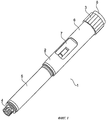
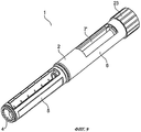
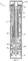
На фиг.1 представлено перспективное изображение инъекционного устройства согласно первому варианту изобретения.1 is a perspective view of an injection device according to a first embodiment of the invention.
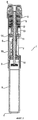
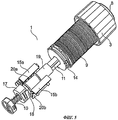
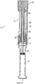
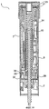
На фиг.2 инъекционное устройство по фиг.1 показано в продольном разрезе.In Fig.2, the injection device of Fig.1 is shown in longitudinal section.
На фиг.3-6 представлены частичные виды инъекционного устройства по фиг.1 и 2 на различных этапах проведения инъекции.Figure 3-6 shows partial views of the injection device of figures 1 and 2 at various stages of the injection.
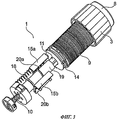
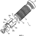
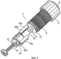
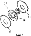
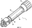
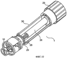
На фиг.7 показано, с пространственным разделением частей, электронное детекторное средство для использования в инъекционном устройстве по фиг.1-6.In Fig.7 shows, with a spatial separation of the parts, the electronic detector means for use in the injection device of Fig.1-6.
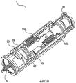
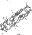
На фиг.8 показано, с пространственным разделением частей, инъекционное устройство по фиг.1-6.In Fig.8 shows, with a spatial separation of the parts, the injection device of Fig.1-6.
На фиг.9 представлено перспективное изображение инъекционного устройства согласно второму варианту изобретения.Fig. 9 is a perspective view of an injection device according to a second embodiment of the invention.
На фиг.10 инъекционное устройство по фиг.9 показано в продольном разрезе.10, the injection device of FIG. 9 is shown in longitudinal section.
На фиг.11-14 представлены частичные виды инъекционного устройства по фиг.9 и 10 на различных этапах проведения инъекции.11-14 are partial views of the injection device of Figures 9 and 10 at various stages of the injection.
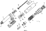
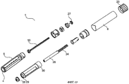
На фиг.15, с пространственным разделением частей, показано инъекционное устройство по фиг.9-14.On Fig, with a spatial separation of the parts, shows the injection device of Fig.9-14.
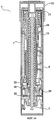
На фиг.16-18 в продольных разрезах показано инъекционное устройство согласно третьему варианту изобретения на различных этапах проведения инъекции.On Fig-18 in longitudinal sections shows an injection device according to the third variant of the invention at various stages of the injection.
На фиг.19-21 представлены частичные виды инъекционного устройства по фиг.16-18 для тех же этапов проведения инъекции.On Fig-21 presents partial views of the injection device of Fig-18 for the same stages of the injection.
Осуществление изобретенияThe implementation of the invention
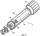
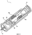
На фиг.1 представлено перспективное изображение инъекционного устройства согласно первому варианту изобретения. Инъекционное устройство 1 содержит корпус 2, дозирующую головку 3, находящуюся на проксимальном конце инъекционного устройства 1, и часть 4, рассчитанную на прием инъекционной иглы, устанавливаемой на дистальном конце инъекционного устройства 1. В корпусе 2 имеются секция 5 для установки картриджа и секция 6, содержащая табло 7 для отображения объемов установленной дозы и/или инъецированной дозы. Смежно с дозирующей головкой 3 расположена инъекционная (спусковая) кнопка 8. Когда требуется произвести инъекцию, дозирующую головку 3 вращают, чтобы задать желательную дозу. Затем, когда инъекционная игла будет установлена в зоне инъекции, нажимают на спусковую кнопку 8, обеспечивая тем самым инъекцию установленной дозы. Эта операция будет подробнее описана далее.1 is a perspective view of an injection device according to a first embodiment of the invention. The
На фиг.2 инъекционное устройство по фиг.1 показано в продольном разрезе. Оно содержит торсионную пружину 9, расположенную вокруг снабженного резьбой штока 10 поршня коаксиально с ним. Когда дозирующую головку 3 вращают в процессе установки дозы, торсионная пружина 9 закручивается и в ней запасается энергия. Данный эффект реализуется следующим образом. Дозирующая головка 3 во время установки дозы сопрягается, с возможностью вращения, с защелкой 11. Защелка 11 связана также с торсионной пружиной 9. Таким образом, вращение дозирующей головки 3 заставляет вращаться защелку 11, обеспечивая закручивание торсионной пружины 9. Кроме того, вращение дозирующей головки 3, благодаря наличию резьбового сопряжения 13, заставляет гайку 12 двигаться в направлении дозирующей головки 3. Действие гайки 12 аналогично действию шкального барабана в инъекционном устройстве с механическим детектированием объема установленной дозы, т.е. осевое и угловое положения гайки 12 определяют объем установленной дозы. Однако, в отличие от обычного барабана, гайка 12 согласно данному варианту изобретения не должна отображать установленную дозу. Как следствие, нет необходимости помещать гайку 12 в такое положение, чтобы ее можно было легко видеть. Соответственно, как показано на фиг.2, гайка 12 находится во внутренней зоне инъекционного устройства 1.In Fig.2, the injection device of Fig.1 is shown in longitudinal section. It contains a
Инъекционное устройство 1 дополнительно снабжено комплектом дисковидных элементов 14, установленных с возможностью взаимного вращения во время установки дозы, а также во время осуществления инъекции. На каждый дисковидный элемент 14 нанесен слой металла, образующий определенный паттерн. В результате дисковидные элементы 14 образуют конденсатор, емкость которого изменяется в зависимости от углового положения, т.е. от взаимного углового смещения дисковидных элементов 14. Таким образом, эта емкость является мерой взаимного углового смещения дисковидных элементов 14 и, как следствие, мерой установленной или инъецированной дозы (как это будет подробно описано далее).The
Электронный контур (не изображен) выполнен с возможностью считывания емкости дисковидных элементов 14 и передачи соответствующего размера дозы на табло 7, так что пользователь может видеть релевантный размер дозы.An electronic circuit (not shown) is configured to read the capacitance of the disk-shaped
Имеются также линейные датчики для отслеживания осевых перемещений определенных частей инъекционного устройства. Линейные датчики могут представлять собой датчики с емкостной связью, описанные в патенте США №5731707. Во время установки дозы дисковидные элементы 14 характеризуют угловое положение дозирующей головки 3, тогда как осевое положение одного или более линейных датчиков характеризует количество полных оборотов, которые совершила дозирующая головка 3. Таким образом, для электронного детектирования установленной дозы (т.е. для определения ее абсолютного значения) совместно используются угловое положение дисковидных элементов 14 и осевое положение линейного датчика (линейных датчиков). Аналогичное решение может быть использовано и для получения абсолютного значения инъецированной дозы.Linear sensors are also available to track axial movements of certain parts of the injection device. Linear sensors may be capacitively coupled sensors described in US Pat. No. 5,731,707. During dose setting, the disk-shaped
Когда требуется инъецировать установленную дозу, производят нажатие на спусковую кнопку 8, отсоединяя тем самым защелку 11 от корпуса 2. В результате защелка 11 может вращаться, так что энергия, запасенная в торсионной пружине 9 при установке дозы, заставляет защелку 11 повернуться в свое начальное положение. Защелка 11 через храповой элемент 17 (показанный на фиг.5, 6 и 8) связана со штоком 10 поршня, поэтому шток 10 поршня при вращении защелки также будет вращаться. Поскольку шток 10 поршня связан с корпусом 2 посредством резьбы, это вращение заставит шток 10 поршня двигаться в сторону секции 5 для установки картриджа, имеющейся в корпусе 2. Как следствие, посредством инъекционного устройства 1 будет инъецировано количество медикамента, соответствующее установленной перед этим дозе.When you want to inject the set dose, press the
Во время осуществления инъекции дисковидные элементы 14 совершают вращательное движение относительно друг друга, а печатная плата 15 считывает соответствующую емкость и обеспечивает выведение соответствующей инъецированной дозы на табло 7 подобно тому, как это было описано выше применительно к установке дозы.During the injection, the disk-shaped
На фиг.3-6 представлены частичные виды инъекционного устройства по фиг.1 и 2 на различных этапах проведения инъекции. Для большей ясности части инъекционного устройства 1, не участвующие в осуществлении инъекции, не изображены.Figure 3-6 shows partial views of the injection device of figures 1 and 2 at various stages of the injection. For clarity, parts of the
На фиг.3 инъекционное устройство 1 показано в исходном положении, когда оно готово к установке дозы. Чтобы установить дозу, дозирующую головку 3 вращают, создавая тем самым натяг в торсионной пружине 9 и обеспечивая взаимное вращение дисковидных элементов 14, описанное выше. При этом печатная плата 15а перемещается в дистальном направлении, т.е. от дозирующей головки 3, поскольку направляющий выступ 18 на продолжении 19 защелки взаимодействует с направляющим пазом 20а, выполненным в печатной плате 15а.In Fig. 3, the
На фиг.4 инъекционное устройство 1 по фиг.1-3 показано в положении, когда доза уже установлена, так что устройство 1 готово для проведения инъекции. При сравнении фиг.3 и фиг.4 видно, что печатная плата 15а переместилась в дистальном направлении. Для ясности дозирующая головка не показана. Чтобы инициировать инъекцию, нажимают на спусковую кнопку 8. При этом защелка 11 отсоединяется от корпуса, так что энергия, запасенная в торсионной пружине 9, высвобождается. Высвобожденная энергия заставляет защелку 11, вращаясь, вернуться обратно. В результате шток 10 поршня движется в дистальном направлении, как это было описано выше.In FIG. 4, the
На фиг.5 инъекционное устройство 1 по фиг.1-4 показано во время осуществления инъекции. Из фиг.5 понятно, что под действием спусковой кнопки 8 продолжение 19 защелки переместилось в дистальном направлении.5, the
На фиг.6 инъекционное устройство 1 по фиг.1-5 показано в положении, соответствующем завершению инъекции. Соответственно, печатная плата 15а вернулась в положение, показанное на фиг.3. При сравнении фиг.3 и 6 видно, что на фиг.6 спусковая кнопка 8 все еще нажата, т.е. инъекция только что завершена, а инъекционное устройство 1 еще не готово для установки новой дозы. Видно также, что шток 10 поршня переместился в дистальном направлении. Это означает, что инъекция была произведена в результате взаимодействия между штоком 10 поршня и поршнем, находящимся внутри картриджа, содержащего инъецируемый медикамент.6, the
На фиг.7 показано, с пространственным разделением частей, электронное детекторное средство (в форме комплекта дисковидных элементов 14) для использования в инъекционном устройстве по фиг.1-6. Электронное детекторное средство содержит два наружных диска 21 и расположенный между ними третий диск 22. На третьем диске 22 сформирован металлический паттерн, который изменяется в зависимости от углового положения на третьем диске. Наружные диски 21 и третий диск 22 способны вращаться относительно друг друга. Как следствие, конденсатор, образованный третьим диском 22 и, по меньшей мере, одним из наружных дисков 21, имеет емкость, которая изменяется в зависимости от взаимного углового смещения наружных дисков 21 и третьего диска 22.7 shows, with a spatial separation of the parts, an electronic detector means (in the form of a set of disk-shaped elements 14) for use in the injection device of FIGS. 1-6. The electronic detection means comprises two
В соответствии с первым вариантом изобретения устройство выполнено таким образом, что нулевое положение в повторяющейся траектории подвижных частей всегда соответствует одному и тому же угловому положению. Это позволяет получить абсолютный (а не относительный) электронный отсчет и тем самым обеспечить высокую надежность работы.According to a first embodiment of the invention, the device is designed in such a way that the zero position in the repeating path of the moving parts always corresponds to the same angular position. This allows you to get an absolute (and not relative) electronic readout and thereby ensure high reliability.
На фиг.8 инъекционное устройство по фиг.1-6 показано с пространственным разделением частей, благодаря чему хорошо видны индивидуальные детали этого устройства.In Fig. 8, the injection device in Figs. 1-6 is shown with a spatial separation of the parts, so that the individual details of this device are clearly visible.
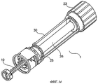
На фиг.9 представлено перспективное изображение инъекционного устройства согласно второму варианту изобретения. Инъекционное устройство 1 содержит корпус 2 с секцией 5 для установки картриджа и с секцией 6, содержащей табло (не изображено), расположенное на участке 7′. На дистальном конце инъекционного устройства 1 имеется часть 4 для приема инъекционной иглы. Инъекционное устройство 1 снабжено также дозирующей головкой, скомбинированной со спусковой кнопкой. При установке дозы такую комбинированную спусковую кнопку 23 нужно вращать, а чтобы произвести инъекцию этой дозы, на кнопку 23 нужно нажать.Fig. 9 is a perspective view of an injection device according to a second embodiment of the invention. The
На фиг.10 инъекционное устройство по фиг.9 показано в продольном разрезе. В данном варианте оно содержит пружину 24 сжатия, расположенную вокруг резьбового штока 10 поршня соосно с ним. Эта пружина 24 расположена, по существу, по всей длине секции 6 корпуса 2, несущей табло 7.10, the injection device of FIG. 9 is shown in longitudinal section. In this embodiment, it comprises a
Инъекционное устройство 1 содержит также компонент 25 для сжатия пружины, перемещающийся в процессе установки дозы в проксимальном направлении и за счет этого сжимающий пружину 24, т.е. обеспечивающий запасание в ней энергии.The
Когда требуется установить дозу, приводят во вращение комбинированную спусковую кнопку 23. В результате приходит во вращение дозирующий стержень 26. Он связан с компонентом 25 для сжатия пружины таким образом, что одновременно с комбинированной спусковой кнопкой 23 вращается и этот компонент 25. Компонент 25 для сжатия пружины связан также (посредством резьбы) со штоком 10 поршня, вращению которого препятствует первый блокирующий элемент 27. Осевому перемещению данного штока препятствует второй блокирующий элемент 28, который также связан со штоком 10 поршня посредством резьбы. Соответственно, вращение компонента 25 для сжатия пружины приводит к его перемещению по резьбе штока 10 поршня в проксимальном направлении, что вызывает сжатие пружины 24.When a dose is to be set, the combined
Когда требуется произвести инъекцию установленной дозы, производят нажатие на комбинированную спусковую кнопку 23 в осевом (дистальном) направлении. При этом приходит в движение удлиненный элемент 30, освобождая тем самым второй блокирующий элемент 28 для вращения, которое будет описано далее. В результате у штока 10 поршня появляется возможность осевого перемещения. При этом пружина 24 будет смещать компонент 25 для сжатия пружины в дистальном направлении, а резьбовое сопряжение между данным компонентом 25 и штоком 10 поршня заставит шток 10 поршня также двигаться в дистальном направлении, обеспечивая инъекцию установленной дозы. По завершении инъекции установленной дозы компонент 25 для сжатия пружины упрется во второй блокирующий элемент 28, который, таким образом, выполнит функцию упора (опорного компонента), предотвращающего инъекцию дозы, превышающей объем установленной дозы.When it is required to inject the prescribed dose, press the combined
Инъекционное устройство в представленном варианте снабжено трещоточным механизмом, обеспечивающим звуковые и/или тактильные щелчки при вращении комбинированной спусковой кнопки 23, причем каждый щелчок соответствует заданному приращению устанавливаемой дозы. Данный трещоточный механизм предпочтительно обеспечивает также позиционирование комбинированной спусковой кнопки 23 дискретными шагами, например при 24, 36 или 48 шагах за оборот. В представленном варианте трещоточный механизм использует ступенчатую кулачковую поверхность комбинированной спусковой кнопки 23, которая взаимодействует (как это хорошо видно на фиг.11-15) с соответствующей кулачковой поверхностью, зафиксированной от вращения относительно корпуса. Две противолежащие кулачковые поверхности прижимаются одна к другой под действием пружины 24 сжатия. Такое выполнение обеспечивает хорошую дискретность щелчков и предотвращает произвольное срабатывание системы в случае изменения установленной дозы.The injection device in the presented embodiment is equipped with a ratchet mechanism that provides audible and / or tactile clicks when the combined
На фиг.11-14 представлены частичные виды инъекционного устройства по фиг.9 и 10 на различных этапах проведения инъекции. Для большей ясности части инъекционного устройства 1, не участвующие в осуществлении инъекции, не изображены.11-14 are partial views of the injection device of Figures 9 and 10 at various stages of the injection. For clarity, parts of the
На фиг.11 инъекционное устройство 1 показано в исходном положении, когда оно готово к установке дозы. Как описано выше, комбинированную спусковую кнопку 23 вращают, заставляя тем самым дозирующий стержень 26, действующий как компонент для сжатия пружины, перемещаться в проксимальном направлении. Во время установки дозы второй блокирующий элемент 28 находится в зацеплении с зубцами 29, выполненными на удлиненном элементе 30, зафиксированном от вращения относительно корпуса. Тем самым предотвращается вращение второго блокирующего элемента 28 относительно корпуса, так что шток 10 поршня не может перемещаться относительно корпуса в осевом направлении.11, the
На фиг.12 инъекционное устройство 1 показано в положении, когда доза уже установлена, так что устройство 1 готово для проведения инъекции. Из фиг.12 понятно, что дозирующий стержень 26 переместился в проксимальном направлении. Второй блокирующий элемент 28 все еще находится в зацеплении с зубцами 29, так что шток 10 поршня все еще не может перемещаться относительно корпуса в осевом направлении.12, the
Чтобы произвести инъекцию установленной дозы, нужно нажать на комбинированную спусковую кнопку 23, протолкнув тем самым удлиненный элемент 30 в дистальном направлении. В результате зубцы 29 выходят из зацепления со вторым блокирующим элементом 28. Соответственно, второй блокирующий элемент 28 сможет вращаться относительно корпуса, а шток 10 поршня приобретет способность двигаться в осевом направлении относительно корпуса.To inject the set dose, you need to press the combined
На фиг.13 инъекционное устройство 1 показано во время осуществления инъекции установленной дозы. Из фиг.13 понятно, что второй блокирующий элемент 28 и зубцы 29 больше не находятся в зацеплении и что поэтому второй блокирующий элемент 28 способен вращаться относительно корпуса, делая допустимым осевое движение штока 10 поршня. Как следствие, шток 10 поршня способен обеспечить инъекцию установленной для этой цели дозы.13, an
На фиг.14 инъекционное устройство 1 показано в положении, соответствующем завершению инъекции. Сравнивая фиг.11 и фиг.14, можно видеть, что второй блокирующий элемент 28 не находится в зацеплении с зубцами (на фиг.14 не видны) и поэтому инъекционное устройство 1 еще не готово для установки новой дозы. Видно также, что шток 10 поршня переместился в дистальном направлении. Это означает, что инъекция была произведена.On
На фиг.15, с пространственным разделением частей, показано инъекционное устройство по фиг.9-14, благодаря чему хорошо видны индивидуальные детали этого устройства.On Fig, with a spatial separation of the parts, shows the injection device of Fig.9-14, due to which the individual details of this device are clearly visible.
Следует отметить, что данный вариант представлен на фиг.9-15 без электронных детекторных средств. Однако должно быть понятно, что электронные детекторные средства, по существу, идентичные показанным применительно к варианту по фиг.1-8, могут использоваться и в варианте по фиг.9-15.It should be noted that this option is presented in Fig.9-15 without electronic detector means. However, it should be understood that electronic detector means substantially identical to those shown in relation to the embodiment of FIGS. 1-8 can also be used in the embodiment of FIGS. 9-15.
На фиг.16-21 представлены различные виды инъекционного устройства согласно третьему варианту изобретения. В этом варианте данное устройство функционирует, по существу, так же, как инъекционное устройство согласно второму варианту, описанному со ссылками на фиг.9-15. Поэтому подробное описание функционирования инъекционного устройства 1 согласно третьему варианту изобретения не приводится.On Fig-21 presents various types of injection device according to the third variant of the invention. In this embodiment, this device functions essentially the same as the injection device according to the second embodiment described with reference to FIGS. 9-15. Therefore, a detailed description of the operation of the
На фиг.16 инъекционное устройство 1 согласно третьему варианту изобретения представлено в продольном разрезе. Для ясности показана только секция 6 корпуса 2, содержащая табло 7, тогда как часть, несущая картридж, опущена. Инъекционное устройство 1 показано на фиг.16 в положении готовности к установке дозы.In Fig.16
Инъекционное устройство 1 снабжено первым комплектом дисковидных элементов 31, установленных рядом с комбинированной спусковой кнопкой 23. Первый комплект дисковидных элементов 31 функционирует, по существу, аналогично комплекту дисковидных элементов 14, описанному со ссылками на фиг.1-8. В частности, при вращении комбинированной спусковой кнопки 23 в процессе установки дозы дисковидные элементы 31 совершают взаимные вращательные движения, в результате чего изменяется емкость конденсатора, образованного данными элементами. Тем самым обеспечивается возможность электронного детектирования установленной дозы, как это будет описано далее со ссылками на фиг.19-21.The
Инъекционное устройство 1 дополнительно снабжено вторым комплектом дисковидных элементов 32, установленных на дистальном конце секции 6, содержащей табло 7. Второй комплект дисковидных элементов 32 также функционирует, по существу, аналогично дисковидным элементам 14, описанным со ссылками на фиг.1-8. Во время осуществления инъекции установленной дозы шток 10 поршня приводит второй блокирующий элемент 28 во вращение. Это заставляет дисковидные элементы 32 второго комплекта совершать взаимные вращательные движения, изменяя тем самым емкость конденсатора, образованного этими элементами. Тем самым обеспечивается возможность электронного детектирования объема инъецированной дозы, как это будет описано далее со ссылками на фиг.19-21.The
На фиг.17 инъекционное устройство 1 по фиг.16 также показано в продольном разрезе. Однако представленное на фиг.17 положение соответствует завершению установки дозы, в котором компонент 25 для сжатия пружины смещен в проксимальном направлении, так что пружина 24 сжатия находится в сжатом состоянии, т.е. в ней запасена энергия.17, the
На фиг.18 представлено, в продольном разрезе, инъекционное устройство 1 по фиг.16 и 17 после проведения инъекции установленной дозы. Можно видеть, что по сравнению с положением, показанным на фиг.16, шток 10 поршня переместился в дистальном направлении. Инъекция дозы только что завершена. Поэтому комбинированная спусковая кнопка 23 все еще находится в нажатом положении, так что второй блокирующий элемент 28 и удлиненный элемент 30 не находятся во взаимном сопряжении. Как следствие, блокирующий элемент 28 может совершать вращательное движение, что позволяет штоку 10 поршня двигаться в дистальном направлении.On Fig presents, in longitudinal section, the
На фиг.19-21 представлены частичные виды инъекционного устройства 1 на тех же этапах процедуры инъекции, на которых оно показано на фиг.16-18. Для большей ясности части, несущественные для работы инъекционного устройства 1, не изображены.On Fig-21 presents partial views of the
На фиг.19 (как и на фиг.16) инъекционное устройство 1 показано в положении, когда оно готово к установке дозы. На фиг.19 можно видеть печатные платы 15а и 15b. Во время установки дозы печатная плата 15а движется в проксимальном направлении аналогично тому, как это было описано со ссылками на фиг.1-8. Электронное детектирование установленной при этом дозы производится следующим образом. Емкость конденсатора, образованного первым комплектом дисковидных элементов 31, отражает угловое положение комбинированной спусковой кнопки 23, а осевое положение печатной платы 15а - количество полных оборотов, которые совершила эта кнопка. Поэтому для электронного детектирования установленной дозы с получением ее абсолютного значения используется угловое положение первого комплекта дисковидных элементов 31 в сочетании с осевым положением печатной платы 15а.In Fig. 19 (as in Fig. 16), the
Следует отметить, что электронное детектирование установленной дозы в принципе можно было бы осуществить и с использованием только дисковидных элементов 31, т.е. без применения печатной платы 15а. Соответствующий вариант может содержать электронный контур, электронным путем отслеживающий полное количество оборотов, которое комбинированная спусковая кнопка 23 совершает в процессе установки. При этом такое отслеживание производится исключительно на основе сигналов, принимаемых от дисковидных элементов 31. Альтернативно, можно ограничить диапазон поворота компонента, устанавливающего дозу, до 360° или менее, так что любая доза, которую нужно установить, будет задаваться в пределах единственного оборота комбинированной спусковой кнопки 23. В этом случае единичная (минимальная) устанавливаемая доза соответствует повороту комбинированной спусковой кнопки 23 на очень маленький угол, и это потребует выполнить первый комплект дисковидных элементов 31 таким образом, чтобы обеспечить возможность детектирования таких малых изменений в относительном угловом положении этих элементов.It should be noted that the electronic detection of the established dose could, in principle, be carried out using only disk-
На фиг.20 инъекционное устройство 1 показано в положении, когда доза установлена и может быть инъецирована, т.е. фиг.20 соответствует фиг.17. Можно видеть, что по сравнению с положением, показанным на фиг.19, печатная плата 15а переместилась в проксимальном направлении.In Fig. 20, the
Когда требуется осуществить инъекцию установленной дозы, производят нажатие на комбинированную спусковую кнопку (не изображена), так что удлиненный элемент 30 перемещается в дистальном направлении. В результате сформированные на нем зубцы 29 выходят из зацепления с соответствующими им зубцами, выполненными на втором блокирующем элементе 28, при этом второй блокирующий элемент 28 получает возможность вращаться, как это описано выше, заставляя тем самым элементы второго комплекта дисковидных элементов 32 совершать взаимные вращательные перемещения. Кроме того, печатная плата 15b приводится в движение в осевом (дистальном) направлении. Осевое положение этой платы обеспечивает указание на то, в каком режиме (установки дозы или производства инъекции) находится инъекционное устройство.When it is required to inject the prescribed dose, press the combined release button (not shown), so that the
Завершение инъекции установленной дозы заставляет печатную плату 15а переместиться в дистальном направлении, с возвращением к своему исходному положению.The completion of the injection of the prescribed dose causes the printed
На фиг.21 инъекционное устройство 1 показано в положении, когда установленная доза была инъецирована, т.е. фиг.21 соответствует фиг.18. Можно видеть, что печатная плата 15а вернулась в свое исходное положение, а печатная плата 15b переместилась в дистальном направлении. Можно видеть также, что зубцы 29 все еще находятся вне зацепления с зубцами второго блокирующего элемента 28.In FIG. 21, the
Описанные механизмы в описанных вариантах обеспечивают конструкции инъекционного устройства с использованием пружины, эффективные в отношении использования объема. В таких конструкциях имеется пространство для размещения электроники, включая электронное табло, датчики и т.д. В частности, эти конструкции эффективны для инъекционных устройств с электронным табло, жестко зафиксированным относительно корпуса, и с одновременным обеспечением надежной разводки проводов к различным компонентам датчиков. Такие конструкции являются, например, оптимальными для инъекционных устройств с использованием пружины, в которых обеспечивается детектирование положения вращающихся частей во время как установки дозы, так и осуществления операций, связанных с инъекцией.The described mechanisms in the described embodiments provide the design of the injection device using the spring, effective in relation to the use of volume. Such constructions have space for electronics, including electronic displays, sensors, etc. In particular, these designs are effective for injection devices with an electronic board rigidly fixed relative to the housing, while ensuring reliable wiring to the various components of the sensors. Such designs are, for example, optimal for injection devices using springs, in which the position of the rotating parts is detected during both setting the dose and performing operations related to the injection.
Claims (14)
механизм для установки дозы, приводимый в действие для установки желательной дозы, причем функционирование указанного механизма обеспечивает запасание энергии в пружинном компоненте (9, 24),
механизм для осуществления инъекции, содержащий шток (10) поршня, выполненный с возможностью взаимодействия с поршнем, расположенным внутри картриджа, который содержит подлежащий инъецированию медикамент, и обеспечивающим выведение установленной дозы из картриджа через инъекционное устройство (1), причем указанный механизм приводится в действие высвобождением энергии, запасенной в пружинном компоненте (9, 24) во время установки дозы,
средство (14, 15а, 15b, 20a, 20b, 21, 22, 31, 32) электронного детектирования объема установленной дозы и/или средство (14, 15а, 15b, 20a, 20b, 21, 22, 31, 32) электронного детектирования объема инъецированной дозы,
электронное табло (7), отображающее для пользователя установленную дозу и/или инъецированную дозу,
при этом средство электронного детектирования объема установленной дозы и/или средство электронного детектирования объема инъецированной дозы выполнены с возможностью детектирования перемещений подвижного компонента (3, 11, 23, 25, 26, 28), который способен вращаться в двух противоположных направлениях и на который в одном из указанных направлений воздействует упругое усилие.1. An injection device (1) for injecting a dose of a medicament comprising:
a mechanism for setting a dose, actuated to set the desired dose, and the functioning of this mechanism provides energy storage in the spring component (9, 24),
a mechanism for injecting, containing a piston rod (10) configured to interact with a piston located inside the cartridge that contains the medication to be injected and allowing the established dose to be removed from the cartridge through the injection device (1), said mechanism being actuated by release energy stored in the spring component (9, 24) during dose setting,
means (14, 15a, 15b, 20a, 20b, 21, 22, 31, 32) for electronic detection of the set dose volume and / or means (14, 15a, 15b, 20a, 20b, 21, 22, 31, 32) for electronic detection volume of injected dose
an electronic scoreboard (7) showing the set dose and / or the injected dose to the user,
wherein the means for electronically detecting the volume of the set dose and / or the means for electronically detecting the volume of the injected dose are configured to detect movements of the movable component (3, 11, 23, 25, 26, 28), which is capable of rotating in two opposite directions and in which in one from these directions, elastic force acts.
Applications Claiming Priority (2)
| Application Number | Priority Date | Filing Date | Title |
|---|---|---|---|
| EP06020547 | 2006-09-29 | ||
| EP06020547.3 | 2006-09-29 |
Publications (2)
| Publication Number | Publication Date |
|---|---|
| RU2009114321A RU2009114321A (en) | 2010-11-10 |
| RU2453343C2 true RU2453343C2 (en) | 2012-06-20 |
Family
ID=37779398
Family Applications (1)
| Application Number | Title | Priority Date | Filing Date |
|---|---|---|---|
| RU2009114321/14A RU2453343C2 (en) | 2006-09-29 | 2007-09-28 | Injection device with electronic dosimeter |
Country Status (12)
| Country | Link |
|---|---|
| US (2) | US8052655B2 (en) |
| EP (1) | EP2073871B1 (en) |
| JP (1) | JP5113847B2 (en) |
| CN (2) | CN102895718B (en) |
| AU (1) | AU2007301890B2 (en) |
| BR (1) | BRPI0717260A2 (en) |
| CA (1) | CA2663239C (en) |
| DK (1) | DK2073871T3 (en) |
| ES (1) | ES2411732T3 (en) |
| PL (1) | PL2073871T3 (en) |
| RU (1) | RU2453343C2 (en) |
| WO (1) | WO2008037801A1 (en) |
Cited By (2)
| Publication number | Priority date | Publication date | Assignee | Title |
|---|---|---|---|---|
| RU2655084C2 (en) * | 2013-04-10 | 2018-05-23 | Санофи | Injection device |
| RU2678410C2 (en) * | 2013-06-24 | 2019-01-28 | Фарма Консалт Гес.М.Б.Х. | Activator for automatic injector |
Families Citing this family (161)
| Publication number | Priority date | Publication date | Assignee | Title |
|---|---|---|---|---|
| US6663602B2 (en) | 2000-06-16 | 2003-12-16 | Novo Nordisk A/S | Injection device |
| ES2314182T3 (en) | 2002-02-11 | 2009-03-16 | Antares Pharma, Inc. | INTRADERMIC INJECTOR. |
| EP1804865B1 (en) | 2004-10-21 | 2009-09-30 | Novo Nordisk A/S | Dial-down mechanism for wind-up pen |
| EP1850892B2 (en) | 2005-01-24 | 2023-04-19 | Antares Pharma, Inc. | Prefilled needle assisted syringe jet injector |
| US20090043264A1 (en) | 2005-04-24 | 2009-02-12 | Novo Nordisk A/S | Injection Device |
| WO2007131013A1 (en) | 2006-05-03 | 2007-11-15 | Antares Pharma, Inc. | Two-stage reconstituting injector |
| US9144648B2 (en) | 2006-05-03 | 2015-09-29 | Antares Pharma, Inc. | Injector with adjustable dosing |
| ATE458517T1 (en) | 2006-05-16 | 2010-03-15 | Novo Nordisk As | TRANSMISSION MECHANISM FOR AN INJECTION DEVICE |
| JP5253387B2 (en) | 2006-05-18 | 2013-07-31 | ノボ・ノルデイスク・エー/エス | Injection device with mode locking means |
| JP5241714B2 (en) | 2006-07-07 | 2013-07-17 | プロテウス デジタル ヘルス, インコーポレイテッド | Smart parenteral delivery system |
| CN102895718B (en) | 2006-09-29 | 2015-01-14 | 诺沃—诺迪斯克有限公司 | An injection device with electronic detecting means |
| AU2008231897B2 (en) * | 2007-03-23 | 2012-11-29 | Novo Nordisk A/S | An injection device comprising a locking nut |
| EP2190506B1 (en) | 2007-08-17 | 2011-08-17 | Novo Nordisk A/S | Medical device with value sensor |
| US9125979B2 (en) | 2007-10-25 | 2015-09-08 | Proteus Digital Health, Inc. | Fluid transfer port information system |
| DE102007054868A1 (en) * | 2007-11-07 | 2009-05-20 | Arzneimittel Gmbh Apotheker Vetter & Co. Ravensburg | Device and method for mounting a pharmaceutical application aid |
| WO2009067463A1 (en) | 2007-11-19 | 2009-05-28 | Proteus Biomedical, Inc. | Body-associated fluid transport structure evaluation devices |
| US8708957B2 (en) | 2007-12-31 | 2014-04-29 | Novo Nordisk A/S | Electronically monitored injection device |
| WO2009114542A1 (en) | 2008-03-10 | 2009-09-17 | Antares Pharma, Inc. | Injector safety device |
| DK2296732T3 (en) * | 2008-06-11 | 2014-04-07 | Shl Group Ab | DRUG DELIVERY DEVICES |
| EP2318075B1 (en) | 2008-08-05 | 2019-05-22 | Antares Pharma, Inc. | Multiple dosage injector |
| CA2743571C (en) * | 2008-11-17 | 2018-01-02 | Becton, Dickinson And Company | Additive force device for drug delivery pen for intradermal medication injection |
| US8529520B2 (en) | 2009-02-06 | 2013-09-10 | Shl Group Ab | Medicament delivery device with electronic dose sensor |
| EP2408493A1 (en) | 2009-03-20 | 2012-01-25 | Antares Pharma, Inc. | Hazardous agent injection system |
| EP2437808A2 (en) * | 2009-06-03 | 2012-04-11 | Novo Nordisk A/S | Injection device having electronic dosis monitor |
| PL215310B1 (en) * | 2009-10-30 | 2013-11-29 | Kappa Medilab Spolka Z Ograniczona Odpowiedzialnoscia | Automatic applicator, especially for insulin |
| EP2327431A1 (en) | 2009-11-25 | 2011-06-01 | Letcat Aktiebolag | Medical delivery device |
| JP5841951B2 (en) | 2010-02-01 | 2016-01-13 | プロテウス デジタル ヘルス, インコーポレイテッド | Data collection system |
| CN102905612A (en) | 2010-02-01 | 2013-01-30 | 普罗秋斯数字健康公司 | Two-wrist data gathering system |
| CN102946931B (en) * | 2010-04-26 | 2015-09-16 | Shl集团有限责任公司 | Medicament delivery device |
| WO2012046199A1 (en) * | 2010-10-05 | 2012-04-12 | Hendrik Meiring | Liquid dosage monitoring |
| WO2012127046A2 (en) | 2011-03-24 | 2012-09-27 | Sanofi-Aventis Deutschland Gmbh | Device and method for detecting an actuation action performable with a medical device |
| TWI600446B (en) * | 2011-03-25 | 2017-10-01 | 賽諾菲阿凡提斯德意志有限公司 | Dose setting mechanism and injection device |
| JP6175049B2 (en) | 2011-03-30 | 2017-08-02 | ノボ・ノルデイスク・エー/エス | Optimizing system for long-term drug administration plan |
| EP2696918A2 (en) * | 2011-04-11 | 2014-02-19 | Novo Nordisk A/S | Injection device incorporating dose monitoring |
| JP6407715B2 (en) | 2011-05-06 | 2018-10-17 | ノボ・ノルデイスク・エー/エス | A system for optimizing drug dosage regimes over time |
| US20130085349A1 (en) | 2011-06-21 | 2013-04-04 | Yofimeter, Llc | Analyte testing devices |
| WO2013004844A1 (en) | 2011-07-07 | 2013-01-10 | Novo Nordisk A/S | Drug delivery injection pen with add-on dose capturing and display module |
| US9220660B2 (en) | 2011-07-15 | 2015-12-29 | Antares Pharma, Inc. | Liquid-transfer adapter beveled spike |
| US8496619B2 (en) | 2011-07-15 | 2013-07-30 | Antares Pharma, Inc. | Injection device with cammed ram assembly |
| CN103648552B (en) | 2011-07-15 | 2016-08-31 | 赛诺菲-安万特德国有限公司 | drug delivery device with electromechanical drive mechanism |
| EP2732245B1 (en) * | 2011-07-15 | 2019-12-25 | Sanofi-Aventis Deutschland GmbH | A drug delivery device |
| JP2014524297A (en) | 2011-08-18 | 2014-09-22 | ノボ・ノルデイスク・エー/エス | Drug delivery device having means for handling data |
| WO2013037754A2 (en) | 2011-09-13 | 2013-03-21 | Novo Nordisk A/S | Adaptive system for optimizing a drug dosage regimen over time |
| WO2013045506A1 (en) | 2011-09-27 | 2013-04-04 | Novo Nordisk A/S | Medical system configured to collect and transfer data |
| EP2763722B1 (en) | 2011-10-07 | 2016-08-10 | Novo Nordisk A/S | System for determining position of element based on three-axial magnetic sensors |
| MX2014007375A (en) | 2011-12-29 | 2014-08-22 | Novo Nordisk As | Torsion- spring based wind-up autoinjector pen with dial - up/dial - down dosing mechanism. |
| EP2814543B1 (en) * | 2012-02-13 | 2017-10-25 | Sanofi-Aventis Deutschland GmbH | Pen-type drug injection device and electronic add-on monitoring module for monitoring and logging dose setting and administration |
| PT2822618T (en) | 2012-03-06 | 2024-03-04 | Antares Pharma Inc | Prefilled syringe with breakaway force feature |
| JP6457383B2 (en) | 2012-04-06 | 2019-01-23 | アンタレス・ファーマ・インコーポレーテッド | Needle-assisted jet injection of testosterone composition |
| WO2013169804A1 (en) | 2012-05-07 | 2013-11-14 | Antares Pharma, Inc. | Needle assisted jet injection device having reduced trigger force |
| JP6590693B2 (en) * | 2012-08-10 | 2019-10-16 | サノフィ−アベンティス・ドイチュラント・ゲゼルシャフト・ミット・ベシュレンクテル・ハフツング | Pen-type drug injection device and electronic extension monitoring module for monitoring and logging dose setting and administration |
| EP2698179A1 (en) * | 2012-08-14 | 2014-02-19 | Sanofi-Aventis Deutschland GmbH | Injection device |
| WO2014037331A1 (en) * | 2012-09-06 | 2014-03-13 | Sanofi-Aventis Deutschland Gmbh | Pen-type drug injection device and electronic add-on monitoring module for monitoring and logging dose setting and administration |
| GB2508588A (en) * | 2012-11-30 | 2014-06-11 | Owen Mumford Ltd | Medical delivery device comprising mechanical-electrical transducer |
| EP2943236B1 (en) | 2013-01-10 | 2017-05-10 | Novo Nordisk A/S | Medical injection system with dose capturing |
| DK2945668T3 (en) | 2013-01-15 | 2018-09-03 | Sanofi Aventis Deutschland | ASSEMBLY ASSEMBLY FOR A MEDICAL INJECTION DEVICE FOR GENERATION OF USE REPORTS ON THE USE OF THE DIGITAL IMAGE INJECTION DEVICE |
| DK2945673T3 (en) * | 2013-01-15 | 2019-03-25 | Sanofi Aventis Deutschland | decoding |
| ES2763633T3 (en) | 2013-02-11 | 2020-05-29 | Antares Pharma Inc | Needle assisted jet injection device having reduced firing force |
| US9750886B2 (en) * | 2013-02-19 | 2017-09-05 | Novo Nordisk A/S | Drug delivery device with dose capturing module |
| US9833576B2 (en) * | 2013-02-19 | 2017-12-05 | Novo Nordisk A/S | Rotary sensor module with axial switch |
| JP6336490B2 (en) * | 2013-02-19 | 2018-06-06 | ノボ・ノルデイスク・エー/エス | Dose capture cartridge module for drug delivery device |
| CN111442791A (en) * | 2013-03-04 | 2020-07-24 | 德康公司 | Wire seal for detector assembly |
| ES2742046T3 (en) | 2013-03-11 | 2020-02-12 | Antares Pharma Inc | Dose injector with pinion system |
| WO2014165136A1 (en) | 2013-03-12 | 2014-10-09 | Antares Pharma, Inc. | Constant volume prefilled syringes and kits thereof |
| EP2981313B1 (en) * | 2013-04-05 | 2017-06-14 | Novo Nordisk A/S | Drug delivery device and logging module assembly |
| PL2981310T3 (en) | 2013-04-05 | 2017-12-29 | Novo Nordisk A/S | Dose logging device for a drug delivery device |
| JP6348169B2 (en) | 2013-04-05 | 2018-06-27 | ノボ・ノルデイスク・エー/エス | Drug delivery device with integrated magnetic field transfer indicator |
| EP2981312B1 (en) | 2013-04-05 | 2017-12-27 | Novo Nordisk A/S | Logging device adapted to combine doses |
| TW201509470A (en) | 2013-04-10 | 2015-03-16 | 賽諾菲公司 | Injection device |
| US10232118B2 (en) * | 2013-04-10 | 2019-03-19 | Sanofi | Drive assembly for a drug delivery device |
| US9651482B2 (en) | 2013-04-22 | 2017-05-16 | Sanofi-Aventis Deutschland Gmbh | Sensor device with OLED |
| DK2994180T3 (en) * | 2013-05-07 | 2019-12-09 | Sanofi Aventis Deutschland | ADMINISTRATION INSTALLATION FOR AN INJECTION DEVICE |
| EP2999504A1 (en) * | 2013-05-21 | 2016-03-30 | Novo Nordisk A/S | Drug delivery device with piston rod coupling |
| US9956349B2 (en) | 2013-05-21 | 2018-05-01 | Novo Nordisk A/S | Frontloaded drug delivery device with dynamic axial stop feature |
| WO2014191189A1 (en) * | 2013-05-27 | 2014-12-04 | Sanofi-Aventis Deutschland Gmbh | Assembly for a drug delivery device and drug delivery device |
| US11311678B2 (en) | 2013-11-21 | 2022-04-26 | Novo Nordisk A/S | Rotary sensor assembly with space efficient design |
| US11052198B2 (en) | 2013-11-21 | 2021-07-06 | Novo Nordisk A/S | Rotary sensor assembly with axial switch and redundancy feature |
| CN105764549A (en) | 2013-11-21 | 2016-07-13 | 诺和诺德股份有限公司 | Rotary sensor module with resynchronization feature |
| US10512732B2 (en) | 2013-11-22 | 2019-12-24 | Sanofi-Aventis Deutschland Gmbh | Drug delivery device with dose knob clutch |
| EP2881131B1 (en) * | 2013-12-05 | 2019-04-24 | TecPharma Licensing AG | Drive and metering device for an injection device with a pre-tensioned drive spring |
| GB201402826D0 (en) | 2014-02-18 | 2014-04-02 | Owen Mumford Ltd | Injection device |
| EP3125973B1 (en) * | 2014-03-31 | 2018-03-14 | Sanofi-Aventis Deutschland GmbH | Pen-type drug injection device with particular dose scale and dose display window comprising optical filter for unambiguous display of set dose value |
| JP6568112B2 (en) | 2014-06-06 | 2019-08-28 | ノボ・ノルデイスク・エー/エス | Recording device actuated by a drug delivery device |
| WO2015185687A1 (en) | 2014-06-06 | 2015-12-10 | Novo Nordisk A/S | Logging device for drug delivery device |
| WO2016030348A1 (en) | 2014-08-25 | 2016-03-03 | Novo Nordisk A/S | Accessory device with snap feature |
| US10704944B2 (en) | 2014-09-14 | 2020-07-07 | Becton, Dickinson And Company | System and method for capturing dose information |
| US10971260B2 (en) | 2014-09-14 | 2021-04-06 | Becton, Dickinson And Company | System and method for capturing dose information |
| CN106714878B (en) | 2014-10-03 | 2020-04-21 | 诺和诺德股份有限公司 | Pen-shaped drug injector with magnetic dose sensor system and error detection and add-on module |
| EP3209351B1 (en) | 2014-10-23 | 2020-05-06 | Novo Nordisk A/S | Pen-type drug delivery device with electronic display on clip member |
| US10596328B2 (en) | 2014-12-22 | 2020-03-24 | Novo Nordisk A/S | Spring-driven drug delivery device |
| AU2015372441A1 (en) | 2014-12-23 | 2017-08-10 | Automed Pty Ltd | Delivery apparatus, system and associated methods |
| EP3058970A1 (en) | 2015-02-19 | 2016-08-24 | Sanofi-Aventis Deutschland GmbH | Data collection device for attachment to an injection device |
| JP6720203B2 (en) * | 2015-02-27 | 2020-07-08 | ノボ・ノルデイスク・エー/エス | Accessory device with mounting safety features |
| EP3067081A1 (en) | 2015-03-12 | 2016-09-14 | Sanofi | Drug delivery device |
| US10556066B2 (en) | 2015-05-29 | 2020-02-11 | Novo Nordisk A/S | Power efficient electronic device |
| EP4316552A3 (en) | 2015-06-09 | 2024-04-17 | Sanofi-Aventis Deutschland GmbH | Data collection apparatus for attachment to an injection device |
| US11052195B2 (en) | 2015-07-06 | 2021-07-06 | Battelle Memorial Institute | Process and autoinjector device for injections with increased patient comfort |
| US10702658B2 (en) | 2015-07-12 | 2020-07-07 | Patients Pending Ltd. | Cover for liquid delivery system with integrated plunger position sensing, and corresponding method |
| CN107835702B (en) * | 2015-07-13 | 2021-03-09 | 诺和诺德股份有限公司 | Drug delivery device with end-of-dose trigger arrangement |
| EP3374009B1 (en) | 2015-11-11 | 2021-01-06 | Novo Nordisk A/S | Drug delivery device with information capture |
| US11083853B2 (en) | 2015-12-28 | 2021-08-10 | Novo Nordisk A/S | Rotary sensor assembly with low-power feature |
| CN108697855B (en) | 2016-01-06 | 2022-04-22 | 赛诺菲-安万特德国有限公司 | Drug delivery device |
| EP3407940A4 (en) | 2016-01-29 | 2019-09-04 | Companion Medical, Inc. | Automatic medication delivery tracking |
| WO2017148855A1 (en) | 2016-03-01 | 2017-09-08 | Novo Nordisk A/S | Switch arrangement for drug delivery device with data capture |
| US10946144B2 (en) | 2016-03-01 | 2021-03-16 | Novo Nordisk A/S | Power efficient accessory device |
| CA3018732C (en) | 2016-03-25 | 2021-04-20 | Eli Lilly And Company | Determination of a dose set and delivered in a medication delivery device |
| WO2017184401A1 (en) | 2016-04-19 | 2017-10-26 | Eli Lilly And Company | Determination of a dose in a medication delivery device using two moving arrays with teeth and a sensor |
| JP2019514540A (en) | 2016-04-28 | 2019-06-06 | ノボ・ノルデイスク・エー/エス | Accessory device with zero position adjustment feature |
| WO2017186955A1 (en) | 2016-04-29 | 2017-11-02 | Novo Nordisk A/S | Drug delivery system with dose capturing |
| EP3463514B1 (en) | 2016-05-30 | 2024-01-10 | Novo Nordisk A/S | Drug delivery device with zero position adjustment feature |
| WO2017207495A1 (en) | 2016-05-30 | 2017-12-07 | Novo Nordisk A/S | Mounting feature for accessory device |
| US9636464B1 (en) * | 2016-08-01 | 2017-05-02 | Innovative Precision Instruments Limited | Drug delivery device and a drug information detection device |
| AU2017308724B2 (en) * | 2016-08-12 | 2020-04-09 | Eli Lilly And Company | Dose sensing mechanism in a medication delivery device |
| US20190262541A1 (en) | 2016-10-31 | 2019-08-29 | Novo Nordisk A/S | Image capture device with viewing functionality |
| US11318257B2 (en) | 2016-12-01 | 2022-05-03 | Novo Nordisk A/S | Drug delivery device with clutch feature |
| EP3548117B1 (en) | 2016-12-01 | 2021-07-07 | Novo Nordisk A/S | Drug delivery device with torsion spring feature |
| EP3548120B1 (en) | 2016-12-05 | 2022-06-22 | Novo Nordisk A/S | Accessory device with pairing feature |
| US11452819B2 (en) * | 2016-12-15 | 2022-09-27 | Eli Lilly And Company | Medication delivery device with sensing system |
| EP3348298A1 (en) | 2017-01-16 | 2018-07-18 | Novo Nordisk A/S | Drug delivery device with rotationally geared piston rod driver |
| CN110337311B (en) | 2017-02-28 | 2022-01-04 | 伊莱利利公司 | Dose detection and drug identification for drug delivery devices |
| US20200086052A1 (en) | 2017-03-14 | 2020-03-19 | Novo Nordisk A/S | Cap assembly with cartridge |
| EP3595742B1 (en) | 2017-03-15 | 2021-08-25 | Novo Nordisk A/S | Dose capturing assembly with secondary image analysis feature |
| JP2020519353A (en) | 2017-05-09 | 2020-07-02 | ノボ・ノルデイスク・エー/エス | Drug delivery device with audio converter |
| WO2018206439A1 (en) | 2017-05-09 | 2018-11-15 | Novo Nordisk A/S | Flexible electronic label device |
| WO2019001919A1 (en) | 2017-06-27 | 2019-01-03 | Novo Nordisk A/S | Accessory device with pairing feature |
| WO2019046053A1 (en) * | 2017-08-31 | 2019-03-07 | Eli Lilly And Company | Dose detection with piezoelectric sensing for a medication delivery device |
| CN111107894B (en) | 2017-09-22 | 2022-07-12 | 诺和诺德股份有限公司 | Attachment for a drug delivery device |
| JP2020535871A (en) | 2017-09-30 | 2020-12-10 | ノボ・ノルデイスク・エー/エス | Cartridge system for drug delivery devices |
| USD888942S1 (en) * | 2018-04-10 | 2020-06-30 | Janssen Pharmaceuticals, Inc. | Injection device |
| KR102654708B1 (en) | 2017-11-23 | 2024-04-03 | 사노피 | Pharmaceutical injection device with rotary encoder |
| EP3720525A1 (en) | 2017-12-04 | 2020-10-14 | Novo Nordisk A/S | Drug delivery system with multipolar magnet and sensor system |
| US11197964B2 (en) | 2017-12-12 | 2021-12-14 | Bigfoot Biomedical, Inc. | Pen cap for medication injection pen having temperature sensor |
| US11116899B2 (en) | 2017-12-12 | 2021-09-14 | Bigfoot Biomedical, Inc. | User interface for diabetes management systems and devices |
| EP3724888A1 (en) | 2017-12-12 | 2020-10-21 | Bigfoot Biomedical, Inc. | Therapy management systems, methods, and devices |
| US10987464B2 (en) | 2017-12-12 | 2021-04-27 | Bigfoot Biomedical, Inc. | Pen cap for insulin injection pens and associated methods and systems |
| US11083852B2 (en) | 2017-12-12 | 2021-08-10 | Bigfoot Biomedical, Inc. | Insulin injection assistance systems, methods, and devices |
| US11077243B2 (en) | 2017-12-12 | 2021-08-03 | Bigfoot Biomedical, Inc. | Devices, systems, and methods for estimating active medication from injections |
| US11464459B2 (en) | 2017-12-12 | 2022-10-11 | Bigfoot Biomedical, Inc. | User interface for diabetes management systems including flash glucose monitor |
| CN111741785B (en) * | 2018-02-20 | 2023-07-07 | 诺和诺德股份有限公司 | Attachment device with mounting features for engaging a dial member |
| LT3755404T (en) | 2018-02-22 | 2023-10-10 | Eli Lilly And Company | Dose detection system module for medication delivery device |
| JP2021515641A (en) | 2018-03-09 | 2021-06-24 | ノボ・ノルデイスク・エー/エス | Transmission protocol for medical devices with log features |
| US20210042429A1 (en) | 2018-04-03 | 2021-02-11 | Novo Nordisk A/S | Data Transmission Safety Feature |
| US20210220562A1 (en) | 2018-05-18 | 2021-07-22 | Novo Nordisk A/S | Sensor assembly with identifier determination |
| JP7377218B2 (en) | 2018-05-18 | 2023-11-09 | ノボ・ノルデイスク・エー/エス | Drug delivery assembly with information capture |
| US11185636B2 (en) | 2018-07-26 | 2021-11-30 | Verily Life Sciences Llc | Electrostatic rotary encoder |
| WO2020094699A1 (en) | 2018-11-06 | 2020-05-14 | Novo Nordisk A/S | Drug delivery assembly with sensor sampling feature |
| EP3890807A1 (en) | 2018-12-04 | 2021-10-13 | Novo Nordisk A/S | Drug delivery assembly with moving sensor system |
| US11109800B2 (en) | 2019-01-04 | 2021-09-07 | Enable Injections, Inc. | Medical fluid injection apparatus and method with detachable patch and monitoring |
| MX2021008037A (en) | 2019-01-04 | 2021-11-04 | Enable Injections Inc | Medical fluid injection apparatus and method with detachable patch and monitoring. |
| US11948671B2 (en) | 2019-04-11 | 2024-04-02 | Medtronic Minimed, Inc. | Intelligent accessories for medicine dispensing device |
| JP2022531775A (en) * | 2019-05-03 | 2022-07-11 | サノフイ | Rotation sensitive placement for injection devices |
| IL267610A (en) * | 2019-06-24 | 2019-10-31 | Dali Medical Devices Ltd | Dosage monitoring |
| CN114746134A (en) | 2019-12-03 | 2022-07-12 | 诺和诺德股份有限公司 | Dose setting assembly with slack reduction feature |
| CH715791A2 (en) * | 2020-03-26 | 2020-07-31 | Ypsomed Ag | Autoinjector with spill detection, process for its preparation and drive unit for it. |
| US11957542B2 (en) | 2020-04-30 | 2024-04-16 | Automed Patent Holdco, Llc | Sensing complete injection for animal injection device |
| JP2023532586A (en) | 2020-07-08 | 2023-07-28 | ノボ・ノルデイスク・エー/エス | Dose-setting sensor assembly with algorithm auto-calibration |
| JP2023547445A (en) | 2020-10-30 | 2023-11-10 | ノボ・ノルデイスク・エー/エス | Dose logging sensor system with error detection function |
| EP4251243A1 (en) | 2020-11-24 | 2023-10-04 | Novo Nordisk A/S | Fast data transmission feature for medical logging device |
| WO2023169924A1 (en) | 2022-03-10 | 2023-09-14 | Novo Nordisk A/S | Dose logging assembly with rotational transmission feature |
| WO2023208791A1 (en) | 2022-04-25 | 2023-11-02 | Novo Nordisk A/S | Dose logging device with scale drum scanner |
| CN116139369B (en) * | 2023-03-06 | 2023-08-18 | 仲伟营 | Apparatus for detecting a dose of medicament delivered from an injection device |
Citations (4)
| Publication number | Priority date | Publication date | Assignee | Title |
|---|---|---|---|---|
| US5320609A (en) * | 1992-12-07 | 1994-06-14 | Habley Medical Technology Corporation | Automatic pharmaceutical dispensing syringe |
| RU2000100330A (en) * | 1997-06-09 | 2001-10-10 | Ново Нордиск А/С | EXPLOSION DEVICE FOR REGULATED DISPOSAL OF A LIQUID CONTAINER CONTAINED IN THE SPRAYER |
| RU2200588C2 (en) * | 1997-06-17 | 2003-03-20 | Ново Нордиск А/С | Dosing apparatus |
| EP1557189B1 (en) * | 1999-01-14 | 2006-05-17 | Haselmeier Sàrl | Injection device |
Family Cites Families (135)
| Publication number | Priority date | Publication date | Assignee | Title |
|---|---|---|---|---|
| US2326A (en) * | 1841-11-03 | Manner of securing and fastening the rails of bedsteads | ||
| US10204A (en) * | 1853-11-08 | Machine eor turning or cutting- irregular forms | ||
| US158304A (en) * | 1874-12-29 | Improvement in cheese-knives | ||
| US73954A (en) * | 1868-02-04 | Improvement in lifting-jack | ||
| US267207A (en) * | 1882-11-07 | Fruit-basket | ||
| US9133A (en) * | 1852-07-20 | Crupper for harness | ||
| US51368A (en) * | 1865-12-05 | Improvement in car-springs | ||
| US233075A (en) * | 1880-10-12 | Spring-wagon | ||
| US20654A (en) * | 1858-06-22 | Railroad-car seat | ||
| US216663A (en) * | 1879-06-17 | Improvement in drag-saws | ||
| US171983A (en) * | 1876-01-11 | Improvement in clasps | ||
| US230157A (en) * | 1880-07-20 | Of one | ||
| US114800A (en) * | 1871-05-16 | Improvement in joiners clamps | ||
| US24361A (en) * | 1859-06-07 | Jacob j | ||
| NL268186A (en) * | 1960-08-15 | |||
| CH563690A5 (en) * | 1973-03-09 | 1975-06-30 | Radioelectrique Comp Ind | |
| US4634431A (en) * | 1976-11-12 | 1987-01-06 | Whitney Douglass G | Syringe injector |
| WO1980001643A1 (en) | 1979-02-12 | 1980-08-21 | American Hospital Supply Corp | Capacitive switching circuit for energizing remote controlled device |
| JPS56163486A (en) | 1980-05-21 | 1981-12-16 | Citizen Watch Co Ltd | Electronic timepiece |
| US4515584A (en) * | 1982-07-06 | 1985-05-07 | Fujisawa Pharmaceutical Co., Ltd. | Artificial pancreas |
| DE3236374A1 (en) | 1982-10-01 | 1984-04-05 | Brown, Boveri & Cie Ag, 6800 Mannheim | Security paper |
| US4648872A (en) | 1983-11-15 | 1987-03-10 | Kamen Dean L | Volumetric pump with replaceable reservoir assembly |
| ES277095Y (en) | 1984-01-25 | 1985-02-16 | Fernandez-Tresguerres Hernandez Jesus A. | SUPPLIER-DISPENSER OF INJECTABLE PRODUCTS |
| EP0213139A1 (en) | 1984-09-07 | 1987-03-11 | Wagner, Wolfgang, Dr.med. | Injection device with sensor |
| CA1254091A (en) * | 1984-09-28 | 1989-05-16 | Vladimir Feingold | Implantable medication infusion system |
| US4812724A (en) * | 1984-11-13 | 1989-03-14 | Liebel-Flarsheim Corporation | Injector control |
| NL8701091A (en) * | 1987-05-08 | 1988-12-01 | Spruyt Hillen Bv | INJECTION PEN. |
| US4838860A (en) * | 1987-06-26 | 1989-06-13 | Pump Controller Corporation | Infusion pump |
| JPH01100495A (en) | 1987-10-13 | 1989-04-18 | Seiko Epson Corp | Stop watch |
| FR2622457A1 (en) | 1987-11-03 | 1989-05-05 | Piccinali Eric | Mesotherapeutic injector with microprocessor |
| US4898578A (en) * | 1988-01-26 | 1990-02-06 | Baxter International Inc. | Drug infusion system with calculator |
| GB8809115D0 (en) | 1988-04-18 | 1988-05-18 | Turner R C | Syringes |
| JPH02126184A (en) | 1988-11-04 | 1990-05-15 | Casio Comput Co Ltd | Stop watch device |
| JPH02182267A (en) | 1989-01-06 | 1990-07-16 | Oriental Kiden Kk | Drip monitor apparatus |
| DK68789A (en) | 1989-02-14 | 1990-08-15 | Novo Nordisk As | injector |
| GB2229497B (en) | 1989-03-10 | 1992-06-03 | Graseby Medical Ltd | Infusion pump |
| DE3908892A1 (en) | 1989-03-17 | 1990-09-20 | Siemens Ag | CIRCUIT ARRANGEMENT AND DEVICE FOR CONTACTLESS SETPOINT SETTING FOR AN INTEGRATED CIRCUIT COVERED WITH NON-MAGNETIC MATERIAL |
| DE3913001A1 (en) | 1989-04-20 | 1990-10-31 | Herberts Gmbh | HYDROXYL GROUP BINDING AGENT, METHOD FOR THE PRODUCTION THEREOF AND ITS USE |
| DE3923079A1 (en) | 1989-07-13 | 1991-01-24 | Fresenius Ag | Measuring level of electrically conducting liquid - has measuring of infusion liquid or blood from change in capacitance of electrodes in measurement liquid |
| DE3933542A1 (en) | 1989-10-07 | 1991-04-18 | Kg Catts Ges Fuer Erkennungs & | CODE ARRANGEMENT AND DEVICES FOR READING AND CODING THE SAME |
| US5097122A (en) | 1990-04-16 | 1992-03-17 | Pacesetter Infusion, Ltd. | Medication infusion system having optical motion sensor to detect drive mechanism malfunction |
| US5135485A (en) * | 1991-02-25 | 1992-08-04 | Louis Cohen | Capacitance-type fluid level sensor for i.v. and catheter bags |
| US5270685A (en) | 1991-07-02 | 1993-12-14 | Mallinckrodt Medical, Inc. | Syringe pressure monitor |
| US5163904A (en) * | 1991-11-12 | 1992-11-17 | Merit Medical Systems, Inc. | Syringe apparatus with attached pressure gauge |
| US5221268A (en) * | 1991-12-06 | 1993-06-22 | Block Medical, Inc. | Multiple dose control apparatus |
| SG49695A1 (en) * | 1992-10-15 | 1998-06-15 | Gen Hospital Corp | An infusion pump with an electronically loadable drug library |
| US5383865A (en) | 1993-03-15 | 1995-01-24 | Eli Lilly And Company | Medication dispensing device |
| GB9309151D0 (en) * | 1993-05-04 | 1993-06-16 | Zeneca Ltd | Syringes and syringe pumps |
| CA2129284C (en) * | 1993-11-24 | 1999-03-09 | Kenneth J. Niehoff | Controlling plunger drives for fluid injection in animals |
| US5998989A (en) * | 1993-12-22 | 1999-12-07 | Itt Automotive Europe Gmbh | Device including magnet-biased magnetoresistive sensor and rotatable, magnetized encoder for detecting rotary movements |
| AUPM348594A0 (en) * | 1994-01-21 | 1994-02-17 | University Of Melbourne, The | Improvements in syringe pumps |
| US5536249A (en) * | 1994-03-09 | 1996-07-16 | Visionary Medical Products, Inc. | Pen-type injector with a microprocessor and blood characteristic monitor |
| US6110148A (en) * | 1994-07-22 | 2000-08-29 | Health Hero Network, Inc. | Capacitance-based dose measurements in syringes |
| US5720733A (en) | 1994-07-22 | 1998-02-24 | Raya Systems, Inc. | Apparatus for determining and recording injection doses in syringes using electrical capacitance measurements |
| DE19503230A1 (en) | 1995-02-02 | 1996-08-08 | Dietmar Dr Med Enk | Syringe with a damping and pressure measuring device integrated in the piston and method for uniform and pressure-controlled injection by means of this syringe |
| GB2309644B (en) | 1995-05-22 | 2000-05-31 | Wolfgang Wagner | A method and device for diagnosis and injection |
| JP2662858B2 (en) * | 1995-05-24 | 1997-10-15 | 株式会社エナミ精機 | Press machine |
| AU1860697A (en) * | 1995-09-08 | 1997-07-28 | Visionary Medical Products Corporation | Pen-type injector drive mechanism |
| KR100469207B1 (en) * | 1995-10-20 | 2005-03-16 | 화이자 헬스 에이비 | Arrangement in electronically controlled injection devices |
| FR2740345A1 (en) | 1995-10-26 | 1997-04-30 | Neftel Frederic | AUTOMATION DEVICE |
| US5741211A (en) * | 1995-10-26 | 1998-04-21 | Medtronic, Inc. | System and method for continuous monitoring of diabetes-related blood constituents |
| JPH09166474A (en) | 1995-12-19 | 1997-06-24 | Omron Corp | Residual-quantity sensor |
| US5628309A (en) * | 1996-01-25 | 1997-05-13 | Raya Systems, Inc. | Meter for electrically measuring and recording injection syringe doses |
| RU2181299C2 (en) | 1996-02-23 | 2002-04-20 | Ново Нордиск А/С | Syringe with electronic parameter presentation |
| FR2745637B1 (en) * | 1996-03-04 | 1998-05-22 | Motorola Semiconducteurs | SEMICONDUCTOR CHEMICAL SENSOR DEVICE AND THERMOCOUPLE FORMING METHOD THEREFOR |
| JP4187794B2 (en) * | 1996-07-05 | 2008-11-26 | ノボ ノルディスク アクティーゼルスカブ | Dose setting device |
| DE19632402C1 (en) * | 1996-08-02 | 1998-04-09 | Schering Ag | Method of making a prefilled, sterile syringe |
| JPH1117167A (en) | 1997-06-25 | 1999-01-22 | Matsushita Electric Ind Co Ltd | Field-effect transistor and manufacturing method |
| SE9702872D0 (en) | 1997-08-06 | 1997-08-06 | Pharmacia & Upjohn Ab | Automated delivery device and method for its operation |
| US6171276B1 (en) * | 1997-08-06 | 2001-01-09 | Pharmacia & Upjohn Ab | Automated delivery device and method for its operation |
| CH692543A5 (en) | 1997-09-25 | 2002-07-31 | Disetronic Licensing Ag | Dispenser with auto switch. |
| JP3436683B2 (en) * | 1998-03-17 | 2003-08-11 | 株式会社日立ユニシアオートモティブ | Rotation angle detector |
| US6391005B1 (en) * | 1998-03-30 | 2002-05-21 | Agilent Technologies, Inc. | Apparatus and method for penetration with shaft having a sensor for sensing penetration depth |
| JP3017167B2 (en) | 1998-05-20 | 2000-03-06 | インターナショナル・ビジネス・マシーンズ・コーポレイション | Method and apparatus for binarizing a read signal from a data storage medium |
| JP2002518108A (en) | 1998-06-15 | 2002-06-25 | メドラッド インコーポレイテッド | Encoding syringe information |
| US5933671A (en) * | 1998-07-07 | 1999-08-03 | Eastman Kodak Company | Camera with touch sensitive switch |
| US6558320B1 (en) | 2000-01-20 | 2003-05-06 | Medtronic Minimed, Inc. | Handheld personal data assistant (PDA) with a medical device and method of using the same |
| US5993423A (en) * | 1998-08-18 | 1999-11-30 | Choi; Soo Bong | Portable automatic syringe device and injection needle unit thereof |
| AU1794700A (en) | 1998-12-22 | 2000-07-12 | Alcor Medical Instruments Ltd. | Method and device for monitoring fluid level |
| US6277099B1 (en) | 1999-08-06 | 2001-08-21 | Becton, Dickinson And Company | Medication delivery pen |
| ATE375175T1 (en) | 1999-10-12 | 2007-10-15 | Novo Nordisk As | ELECTRONIC AIR INJECTIONS |
| US6585698B1 (en) * | 1999-11-01 | 2003-07-01 | Becton, Dickinson & Company | Electronic medical delivery pen having a multifunction actuator |
| US6673033B1 (en) * | 1999-11-24 | 2004-01-06 | Medrad, Inc. | Injectors, injector systems and injector control |
| US6485465B2 (en) | 2000-03-29 | 2002-11-26 | Medtronic Minimed, Inc. | Methods, apparatuses, and uses for infusion pump fluid pressure and force detection |
| US6663602B2 (en) * | 2000-06-16 | 2003-12-16 | Novo Nordisk A/S | Injection device |
| US6613019B2 (en) | 2000-07-14 | 2003-09-02 | Novo Nordisk A/S | Liquid medication delivery device and a method of delivering an intended dose |
| US6994261B2 (en) | 2000-08-10 | 2006-02-07 | Novo Nirdisk A/S | Support for a cartridge for transferring an electronically readable item of information from the cartridge to an electronic circuit |
| WO2002024257A1 (en) | 2000-09-22 | 2002-03-28 | Novo Nordisk A/S | A medication delivery device |
| EP1404214A2 (en) | 2000-11-24 | 2004-04-07 | CKM Diagnostics, Inc. | Nerve stimulator output control needle with depth determination capability and method of use |
| US6899699B2 (en) | 2001-01-05 | 2005-05-31 | Novo Nordisk A/S | Automatic injection device with reset feature |
| EP2319565A3 (en) | 2001-02-14 | 2013-07-17 | Novo Nordisk A/S | Electronically controlled device |
| US6854620B2 (en) | 2001-04-13 | 2005-02-15 | Nipro Diabetes, Systems, Inc. | Drive system for an infusion pump |
| EP2258425B1 (en) * | 2001-05-16 | 2013-01-30 | Eli Lilly and Company | Medication injector apparatus |
| US7080936B1 (en) * | 2001-06-13 | 2006-07-25 | Simpson Frank B | Wrap spring clutch syringe ram and frit mixer |
| DE10133216B4 (en) * | 2001-07-09 | 2005-01-27 | Tecpharma Licensing Ag | position detection |
| DK200100240U3 (en) | 2001-09-18 | 2001-11-23 | Niels Tessing | garlic Crusher |
| GB0130138D0 (en) | 2001-12-18 | 2002-02-06 | Dca Design Int Ltd | Improvements in an relating to a medicament injection apparatus |
| GB0200637D0 (en) | 2002-01-12 | 2002-02-27 | Dca Design Int Ltd | Improvements in and relating to medicament injection apparatus |
| DE10201875C1 (en) | 2002-01-18 | 2003-05-22 | Austriamicrosystems Ag | Magnetic or electrical field sensor system has modulators with non-inverting and inverting conditions providing for different sensor configurations |
| US7169107B2 (en) | 2002-01-25 | 2007-01-30 | Karen Jersey-Willuhn | Conductivity reconstruction based on inverse finite element measurements in a tissue monitoring system |
| US20040010204A1 (en) | 2002-03-28 | 2004-01-15 | Pearl Technology Holdings, Llc | Electronic/fiberoptic tissue differentiation instrumentation |
| US20050171476A1 (en) | 2002-05-24 | 2005-08-04 | Judson Jared A. | Medication injecting apparatus with fluid container piston-engaging drive member having internal hollow for accommodating drive member shifting mechanism |
| DE10226643A1 (en) * | 2002-06-14 | 2004-01-15 | Disetronic Licensing Ag | Piston stopper for injection device, product container and injection device |
| US6929619B2 (en) | 2002-08-02 | 2005-08-16 | Liebel-Flarshiem Company | Injector |
| US20040051368A1 (en) | 2002-09-17 | 2004-03-18 | Jimmy Caputo | Systems and methods for programming pumps |
| EP1542744B1 (en) | 2002-09-24 | 2009-06-24 | SHL Group AB | Injecting device |
| AU2003266644B2 (en) | 2002-09-26 | 2008-04-03 | Men-Dar Wu | Therapeutic causing contraction of mucosal tissue, method of treating diseases relating to mucosal tissues, injector and therapeutic set |
| CH695926A5 (en) * | 2002-11-25 | 2006-10-31 | Tecpharma Licensing Ag | Device for automatically injecting an active ingredient. |
| US8016798B2 (en) | 2003-02-24 | 2011-09-13 | Integrated Sensing Systems, Inc. | Fluid delivery system and sensing unit therefor |
| GB0304823D0 (en) | 2003-03-03 | 2003-04-09 | Dca Internat Ltd | Improvements in and relating to a pen-type injector |
| RU2004132832A (en) | 2003-03-06 | 2005-08-27 | Лайфскен, Инк. (Us) | SYSTEM AND METHOD FOR PUNCTING DERMAL TISSUE |
| EP1608305B1 (en) | 2003-03-24 | 2008-07-30 | Novo Nordisk A/S | Transparent electronic marking of a medicament container |
| MXPA05011377A (en) | 2003-04-23 | 2006-01-30 | Vasogen Ireland Ltd | Dispensing systems. |
| US7641668B2 (en) | 2003-05-16 | 2010-01-05 | Scimed Life Systems, Inc. | Fluid delivery system and related methods of use |
| WO2005018721A1 (en) * | 2003-08-12 | 2005-03-03 | Eli Lilly And Company | Medication dispensing apparatus with triple screw threads for mechanical advantage |
| CN103143079B (en) | 2004-03-03 | 2016-09-28 | 株式会社根本杏林堂 | Chemical liquid infusion system |
| GB0406088D0 (en) | 2004-03-18 | 2004-04-21 | Smiths Group Plc | Infusion apparatus and methods |
| WO2006006643A1 (en) | 2004-07-14 | 2006-01-19 | Nemoto Kyorindo Co., Ltd. | Medical liquid injection system |
| DE102004046003A1 (en) | 2004-09-17 | 2006-03-30 | Arzneimittel Gmbh Apotheker Vetter & Co. Ravensburg | Pharmaceutical package, as a syringe or vial or capsule, has an integrated microchip and antenna to give a unique and tamper-proof identity |
| CN101039713B (en) | 2004-10-14 | 2011-10-12 | 诺和诺德公司 | Syringe with dosis mechanism |
| ATE452671T1 (en) * | 2004-10-21 | 2010-01-15 | Novo Nordisk As | INJECTION DEVICE HAVING A PROCESSOR FOR COLLECTING EXHAUST INFORMATION |
| CN101084028B (en) * | 2004-10-21 | 2010-06-09 | 诺和诺德公司 | Injection device with torsion spring and rotatable display |
| ATE445429T1 (en) | 2004-10-21 | 2009-10-15 | Novo Nordisk As | INJECTION DEVICE WITH INTERNAL DOSE INDICATOR |
| ITVR20040168A1 (en) | 2004-10-25 | 2005-01-25 | C M Tecnologie S R L | SELECTOR, PARTICULARLY BUT NOT ONLY FOR AUTOMATIC DRINK DISTRIBUTORS |
| DE102004063644A1 (en) | 2004-12-31 | 2006-07-20 | Tecpharma Licensing Ag | Device for the dosed administration of a fluid product with torsion spring drive |
| ES2633917T3 (en) * | 2005-01-21 | 2017-09-26 | Novo Nordisk A/S | Automatic injection device with a superior release mechanism |
| JP2006250582A (en) | 2005-03-08 | 2006-09-21 | Hitachi Plant Technologies Ltd | Rfid tag with load sensor |
| WO2006116997A1 (en) | 2005-04-29 | 2006-11-09 | Novo Nordisk A/S | Handheld injection device with integrated force sensor |
| DK200500116U3 (en) | 2005-05-23 | 2005-06-24 | Novo Nordisk As | Motor-powered injection apparatus |
| US20060276753A1 (en) | 2005-06-01 | 2006-12-07 | Victor Kronestedt | Device for delivering medicament |
| DE102005060929A1 (en) | 2005-09-14 | 2007-03-15 | Tecpharma Licensing Ag | Product e.g. insulin, injecting device, has housing and operating knob with locking units that are formed such that movement of operating knob in one direction has smaller resistance in contrast to movement in other direction |
| EP1948112A4 (en) | 2005-10-11 | 2011-04-13 | Podaima Blake | Smart medical compliance method and system |
| JP5253387B2 (en) | 2006-05-18 | 2013-07-31 | ノボ・ノルデイスク・エー/エス | Injection device with mode locking means |
| CN102895718B (en) * | 2006-09-29 | 2015-01-14 | 诺沃—诺迪斯克有限公司 | An injection device with electronic detecting means |
| US20080306443A1 (en) | 2007-06-06 | 2008-12-11 | Mallinckrodt Inc. | Medical Fluid Injector Having Wireless Pressure Monitoring Feature |
-
2007
- 2007-09-28 CN CN201210368462.XA patent/CN102895718B/en active Active
- 2007-09-28 BR BRPI0717260-5A patent/BRPI0717260A2/en not_active IP Right Cessation
- 2007-09-28 JP JP2009529715A patent/JP5113847B2/en active Active
- 2007-09-28 WO PCT/EP2007/060331 patent/WO2008037801A1/en active Application Filing
- 2007-09-28 ES ES07820718T patent/ES2411732T3/en active Active
- 2007-09-28 US US12/442,168 patent/US8052655B2/en active Active
- 2007-09-28 RU RU2009114321/14A patent/RU2453343C2/en not_active IP Right Cessation
- 2007-09-28 AU AU2007301890A patent/AU2007301890B2/en not_active Ceased
- 2007-09-28 DK DK07820718.0T patent/DK2073871T3/en active
- 2007-09-28 PL PL07820718T patent/PL2073871T3/en unknown
- 2007-09-28 CA CA2663239A patent/CA2663239C/en not_active Expired - Fee Related
- 2007-09-28 EP EP07820718A patent/EP2073871B1/en active Active
- 2007-09-28 CN CN2007800360715A patent/CN101516421B/en active Active
-
2011
- 2011-09-26 US US13/245,381 patent/US8632509B2/en active Active
Patent Citations (5)
| Publication number | Priority date | Publication date | Assignee | Title |
|---|---|---|---|---|
| US5320609A (en) * | 1992-12-07 | 1994-06-14 | Habley Medical Technology Corporation | Automatic pharmaceutical dispensing syringe |
| RU2000100330A (en) * | 1997-06-09 | 2001-10-10 | Ново Нордиск А/С | EXPLOSION DEVICE FOR REGULATED DISPOSAL OF A LIQUID CONTAINER CONTAINED IN THE SPRAYER |
| RU2200588C2 (en) * | 1997-06-17 | 2003-03-20 | Ново Нордиск А/С | Dosing apparatus |
| EP1557189B1 (en) * | 1999-01-14 | 2006-05-17 | Haselmeier Sàrl | Injection device |
| RU2003101065A (en) * | 2000-06-16 | 2004-07-27 | Ново Нордиск А/С | INJECTION DEVICE WITH REDUCER |
Cited By (2)
| Publication number | Priority date | Publication date | Assignee | Title |
|---|---|---|---|---|
| RU2655084C2 (en) * | 2013-04-10 | 2018-05-23 | Санофи | Injection device |
| RU2678410C2 (en) * | 2013-06-24 | 2019-01-28 | Фарма Консалт Гес.М.Б.Х. | Activator for automatic injector |
Also Published As
| Publication number | Publication date |
|---|---|
| US8632509B2 (en) | 2014-01-21 |
| JP2010504779A (en) | 2010-02-18 |
| CN101516421B (en) | 2012-11-28 |
| CA2663239C (en) | 2015-03-31 |
| EP2073871B1 (en) | 2013-03-20 |
| CN101516421A (en) | 2009-08-26 |
| JP5113847B2 (en) | 2013-01-09 |
| CA2663239A1 (en) | 2008-04-03 |
| RU2009114321A (en) | 2010-11-10 |
| DK2073871T3 (en) | 2013-06-10 |
| BRPI0717260A2 (en) | 2013-10-15 |
| WO2008037801A1 (en) | 2008-04-03 |
| EP2073871A1 (en) | 2009-07-01 |
| PL2073871T3 (en) | 2013-08-30 |
| ES2411732T3 (en) | 2013-07-08 |
| US8052655B2 (en) | 2011-11-08 |
| CN102895718A (en) | 2013-01-30 |
| AU2007301890B2 (en) | 2012-08-16 |
| AU2007301890A1 (en) | 2008-04-03 |
| US20090318865A1 (en) | 2009-12-24 |
| US20120078194A1 (en) | 2012-03-29 |
| CN102895718B (en) | 2015-01-14 |
Similar Documents
| Publication | Publication Date | Title |
|---|---|---|
| RU2453343C2 (en) | Injection device with electronic dosimeter | |
| CA2314940C (en) | Improved medication delivery pen | |
| JP6423362B2 (en) | Medical injection system with dose collection function | |
| US20190269858A1 (en) | Multi-channel rotary encoder | |
| US20130123685A1 (en) | Electronically monitored injection device | |
| US20080154211A1 (en) | Dose Setting Mechanism for an Injection Device Capable of Presetting a Maximum Dose | |
| JP6321680B2 (en) | Pen-type drug injection device with friction-reducing dose encoder mechanism | |
| JP2018519949A (en) | Drug delivery device with end-of-dose trigger arrangement | |
| US20210228810A1 (en) | Dosage tracking apparatus, dosage tracking system, and related methods of use | |
| US20220040415A1 (en) | Medication delivery device with gear set dosage system | |
| JP7145860B2 (en) | A drive arrangement with a rotatable geared drive rod | |
| CN110893253A (en) | Universal connection device for pen injectors | |
| CA3111681A1 (en) | Injection device | |
| US20230293821A1 (en) | Dose setting sensor assembly with algorithmic auto calibration | |
| US20220409810A1 (en) | Device For Inserting A Needle | |
| JP2023504654A (en) | Dose setting assembly having features to reduce slack |
Legal Events
| Date | Code | Title | Description |
|---|---|---|---|
| MM4A | The patent is invalid due to non-payment of fees |
Effective date: 20160929 |