EP2881131B1 - Drive and metering device for an injection device with a pre-tensioned drive spring - Google Patents
Drive and metering device for an injection device with a pre-tensioned drive spring Download PDFInfo
- Publication number
- EP2881131B1 EP2881131B1 EP13195948.8A EP13195948A EP2881131B1 EP 2881131 B1 EP2881131 B1 EP 2881131B1 EP 13195948 A EP13195948 A EP 13195948A EP 2881131 B1 EP2881131 B1 EP 2881131B1
- Authority
- EP
- European Patent Office
- Prior art keywords
- dose
- drive
- housing
- product
- selection
- Prior art date
- Legal status (The legal status is an assumption and is not a legal conclusion. Google has not performed a legal analysis and makes no representation as to the accuracy of the status listed.)
- Active
Links
Images


Classifications
-
- A—HUMAN NECESSITIES
- A61—MEDICAL OR VETERINARY SCIENCE; HYGIENE
- A61M—DEVICES FOR INTRODUCING MEDIA INTO, OR ONTO, THE BODY; DEVICES FOR TRANSDUCING BODY MEDIA OR FOR TAKING MEDIA FROM THE BODY; DEVICES FOR PRODUCING OR ENDING SLEEP OR STUPOR
- A61M5/00—Devices for bringing media into the body in a subcutaneous, intra-vascular or intramuscular way; Accessories therefor, e.g. filling or cleaning devices, arm-rests
- A61M5/178—Syringes
- A61M5/20—Automatic syringes, e.g. with automatically actuated piston rod, with automatic needle injection, filling automatically
-
- A—HUMAN NECESSITIES
- A61—MEDICAL OR VETERINARY SCIENCE; HYGIENE
- A61M—DEVICES FOR INTRODUCING MEDIA INTO, OR ONTO, THE BODY; DEVICES FOR TRANSDUCING BODY MEDIA OR FOR TAKING MEDIA FROM THE BODY; DEVICES FOR PRODUCING OR ENDING SLEEP OR STUPOR
- A61M5/00—Devices for bringing media into the body in a subcutaneous, intra-vascular or intramuscular way; Accessories therefor, e.g. filling or cleaning devices, arm-rests
- A61M5/178—Syringes
- A61M5/31—Details
- A61M5/315—Pistons; Piston-rods; Guiding, blocking or restricting the movement of the rod or piston; Appliances on the rod for facilitating dosing ; Dosing mechanisms
- A61M5/31565—Administration mechanisms, i.e. constructional features, modes of administering a dose
- A61M5/31576—Constructional features or modes of drive mechanisms for piston rods
- A61M5/31583—Constructional features or modes of drive mechanisms for piston rods based on rotational translation, i.e. movement of piston rod is caused by relative rotation between the user activated actuator and the piston rod
- A61M5/31585—Constructional features or modes of drive mechanisms for piston rods based on rotational translation, i.e. movement of piston rod is caused by relative rotation between the user activated actuator and the piston rod performed by axially moving actuator, e.g. an injection button
-
- A—HUMAN NECESSITIES
- A61—MEDICAL OR VETERINARY SCIENCE; HYGIENE
- A61M—DEVICES FOR INTRODUCING MEDIA INTO, OR ONTO, THE BODY; DEVICES FOR TRANSDUCING BODY MEDIA OR FOR TAKING MEDIA FROM THE BODY; DEVICES FOR PRODUCING OR ENDING SLEEP OR STUPOR
- A61M5/00—Devices for bringing media into the body in a subcutaneous, intra-vascular or intramuscular way; Accessories therefor, e.g. filling or cleaning devices, arm-rests
- A61M5/178—Syringes
- A61M5/31—Details
- A61M5/315—Pistons; Piston-rods; Guiding, blocking or restricting the movement of the rod or piston; Appliances on the rod for facilitating dosing ; Dosing mechanisms
- A61M5/31533—Dosing mechanisms, i.e. setting a dose
- A61M5/31545—Setting modes for dosing
- A61M5/31548—Mechanically operated dose setting member
- A61M5/3155—Mechanically operated dose setting member by rotational movement of dose setting member, e.g. during setting or filling of a syringe
- A61M5/31553—Mechanically operated dose setting member by rotational movement of dose setting member, e.g. during setting or filling of a syringe without axial movement of dose setting member
-
- A—HUMAN NECESSITIES
- A61—MEDICAL OR VETERINARY SCIENCE; HYGIENE
- A61M—DEVICES FOR INTRODUCING MEDIA INTO, OR ONTO, THE BODY; DEVICES FOR TRANSDUCING BODY MEDIA OR FOR TAKING MEDIA FROM THE BODY; DEVICES FOR PRODUCING OR ENDING SLEEP OR STUPOR
- A61M5/00—Devices for bringing media into the body in a subcutaneous, intra-vascular or intramuscular way; Accessories therefor, e.g. filling or cleaning devices, arm-rests
- A61M5/178—Syringes
- A61M5/31—Details
- A61M5/315—Pistons; Piston-rods; Guiding, blocking or restricting the movement of the rod or piston; Appliances on the rod for facilitating dosing ; Dosing mechanisms
- A61M5/31565—Administration mechanisms, i.e. constructional features, modes of administering a dose
- A61M5/31576—Constructional features or modes of drive mechanisms for piston rods
- A61M5/31583—Constructional features or modes of drive mechanisms for piston rods based on rotational translation, i.e. movement of piston rod is caused by relative rotation between the user activated actuator and the piston rod
-
- A—HUMAN NECESSITIES
- A61—MEDICAL OR VETERINARY SCIENCE; HYGIENE
- A61M—DEVICES FOR INTRODUCING MEDIA INTO, OR ONTO, THE BODY; DEVICES FOR TRANSDUCING BODY MEDIA OR FOR TAKING MEDIA FROM THE BODY; DEVICES FOR PRODUCING OR ENDING SLEEP OR STUPOR
- A61M5/00—Devices for bringing media into the body in a subcutaneous, intra-vascular or intramuscular way; Accessories therefor, e.g. filling or cleaning devices, arm-rests
- A61M5/178—Syringes
- A61M5/31—Details
- A61M2005/3125—Details specific display means, e.g. to indicate dose setting
- A61M2005/3126—Specific display means related to dosing
Definitions
- the invention relates to a drive and metering device for an injection device for administering or pouring out a liquid product, in particular a medicament, such as insulin for diabetes therapy.
- a drive and metering device for an injection device for administering or pouring out a liquid product, in particular a medicament, such as insulin for diabetes therapy.
- the invention also relates to an injection device having such a drive and metering device.
- the term "medicament” includes any fluid medical formulation suitable for controlled administration by an agent, such as an oral fluid.
- a cannula or hollow needle for example comprising a liquid, a solution, a gel or a fine suspension containing one or more medicinal agents.
- Drug may be a single drug composition or a premixed or co-formulated multi-drug composition from a single container.
- Drug includes drugs such as peptides (eg, insulins, insulin-containing drugs, GLP-1 containing as well as derived or analogous preparations), proteins and hormones, biologically derived or active agents, hormone or gene based drugs, nutritional formulas, enzymes, and other substances both in the art solid (suspended) or liquid form but also polysaccharides, vaccines, DNA or RNA or Oglionukleotide, antibodies or parts of antibodies and suitable base, excipients and carriers.
- drugs such as peptides (eg, insulins, insulin-containing drugs, GLP-1 containing as well as derived or analogous preparations), proteins and hormones, biologically derived or active agents, hormone or gene based drugs, nutritional formulas, enzymes, and other substances both in the art solid (suspended) or liquid form but also polysaccharides, vaccines, DNA or RNA or Oglionukleotide, antibodies or parts of antibodies and suitable base, excipients and carriers.
- drugs such as peptides (
- the drive spring is a clock spring, which is spirally wound from a band-shaped material.
- the spring is tensioned with a rotary motion.
- a piston rod of the device is actuated by actuating an actuation button at the proximal end of the device coupled with the spring, whereby the spring can deliver the energy stored in it to the piston rod, whereby the piston rod is moved in the discharge direction.
- the spring is re-tensioned by turning the dosing knob, etc. This is repeated until the product container is emptied.
- the EP 2 644 217 A1 describes an injection device with a dose display and a spring drive, wherein acting between a propulsion member and an abutment and biased in delivery state of the device spring is biased with so much energy that it can distribute the maximum amount of product from the product container in several individual distributions.
- the WO 2008/031235 A1 discloses a drive and metering device according to the preamble of claim 1.
- the invention has for its object to provide a drive and metering device for an injection device, which allows the user a simple use of the device, in particular a simple dose setting and yet allows a compact design.
- the invention is based on a drive and metering device for an injection device for administering a liquid medicament or product.
- the drive and metering device has a housing.
- the housing is preferably sleeve-shaped and / or elongated.
- the housing may extend along its longitudinal axis, for example.
- the housing can optionally accommodate a product container or even form the product container.
- the housing can be one or more parts.
- the housing may have a form a proximal housing part, which essentially forms the drive and metering device, that includes or comprises a drive and metering mechanism.
- the housing may further include a product container holder receiving the product container, such as a carpule, and connected to the housing or proximal housing part. This connection can be such that the product container holder and the housing or the proximal housing part after connection unsolvable, that is only solvable by destruction of fasteners.
- the product container holder can also be releasably secured to the housing, whereby it is possible to use the drive and metering device, if necessary several times, that is, to replace an empty product container with a filled product container.
- the housing preferably serves to be gripped by the user of the device.
- the housing may have a substantially cylindrical shape.
- the housing may optionally have a pointing device, in particular a window, by means of which or by which a currently set dose, preferably from a dose scale of a dose setting element, which may optionally be present with the device, can be read.
- the drive and metering device comprises a dose setting member, which is designed for example as a Dosierknopf.
- the dose setting member is preferably accessible to the user (patient, doctor, medical auxiliaries) of the drive and metering device and preferably forms an outer, in particular accessible from the outside surface of the drive and metering device.
- the dosing member is preferably gripped by the user and rotated relative to the housing and in particular the optionally present pointing device about an axis of rotation, which preferably corresponds to the longitudinal axis of, for example elongated drive and metering device.
- the sleeve-shaped dose setting member may be axially fixed to the housing, in particular displaceable along the longitudinal axis of the housing, thereby advantageously facilitating the intuitive handling of the device by the user since it only needs to perform a rotational movement of the dose setting dosing member.
- the drive and metering device comprises a driven member received in the housing, which can preferably be designed as a piston rod.
- the particular elongate output member preferably extends along the longitudinal axis of the drive and metering device.
- the distal end of the output member may, for example, have a dish-shaped flange.
- the distal end of the driven member is arranged so that it can act on a piston of a product container, which can be fastened to the drive and metering device, in particular by means of the product container holder.
- the output member may displace the piston of the product container to dispense the product in the product container when the output member is moved in the distal direction relative to the housing.
- the drive and metering device includes a drive member which is rotatable relative to the housing and preferably about the longitudinal axis and is coupled to the output member during product delivery such that rotation of the drive member causes the output member to move relative to the housing in the distal direction is moved.
- the drive and metering device comprises a rotary or torque-biased drive spring, which is connected between the dose setting and the drive member during adjustment of the product dose, in particular when an actuator is unactuated, the dose setting during adjustment of the product dose, in particular the actuator is unactuated, is rotationally coupled to the drive member.
- the inventive arrangement of the drive spring between dose setting and drive member, the area around the output member can be designed to save space or more space can be provided for any additional components that give the drive and metering, for example, other functions.
- the preloaded power spring is not biased during the dose setting, it allows the user to make a dose setting with little effort.
- a cocking or relaxing of the power spring during adjustment the product dose is connected between the dose setting and the drive member is advantageously prevented by the dose setting member is rotationally coupled to the drive member during adjustment of the product dose.
- a torque acting through the rotationally biased drive spring which may also be referred to as a torsion spring, between the dose setting member and the drive member which attempts to rotate the drive member relative to the dose setting member may not twist the drive member relative to the dose setting member the dosage setting member is rotationally coupled to the drive member during adjustment of the product dose.
- the drive spring is neither tensioned nor relaxed.
- the at least one drive spring which serves as a discharge spring, may be a helical or helical spring, which acts as a torsion or torsion spring.
- the drive spring may be a helically wound from a band-shaped material, in particular metal, wound spring, which may be referred to, for example, as a spiral or clock spring.
- a rotationally preloaded spring tries to twist the parts on which it is supported relative to each other.
- the drive spring is biased in the delivery state of the drive and metering device, in particular with so much spring energy that it can distribute the maximum or total distributable from the product container product quantity in several individual distributions, ie in particular in several distributions of individual product cans, in particular completely.
- the drive and metering device is designed so that after each individual distribution or distribution of the product dose, the next dose to be dispensed is readjusted.
- a simpler dose setting can be achieved by the energy-preloaded spring required to dispense the maximum amount of product dispensed from the product container, as that for dose adjustment relative to the housing rotatable dose setting then easier to turn, because the spring need not be biased at the dose setting. This increases the ease of use for the user of the device.
- the dose setting member and the drive member may be rotated together during adjustment of the product dosage, in particular relative to the output member and / or relative to the housing. It is preferred that a rotation of the dose setting member and preferably also the drive member during the setting of the product dosage in a first rotational direction causes an increase in the dose to be distributed and causes a second, the first rotational direction opposite direction of rotation, a reduction of the dispensed product dose.
- incrementing scale values in a pointing device may be sensed during rotation in the first direction of rotation, and during rotation in the second direction of rotation, counting down of the scale values in the pointing device may be perceived.
- the movement concerning, i. H. be arranged kinematically between the drive member and the output member, a rotary member.
- the preferably sleeve-shaped rotary member can surround the output member.
- the rotary member is preferably axially fixed and rotatably connected to the housing.
- the housing or a housing-fixed part and the rotary member engage each other such that the rotary member is rotatable and axially fixed relative to the housing.
- the rotary member can be in threaded engagement with a thread of the driven member.
- the output member may have an internal thread and the rotary member may have an external thread that engage with each other.
- the rotary member having an internal thread and the output member having an external thread, which engage with each other.
- the output member may be engaged with a housing fixed guide of the drive and metering device in an engagement.
- the housing-fixed guide may be a cam or a non-circular cross-section which engages in a groove or in a non-circular cross-section of the driven member.
- the groove or non-circular cross-section may extend parallel to the longitudinal axis of the elongate driven member.
- the housing-fixed guide can be formed by the housing itself or a rotationally and axially connected to the housing part. This part can be permanently or at least during the product distribution rotatably and axially connected to the housing.
- the groove or the A non-circular cross-section of the output member may, as an alternative to the embodiment in which it extends parallel to the longitudinal axis, extend helically or helically about the longitudinal axis, but with a pitch other than the thread.
- These variations cause rotation of the rotary member to cause movement of the output member in the distal direction, particularly when the rotary member is rotated in the second rotational direction relative to the housing.
- the output member can either screw in the distal direction, in particular if the groove or the non-circular cross section of the output member is helical, or linearly move, in particular if the groove or the non-circular cross section extends parallel to the longitudinal axis.
- a housing-fixed internal thread may be in threaded engagement with an external thread of the output member.
- the driven member and the rotary member can engage in such a way that the driven member is rotatable relative to the rotary member and slidable along the longitudinal axis. A rotation of the rotary member causes a screwing movement of the driven member in the distal direction.
- the driven member may have a non-circular cross-section or a groove which is in engagement with a non-circular cross-section or a projection of the rotary member.
- rotation of the drive member during product dispensing or when the actuator is actuated relative to the housing and / or dose setting member causes the output member to be moved in the distal direction relative to the housing.
- rotation of the drive member relative to the housing and / or dose setting member causes the rotary member, which is kinematically disposed between the drive member and the output member, to be rotated with the drive member, i. H. is moved relative to the housing and / or dose setting.
- the rotation of the rotary member causes movement of the output member in the distal direction.
- the output member is moved in the distal direction relative to the housing only during product dispensing.
- the drive and metering device may comprise an actuator, for example in the form of an actuating button.
- the actuator may in particular be arranged at the proximal end of the drive and metering device or form the proximal end of the drive and metering device.
- the actuator may have an outer surface form the drive and metering device and / or be accessible from the outside.
- the actuator can be advantageous with the thumb of the hand, which engages around the housing, actuate, in particular press. By releasing the actuator, the operation can be terminated.
- actuate is meant the displacement of the actuator into the drive and metering device or the housing or dose setting member, in particular in the distal direction, whereby a product discharge can be effected.
- the actuator is vorteilhalft relative to the dosage setting along the longitudinal axis displaceable and can be taken in particular axially displaceable by the dose setting.
- the actuator may be displaceable from an unactuated position which it occupies during the adjustment of the product dose to be dispensed to an actuated position which it occupies during product dispensing. In other words, during product dispensing, the actuator is in the actuated position and in the unactuated position during dose setting.
- the actuator may advantageously against the force of a spring, in particular a reset or clutch spring slidably, in particular actuated, said spring acts on the actuator so that it is tensioned when the actuator is moved from its unactuated position to its actuated position.
- a spring in particular a reset or clutch spring slidably, in particular actuated
- the actuator is reset or shifted from its actuated position to its unactuated position, in particular with a movement in the proximal direction relative to the dose setting member and / or the housing.
- the drive and metering device may preferably have a first clutch, which is arranged between, in particular kinematically between the drive member and the output member.
- the first coupling between the drive member and the rotary member may be arranged.
- the first clutch is disengaged during adjustment of the product dose or with the actuator unactuated, allowing the drive member to be rotated relative to the output member.
- the first clutch is engaged. This achieves in particular that the rotary member and the drive member are rotationally connected. The rotary member can thus with the Be turned along drive member.
- the first coupling can comprise a first coupling structure, which is connected in a rotationally secured manner to the drive member, in particular by the drive member, and a second coupling structure, which is rotationally connected to the rotary member, in particular formed by the rotary member.
- the first coupling structure may be or have a toothing, wherein the second coupling structure may be or have a toothing.
- the toothings of the first coupling structure and the second coupling structure can intermesh positively when the first clutch is engaged.
- the first coupling structure may be an internal toothing, wherein the second coupling structure may be an external toothing.
- the first coupling structure may be an outer toothing, wherein the second coupling structure may be an internal toothing.
- the drive and metering device preferably has a second clutch which is arranged between the dose setting member and the drive member.
- the second clutch is engaged during adjustment of the product dose or with the actuator unactuated, whereby the dose setting member and the drive member are secured against rotation with respect to each other.
- the second clutch is disengaged whereby the drive member is rotatable relative to the dose setting member by the biased drive spring.
- the second clutch can have a third clutch structure, which is rotationally connected to the dose setting member, in particular formed by the dose setting member, and a fourth clutch structure, which is rotationally connected to the drive member, in particular formed by the drive member.
- the third coupling structure may be or have a toothing, wherein the fourth coupling structure may be or have a toothing.
- the teeth of the third coupling structure and the fourth coupling structure can positively engage when the second clutch is engaged.
- the third coupling structure may be an internal toothing, wherein the fourth coupling structure may be an external toothing.
- the third coupling structure may be an outer toothing, wherein the fourth coupling structure may be an internal toothing.
- the first and the second clutch can be coordinated so that the actuator between the unactuated position and the actuated position can take a, for example, first, intermediate position in which the first clutch is engaged and the second clutch is engaged.
- This has the advantageous effect that the rotation of the drive member is released by the drive spring only when it is ensured that the rotation member is rotatably coupled to the drive member. As a result, a malfunction of the device is avoided, which could occur if the first clutch is not engaged and the second clutch is already disengaged.
- the drive and metering device may have a third coupling, which is arranged between, in particular kinematically, between the dose setting member and the housing.
- the third clutch is disengaged during adjustment of the product dose or with the actuator unactuated, whereby the dose setting member is rotatable relative to the housing.
- the third clutch is engaged, whereby the dose setting member is rotationally fixed relative to the housing.
- the dosage setting member is rotationally fixed relative to the housing during product dispensing.
- the third clutch may be formed between the actuator and the housing, wherein it is preferred that the actuator and the dose setting are rotationally fixed, in particular permanently rotationally fixed or at least during adjustment of the product dose and during product distribution rotationally connected.
- the third clutch may include a fifth clutch structure rotationally connected to the housing, particularly formed by the housing, and a sixth clutch structure rotationally connected to the dose setting member, in particular formed by the dose setting member or the actuator.
- the fifth coupling structure may be or have a toothing, wherein the sixth coupling structure may be or have a toothing.
- the gears of the fifth Coupling structure and the sixth coupling structure can interlock positively with coupled third clutch.
- the fifth coupling structure may be an outer toothing, wherein the sixth coupling structure may be an internal toothing.
- the fifth coupling structure may be an internal toothing, wherein the sixth coupling structure may be an external toothing.
- the drive and metering device can preferably a VerFhemm 2015, which during adjustment of the product dose, in particular when the actuator is not actuated, prevents the rotary member relative to the housing, in particular a rotatably or axially displaceable connected to the housing displacement member, is rotatable.
- the VerFhemm 2015 can be arranged kinematically between the housing, in particular the displacement member, and the rotary member.
- the VerFhemm aptitude may be a fourth clutch.
- the fourth clutch is engaged during adjustment of the product dose or with the actuator unactuated, whereby the rotary member is rotationally fixed relative to the housing. During product dispensing or actuated actuator, the fourth clutch is disengaged, whereby the rotary member is rotatable relative to the housing.
- the fourth clutch may include a seventh clutch structure rotationally connected to the housing, in particular formed by the housing or the slide member, and an eighth clutch structure rotationally connected to the rotary member, in particular formed by the rotary member.
- the seventh coupling structure may be or have a toothing
- the eighth coupling structure may be or have a toothing.
- the toothing of the second coupling structure may be the toothing of the eighth coupling structure.
- this gearing can form the second and the eighth coupling structure.
- the second and eighth coupling structure can alternatively be separate teeth.
- the teeth of the seventh coupling structure and the eighth coupling structure can engage positively with engaged fourth clutch.
- the seventh coupling structure may be an outer toothing, wherein the eighth coupling structure is a Internal teeth can be.
- the seventh coupling structure may be an internal toothing, wherein the eighth coupling structure may be an outer toothing.
- the VerFhemm realized a formed by the rotary member latching means, which is preferably formed elastically yielding of the rotary member, and a toothing, preferably internal toothing, which is rotationally fixed with respect to the housing, in particular of the housing or the displacement member is formed.
- the locking means can engage in the toothing, wherein the rotary member can be rotated only after overcoming a certain limit torque relative to the housing or the sliding member.
- the limit torque can be designed so that it can be easily overcome by a torque which is provided by the rotationally biased drive spring during the product distribution.
- both the fourth clutch and engaging in the toothing locking means may be present, wherein the engagement of the locking means then does not serve as Verfronthemm Road but only the generation of an acoustic and / or tactile signal during product distribution.
- the couplings or coupling structures described herein can be positively interlocked or coupled with movements along the longitudinal axis of the drive and metering device.
- the drive member is reciprocable along the longitudinal axis, thereby displacing the first coupling structure and the fourth coupling structure and, if present, the seventh coupling structure along the longitudinal axis.
- the sixth coupling structure is displaced relative to the housing along the longitudinal axis in the distal direction.
- the actuator can take a further, in particular a second intermediate position, in which the third clutch and the second clutch are engaged.
- the optional fourth clutch may be the last of the clutches that is coupled when the actuator is shifted from its unactuated position to its actuated position. This causes the disengagement of the fourth clutch causes the torque of the drive spring on the rotary member, whereby the rotary member is rotated.
- the drive spring is connected between the dose setting member and the drive member during the dose setting, and is connected between the housing and the drive member during the product dispensing.
- the third clutch takes over the function of the switch.
- the drive spring may have a first portion with which it is rotationally supported during adjustment of the product dose to be dispensed relative to the dose setting member or during product dispensing with respect to the housing, a second portion rotationally supported with respect to the drive member, and a second portion third portion which is disposed between the first portion and the second portion and which elastically deformed upon a change in the spring tension of the drive spring.
- the first portion and the second portion are rotated relative to the housing when the dosage setting member is rotated relative to the housing.
- the first portion and the second portion may be stopped with respect to each other when the dose setting dose setting member is rotated. This will cause the spring tension to not change during dose setting.
- the first portion may be attached to or resting against the actuator.
- the second portion may be attached to or abut the drive member.
- the actuator surrounds the drive spring and / or a, for example, pin-shaped portion of the drive member.
- the drive spring may surround the portion of the drive member.
- the drive spring may be accommodated in the actuating member and fastened to the actuating member with the first portion and / or abut and thereby be indirectly supported on the dose setting and / or the housing, in particular depending on the switching state of the third clutch.
- means may be arranged between the drive member and the actuator, which in particular reduces the friction between the actuator and the drive member when the drive member rotates relative to the actuator during product dispensing.
- the device may for example be in the form that the proximal end of the drive member, in particular of the portion to which the discharge spring is attached, tapers to a contact surface of the actuator, wherein there is a gap between the proximal end of the drive member and the contact surface when the actuator is in its unactuated position and the proximal end of the drive member abuts the contact surface when the actuator is in its actuated position.
- the actuating member entrains the drive member during the displacement of the actuating member in its actuated position, whereby the first and the second clutch are engaged or disengaged.
- the contact of the drive member with the actuator creates friction between the drive member and actuator when the drive member rotates relative to the actuator.
- This friction can be reduced.
- the proximal end may be conical, frusto-conical or spherical, for example.
- the contact surface may be formed by a friction-reducing insert disposed between the drive member and the actuator.
- the friction-reducing insert may be, for example, an insert made of a friction-reducing plastic, such as Teflon, POM or the like.
- it can be arranged between the drive member and the actuator a rolling bearing, in particular an axial roller bearing or thrust ball bearing.
- the actuator may include an engagement member that prevents the drive member from being displaced relative to the actuator, such as by the reset spring, in the distal direction when the actuator is unactuated.
- the engagement member may engage the drive member to prevent this movement.
- the drive member may, for example, have an annular circumferential collar, which engages around the actuating member, in particular the engagement member.
- the reset spring between the dose setting and the actuator can be arranged, in particular with one end, in particular the Support the distal end of the dose setting and with the other end, in particular at the proximal end of the actuator.
- the reset spring may in particular be a helical spring, which acts as a compression spring.
- the drive spring may be mounted in the, for example, pin-shaped portion of the drive member, which is disposed between the distal end of the drive member and the annular circumferential collar.
- the actuator may for example be in several parts, such as two parts, wherein it may have a connecting member, which is designed cup-shaped, for example, and in which the drive spring is inserted, wherein the connecting member is closed at its distal end by means of a cover of the actuator.
- the cap may form the contact surface for example the thumb of the user of the drive and metering device.
- the connecting member may, for example, the sixth coupling structure and / or the engagement member, which surrounds the collar of the drive member have.
- the drive and metering device comprise a dose indicator element, which has a dose scale on its outer circumference and is rotationally connected to the drive member, in particular permanently, ie during product dispensing and during dose setting.
- the dose indicator thus incorporates the rotational movements of the drive member.
- the drive member and the dose indicating element may intermesh with one another such that the drive member and the dose indicating element are rotationally displaceable relative to each other and slidable along the longitudinal axis.
- the housing has a pointing device, in particular a window. By the pointing device, a scale value of the dose scale corresponding to the set dose can be read.
- the dose indicating element may be annular in cross section, for example.
- the dose indicator may be, for example, a dose indicator drum or dose indicator ring.
- the dose scale may extend over the circumference of the dose indicator element, preferably helically.
- the dose scale preferably comprises a plurality of dose values which are arranged in a row and give the dose scale. Preferably, these are numerical values which indicate the desired product dose in international units (IU) or in milligrams.
- the dose scale may be arranged without pitch over the circumference of the dose indicating element, such as the dose indicating ring, with the scale values then being repeated after one revolution of the dose indicating element.
- the dose indicator in particular the dose display drum, with more than one revolution can be rotated without repeating the scale values, which can advantageously the scale values greater or more scale values can be displayed.
- the dose indicating element is rotatable relative to the pointing device for adjusting the dose to be administered, and in particular about an axis of rotation which preferably corresponds to the longitudinal axis of the drive and metering module and / or the dose indicator element.
- This may be a pure rotational movement, d. H. to act a rotary motion without superimposed axial movement.
- the rotational movement is superimposed on an axial movement, whereby the dose indicator element for adjusting the dose to be administered can be screwed relative to the pointing device.
- a screw-type dose indicator element can advantageously be combined with a helical dose scale, the screw movements and the dose scale advantageously having the same pitch.
- a dose display element rotatable without axial movement can advantageously be combined with a gradient-free dose scale.
- a value of the dose scale is read, which corresponds to the set dose.
- the pointing device may for example be a window that may be formed by a breakthrough in the housing or by a transparent insert.
- the pointing device may be an arrow or have an arrow marking, for example, in addition to the window, the value of the dose scale corresponding to the set dose. This is advantageous, for example, if another value at least partially appears in the window in order to ensure a clear dose selection.
- the pointer may be, for example, a projection or a print or a notch or the like.
- the dose indicator element at least during the dose setting rotationally fixed, but connected, for example, axially displaceable with the dose setting or be coupled.
- the dose indicator element is also rotated by a rotation angle about this rotation angle when the dosing member is rotated.
- the dose indicating element may have a thread which is in engagement with the housing or a housing fixed member or, alternatively, with a sliding member, which may also be referred to as a bearing member is in a threaded engagement, wherein the displacement member rotationally fixed and slidable along the longitudinal axis with respect to the case is.
- the threaded engagement advantageously effects the rotational or screwing movement of the dose indicating element relative to the pointing device.
- the engagement between the dose indicating element and the sliding member or housing may be threadedly engaged.
- the sliding member may have an external thread and the dose indicating element may have an internal thread, which threads intermesh and thereby cause the dose indicating element to be screwed relative to the sliding member.
- the dose indicator element is rotatable or screwable between a maximum dose position and a zero dose position.
- beneficial dose or digit "zero" in the pointing device may be readable.
- maximum dose position the maximum product dose that can be delivered with the drive and dosing module can be read.
- the dose indicating element may be locked against rotation in one direction of rotation, namely the direction of rotation that would cause a dose to be set less than zero.
- the dose indicator element can preferably only be moved in the direction of rotation, in particular in the first direction of rotation, which causes an increase in the dose.
- the dose indicating element is preferably blocked from rotating in one direction of rotation, namely the direction of rotation that would cause the setting of a dose beyond the maximum adjustable dose.
- the dose indicator element can be rotated in the maximum dose position, in particular only in the direction of rotation, in particular the second direction of rotation, which causes a reduction in the product dose.
- the dose indicating element may, for example, have a stop which, in the zero dose position, abuts against a counter stop and thus prevents rotation in one direction of rotation.
- the same or an additional stop of the dose indicating element may prevent the rotation of the dose indicating element beyond the maximum dose.
- a further counterstop namely a maximum dose counterstop, can be provided for this purpose.
- the other counterstop may be referred to as a zero dose counterstop.
- the dose indicator may have a zero dose stop for the zero dose counter-stop and a maximum dose stop for the maximum dose counter-stroke.
- the stop or the stops act in the circumferential direction and / or in the axial direction.
- the zero-dose counter-stop may be formed, for example, by the housing, in particular a housing-fixed element, or the displacement element.
- the maximum dose counter-stop may be formed, for example, by the housing, in particular a housing-fixed element, or the displacement element.
- the displacement member can be displaceable together with the dose indicator element relative to the housing along the axis of rotation, in particular in the distal direction.
- the dose indicating element may have a thread which is in engagement with the housing or a housing fixed member. As a result, the dose indicating element can be screwed back and forth relative to the housing, but can not be displaced independently of the screwing movement with a particularly pure axial movement.
- the actuator is coupled to the shift member such that displacement of the actuator relative to the housing and / or the metering member causes displacement of the shift member relative to the housing and / or the metering member, particularly along the longitudinal axis of the drive and metering module.
- the displacement member and the drive member may be connected to each other, in particular mesh, that the drive member is rotatable and axially fixed with respect to the displacement member.
- the dose indicator is in engagement with the translator member and the translator member is translatable relative to the housing and along the axis of rotation
- the dose indicator member is also movable relative to the housing and along the axis of rotation, regardless of the rotational or screwing motion that is used Move the dose indicator at the dose setting.
- the drive and metering device can basically also be advantageously combined with the alternative dose indicator element which is in threaded engagement with the housing or a housing-fixed element.
- the sliding member may preferably be rotationally fixed and axially displaceable with respect to the housing.
- the displacing member has been displaced together with the dose indicating element.
- This allows the user to check in which operating state the drive and metering device is located, ie. H. Whether the drive and metering device, in particular the actuator, is actuated for a discharge or unconfirmed.
- the actuator and / or the displacement member may be displaceable relative to the pointing device, the housing and along the axis of rotation, together with the dose indicator.
- a mark different from the dose scale may appear when the displacement element is displaced.
- the marker is preferably arranged on the dose indicator. If the sliding member is unshifted, in particular the drive and metering device for the product distribution is unactuated, the mark can be arranged outside the pointing device, such as. B. be covered by a housing or other element.
- the marking can emerge from the covered area, so that it appears or can be read in particular on or in the pointing device. If the operation of the drive and metering device is interrupted or terminated, the shift member can return to the original position, whereby the mark is preferably removed from the area of the pointing device and in particular hidden.
- the actuator and / or the displacement member may be displaceable relative to the housing and along the axis of rotation, together with the dose indicator and the pointing device.
- the pointing device can, for. B. be a panel or at least fulfill the function of a panel.
- the pointing device may be at least axially fixed, preferably also non-rotatably connected to the displacement member.
- the scroll member can form the pointing device.
- the pointing device is a separate part of the displacement member.
- the pointing device can, for. B. be sleeve-shaped.
- the displacement of the displacement member may cause that in the area of the pointing device a different mark from the dose scale appears, which is arranged or formed on or on the pointing device.
- the pointing device can be arranged inside the housing.
- the marking of the pointing device can be hidden in the unactuated state of the drive and metering device of the housing or other element. If the drive and metering device, in particular the actuator, is actuated so that the dose indicator element is displaced together with the pointing device, the marking can emerge from its cover, so that the marking can be viewed or read. If the operation is interrupted or terminated, the dose indicator can be moved back together with the pointing device and the shift member to its original position, so that the mark is again arranged under the cover.
- a spring in particular a clutch or return spring are tensioned.
- the sliding member can be displaced upon actuation against the force of a particular such spring, in particular from an unactuated position to an actuated position.
- the spring can z. B. be a helical or spiral spring, which acts as a compression spring.
- This spring also causes the slide member to be returned to its home position or unactuated position upon interruption or termination of the operation.
- the displacement member is displaced in the distal direction upon actuation. By means of the spring, the sliding member is moved back in the proximal direction when the operation is interrupted or terminated.
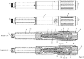
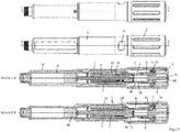
- the first embodiment of the FIGS. 1 to 6 and the second embodiment of the FIGS. 7 to 10 differ essentially in the design of a dose indicator element 10 and a slide member 11.
- the dose indicator 10 has an internal thread 10b, which in an external thread 11a of the slide member 11 ( FIG. 1 ) intervenes.
- the second embodiment has a dose indicator element 10 which has an external thread 10b which is inserted into an internal thread 11a of the housing 1 (FIG. FIG. 8 ) intervenes.
- the drive and metering device forms an injection device or is at least part of such an injection device.
- the drive and metering device has a sleeve-shaped housing 1, which has an outer sleeve 1g and an inner sleeve 1h connected thereto and arranged concentrically therewith.
- the inner sleeve 1h and the outer sleeve 1g are firmly connected via an annular web.
- the housing 1, in particular the inner sleeve 1h has an internal thread 1a, which engages in an external thread 3c of the threaded rod 3a, so that the threaded rod 3a and thus the driven member 3, screwed relative to the housing 1 and along the longitudinal axis L in the distal direction can be.
- the output member 3 has the threaded rod 3a and a plate-shaped flange 3b, which is freely rotatably attached to the distal end of the threaded rod 3a, in particular snapped.
- the threaded rod 3a has at least one guide groove 3d, which superimposes the external thread 3c and extends parallel to the longitudinal axis L.
- a sleeve-shaped rotary member 7 has at its inner circumference at least one web-shaped engaging member 7b, which engages in the guide groove 3d, whereby the rotary member 7 and the driven member 3 relative to each other are rotationally and axially displaceable.
- the rotary member 7 has on its outer circumference an annular groove 7d, into which a projection 1f formed on the inner circumference of the housing 1, in particular of the inner sleeve 1h engages, whereby the rotary member 7 is rotatable and axially fixed relative to the housing 1.
- Rotation of the rotary member 7 causes rotation of the driven member 3, whereby the driven member 3 is movable along the longitudinal axis L due to the threaded engagement with the housing 1.
- the output member 3 is moved in the distal direction when the rotary member 7 is rotated relative to the housing 1 in a second rotational direction about the longitudinal axis L.
- the rotary member 7 has a second coupling structure 7a in the form of an external toothing.
- the housing 1, in particular the inner sleeve 1h, has an engagement structure on its outer circumference, this engagement structure and a groove or rib-shaped longitudinal guide 11e formed on the inner circumference of the sliding member 11 meshing in such a way that the displacement member 11 is secured against rotation relative to the housing 1 about the longitudinal axis L. along the longitudinal axis L is displaceable.
- the displacement member 11 has on its inner circumference an internal toothing 11f, in which a locking means 7c, which is resiliently formed on the rotary member 7, engages.
- the latching means 7c has a latching arm, on the outside of which an engagement cam is arranged, which engages in the internal toothing 11f.
- the locking means 7c slides over the internal toothing 11f, whereby the product distribution can be signaled, for example, by means of an acoustic and / or tactile signal.
- the engagement of the locking means 7c in the internal toothing 11f may be in a variant such that the rotary member 7 can be rotated relative to the housing 1 or the displacement member 11 only after overcoming a certain limit torque.
- the engagement of the locking means 7c in the internal toothing 11f prevents the driven member 3 from unintentionally rotating relative to the housing 1, such as by vibrations during the transport of the drive and metering device.
- the limit torque is designed so that it can be easily overcome by a torque which is provided by a rotationally biased drive spring 5 during the product distribution.
- the locking means 7c serve the internal toothing 11f only for generating an acoustic and / or tactile signal during product distribution.
- the internal toothing 11f forms a seventh coupling structure, which engages in the external toothing of the second coupling structure 7a.
- the second clutch structure 7a and the seventh clutch structure 11f form a fourth clutch 7a, 11f.
- the rotary member 7 may have an eighth coupling structure in the form of a toothing, in particular external toothing, which is separate from the second coupling structure 7a, for example.
- the seventh coupling structure 11f and the eighth coupling structure may form the fourth coupling.
- the fourth clutch 7a, 11f is engaged when the actuator 8 is inoperative and disengaged when the actuator 8 is operated.
- the fourth clutch 7a, 11f is engaged, the seventh clutch structure 11f and the second clutch structure 7a or the eighth clutch structure are rotationally engaged with each other.
- the sliding member 11 has at its proximal end an annular groove 11d, in which a projection 4g engages the inner periphery of a drive member 4, whereby the drive member 4 is rotatable relative to the shift member 11 and axially fixed.
- a displacement of the drive member 4 along the longitudinal axis L thus also causes a displacement of the slide member 11 along the longitudinal axis L.
- the drive member 4 has a first coupling structure 4a in the form of an internal toothing, which forms a first coupling 4a, 7a with the second coupling structure 7a.
- the drive member 4 is displaceable from a disengaged position, in which the first coupling structure 4a and the second coupling structure 7a do not mesh, into an engaged position along the longitudinal axis L, in which the first coupling structure 4a and the second coupling structure 7a engage in a form-fitting manner.
- the drive member 4 is rotatable relative to the rotary member 7 about the longitudinal axis L when the first clutch 4a, 7a is disengaged, and relative to the rotary member 7 rotationally about the longitudinal axis L when the first clutch 4a, 7a is engaged.
- the drive member 4 has a latching structure 4d, which is resiliently formed on the drive member 4.
- the latching structure 4d has at least one tooth, which is in engagement with a toothing, in particular the second coupling structure 7a of the rotary member 7, when the first clutch 4a, 7a is disengaged.
- the latching structure 4d snaps over the toothing, in particular the second coupling structure 7a of the rotary member 7, when the drive member 4 is rotated relative to the rotary member 7 during the setting of a dispensed product dose in a first rotational direction and / or a second rotational direction.
- click noises are generated, which tactile and / or audible signal the user setting the dose and on the other hand given discrete angular positions for the drive member 4 with respect to the rotary member 7.
- the engagement of the latching structure 4d in the rotary member 7 with respect to the engagement of the latching means 7c in the internal teeth 11f be designed so that upon rotation of the drive member 4 relative to the rotary member 7 thereby the torque applied to the rotary member 7 is less than the limit torque necessary for rotation of the rotary member 7 with respect to the slide member 11.
- the drive member 4 has a fourth coupling structure 4b, which is designed as external teeth.
- the fourth coupling structure 4b forms a second coupling 2b, 4b with a third coupling structure 2b, which is configured as internal toothing.
- Attached to the housing 1 is a sleeve-shaped dose setting member 2, wherein the dose setting member 2 is rotatable and axially fixed relative to the housing 1.
- the dose setting member 2 has an outer sleeve and an inner sleeve, which are fixedly connected to one another via a web.
- the dosage setting member 2 in particular the outer sleeve, has on its inner circumference a projection 2a, which engages in an annular groove of the housing 1, in particular the outer sleeve 1g, so that the dose setting member 2 is rotatable and axially fixed relative to the housing 1.
- the dosage setting member 2 in particular its inner sleeve, forms the third coupling structure 2b.
- the third coupling structure 2b engages positively in the fourth coupling structure 4b, when the second clutch 2b, 4b is engaged, whereby the dose setting member 2 is non-rotatably connected to the drive member 4 about the longitudinal axis L.
- the drive member 4 thus makes rotational movements of the dose setting member 2.
- the second clutch 2b, 4b is disengaged, the third clutch structure 2b and the fourth clutch structure 4b do not mesh with each other, so that the dose setting member 2 and the drive member 4 are rotatable relative to each other.
- the dose setting member 2 is rotated relative to the housing 1 to increase the dose in a first direction of rotation and to reduce the correction of the dose in a second direction of rotation.
- the second clutch 2b, 4b is engaged, whereby the drive member 4 participates in the rotational movements of the dose setting member 2.
- the dosage setting member 2 is arranged at the proximal end of the housing 1 and is graspable by the user of the device and rotatable relative to the housing 1.
- the proximal end of the drive and metering device is formed by an actuator 8, which is designed as an actuating button.
- the actuator 8 may be from an unactuated position (see for example Figures 3 and 9 ) in an actuated position (see for example Figures 5 un 10) are moved against the reset spring 9, thereby the reset spring 9 is tensioned.
- the reset spring 9 is a helical or helical spring, which acts as a compression spring and is supported with its distal end on the dose setting member 2 and with its proximal end on the actuating member 8.
- the actuator 8 for example, with the finger of the thumb of the hand, which surrounds the housing 1, pressed, whereby the spring 9 is tensioned.
- the biased spring 9 of the actuator 8 can slide back from the actuated position to the unactuated position.
- the actuator 8 is reciprocable relative to the dosage setting member 2 along the longitudinal axis L, namely between the actuated position and the unactuated position.
- the actuator 8 is designed in several parts and has a connecting member 8a, which has a sleeve-shaped portion which is narrowed or closed at the distal end by an inwardly projecting collar.
- the proximal end of the connecting member 8a is closed by means of a cover cap 8b, which also belongs to the actuating member 8a and forms a bearing surface for the thumb for actuating the actuating member 8.
- the actuator 8, in particular the sleeve-shaped portion of the connecting member 8a surrounds the drive spring 5 circumferentially.
- the drive spring 5 is a helically wound from a band-shaped material spring, which can also be referred to as a clock spring.
- a first section, in particular a first end of the drive spring 5, is fastened to the actuating member 8, in particular to its cylindrical section.
- a second section, in particular a second end of the drive spring 5, is fastened to the drive element 4, in particular between its proximal end 4c and a collar 4e.
- the drive spring 5 has a third section, which is elastically deformed when the spring tension changes.
- a rotation of the drive member 4 relative to the actuator 8 causes a change in the spring tension, in particular a decrease in the spring tension while delivering the potential energy stored by the spring 5 to the drive member 4 in the form of kinetic, d. H. Rotational energy.
- the drive member 4 has a particular rod or pin-shaped portion which extends through the collar at the distal end of the actuator 8 in the interior of the actuator 8 and by the drive spring 5.
- the proximal end 4c tapers towards the proximal end of the drive and metering device, for example spherical, conical or frusto-conical.
- the actuating member 8, in particular the covering cap 8e forms a contact surface 8d for the proximal end 4c of the drive member 4.
- the actuating member 8, in particular the connecting member 8a, has a sixth coupling structure 8c in the form of an outer toothing, which is formed, for example, on a projection projecting in the distal direction.
- the Abragung engages through the collar which connects the inner sleeve with the outer sleeve of the dose setting 2.
- the housing 1, in particular the outer sleeve 1g, has a fifth coupling structure 1c, which is formed as an internal toothing and forms a third coupling 1c, 8c with the sixth coupling structure 8c.
- the sixth clutch structure 8c engages positively in the fifth clutch structure 1c, as a result of which the actuating member 8 and in particular also the dose setting member 2 connected in a rotationally fixed manner to the actuating member 8 is rotationally fixed with respect to the housing 1.
- the actuator 8 and the dose setting member 2 are rotatable relative to the housing 1 when the third clutch 1c, 8c is disengaged, and the sixth clutch structure 8c and the fifth clutch structure 1c are then disengaged.
- a sleeve-shaped product container holder in particular permanently attached, in which a product container 6 is received.
- the product container 6 is a carpule in the example shown.
- the product container 6 has a container body 6a surrounding a liquid product to be administered, wherein in the container body 6a proximal to the product, a displaceable piston 6b is arranged, which bears sealingly against the inner wall of the container body 6.
- a septum 6c is formed, which can be pierced by means of a needle, which is attachable to a thread 12c of the product container holder 12. to Displacement of the piston 6b in the direction of the septum 6c, the product contained in the product container 6 is discharged via the needle.
- the product container holder 12 has a window 12d, by means of which the amount of product contained in the product container 6 can be optically monitored.
- the product container holder 12 has a recess 12 b into which a first engagement structure 1 b is snapped on the inner circumference of the housing 1, in particular the outer sleeve 1, when the product container holder 12 is attached to the housing 1.
- the product container holder 12 has an annular circumferential collar 12a on its outer circumference, which rests against the distal end of the housing 1, in particular the outer sleeve 1g, when the product container holder 12 is fastened to the housing 1.
- the product container holder 12 has on its outer circumference a cam 12e, with which a sleeve-shaped cap, which is slidable over the product container holder 12, is releasably 29nappbar.
- the cap 14 can thus be removed again and serves only to protect an optionally attached needle and / or the drug from exposure to light.
- the cap 14 has a ring on the inner circumference mounted recess 14a, in particular groove.
- the drive and metering device has a dose limiter 13 in the form of a ring segment, alternatively a ring or a nut, which has on its inner circumference a threaded portion 13b which engages in a arranged on the outer circumference of the housing 1 thread 1e, so that the dose limiter 13th can be screwed relative to the housing 4.
- the dose limiter 13 is accommodated in a groove 2c arranged on the inner circumference of the dosage setting member 2 and extending along the longitudinal axis L, the groove flanks enclosing the ring segment-shaped dose limiter 13 laterally.
- the dose limiter 13 On the outer circumference, the dose limiter 13 has a groove-shaped engagement member 13a, in which a longitudinal guide, which protrudes from the groove bottom of the groove 2c of the dose setting member 2 and extends along the longitudinal axis L, engages. Both through the groove 2c and through the longitudinal guide of the dose limiter 13 is rotatably relative to the dose setting 2, but axially displaceable. At the dose setting member 2 or the housing 1, a stop stop is formed, of which the dose limiter 13 is spaced in proportion to the maximum amount of product to be distributed from the product container 6.
- the dose limiter 13 Since, at the dose setting, the dosage setting member 2 is rotated relative to the housing 4 and at a dose distribution is not rotated, a count can be formed by the dose limiter 13, which adds the already distributed individual doses and the currently set dose and accordingly approaches closer and closer to the stop stop of the dose setting 2 or the housing 1.
- a dose increase causes the dose limiter 13 to move toward the stop stop.
- Dose reduction causes the dose limiter 13 to be moved away from the stop stop.
- the dose limiter 13 comes into contact with the stop stop, so that a rotation of the dose setting 2 relative to the housing 1 in a rotational direction, the one Increasing the dose would result, ie in a first direction of rotation, is blocked.
- the dose indicator element 10 which is sleeve-shaped and thus can be called a dose indicating drum, has over its outer periphery a helical extending dose scale 10b corresponding to the pitch of the thread 10e, comprising a plurality of successively arranged scale values.
- the drive and metering device can be used to set a maximum dose of 80 IU, with the scale from 0 to 80 and the dose values in two steps.
- the dose indicator 10 has a circumferentially facing and acting stop surface, referred to as the zero dose stop 10e.
- the dose indicator has a circumferentially facing and acting stop surface, referred to as the maximum dose stop 10d.
- the sleeve-shaped displacement member 11 has an external thread 11a in which the internal thread 10b engages.
- the shift member 11 further includes a zero dose counter stop 11b and a maximum dose counter stop 11c.
- the thread 10b is an external thread which is in engagement with an internal thread 11a of the outer sleeve 1g of the housing 1, or generally the housing 1.
- the housing 1, in particular the outer sleeve 1g, has a zero dose counter stop 11b and a maximum dose counter stop 11c.
- the dose indicator element 10 can be screwed back and forth between a zero dose position and a maximum dose position.
- the zero dose stop 10e in cooperation with the zero dose counter stop 11b, prevents rotation of the dose indicating element 10 in a second rotational direction, namely in a rotational direction that would cause a dose smaller than zero to be set.
- the dose indicator 10 In this zero dose position, the dose indicator 10 is in the opposite, d. H. rotatable first direction of rotation.
- the maximum dose stop 10d In the maximum dose position, the maximum dose stop 10d, in cooperation with the maximum dose counteracting stop 11c, prevents rotation of the dose indicating element 10 in the first direction of rotation, which would cause the dose to be increased beyond the maximum adjustable value.
- the rotation in the second direction of rotation is possible in the maximum dose position.
- the housing 1, in particular the outer sleeve 1g, has a pointing device 1d in the form of a window which exposes the dose scale 10a of the dose indicator element 10.
- the dose indicator 10 is rotatably connected to the drive member 4 and axially displaceably connected.
- the dose indicator element 10 at least one, in this example, a plurality of guide grooves 10c, which extend parallel to the longitudinal axis L. In these guide grooves 10c engage projections 4f on the outer circumference of the drive member 4 a.
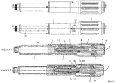
- the first and second embodiments are shown in their delivery or initial state with the cap 14 removed.
- the actuator 8 is not actuated.
- the dose appears zero, that is, the dose indicating element 10 is in its zero dose position.
- the drive spring 5 is biased with so much energy that the amount of product contained in the product container 6 can be completely released with the energy stored in the spring 5 by moving the piston 6b, in particular in one or more individual distributions, between each of which a new dose setting takes place without tensioning the spring 5.
- the first clutch 4a, 7a are disengaged, the second clutch 2b, 4b engaged and the third clutch 1c, 8c disengaged.
- the drive spring 5 is kinematically connected between the drive member 4 and the dose setting member 2.
- the clutch 2b, 4b prevents the drive member 4 from being rotated relative to the dose setting member 2.
- the dosage setting member 2 is rotated relative to the housing 1 in a first rotational direction, whereby the drive member 4, the spring 5 and the dose indicator 10 are also rotated.
- the rotation causes the dose indicator element 10 to be unscrewed from the zero dose counter-stop 11b, with the distance measured between the zero-dose stop 10e and the zero-dose counter-abutment 11b along the screwing curve being proportional to the product dose to be dispensed.
- the pointing device 1d the currently set dose can be read in IU.
- the dose setting member 2 can be rotated by rotating in the opposite direction of rotation, i. H. are rotated in the second direction of rotation relative to the housing 1, whereby the distance between the zero dose stop and the maximum dose stop decreases and the readable dose is reduced.
- the actuator 8 is moved, for example, with the thumb of the hand, which surrounds the housing 1, from an unactuated position (for example FIGS. 4 and 9 ) in an actuated position (for example Figures 5 and 10 ), whereby the reset spring 9 is tensioned.
- the third clutch 1c, 8c is first engaged, so that the drive spring 5 is kinematically connected between the housing 1 and the drive member 4.
- the dose setting member 2 is then also secured against rotation with respect to the housing 1.
- the dose indicator 10 is simultaneously screwed back to its zero dose position.
- the zero dose stop 10e abuts against the zero dose counter stop 11b, the set dose is completely released, stopping the zero dose stopper 10e at the zero dose counter stop 11b to stop the dose indicating element 10 from rotating, thereby also stopping the drive member 4 from rotating in the second rotational direction becomes.
- This situation is for example in FIG. 5 shown.
- the reset spring 9 returns the actuator 8 to its unactuated position with the first clutch 4a, 7a, the second clutch 2b, 4b, the third clutch 1c, 8c, and the fourth clutch 7a, 11f be returned to their original position.
- a dose to be distributed By rotating the dose setting member 2 in the first direction of rotation can now be set again a dose to be distributed, which can be distributed by actuation of the actuator 8, etc.
- a product amount which is less than the maximum with the device divisible dose in this example less than 80 IU, suggests the dose limiter 13 at its end stop when the dose setting member 2 is rotated in the first direction of rotation before the maximum dose stop 10d abuts on the maximum dose counteracting stop 11c. This prevents the user of the device from being able to inject less product than he has set with the device.
Landscapes
- Health & Medical Sciences (AREA)
- Vascular Medicine (AREA)
- Engineering & Computer Science (AREA)
- Anesthesiology (AREA)
- Biomedical Technology (AREA)
- Heart & Thoracic Surgery (AREA)
- Hematology (AREA)
- Life Sciences & Earth Sciences (AREA)
- Animal Behavior & Ethology (AREA)
- General Health & Medical Sciences (AREA)
- Public Health (AREA)
- Veterinary Medicine (AREA)
- Infusion, Injection, And Reservoir Apparatuses (AREA)
Description
Die Erfindung betrifft eine Antriebs- und Dosiervorrichtung für eine Injektionsvorrichtung zum Verabreichen bzw. Ausschütten eines flüssigen Produkts, insbesondere eines Medikaments, wie zum Beispiel Insulin zur Diabetestherapie. Im Besonderen betrifft die Erfindung auch eine Injektionsvorrichtung, welche eine solche Antriebs- und Dosiervorrichtung aufweist.The invention relates to a drive and metering device for an injection device for administering or pouring out a liquid product, in particular a medicament, such as insulin for diabetes therapy. In particular, the invention also relates to an injection device having such a drive and metering device.
Der Begriff "Medikament" umfasst hier jede fließfähige medizinische Formulierung, welche geeignet ist zur kontrollierten Verabreichung durch ein Mittel, wie z. B. eine Kanüle oder Hohlnadel, hindurch, beispielsweise umfassend eine Flüssigkeit, eine Lösung, ein Gel oder eine feine Suspension, welche(s) einen oder mehrere medizinische Wirkstoffe enthält. Medikament kann eine Zusammensetzung mit einem einzigen Wirkstoff oder eine vorgemischte oder co-formulierte Zusammensetzung mit mehreren Wirkstoffen aus einem einzelnen Behälter sein. Medikament umfasst Arzneien wie Peptide (z.B. Insuline, Insulin enthaltende Medikamente, GLP-1 enthaltende sowie abgeleitete oder analoge Zubereitungen), Proteine und Hormone, biologisch gewonnene oder aktive Wirkstoffe, Wirkstoffe auf Basis von Hormonen oder Genen, Nährformulierungen, Enzyme und weitere Substanzen sowohl in fester (suspendierter) oder flüssiger Form aber auch Polysaccharide, Vaccine, DNS oder RNS oder Oglionukleotide, Antikörper oder Teile von Antikörpern sowie geeignete Basis-, Hilfs- und Trägerstoffe.As used herein, the term "medicament" includes any fluid medical formulation suitable for controlled administration by an agent, such as an oral fluid. A cannula or hollow needle, for example comprising a liquid, a solution, a gel or a fine suspension containing one or more medicinal agents. Drug may be a single drug composition or a premixed or co-formulated multi-drug composition from a single container. Drug includes drugs such as peptides (eg, insulins, insulin-containing drugs, GLP-1 containing as well as derived or analogous preparations), proteins and hormones, biologically derived or active agents, hormone or gene based drugs, nutritional formulas, enzymes, and other substances both in the art solid (suspended) or liquid form but also polysaccharides, vaccines, DNA or RNA or Oglionukleotide, antibodies or parts of antibodies and suitable base, excipients and carriers.
Aus dem Stand der Technik, wie zum Beispiel der
Aus der
Die
Die
Der Erfindung liegt die Aufgabe zugrunde, eine Antriebs- und Dosiervorrichtung für eine Injektionsvorrichtung anzugeben, die dem Verwender eine einfache Verwendung der Vorrichtung, insbesondere eine einfache Dosiseinstellung erlaubt und dennoch eine kompakte Bauweise ermöglicht.The invention has for its object to provide a drive and metering device for an injection device, which allows the user a simple use of the device, in particular a simple dose setting and yet allows a compact design.
Die Aufgabe wird durch die Merkmale des Anspruchs 1 gelöst. Vorteilhafte Weiterbildungen ergeben sich aus den abhängigen Ansprüchen, der Beschreibung und den Figuren.The object is solved by the features of
Die Erfindung geht von einer Antriebs- und Dosiervorrichtung für eine Injektionsvorrichtung zum Verabreichen eines flüssigen Medikaments oder Produkts aus. Die Antriebs- und Dosiervorrichtung weist ein Gehäuse auf. Das Gehäuse ist vorzugweise hülsenförmig und/oder länglich ausgebildet. Das Gehäuse kann sich zum Beispiel entlang seiner Längsachse erstrecken.The invention is based on a drive and metering device for an injection device for administering a liquid medicament or product. The drive and metering device has a housing. The housing is preferably sleeve-shaped and / or elongated. The housing may extend along its longitudinal axis, for example.
Das Gehäuse kann optional einen Produktbehälter aufnehmen oder selbst den Produktbehälter bilden. Das Gehäuse kann ein- oder mehrteilig sein. Zum Bespiel kann das Gehäuse einen proximalen Gehäuseteil bilden, der im Wesentlichen die Antriebs- und Dosiervorrichtung bildet, d. h. einen Antriebs- und Dosiermechanismus umfasst oder aufweist. Das Gehäuse kann ferner einen Produktbehälterhalter aufweisen, der den Produktbehälter, wie zum Beispiel eine Karpule, aufnimmt und mit dem Gehäuse oder dem proximalen Gehäuseteil verbunden ist. Diese Verbindung kann derart sein, dass der Produktbehälterhalter und das Gehäuse oder das proximale Gehäuseteil nach dem Verbinden unlösbar, d. h. nur noch durch Zerstörung von Verbindungselementen lösbar ist. Eine solche Ausführung ist insbesondere bei Einweginjektionsvorrichtungen von Vorteil, die nach dem das in dem Produktbehälter enthaltene Produkt vollständig ausgeschüttet ist, als Ganzes entsorgt werden. Alternativ kann der Produktbehälterhalter auch lösbar an dem Gehäuse befestigt werden, wodurch es möglich ist, die Antriebs- und Dosiervorrichtung ggf. mehrfach zu verwenden, d. h. einen leeren Produktbehälter gegen einen gefüllten Produktbehälter auszutauschen.The housing can optionally accommodate a product container or even form the product container. The housing can be one or more parts. For example, the housing may have a form a proximal housing part, which essentially forms the drive and metering device, that includes or comprises a drive and metering mechanism. The housing may further include a product container holder receiving the product container, such as a carpule, and connected to the housing or proximal housing part. This connection can be such that the product container holder and the housing or the proximal housing part after connection unsolvable, that is only solvable by destruction of fasteners. Such an embodiment is particularly advantageous in the case of disposable injection devices which, after the product contained in the product container has been completely poured out, are discarded as a whole. Alternatively, the product container holder can also be releasably secured to the housing, whereby it is possible to use the drive and metering device, if necessary several times, that is, to replace an empty product container with a filled product container.
Das Gehäuse dient vorzugsweise dazu, vom Verwender der Vorrichtung ergriffen zu werden. Insbesondere kann das Gehäuse eine im Wesentlichen zylindrische Form aufweisen. Das Gehäuse kann optional eine Zeigeeinrichtung, insbesondere ein Fenster aufweisen, mittels der oder durch welches eine aktuell eingestellte Dosis, vorzugsweise von einer Dosisskala eines Dosiseinstellelements, welches mit der Vorrichtung optional vorhanden sein kann, ablesbar ist.The housing preferably serves to be gripped by the user of the device. In particular, the housing may have a substantially cylindrical shape. The housing may optionally have a pointing device, in particular a window, by means of which or by which a currently set dose, preferably from a dose scale of a dose setting element, which may optionally be present with the device, can be read.
Die Antriebs- und Dosiervorrichtung umfasst ein Dosiseinstellglied, das zum Beispiel als Dosierknopf ausgebildet ist. Das Dosiseinstellglied ist vorzugsweise vom Verwender (Patient, Arzt, medizinisches Hilfspersonal) der Antriebs- und Dosiervorrichtung greifbar und bildet vorzugsweise eine äußere, insbesondere von außen zugängliche Oberfläche der Antriebs- und Dosiervorrichtung. Für die Einstellung der auszuschüttenden oder zu verabreichenden Dosis wird das Dosierglied vorzugsweise vom Verwender ergriffen und relativ zu dem Gehäuse und insbesondere der optional vorhandenen Zeigeeinrichtung um eine Drehachse, die vorzugsweise der Längsachse der zum Beispiel länglich ausgestalteten Antriebs- und Dosiervorrichtung entspricht, verdreht. Das zum Beispiel hülsenförmige Dosiseinstellglied kann vorzugsweise axialfest mit dem Gehäuse verbunden, insbesondere entlang der Längsachse des Gehäuses verschiebefest sein, wodurch vorteilhaft die intuitive Handhabung der Vorrichtung durch den Verwender erleichtert wird, da er lediglich eine Drehbewegung des Dosierglieds für die Dosiseinstellung auszuführen braucht.The drive and metering device comprises a dose setting member, which is designed for example as a Dosierknopf. The dose setting member is preferably accessible to the user (patient, doctor, medical auxiliaries) of the drive and metering device and preferably forms an outer, in particular accessible from the outside surface of the drive and metering device. For setting the dose to be dispensed or administered, the dosing member is preferably gripped by the user and rotated relative to the housing and in particular the optionally present pointing device about an axis of rotation, which preferably corresponds to the longitudinal axis of, for example elongated drive and metering device. The sleeve-shaped dose setting member, for example, may be axially fixed to the housing, in particular displaceable along the longitudinal axis of the housing, thereby advantageously facilitating the intuitive handling of the device by the user since it only needs to perform a rotational movement of the dose setting dosing member.
Die Antriebs- und Dosiervorrichtung umfasst ein in dem Gehäuse aufgenommenes Abtriebsglied, welches vorzugsweise als Kolbenstange ausgestaltet sein kann. Das insbesondere längliche Abtriebsglied erstreckt sich vorzugsweise entlang der Längsachse der Antriebs- und Dosiervorrichtung. Das distale Ende des Abtriebsglieds kann zum Beispiel einen tellerförmigen Flansch aufweisen. Das distale Ende des Abtriebsglieds ist so angeordnet, dass es auf einen Kolben eines Produktbehälters, der an der Antriebs- und Dosiervorrichtung befestigbar ist, insbesondere mittels des Produktbehälterhalters, wirken kann. Das Abtriebsglied kann den Kolben des Produktbehälters zur Ausschüttung des Produkts in dem Produktbehälter verschieben, wenn das Abtriebsglied relativ zu dem Gehäuse in die distale Richtung bewegt wird.The drive and metering device comprises a driven member received in the housing, which can preferably be designed as a piston rod. The particular elongate output member preferably extends along the longitudinal axis of the drive and metering device. The distal end of the output member may, for example, have a dish-shaped flange. The distal end of the driven member is arranged so that it can act on a piston of a product container, which can be fastened to the drive and metering device, in particular by means of the product container holder. The output member may displace the piston of the product container to dispense the product in the product container when the output member is moved in the distal direction relative to the housing.
Die Antriebs- und Dosiervorrichtung umfasst ein Antriebsglied, welches relativ zu dem Gehäuse und vorzugsweise um die Längsachse drehbar ist und während der Produktausschüttung so mit dem Abtriebsglied gekoppelt ist, dass eine Drehung des Antriebsglieds bewirkt, dass das Abtriebsglied relativ zu dem Gehäuse in die distale Richtung bewegt wird.The drive and metering device includes a drive member which is rotatable relative to the housing and preferably about the longitudinal axis and is coupled to the output member during product delivery such that rotation of the drive member causes the output member to move relative to the housing in the distal direction is moved.
Die Antriebs- und Dosiervorrichtung umfasst erfindungsgemäß eine rotatorische oder mit einem Drehmoment vorgespannte Antriebsfeder, die während der Einstellung der Produktdosis, insbesondere wenn ein Betätigungsglied unbetätigt ist, zwischen das Dosiseinstellglied und das Antriebsglied geschaltet ist, wobei das Dosiseinstellglied während der Einstellung der Produktdosis, insbesondere wenn das Betätigungsglied unbetätigt ist, verdrehfest mit dem Antriebsglied gekoppelt ist. Hierdurch wird vorteilhaft bewirkt, dass während der Einstellung der auszuschüttenden Produktdosis eine Drehung des Antriebsglieds relativ zu dem Dosiseinstellglied, vorzugsweise in eine erste und zweite Drehrichtung verhindert wird. Durch die erfindungsgemäße Anordnung der Antriebsfeder zwischen Dosiseinstellglied und Antriebsglied kann der Bereich um das Abtriebsglied platzsparender ausgelegt werden bzw. kann mehr Platz für evtl. zusätzliche Bauteile bereitgestellt werden, welche der Antriebs- und Dosiervorrichtung zum Beispiel weitere Funktionen verleihen. Da die vorgespannte Antriebsfeder während der Dosiseinstellung nicht weiter vorgespannt wird, wird es dem Verwender ermöglicht, eine Dosiseinstellung mit wenig Kraftaufwand vorzunehmen. Ein Spannen oder Entspannen der Antriebsfeder, die während der Einstellung der Produktdosis zwischen das Dosiseinstellglied und das Antriebsglied geschaltet ist, wird vorteilhaft dadurch verhindert, dass das Dosiseinstellglied während der Einstellung der Produktdosis verdrehfest mit dem Antriebsglied gekoppelt ist. Ein durch die rotatorisch vorgespannte Antriebsfeder, die auch als Dreh- oder Torsionsfeder bezeichnet werden kann, zwischen dem Dosiseinstellglied und dem Antriebsglied wirkendes Drehmoment, welches versucht, dass Antriebsglied relativ zu dem Dosiseinstellglied zu verdrehen, kann das Antriebsglied relativ zum dem Dosiseinstellglied nicht verdrehen, da das Dosiseinstellglied während der Einstellung der Produktdosis verdrehfest mit dem Antriebsglied gekoppelt ist. Insbesondere wird während des Einstellens der Dosis bei der Drehung des Dosiseinstellglieds in eine erste Drehrichtung oder/und in eine zweite Drehrichtung die Antriebsfeder weder gespannt noch entspannt.The drive and metering device according to the invention comprises a rotary or torque-biased drive spring, which is connected between the dose setting and the drive member during adjustment of the product dose, in particular when an actuator is unactuated, the dose setting during adjustment of the product dose, in particular the actuator is unactuated, is rotationally coupled to the drive member. This advantageously has the effect that, during the setting of the dose of product to be distributed, rotation of the drive member relative to the dose setting member, preferably in a first and second direction of rotation, is prevented. The inventive arrangement of the drive spring between dose setting and drive member, the area around the output member can be designed to save space or more space can be provided for any additional components that give the drive and metering, for example, other functions. Since the preloaded power spring is not biased during the dose setting, it allows the user to make a dose setting with little effort. A cocking or relaxing of the power spring during adjustment the product dose is connected between the dose setting and the drive member is advantageously prevented by the dose setting member is rotationally coupled to the drive member during adjustment of the product dose. A torque acting through the rotationally biased drive spring, which may also be referred to as a torsion spring, between the dose setting member and the drive member which attempts to rotate the drive member relative to the dose setting member may not twist the drive member relative to the dose setting member the dosage setting member is rotationally coupled to the drive member during adjustment of the product dose. In particular, during adjustment of the dose during the rotation of the dose setting member in a first direction of rotation and / or in a second direction of rotation, the drive spring is neither tensioned nor relaxed.
Die mindestens eine Antriebsfeder, welche als Ausschüttfeder dient, kann eine Wendel- oder Schraubenfeder sein, die als Dreh- oder Torsionsfeder wirkt. Besonders bevorzugt kann die Antriebsfeder eine spiralförmig aus einem bandförmigen Material, insbesondere Metall, gewickelte Feder sein, die zum Beispiel als Spiral- oder Uhrenfeder bezeichnet werden kann. Eine rotatorisch vorgespannte Feder versucht die Teile, an denen sie sich abstützt, relativ zueinander zu verdrehen.The at least one drive spring, which serves as a discharge spring, may be a helical or helical spring, which acts as a torsion or torsion spring. Particularly preferably, the drive spring may be a helically wound from a band-shaped material, in particular metal, wound spring, which may be referred to, for example, as a spiral or clock spring. A rotationally preloaded spring tries to twist the parts on which it is supported relative to each other.
Die Antriebsfeder ist im Auslieferungszustand der Antriebs- und Dosiervorrichtung insbesondere mit so viel Federenergie vorgespannt, dass sie die aus dem Produktbehälter maximal oder insgesamt ausschüttbare Produktmenge in mehreren Einzelausschüttungen, d. h. insbesondere in mehreren Ausschüttungen einzelner Produktdosen, insbesondere vollständig, ausschütten kann. Die Antriebs- und Dosiervorrichtung ist so ausgestaltet, dass nach jeder Einzelausschüttung oder Ausschüttung der Produktdosis die nächste auszuschüttende Dosis neu eingestellt wird. Im Gegensatz zu Ausführungen, bei denen eine Antriebsfeder bei jeder Dosiseinstellung neu vorgespannt wird, kann durch die mit der für die Ausschüttung der maximal aus dem Produktbehälter ausschüttbaren Produktmenge erforderlichen Energie vorgespannte Feder eine einfachere Dosiseinstellung erreicht werden, da das für die Dosiseinstellung relativ zu dem Gehäuse drehbare Dosiseinstellglied dann einfacher drehbar ist, weil die Feder bei der Dosiseinstellung nicht vorgespannt werden braucht. Dies erhöht den Anwendungskomfort für den Verwender der Vorrichtung.The drive spring is biased in the delivery state of the drive and metering device, in particular with so much spring energy that it can distribute the maximum or total distributable from the product container product quantity in several individual distributions, ie in particular in several distributions of individual product cans, in particular completely. The drive and metering device is designed so that after each individual distribution or distribution of the product dose, the next dose to be dispensed is readjusted. In contrast to embodiments in which a drive spring is re-biased at each dose setting, a simpler dose setting can be achieved by the energy-preloaded spring required to dispense the maximum amount of product dispensed from the product container, as that for dose adjustment relative to the housing rotatable dose setting then easier to turn, because the spring need not be biased at the dose setting. This increases the ease of use for the user of the device.
Das Dosiseinstellglied und das Antriebsglied können während der Einstellung der Produktdosis miteinander verdreht werden, insbesondere relativ zu dem Abtriebsglied und/oder relativ zu dem Gehäuse. Bevorzugt ist, dass eine Drehung des Dosiseinstellglieds und vorzugsweise auch das Antriebsglieds während der Einstellung der Produktdosis in eine erste Drehrichtung eine Erhöhung der auszuschüttenden Dosis bewirkt und in eine zweite, der ersten Drehrichtung entgegengesetzte Drehrichtung eine Verringerung der auszuschüttenden Produktdosis bewirkt. In Ausführungsformen, in denen eine Dosisanzeige vorgesehen ist, kann während der Drehung in die erste Drehrichtung ein Hochzählen von Skalenwerten in einer Zeigeeinrichtung wahrgenommen werden, wobei während der Drehung in die zweite Drehrichtung ein Runterzählen der Skalenwerte in der Zeigeeinrichtung wahrgenommen werden kann.The dose setting member and the drive member may be rotated together during adjustment of the product dosage, in particular relative to the output member and / or relative to the housing. It is preferred that a rotation of the dose setting member and preferably also the drive member during the setting of the product dosage in a first rotational direction causes an increase in the dose to be distributed and causes a second, the first rotational direction opposite direction of rotation, a reduction of the dispensed product dose. In embodiments where a dose indication is provided, incrementing scale values in a pointing device may be sensed during rotation in the first direction of rotation, and during rotation in the second direction of rotation, counting down of the scale values in the pointing device may be perceived.
Vorzugsweise kann die Bewegung betreffend, d. h. kinematisch zwischen dem Antriebsglied und dem Abtriebsglied ein Rotationsglied angeordnet sein. Das bevorzugt hülsenförmige Rotationsglied kann das Abtriebsglied umgeben. Das Rotationsglied ist vorzugsweise axialfest und drehbar mit dem Gehäuse verbunden. Vorzugsweise greifen das Gehäuse oder ein gehäusefestes Teil und das Rotationsglied so ineinander, dass das Rotationsglied relativ zu dem Gehäuse drehbar und axialfest ist.Preferably, the movement concerning, i. H. be arranged kinematically between the drive member and the output member, a rotary member. The preferably sleeve-shaped rotary member can surround the output member. The rotary member is preferably axially fixed and rotatably connected to the housing. Preferably, the housing or a housing-fixed part and the rotary member engage each other such that the rotary member is rotatable and axially fixed relative to the housing.
In einer ersten Variante kann das Rotationsglied in einem Gewindeeingriff mit einem Gewinde des Abtriebsglieds sein. Zum Beispiel kann das Abtriebsglied ein Innengewinde und das Rotationsglied ein Außengewinde aufweisen, die ineinandergreifen. Bevorzugt kann das Rotationsglied ein Innengewinde und das Abtriebsglied ein Außengewinde aufweisen, die ineinandergreifen.In a first variant, the rotary member can be in threaded engagement with a thread of the driven member. For example, the output member may have an internal thread and the rotary member may have an external thread that engage with each other. Preferably, the rotary member having an internal thread and the output member having an external thread, which engage with each other.
Das Abtriebsglied kann mit einer gehäusefesten Führung der Antriebs- und Dosiervorrichtung in einem Eingriff sein. Zum Beispiel kann die gehäusefeste Führung ein Nocken oder ein unrunder Querschnitt sein, der in eine Nut oder in einen unrunden Querschnitt des Abtriebsglieds eingreift. Zum Beispiel kann sich die Nut oder der unrunde Querschnitt parallel zur Längsachse des länglichen Abtriebsglieds erstrecken. Die gehäusefeste Führung kann von dem Gehäuse selbst oder einem dreh- und axialfest mit dem Gehäuse verbundenen Teil gebildet werden. Dieses Teil kann permanent oder zumindest während der Produktausschüttung dreh- und axialfest mit dem Gehäuse verbunden sein. Die Nut oder der unrunde Querschnitt des Abtriebsglieds kann sich alternativ zu der Ausführung, in der sie bzw. er sich parallel zur Längsachse erstreckt, helix- oder wendelförmig um die Längsachse erstrecken, jedoch mit einer anderen Steigung als das Gewinde. Diese Varianten bewirken, dass eine Drehung des Rotationsglieds eine Bewegung des Abtriebsglieds in die distale Richtung bewirkt, insbesondere wenn das Rotationsglied in die zweite Drehrichtung relativ zu dem Gehäuse gedreht wird. Hierbei kann sich das Abtriebsglied entweder in die distale Richtung schrauben, insbesondere wenn die Nut oder der unrunde Querschnitt des Abtriebsglieds helixförmig ist, oder linear verschieben, insbesondere wenn die Nut oder der unrunde Querschnitt sich parallel zur Längsachse erstreckt.The output member may be engaged with a housing fixed guide of the drive and metering device in an engagement. For example, the housing-fixed guide may be a cam or a non-circular cross-section which engages in a groove or in a non-circular cross-section of the driven member. For example, the groove or non-circular cross-section may extend parallel to the longitudinal axis of the elongate driven member. The housing-fixed guide can be formed by the housing itself or a rotationally and axially connected to the housing part. This part can be permanently or at least during the product distribution rotatably and axially connected to the housing. The groove or the A non-circular cross-section of the output member may, as an alternative to the embodiment in which it extends parallel to the longitudinal axis, extend helically or helically about the longitudinal axis, but with a pitch other than the thread. These variations cause rotation of the rotary member to cause movement of the output member in the distal direction, particularly when the rotary member is rotated in the second rotational direction relative to the housing. In this case, the output member can either screw in the distal direction, in particular if the groove or the non-circular cross section of the output member is helical, or linearly move, in particular if the groove or the non-circular cross section extends parallel to the longitudinal axis.
In einer zweiten Variante kann ein gehäusefestes Innengewinde in einem Gewindeeingriff mit einem Außengewinde des Abtriebsglieds sein. Das Abtriebsglied und das Rotationsglied können so ineinandergreifen, dass das Abtriebsglied relativ zum Rotationsglied drehfest und entlang der Längsachse verschiebbar ist. Eine Drehung des Rotationsglieds bewirkt eine Schraubbewegung des Abtriebsglieds in die distale Richtung. Das Abtriebsglied kann einen unrunden Querschnitt oder eine Nut aufweisen, der bzw. die in einem Eingriff mit einem unrunden Querschnitt oder einer Abragung des Rotationsglieds ist.In a second variant, a housing-fixed internal thread may be in threaded engagement with an external thread of the output member. The driven member and the rotary member can engage in such a way that the driven member is rotatable relative to the rotary member and slidable along the longitudinal axis. A rotation of the rotary member causes a screwing movement of the driven member in the distal direction. The driven member may have a non-circular cross-section or a groove which is in engagement with a non-circular cross-section or a projection of the rotary member.
Allgemein bevorzugt bewirkt eine Drehung des Antriebsglieds während der Produktausschüttung oder wenn das Betätigungsglied betätigt ist, relativ zu dem Gehäuse und/oder dem Dosiseinstellglied, dass das Abtriebsglied relativ zu dem Gehäuse in die distale Richtung bewegt wird. Insbesondere bewirkt eine Drehung des Antriebsglieds relativ zu dem Gehäuse und/oder dem Dosiseinstellglied, dass das kinematisch zwischen dem Antriebsglied und dem Abtriebsglied angeordnete Rotationsglied mit dem Antriebsglied mitgedreht wird, d. h. relativ zu dem Gehäuse und/oder dem Dosiseinstellglied bewegt wird. Die Drehung des Rotationsglieds bewirkt eine Bewegung des Abtriebsglieds in die distale Richtung. Das Abtriebsglied wird insbesondere nur während der Produktausschüttung relativ zu dem Gehäuse in die distale Richtung bewegt.Generally, rotation of the drive member during product dispensing or when the actuator is actuated relative to the housing and / or dose setting member causes the output member to be moved in the distal direction relative to the housing. In particular, rotation of the drive member relative to the housing and / or dose setting member causes the rotary member, which is kinematically disposed between the drive member and the output member, to be rotated with the drive member, i. H. is moved relative to the housing and / or dose setting. The rotation of the rotary member causes movement of the output member in the distal direction. In particular, the output member is moved in the distal direction relative to the housing only during product dispensing.
Die Antriebs- und Dosiervorrichtung kann ein Betätigungsglied zum Beispiel in der Gestalt eines Betätigungsknopfs aufweisen. Das Betätigungsglied kann insbesondere am proximalen Ende der Antriebs- und Dosiervorrichtung angeordnet sein oder das proximale Ende der Antriebs- und Dosiervorrichtung bilden. Das Betätigungsglied kann eine äußere Oberfläche der Antriebs- und Dosiervorrichtung bilden und/oder von außen zugänglich sein. Das Betätigungsglied lässt sich vorteilhaft mit dem Daumen der Hand, die das Gehäuse umgreift, betätigen, insbesondere drücken. Durch Loslassen des Betätigungsglieds kann die Betätigung beendet werden. Unter "betätigen" wird die Verschiebung des Betätigungsglieds in die Antriebs- und Dosiervorrichtung bzw. das Gehäuse oder Dosiseinstellglied, insbesondere in die distale Richtung verstanden, wodurch eine Produktausschüttung bewirkt werden kann. Das Betätigungsglied ist vorteilhalft relativ zu dem Dosiseinstellglied entlang der Längsachse verschiebbar und kann insbesondere von dem Dosiseinstellglied axial verschiebbar aufgenommen sein.The drive and metering device may comprise an actuator, for example in the form of an actuating button. The actuator may in particular be arranged at the proximal end of the drive and metering device or form the proximal end of the drive and metering device. The actuator may have an outer surface form the drive and metering device and / or be accessible from the outside. The actuator can be advantageous with the thumb of the hand, which engages around the housing, actuate, in particular press. By releasing the actuator, the operation can be terminated. By "actuate" is meant the displacement of the actuator into the drive and metering device or the housing or dose setting member, in particular in the distal direction, whereby a product discharge can be effected. The actuator is vorteilhalft relative to the dosage setting along the longitudinal axis displaceable and can be taken in particular axially displaceable by the dose setting.
Das Betätigungsglied kann aus einer unbetätigten Position, die es während der Einstellung der auszuschüttenden Produktdosis einnimmt, in eine betätigte Position, die es während der Produktausschüttung einnimmt, verschiebbar sein. Anders ausgedrückt, ist das Betätigungsglied während der Produktausschüttung in der betätigten Position und während der Dosiseinstellung in der unbetätigten Position.The actuator may be displaceable from an unactuated position which it occupies during the adjustment of the product dose to be dispensed to an actuated position which it occupies during product dispensing. In other words, during product dispensing, the actuator is in the actuated position and in the unactuated position during dose setting.
Das Betätigungsglied kann vorteilhaft gegen die Kraft einer Feder, insbesondere einer Rücksetz- oder Kupplungsfeder verschiebbar, insbesondere betätigbar sein, wobei diese Feder so auf das Betätigungsglied wirkt, dass sie gespannt wird, wenn das Betätigungsglied aus seiner unbetätigten Position in seine betätigte Position verschoben wird. Mittels der Rücksetzfeder wird das Betätigungsglied aus seiner betätigten Position in seine unbetätigte Position zurückgesetzt oder verschoben, insbesondere mit einer Bewegung in die proximale Richtung relativ zu dem Dosiseinstellglied oder/und dem Gehäuse.The actuator may advantageously against the force of a spring, in particular a reset or clutch spring slidably, in particular actuated, said spring acts on the actuator so that it is tensioned when the actuator is moved from its unactuated position to its actuated position. By means of the reset spring, the actuator is reset or shifted from its actuated position to its unactuated position, in particular with a movement in the proximal direction relative to the dose setting member and / or the housing.
Die Antriebs- und Dosiervorrichtung kann vorzugsweise eine erste Kupplung aufweisen, welche zwischen, insbesondere kinematisch zwischen dem Antriebsglied und dem Abtriebsglied angeordnet ist. Insbesondere kann die erste Kupplung zwischen dem Antriebsglied und dem Rotationsglied angeordnet sein. Die erste Kupplung ist während der Einstellung der Produktdosis oder bei unbetätigtem Betätigungsglied ausgekuppelt, wodurch dem Antriebsglied erlaubt wird, relativ zu dem Abtriebsglied verdreht zu werden. Während der Produktausschüttung oder bei betätigtem Betätigungsglied ist die erste Kupplung eingekuppelt. Hierdurch wird insbesondere erreicht, dass das Rotationsglied und das Antriebsglied verdrehfest verbunden sind. Das Rotationsglied kann somit mit dem Antriebsglied mitgedreht werden. Die erste Kupplung kann einer erste Kupplungsstruktur, welche verdrehgesichert mit dem Antriebsglied verbunden ist, insbesondere von dem Antriebsglied gebildet wird, und eine zweite Kupplungsstruktur, welche verdrehfest mit dem Rotationsglied verbunden ist, insbesondere von dem Rotationsglied gebildet wird, umfassen. Die erste Kupplungsstruktur kann eine Verzahnung sein oder aufweisen, wobei die zweite Kupplungsstruktur eine Verzahnung sein oder aufweisen kann. Die Verzahnungen der ersten Kupplungsstruktur und der zweiten Kupplungsstruktur können formschlüssig ineinandergreifen, wenn die erste Kupplung eingekuppelt ist. Zum Beispiel kann die erste Kupplungsstruktur eine Innenverzahnung sein, wobei die zweite Kupplungsstruktur eine Außenverzahnung sein kann. Alternativ kann die erste Kupplungsstruktur eine Außenverzahnung sein, wobei die zweite Kupplungsstruktur eine Innenverzahnung sein kann.The drive and metering device may preferably have a first clutch, which is arranged between, in particular kinematically between the drive member and the output member. In particular, the first coupling between the drive member and the rotary member may be arranged. The first clutch is disengaged during adjustment of the product dose or with the actuator unactuated, allowing the drive member to be rotated relative to the output member. During product dispensing or when the actuator is actuated, the first clutch is engaged. This achieves in particular that the rotary member and the drive member are rotationally connected. The rotary member can thus with the Be turned along drive member. The first coupling can comprise a first coupling structure, which is connected in a rotationally secured manner to the drive member, in particular by the drive member, and a second coupling structure, which is rotationally connected to the rotary member, in particular formed by the rotary member. The first coupling structure may be or have a toothing, wherein the second coupling structure may be or have a toothing. The toothings of the first coupling structure and the second coupling structure can intermesh positively when the first clutch is engaged. For example, the first coupling structure may be an internal toothing, wherein the second coupling structure may be an external toothing. Alternatively, the first coupling structure may be an outer toothing, wherein the second coupling structure may be an internal toothing.
Die Antriebs- und Dosiervorrichtung weist vorzugsweise eine zweite Kupplung auf, welche zwischen dem Dosiseinstellglied und dem Antriebsglied angeordnet ist. Die zweite Kupplung ist während der Einstellung der Produktdosis oder bei unbetätigtem Betätigungsglied eingekuppelt, wodurch das Dosiseinstellglied und das Antriebsglied in Bezug zueinander verdrehgesichert sind. Während der Produktausschüttung oder bei betätigtem Betätigungsglied ist die zweite Kupplung ausgekuppelt, wodurch das Antriebsglied mittels der vorgespannten Antriebsfeder relativ zu dem Dosiseinstellglied drehbar ist.The drive and metering device preferably has a second clutch which is arranged between the dose setting member and the drive member. The second clutch is engaged during adjustment of the product dose or with the actuator unactuated, whereby the dose setting member and the drive member are secured against rotation with respect to each other. During product dispensing or actuated actuator, the second clutch is disengaged whereby the drive member is rotatable relative to the dose setting member by the biased drive spring.
Die zweite Kupplung kann eine dritte Kupplungsstruktur, die verdrehfest mit dem Dosiseinstellglied verbunden ist, insbesondere von dem Dosiseinstellglied gebildet wird, und eine vierte Kupplungsstruktur, die verdrehfest mit dem Antriebsglied verbunden ist, insbesondere von dem Antriebsglied gebildet wird, aufweisen. Die dritte Kupplungsstruktur kann eine Verzahnung sein oder aufweisen, wobei die vierte Kupplungsstruktur eine Verzahnung sein oder aufweisen kann. Die Verzahnungen der dritten Kupplungsstruktur und der vierten Kupplungsstruktur können formschlüssig ineinandergreifen, wenn die zweite Kupplung eingekuppelt ist. Die dritte Kupplungsstruktur kann eine Innenverzahnung sein, wobei die vierte Kupplungsstruktur eine Außenverzahnung sein kann. Alternativ kann die dritte Kupplungsstruktur eine Außenverzahnung sein, wobei die vierte Kupplungsstruktur eine Innenverzahnung sein kann.The second clutch can have a third clutch structure, which is rotationally connected to the dose setting member, in particular formed by the dose setting member, and a fourth clutch structure, which is rotationally connected to the drive member, in particular formed by the drive member. The third coupling structure may be or have a toothing, wherein the fourth coupling structure may be or have a toothing. The teeth of the third coupling structure and the fourth coupling structure can positively engage when the second clutch is engaged. The third coupling structure may be an internal toothing, wherein the fourth coupling structure may be an external toothing. Alternatively, the third coupling structure may be an outer toothing, wherein the fourth coupling structure may be an internal toothing.
Insbesondere können die erste und die zweite Kupplung so aufeinander abgestimmt sein, dass das Betätigungsglied zwischen der unbetätigten Position und der betätigten Position eine, zum Beispiel erste, Zwischenposition einnehmen kann, in welcher die erste Kupplung eingekuppelt ist und die zweite Kupplung eingekuppelt ist. Dies bewirkt vorteilhaft, dass die Drehung des Antriebsglieds durch die Antriebsfeder erst dann freigegeben wird, wenn sichergestellt ist, dass das Rotationsglied drehfest mit dem Antriebsglied gekoppelt ist. Hierdurch wird vorteilhaft eine Fehlfunktion der Vorrichtung vermieden, die auftreten könnte, wenn die erste Kupplung noch nicht eingekuppelt ist und die zweite Kupplung bereits ausgekuppelt ist.In particular, the first and the second clutch can be coordinated so that the actuator between the unactuated position and the actuated position can take a, for example, first, intermediate position in which the first clutch is engaged and the second clutch is engaged. This has the advantageous effect that the rotation of the drive member is released by the drive spring only when it is ensured that the rotation member is rotatably coupled to the drive member. As a result, a malfunction of the device is avoided, which could occur if the first clutch is not engaged and the second clutch is already disengaged.
Vorzugsweise kann die Antriebs- und Dosiervorrichtung eine dritte Kupplung aufweisen, welche zwischen, insbesondere kinematisch zwischen dem Dosiseinstellglied und dem Gehäuse angeordnet ist. Die dritte Kupplung ist während der Einstellung der Produktdosis oder bei unbetätigtem Betätigungsglied ausgekuppelt, wodurch das Dosiseinstellglied relativ zu dem Gehäuse verdrehbar ist. Während der Produktausschüttung oder bei betätigtem Betätigungsglied ist die dritte Kupplung eingekuppelt, wodurch das Dosiseinstellglied relativ zu dem Gehäuse drehfest ist. Allgemein ist bevorzugt, dass das Dosiseinstellglied während der Produktausschüttung relativ zu dem Gehäuse verdrehfest ist. Dies bewirkt einerseits vorteilhaft, dass während der Produktausschüttung eine Dosiseinstellung nicht möglich ist und anderseits, dass sich die Antriebsfeder mittelbar mit einem Abschnitt an dem Gehäuse abstützen kann.Preferably, the drive and metering device may have a third coupling, which is arranged between, in particular kinematically, between the dose setting member and the housing. The third clutch is disengaged during adjustment of the product dose or with the actuator unactuated, whereby the dose setting member is rotatable relative to the housing. During product dispensing or actuated actuator, the third clutch is engaged, whereby the dose setting member is rotationally fixed relative to the housing. In general, it is preferred that the dosage setting member is rotationally fixed relative to the housing during product dispensing. On the one hand, this advantageously has the effect that a dose adjustment is not possible during product dispensing and, on the other hand, that the drive spring can be indirectly supported by a section on the housing.
Die dritte Kupplung kann zwischen dem Betätigungsglied und dem Gehäuse gebildet sein, wobei bevorzugt ist, dass das Betätigungsglied und das Dosiseinstellglied verdrehfest, insbesondere permanent verdrehfest oder zumindest während der Einstellung der Produktdosis und während der Produktausschüttung verdrehfest verbunden sind.The third clutch may be formed between the actuator and the housing, wherein it is preferred that the actuator and the dose setting are rotationally fixed, in particular permanently rotationally fixed or at least during adjustment of the product dose and during product distribution rotationally connected.
Die dritte Kupplung kann eine fünfte Kupplungsstruktur, die verdrehfest mit dem Gehäuse verbunden ist, insbesondere von dem Gehäuse gebildet wird, und eine sechste Kupplungsstruktur, die verdrehfest mit dem Dosiseinstellglied verbunden ist, insbesondere von dem Dosiseinstellglied oder dem Betätigungsglied gebildet wird, aufweisen. Die fünfte Kupplungsstruktur kann eine Verzahnung sein oder aufweisen, wobei die sechste Kupplungsstruktur eine Verzahnung sein oder aufweisen kann. Die Verzahnungen der fünften Kupplungsstruktur und der sechsten Kupplungsstruktur können bei eingekuppelter dritter Kupplung formschlüssig ineinandergreifen. Die fünfte Kupplungsstruktur kann eine Außenverzahnung sein, wobei die sechste Kupplungsstruktur eine Innenverzahnung sein kann. Alternativ kann die fünfte Kupplungsstruktur eine Innenverzahnung sein, wobei die sechste Kupplungsstruktur eine Außenverzahnung sein kann.The third clutch may include a fifth clutch structure rotationally connected to the housing, particularly formed by the housing, and a sixth clutch structure rotationally connected to the dose setting member, in particular formed by the dose setting member or the actuator. The fifth coupling structure may be or have a toothing, wherein the sixth coupling structure may be or have a toothing. The gears of the fifth Coupling structure and the sixth coupling structure can interlock positively with coupled third clutch. The fifth coupling structure may be an outer toothing, wherein the sixth coupling structure may be an internal toothing. Alternatively, the fifth coupling structure may be an internal toothing, wherein the sixth coupling structure may be an external toothing.
Die Antriebs- und Dosiervorrichtung kann bevorzugt eine Verdrehhemmeinrichtung, welche während der Einstellung der Produktdosis, insbesondere wenn das Betätigungsglied unbetätigt ist, verhindert, dass das Rotationsglied relativ zu dem Gehäuse, insbesondere einem drehfest oder axialverschiebbar mit dem Gehäuse verbundenen Verschiebeglied, verdrehbar ist. Die Verdrehhemmeinrichtung kann kinematisch zwischen dem Gehäuse, insbesondere dem Verschiebeglied, und dem Rotationsglied angeordnet sein. Die Verdrehhemmeinrichtung kann eine vierte Kupplung sein. Die vierte Kupplung ist während der Einstellung der Produktdosis oder bei unbetätigtem Betätigungsglied eingekuppelt, wodurch das Rotationsglied relativ zu dem Gehäuse verdrehfest ist. Während der Produktausschüttung oder bei betätigtem Betätigungsglied ist die vierte Kupplung ausgekuppelt, wodurch das Rotationsglied relativ zu dem Gehäuse verdrehbar ist.The drive and metering device can preferably a Verdrehhemmeinrichtung, which during adjustment of the product dose, in particular when the actuator is not actuated, prevents the rotary member relative to the housing, in particular a rotatably or axially displaceable connected to the housing displacement member, is rotatable. The Verdrehhemmeinrichtung can be arranged kinematically between the housing, in particular the displacement member, and the rotary member. The Verdrehhemmeinrichtung may be a fourth clutch. The fourth clutch is engaged during adjustment of the product dose or with the actuator unactuated, whereby the rotary member is rotationally fixed relative to the housing. During product dispensing or actuated actuator, the fourth clutch is disengaged, whereby the rotary member is rotatable relative to the housing.
Die vierte Kupplung kann eine siebte Kupplungsstruktur, die verdrehfest mit dem Gehäuse verbunden ist, insbesondere von dem Gehäuse oder dem Verschiebeglied gebildet wird, und eine achte Kupplungsstruktur, die verdrehfest mit dem Rotationsglied verbunden ist, insbesondere von dem Rotationsglied gebildet wird, aufweisen. Die siebte Kupplungsstruktur kann eine Verzahnung sein oder aufweisen, wobei die achte Kupplungsstruktur eine Verzahnung sein oder aufweisen kann. In einem bevorzugten Beispiel kann die Verzahnung der zweiten Kupplungsstruktur die Verzahnung der achten Kupplungsstruktur sein. Mit anderen Worten kann diese Verzahnung die zweite und die achte Kupplungsstruktur bilden. Der Vollständigkeit halber sei erwähnt, dass die zweite und achte Kupplungsstruktur alternativ separate Verzahnungen sein können.The fourth clutch may include a seventh clutch structure rotationally connected to the housing, in particular formed by the housing or the slide member, and an eighth clutch structure rotationally connected to the rotary member, in particular formed by the rotary member. The seventh coupling structure may be or have a toothing, wherein the eighth coupling structure may be or have a toothing. In a preferred example, the toothing of the second coupling structure may be the toothing of the eighth coupling structure. In other words, this gearing can form the second and the eighth coupling structure. For the sake of completeness, it should be mentioned that the second and eighth coupling structure can alternatively be separate teeth.
Die Verzahnungen der siebten Kupplungsstruktur und der achten Kupplungsstruktur können bei eingekuppelter vierter Kupplung formschlüssig ineinander greifen. Die siebte Kupplungsstruktur kann eine Außenverzahnung sein, wobei die achte Kupplungsstruktur eine Innenverzahnung sein kann. Alternativ kann die siebte Kupplungsstruktur eine Innenverzahnung sein, wobei die achte Kupplungsstruktur eine Außenverzahnung sein kann.The teeth of the seventh coupling structure and the eighth coupling structure can engage positively with engaged fourth clutch. The seventh coupling structure may be an outer toothing, wherein the eighth coupling structure is a Internal teeth can be. Alternatively, the seventh coupling structure may be an internal toothing, wherein the eighth coupling structure may be an outer toothing.
Alternativ kann die Verdrehhemmeinrichtung ein von dem Rotationsglied gebildetes Rastmittel, welches vorzugsweise elastisch nachgiebig von dem Rotationsglied gebildet wird, und eine Verzahnung, vorzugsweise Innenverzahnung sein, die verdrehfest in Bezug auf das Gehäuse ist, insbesondere von dem Gehäuse oder dem Verschiebeglied gebildet wird. Das Rastmittel kann in die Verzahnung eingreifen, wobei das Rotationsglied nur nach Überwindung eines gewissen Grenzdrehmoments relativ zu dem Gehäuse oder dem Verschiebeglied verdreht werden kann. Durch Abstimmung des Rastmittels und der Innenverzahnung kann das Grenzdrehmoment so ausgelegt werden, das es ohne weiteres von einem Drehmoment, welches durch die rotatorisch vorgespannte Antriebsfeder während der Produktausschüttung bereitgestellt wird, überwunden werden kann.Alternatively, the Verdrehhemmeinrichtung a formed by the rotary member latching means, which is preferably formed elastically yielding of the rotary member, and a toothing, preferably internal toothing, which is rotationally fixed with respect to the housing, in particular of the housing or the displacement member is formed. The locking means can engage in the toothing, wherein the rotary member can be rotated only after overcoming a certain limit torque relative to the housing or the sliding member. By adjusting the locking means and the internal teeth, the limit torque can be designed so that it can be easily overcome by a torque which is provided by the rotationally biased drive spring during the product distribution.
In einer bevorzugten Ausführungsform kann sowohl die vierte Kupplung als auch das in die Verzahnung eingreifende Rastmittel vorhanden sein, wobei der Eingriff des Rastmittels dann nicht als Verdrehhemmeinrichtung dient sondern lediglich der Erzeugung eines akustischen und/oder taktilen Signals während der Produktausschüttung.In a preferred embodiment, both the fourth clutch and engaging in the toothing locking means may be present, wherein the engagement of the locking means then does not serve as Verdrehhemmeinrichtung but only the generation of an acoustic and / or tactile signal during product distribution.
Die hierin beschriebenen Kupplungen bzw. Kupplungsstrukturen können mit Bewegungen entlang der Längsachse der Antriebs- und Dosiervorrichtung formschlüssig ineinander geschoben bzw. eingekuppelt werden. Vorzugsweise ist das Antriebsglied durch Betätigen und Loslassen des Betätigungsglieds relativ zum Gehäuse entlang der Längsachse hin und her verschiebbar, wodurch die erste Kupplungsstruktur und die vierte Kupplungsstruktur und - sofern vorhanden - die siebte Kupplungsstruktur entlang der Längsachse verschoben werden. Durch Betätigen des Betätigungsglieds wird insbesondere auch die sechste Kupplungsstruktur relativ zum Gehäuse entlang der Längsachse in die distale Richtung verschoben.The couplings or coupling structures described herein can be positively interlocked or coupled with movements along the longitudinal axis of the drive and metering device. Preferably, by actuating and releasing the actuator relative to the housing, the drive member is reciprocable along the longitudinal axis, thereby displacing the first coupling structure and the fourth coupling structure and, if present, the seventh coupling structure along the longitudinal axis. By actuating the actuating member, in particular, the sixth coupling structure is displaced relative to the housing along the longitudinal axis in the distal direction.
Vorzugsweise kann das Betätigungsglied eine weitere, insbesondere eine zweite Zwischenposition einnehmen, in welcher die dritte Kupplung und die zweite Kupplung eingekuppelt sind. Hierdurch wird vorteilhaft sichergestellt, dass die Antriebsfeder kinematisch zwischen das Gehäuse und das Antriebsglied geschaltet wird, bevor die Drehung des Antriebsglieds relativ zu dem Gehäuse freigegeben wird.Preferably, the actuator can take a further, in particular a second intermediate position, in which the third clutch and the second clutch are engaged. This advantageously ensures that the drive spring is kinematically connected between the housing and the drive member before the rotation of the drive member is released relative to the housing.
Insbesondere kann die optional vorhandene vierte Kupplung, die letzte der Kupplungen sein, die gekuppelt wird, wenn das Betätigungsglied aus seiner unbetätigten Position in seine betätigte Position verschoben wird. Hierdurch wird bewirkt, dass das Auskuppeln der vierten Kupplung das Drehmoment der Antriebsfeder auf das Rotationsglied schaltet, wodurch das Rotationsglied gedreht wird.In particular, the optional fourth clutch may be the last of the clutches that is coupled when the actuator is shifted from its unactuated position to its actuated position. This causes the disengagement of the fourth clutch causes the torque of the drive spring on the rotary member, whereby the rotary member is rotated.
Insbesondere ist es allgemein bevorzugt, dass die Antriebsfeder während der Dosiseinstellung zwischen das Dosiseinstellglied und das Antriebsglied geschaltet ist, und während der Produktausschüttung zwischen das Gehäuse und das Antriebsglied geschaltet ist. Insbesondere die dritte Kupplung übernimmt die Funktion des Schalters.In particular, it is generally preferred that the drive spring is connected between the dose setting member and the drive member during the dose setting, and is connected between the housing and the drive member during the product dispensing. In particular, the third clutch takes over the function of the switch.
Die Antriebsfeder kann einen ersten Abschnitt mit dem sie sich während der Einstellung der auszuschüttenden Produktdosis in Bezug auf das Dosiseinstellglied oder während der Produktausschüttung in Bezug auf das Gehäuse verdrehfest abstützt, einen zweiten Abschnitt mit dem sie sich in Bezug auf das Antriebsglied verdrehfest abstützt, und einen dritten Abschnitt, der zwischen dem ersten Abschnitt und dem zweiten Abschnitt angeordnet ist und der sich bei einer Änderung der Federspannung der Antriebsfeder elastisch verformt, aufweisen. Vorzugsweise werden der erste Abschnitt und der zweite Abschnitt relativ zu dem Gehäuse verdreht, wenn das Dosiseinstellglied relativ zu dem Gehäuse verdreht wird. Insbesondere können der erste Abschnitt und der zweite Abschnitt in Bezug zueinander stillstehen, wenn das Dosiseinstellglied für die Dosiseinstellung gedreht wird. Hierdurch wird bewirkt, dass sich die Federspannung während der Dosiseinstellung nicht ändert. Der erste Abschnitt kann an dem Betätigungsglied befestigt sein oder daran anliegen. Der zweite Abschnitt kann an dem Antriebsglied befestigt sein oder daran anliegen.The drive spring may have a first portion with which it is rotationally supported during adjustment of the product dose to be dispensed relative to the dose setting member or during product dispensing with respect to the housing, a second portion rotationally supported with respect to the drive member, and a second portion third portion which is disposed between the first portion and the second portion and which elastically deformed upon a change in the spring tension of the drive spring. Preferably, the first portion and the second portion are rotated relative to the housing when the dosage setting member is rotated relative to the housing. Specifically, the first portion and the second portion may be stopped with respect to each other when the dose setting dose setting member is rotated. This will cause the spring tension to not change during dose setting. The first portion may be attached to or resting against the actuator. The second portion may be attached to or abut the drive member.
Vorzugsweise umgibt das Betätigungsglied die Antriebsfeder und/oder einen zum Beispiel stiftförmigen Abschnitt des Antriebsglieds. Die Antriebsfeder kann den Abschnitt des Antriebsglieds umgeben. Besonders bevorzugt kann die Antriebsfeder in dem Betätigungsglied aufgenommen sein und mit dem ersten Abschnitt an dem Betätigungsglied befestigt sein und/oder anliegen und hierdurch mittelbar an dem Dosiseinstellglied und/oder dem Gehäuse abgestützt sein, insbesondere je nach Schaltzustand der dritten Kupplung.Preferably, the actuator surrounds the drive spring and / or a, for example, pin-shaped portion of the drive member. The drive spring may surround the portion of the drive member. Particularly preferably, the drive spring may be accommodated in the actuating member and fastened to the actuating member with the first portion and / or abut and thereby be indirectly supported on the dose setting and / or the housing, in particular depending on the switching state of the third clutch.
Zwischen dem Antriebsglied und dem Betätigungsglied kann in bevorzugten Ausführungen eine Einrichtung angeordnet sein, welche insbesondere die Reibung zwischen dem Betätigungsglied und dem Antriebsglied verringert, wenn sich das Antriebsglied während der Produktausschüttung relativ zu dem Betätigungsglied dreht. Die Einrichtung kann zum Beispiel in der Gestalt sein, dass sich das proximale Ende des Antriebsglieds, insbesondere des Abschnitts, an dem die Ausschüttfeder befestigt ist, zu einer Kontaktfläche des Betätigungsglieds hin verjüngt, wobei zwischen dem proximalen Ende des Antriebsglieds und der Kontaktfläche ein Spalt besteht, wenn das Betätigungsglied in seiner unbetätigten Position ist und das proximale Ende des Antriebsglieds an der Kontaktfläche anliegt, wenn das Betätigungsglied in seiner betätigten Position ist. Hierdurch kann einerseits bewirkt werden, dass das Betätigungsglied das Antriebsglied bei der Verschiebung des Betätigungsglieds in seine betätigte Position mitnimmt, wodurch die erste und die zweite Kupplung ein- bzw. ausgekuppelt werden. Durch den Kontakt des Antriebsglieds mit dem Betätigungsglied entsteht Reibung zwischen dem Antriebsglied und Betätigungsglied, wenn sich das Antriebsglied relativ zu dem Betätigungsglied dreht. Durch die genannte Anordnung kann diese Reibung verringert werden. Das proximale Ende kann zum Beispiel kegelförmig, kegelstumpfförmig oder kugelförmig ausgebildet sein. Alternativ kann die Kontaktfläche von einem zwischen dem Antriebsglied und dem Betätigungsglied angeordneten reibungsvermindernden Einsatz gebildet werden. Der reibungsmindernde Einsatz kann zum Beispiel ein Einsatz aus einem reibungsvermindernden Kunststoff, wie zum Bespiel Teflon, POM oder dergleichen sein. Alternativ kann ein Wälzlager, insbesondere ein Axialwälzlager oder Axialkugellager zwischen dem Antriebsglied und dem Betätigungsglied angeordnet sein.In preferred embodiments, means may be arranged between the drive member and the actuator, which in particular reduces the friction between the actuator and the drive member when the drive member rotates relative to the actuator during product dispensing. The device may for example be in the form that the proximal end of the drive member, in particular of the portion to which the discharge spring is attached, tapers to a contact surface of the actuator, wherein there is a gap between the proximal end of the drive member and the contact surface when the actuator is in its unactuated position and the proximal end of the drive member abuts the contact surface when the actuator is in its actuated position. In this way, on the one hand, it can be caused that the actuating member entrains the drive member during the displacement of the actuating member in its actuated position, whereby the first and the second clutch are engaged or disengaged. The contact of the drive member with the actuator creates friction between the drive member and actuator when the drive member rotates relative to the actuator. By said arrangement, this friction can be reduced. The proximal end may be conical, frusto-conical or spherical, for example. Alternatively, the contact surface may be formed by a friction-reducing insert disposed between the drive member and the actuator. The friction-reducing insert may be, for example, an insert made of a friction-reducing plastic, such as Teflon, POM or the like. Alternatively it can be arranged between the drive member and the actuator a rolling bearing, in particular an axial roller bearing or thrust ball bearing.
In bevorzugten Ausführungen kann das Betätigungsglied ein Eingriffsglied aufweisen, welches das Antriebsglied daran hindert, relativ zu dem Betätigungsglied, beispielsweise durch die Rücksetzfeder in die distale Richtung verschoben zu werden, wenn das Betätigungsglied unbetätigt ist. Zum Beispiel kann das Eingriffsglied in das Antriebsglied so eingreifen, dass diese Bewegung verhindert wird. Das Antriebsglied kann zum Beispiel einen ringförmig umlaufenden Kragen aufweisen, den das Betätigungsglied, insbesondere das Eingriffsglied umgreift.In preferred embodiments, the actuator may include an engagement member that prevents the drive member from being displaced relative to the actuator, such as by the reset spring, in the distal direction when the actuator is unactuated. For example, the engagement member may engage the drive member to prevent this movement. The drive member may, for example, have an annular circumferential collar, which engages around the actuating member, in particular the engagement member.
Allgemein bevorzugt kann die Rücksetzfeder zwischen dem Dosiseinstellglied und dem Betätigungsglied angeordnet sein, insbesondere sich mit einem Ende, insbesondere dem distalen Ende an dem Dosiseinstellglied und mit dem anderen Ende, insbesondere an dem proximalen Ende an dem Betätigungsglied abstützen. Die Rücksetzfeder kann insbesondere eine Wendelfeder sein, die als Druckfeder wirkt.Generally preferably, the reset spring between the dose setting and the actuator can be arranged, in particular with one end, in particular the Support the distal end of the dose setting and with the other end, in particular at the proximal end of the actuator. The reset spring may in particular be a helical spring, which acts as a compression spring.
Beispielsweise kann die Antriebsfeder in dem zum Beispiel stiftförmigen Abschnitt des Antriebsglieds befestigt sein, der zwischen dem distalen Ende des Antriebsglieds und dem ringförmig umlaufenden Kragen angeordnet ist.For example, the drive spring may be mounted in the, for example, pin-shaped portion of the drive member, which is disposed between the distal end of the drive member and the annular circumferential collar.
Das Betätigungsglied kann zum Beispiel mehrteilig, wie zum Beispiel zweiteilig sein, wobei es ein Verbindungsglied aufweisen kann, welches zum Beispiel topfförmig ausgestaltet ist und in welches die Antriebsfeder eingesetzt ist, wobei das Verbindungsglied an seinem distalen Ende mittels einer Abdeckkappe des Betätigungsglieds verschlossen ist. Die Abdeckkappe kann die Kontaktfläche für zum Bespiel den Daumen des Verwenders der Antriebs- und Dosiervorrichtung bilden. Das Verbindungsglied kann zum Beispiel die sechste Kupplungsstruktur und/oder das Eingriffsglied, welches den Kragen des Antriebsglieds umgreift, aufweisen.The actuator may for example be in several parts, such as two parts, wherein it may have a connecting member, which is designed cup-shaped, for example, and in which the drive spring is inserted, wherein the connecting member is closed at its distal end by means of a cover of the actuator. The cap may form the contact surface for example the thumb of the user of the drive and metering device. The connecting member may, for example, the sixth coupling structure and / or the engagement member, which surrounds the collar of the drive member have.
Besonders bevorzugte Ausführungen der Antriebs- und Dosiervorrichtung umfassen ein Dosisanzeigeelement, welches an seinem Außenumfang eine Dosisskala aufweist und verdrehfest mit dem Antriebsglied verbunden ist, insbesondere permanent, d. h. während der Produktausschüttung und während der Dosiseinstellung. Das Dosisanzeigeelement macht somit die Drehbewegungen des Antriebsglieds mit. Zum Beispiel können das Antriebsglied und das Dosisanzeigeelement so ineinandergreifen, dass das Antriebsglied und das Dosisanzeigeelement relativ zueinander verdrehfest und entlang der Längsachse verschiebbar sind. Das Gehäuse weist eine Zeigeeinrichtung auf, insbesondere ein Fenster. Durch die Zeigeeinrichtung kann ein Skalenwert der Dosisskala, welcher mit der eingestellten Dosis korrespondiert, abgelesen werden. Das Dosisanzeigeelement kann zum Beispiel im Querschnitt ringförmig sein. Das Dosisanzeigeelement kann zum Beispiel eine Dosisanzeigetrommel oder Dosisanzeigering sein. Die Dosisskala kann sich über den Umfang des Dosisanzeigeelements, vorzugsweise wendelförmig, erstrecken. Die Dosisskala umfasst vorzugsweise eine Vielzahl von Dosiswerten, die aneinandergereiht angeordnet sind und die Dosisskala ergeben. Vorzugsweise handelt es sich um Zahlenwerte, welche die gewünschte Produktdosis in internationalen Einheiten (IU) oder in Milligramm angeben.Particularly preferred embodiments of the drive and metering device comprise a dose indicator element, which has a dose scale on its outer circumference and is rotationally connected to the drive member, in particular permanently, ie during product dispensing and during dose setting. The dose indicator thus incorporates the rotational movements of the drive member. For example, the drive member and the dose indicating element may intermesh with one another such that the drive member and the dose indicating element are rotationally displaceable relative to each other and slidable along the longitudinal axis. The housing has a pointing device, in particular a window. By the pointing device, a scale value of the dose scale corresponding to the set dose can be read. The dose indicating element may be annular in cross section, for example. The dose indicator may be, for example, a dose indicator drum or dose indicator ring. The dose scale may extend over the circumference of the dose indicator element, preferably helically. The dose scale preferably comprises a plurality of dose values which are arranged in a row and give the dose scale. Preferably, these are numerical values which indicate the desired product dose in international units (IU) or in milligrams.
Alternativ kann die Dosisskala ohne Steigung über den Umfang des Dosisanzeigeelements, wie zum Beispiel des Dosisanzeigerings, angeordnet sein, wobei sich die Skalenwerte dann nach einer Umdrehung des Dosisanzeigeelements wiederholen. Bei einer Dosisskala mit Steigung, d. h. einer wendelförmigen Dosisskala kann das Dosisanzeigeelement, insbesondere die Dosisanzeigetrommel, mit mehr als einer Umdrehung gedreht werden, ohne dass sich die Skalenwerte wiederholen, wodurch vorteilhaft die Skalenwerte größer oder mehr Skalenwerte dargestellt werden können.Alternatively, the dose scale may be arranged without pitch over the circumference of the dose indicating element, such as the dose indicating ring, with the scale values then being repeated after one revolution of the dose indicating element. In a dose scale with slope, d. H. a helical dose scale, the dose indicator, in particular the dose display drum, with more than one revolution can be rotated without repeating the scale values, which can advantageously the scale values greater or more scale values can be displayed.
Das Dosisanzeigeelement ist zur Einstellung der zu verabreichenden Dosis relativ zu der Zeigeeinrichtung und insbesondere um eine Drehachse, die vorzugsweise der Längsachse des Antriebs- und Dosiermoduls und/oder des Dosisanzeigeelements entspricht, drehbar. Hierbei kann es sich um eine reine Drehbewegung, d. h. eine Drehbewegung ohne überlagerte Axialbewegung handeln. Vorzugsweise ist der Drehbewegung eine Axialbewegung überlagert, wodurch das Dosisanzeigeelement zur Einstellung der zu verabreichenden Dosis relativ zu der Zeigeeinrichtung schraubbar ist. Ein schraubbares Dosisanzeigeelement lässt sich vorteilhaft mit einer wendelförmigen Dosisskala kombinieren, wobei die Schraubbewegungen und die Dosisskala vorteilhafterweise die gleiche Steigung aufweisen. Ein ohne Axialbewegung drehbares Dosisanzeigeelement lässt sich vorteilhaft mit einer steigungsfreien Dosisskala kombinieren.The dose indicating element is rotatable relative to the pointing device for adjusting the dose to be administered, and in particular about an axis of rotation which preferably corresponds to the longitudinal axis of the drive and metering module and / or the dose indicator element. This may be a pure rotational movement, d. H. to act a rotary motion without superimposed axial movement. Preferably, the rotational movement is superimposed on an axial movement, whereby the dose indicator element for adjusting the dose to be administered can be screwed relative to the pointing device. A screw-type dose indicator element can advantageously be combined with a helical dose scale, the screw movements and the dose scale advantageously having the same pitch. A dose display element rotatable without axial movement can advantageously be combined with a gradient-free dose scale.
Mittels der Zeigeeinrichtung, die bevorzugt an dem Gehäuse gebildet wird, ist ein Wert der Dosisskala ablesbar, welcher der eingestellten Dosis entspricht. Die Zeigeeinrichtung kann zum Bespiel ein Fenster sein, das durch einen Durchbruch im Gehäuse oder durch einen transparenten Einsatz gebildet sein kann. Alternativ oder optional kann die Zeigeeinrichtung ein Pfeil sein oder einen Pfeil aufweisen, der zum Beispiel zusätzlich zu dem Fenster den Wert der Dosisskala markiert, welcher der eingestellten Dosis entspricht. Dies ist dann zum Beispiel von Vorteil, wenn in dem Fenster noch ein anderer Wert zumindest teilweise erscheint, um eine eindeutige Dosisauswahl sicherzustellen. Der Zeiger kann zum Beispiel ein Vorsprung oder ein Aufdruck oder eine Kerbe oder dergleichen sein.By means of the pointing device, which is preferably formed on the housing, a value of the dose scale is read, which corresponds to the set dose. The pointing device may for example be a window that may be formed by a breakthrough in the housing or by a transparent insert. Alternatively or optionally, the pointing device may be an arrow or have an arrow marking, for example, in addition to the window, the value of the dose scale corresponding to the set dose. This is advantageous, for example, if another value at least partially appears in the window in order to ensure a clear dose selection. The pointer may be, for example, a projection or a print or a notch or the like.
Insbesondere kann das Dosisanzeigeelement zumindest während der Dosiseinstellung verdrehfest, aber zum Beispiel axial verschiebbar mit dem Dosiseinstellelement verbunden oder gekoppelt sein. Für die intuitive Bedienung ist es vorteilhaft, wenn das Dosisanzeigeelement bei Drehung des Dosierglieds um einen Drehwinkel ebenfalls um diesen Drehwinkel verdreht wird.In particular, the dose indicator element, at least during the dose setting rotationally fixed, but connected, for example, axially displaceable with the dose setting or be coupled. For intuitive operation, it is advantageous if the dose indicator element is also rotated by a rotation angle about this rotation angle when the dosing member is rotated.
Das Dosisanzeigeelement kann ein Gewinde aufweisen, welches in einem Eingriff mit dem Gehäuse oder einem gehäusefesten Elements ist oder alternativ mit einem Verschiebeglied, welches auch als Lagerelement bezeichnet werden kann, in einem Gewindeeingriff ist, wobei das Verschiebeglied drehfest und entlang der Längsachse verschiebbar in Bezug auf das Gehäuse ist. Der Gewindeeingriff bewirkt vorteilhaft die Dreh- oder Schraubbewegung des Dosisanzeigeelements relativ zu der Zeigeeinrichtung. Zum Beispiel kann der Eingriff zwischen Dosisanzeigeelement und Verschiebeglied oder Gehäuse ein Gewindeeingriff sein. Insbesondere kann das Verschiebeglied ein Außengewinde und das Dosisanzeigeelement ein Innengewinde aufweisen, wobei diese Gewinde ineinandergreifen und dadurch bewirken, dass das Dosisanzeigeelement relativ zu dem Verschiebeglied schraubbar ist.The dose indicating element may have a thread which is in engagement with the housing or a housing fixed member or, alternatively, with a sliding member, which may also be referred to as a bearing member is in a threaded engagement, wherein the displacement member rotationally fixed and slidable along the longitudinal axis with respect to the case is. The threaded engagement advantageously effects the rotational or screwing movement of the dose indicating element relative to the pointing device. For example, the engagement between the dose indicating element and the sliding member or housing may be threadedly engaged. In particular, the sliding member may have an external thread and the dose indicating element may have an internal thread, which threads intermesh and thereby cause the dose indicating element to be screwed relative to the sliding member.
Insbesondere ist das Dosisanzeigeelement zwischen einer Maximaldosisposition und einer Nulldosisposition hin und her drehbar oder schraubbar. In der Nulldosisposition kann vorteilhafte Dosis oder Ziffer "null" in der Zeigeeinrichtung ablesbar sein. In der Maximaldosisposition kann vorteilhaft die maximal mit dem Antriebs- und Dosiermodul ausschüttbare Produktdosis ablesbar sein.In particular, the dose indicator element is rotatable or screwable between a maximum dose position and a zero dose position. In the zero dose position, beneficial dose or digit "zero" in the pointing device may be readable. In the maximum dose position, the maximum product dose that can be delivered with the drive and dosing module can be read.
In der Nulldosisposition kann das Dosisanzeigeelement gegen die Drehung in eine Drehrichtung gesperrt sein, nämlich in die Drehrichtung, die bewirken würde, dass eine Dosis kleiner als null eingestellt wird. In der Nulldosisposition kann das Dosisanzeigeelement vorzugsweise nur in die Drehrichtung, insbesondere in die erste Drehrichtung, bewegt werden, die eine Erhöhung der Dosis bewirkt. In der Maximaldosisposition ist das Dosisanzeigeelement vorzugsweise gegen die Drehung in eine Drehrichtung, nämlich in die Drehrichtung, die die Einstellung einer Dosis über die maximal einstellbare Dosis hinausbewirken würde, blockiert. Das Dosisanzeigeelement kann in der Maximaldosisposition insbesondere nur in die Drehrichtung, insbesondere die zweite Drehrichtung, gedreht werden, die eine Verringerung der Produktdosis bewirkt.In the zero dose position, the dose indicating element may be locked against rotation in one direction of rotation, namely the direction of rotation that would cause a dose to be set less than zero. In the zero-dose position, the dose indicator element can preferably only be moved in the direction of rotation, in particular in the first direction of rotation, which causes an increase in the dose. In the maximum dose position, the dose indicating element is preferably blocked from rotating in one direction of rotation, namely the direction of rotation that would cause the setting of a dose beyond the maximum adjustable dose. The dose indicator element can be rotated in the maximum dose position, in particular only in the direction of rotation, in particular the second direction of rotation, which causes a reduction in the product dose.
Das Dosisanzeigeelement kann zum Beispiel einen Anschlag aufweisen, der in der Nulldosisposition an einen Gegenanschlag anschlägt und somit die Drehung in eine Drehrichtung verhindert. Der gleiche oder ein zusätzlicher Anschlag des Dosisanzeigeelements kann die Drehung des Dosisanzeigeelements über die Maximaldosis hinaus verhindern. Insbesondere kann hierfür ein weiterer Gegenanschlag nämlich ein Maximaldosisgegenanschlag vorgesehen sein. Dementsprechend kann der andere Gegenanschlag als Nulldosisgegenanschlag bezeichnet werden. Das Dosisanzeigeelement kann demnach einen Nulldosisanschlag für den Nulldosisgegenanschlag und einen Maximaldosisanschlag für den Maximaldosisgegenanschlag aufweisen. Vorzugsweise wirken der Anschlag oder die Anschläge in Umfangsrichtung und/oder in Axialrichtung.The dose indicating element may, for example, have a stop which, in the zero dose position, abuts against a counter stop and thus prevents rotation in one direction of rotation. The same or an additional stop of the dose indicating element may prevent the rotation of the dose indicating element beyond the maximum dose. In particular, a further counterstop, namely a maximum dose counterstop, can be provided for this purpose. Accordingly, the other counterstop may be referred to as a zero dose counterstop. Thus, the dose indicator may have a zero dose stop for the zero dose counter-stop and a maximum dose stop for the maximum dose counter-stroke. Preferably, the stop or the stops act in the circumferential direction and / or in the axial direction.
Der Nulldosisgegenanschlag kann zum Bespiel von dem Gehäuse, insbesondere einem gehäusefesten Element, oder dem Verschiebeglied gebildet werden. Der Maximaldosisgegenanschlag kann zum Bespiel von dem Gehäuse, insbesondere einem gehäusefesten Element, oder dem Verschiebeglied gebildet werden.The zero-dose counter-stop may be formed, for example, by the housing, in particular a housing-fixed element, or the displacement element. The maximum dose counter-stop may be formed, for example, by the housing, in particular a housing-fixed element, or the displacement element.
Insbesondere durch Betätigen des Betätigungsglieds kann das Verschiebeglied zusammen mit dem Dosisanzeigeelement relativ zu dem Gehäuse entlang der Drehachse, insbesondere in distale Richtung verschiebbar sein. Alternativ kann das Dosisanzeigeelement ein Gewinde aufweisen, welches in dem Eingriff mit dem Gehäuse oder einem gehäusefesten Element ist. Dadurch lasst sich das Dosisanzeigeelement zwar relativ zu dem Gehäuse hin und her schrauben aber nicht unabhängig von der Schraubbewegung mit einer insbesondere reinen Axialbewegung verschieben.In particular, by actuating the actuating member, the displacement member can be displaceable together with the dose indicator element relative to the housing along the axis of rotation, in particular in the distal direction. Alternatively, the dose indicating element may have a thread which is in engagement with the housing or a housing fixed member. As a result, the dose indicating element can be screwed back and forth relative to the housing, but can not be displaced independently of the screwing movement with a particularly pure axial movement.
Vorzugsweise ist das Betätigungsglied so mit dem Verschiebeglied gekoppelt, dass eine Verschiebung des Betätigungsglieds relativ zu dem Gehäuse und/oder dem Dosierglied eine Verschiebung des Verschiebeglieds relativ zu dem Gehäuse und/oder dem Dosierglied, insbesondere entlang der Längsachse des Antriebs- und Dosiermoduls, bewirkt. Allgemein bevorzugt können das Verschiebeglied und das Antriebsglied so miteinander verbunden sein, insbesondere ineinandergreifen, dass das Antriebsglied in Bezug auf das Verschiebeglied drehbar und axialfest ist.Preferably, the actuator is coupled to the shift member such that displacement of the actuator relative to the housing and / or the metering member causes displacement of the shift member relative to the housing and / or the metering member, particularly along the longitudinal axis of the drive and metering module. Generally preferably, the displacement member and the drive member may be connected to each other, in particular mesh, that the drive member is rotatable and axially fixed with respect to the displacement member.
Dadurch, dass das Dosisanzeigeelement in einem Eingriff mit dem Verschiebeglied ist und sich das Verschiebeglied relativ zu dem Gehäuse und entlang der Drehachse verschieben lässt, lässt sich auch das Dosisanzeigeelement relativ zu dem Gehäuse und entlang der Drehachse unabhängig von der Dreh- oder Schraubbewegung, welche das Dosisanzeigeelement bei der Dosiseinstellung ausführt, verschieben. Die Antriebs- und Dosiervorrichtung lässt sich im Grunde aber auch vorteilhaft mit dem alternativen Dosisanzeigeelement kombinieren, das in dem Gewindeeingriff mit dem Gehäuse oder einem gehäusefesten Element ist. In dieser Alternative kann das Verschiebeglied vorzugsweise drehfest und axial verschiebbar in Bezug auf das Gehäuse sein.In that the dose indicator is in engagement with the translator member and the translator member is translatable relative to the housing and along the axis of rotation, the dose indicator member is also movable relative to the housing and along the axis of rotation, regardless of the rotational or screwing motion that is used Move the dose indicator at the dose setting. The drive and metering device can basically also be advantageously combined with the alternative dose indicator element which is in threaded engagement with the housing or a housing-fixed element. In this alternative, the sliding member may preferably be rotationally fixed and axially displaceable with respect to the housing.
Vorteilhaft kann an der Zeigeeinrichtung und/oder an dem Dosisanzeigeelement abgelesen werden, dass das Verschiebeglied zusammen mit dem Dosisanzeigeelement verschoben wurde. Hierdurch lässt sich durch den Verwender kontrollieren, in welchem Betriebszustand sich die Antriebs- und Dosiervorrichtung befindet, d. h. ob die Antriebs- und Dosiervorrichtung, insbesondere das Betätigungsglied, für eine Ausschüttung betätigt oder unbetätigt ist.Advantageously, it can be read on the pointing device and / or on the dose indicating element that the displacing member has been displaced together with the dose indicating element. This allows the user to check in which operating state the drive and metering device is located, ie. H. Whether the drive and metering device, in particular the actuator, is actuated for a discharge or unconfirmed.
In einer bevorzugten Variante kann das Betätigungsglied oder/und das Verschiebeglied zusammen mit dem Dosisanzeigeelement relativ zu der Zeigeeinrichtung, dem Gehäuse und entlang der Drehachse verschiebbar sein. Im Bereich der Zeigeeinrichtung, insbesondere in dem Fenster der Zeigeeinrichtung, kann eine von der Dosisskala verschiedene Markierung erscheinen, wenn das Verschiebeglied verschoben ist. Die Markierung ist vorzugsweise an dem Dosisanzeigeelement angeordnet. Wenn das Verschiebeglied unverschoben ist, insbesondere die Antriebs- und Dosiervorrichtung für die Produktausschüttung unbetätigt ist, kann die Markierung außerhalb der Zeigeeinrichtung angeordnet sein, wie z. B. von einem Gehäuse oder einem anderen Element verdeckt sein. Wird das Verschiebeglied verschoben, insbesondere die Antriebs- und Dosiervorrichtung für die Produktausschüttung betätigt, kann die Markierung aus dem abgedeckten Bereich hervortreten, so dass sie insbesondere an oder in der Zeigeeinrichtung erscheint oder ablesbar ist. Wird die Betätigung der Antriebs- und Dosiervorrichtung unterbrochen oder beendet, kann das Verschiebeglied in die Ursprungsposition zurückkehren, wodurch die Markierung vorzugsweise aus dem Bereich der Zeigeeinrichtung entfernt und insbesondere verdeckt wird.In a preferred variant, the actuator and / or the displacement member may be displaceable relative to the pointing device, the housing and along the axis of rotation, together with the dose indicator. In the area of the pointing device, in particular in the window of the pointing device, a mark different from the dose scale may appear when the displacement element is displaced. The marker is preferably arranged on the dose indicator. If the sliding member is unshifted, in particular the drive and metering device for the product distribution is unactuated, the mark can be arranged outside the pointing device, such as. B. be covered by a housing or other element. If the displacement member is displaced, in particular actuates the drive and metering device for the product distribution, the marking can emerge from the covered area, so that it appears or can be read in particular on or in the pointing device. If the operation of the drive and metering device is interrupted or terminated, the shift member can return to the original position, whereby the mark is preferably removed from the area of the pointing device and in particular hidden.
In einer alternativen Variante kann das Betätigungsglied oder/und das Verschiebeglied zusammen mit dem Dosisanzeigeelement und der Zeigeeinrichtung relativ zu dem Gehäuse und entlang der Drehachse verschiebbar sein. Die Zeigeeinrichtung kann z. B. eine Blende sein oder zumindest die Funktion einer Blende erfüllen. Z. B. kann die Zeigeeinrichtung zumindest axial fest, vorzugsweise auch drehfest mit dem Verschiebeglied verbunden sein. Im Grunde kann das Verschiebeglied die Zeigeeinrichtung bilden. Selbstverständlich ist es aber auch möglich, dass die Zeigeeinrichtung ein von dem Verschiebeglied separates Teil ist. Die Zeigeeinrichtung kann z. B. hülsenförmig sein.In an alternative variant, the actuator and / or the displacement member may be displaceable relative to the housing and along the axis of rotation, together with the dose indicator and the pointing device. The pointing device can, for. B. be a panel or at least fulfill the function of a panel. For example, the pointing device may be at least axially fixed, preferably also non-rotatably connected to the displacement member. Basically, the scroll member can form the pointing device. Of course, it is also possible that the pointing device is a separate part of the displacement member. The pointing device can, for. B. be sleeve-shaped.
In dieser Variante kann die Verschiebung des Verschiebeglieds bewirken, dass im Bereich der Zeigeeinrichtung eine von der Dosisskala verschiedene Markierung erscheint, die an oder auf der Zeigeeinrichtung angeordnet oder gebildet ist. Beispielsweise kann die Zeigeeinrichtung innerhalb des Gehäuses angeordnet sein. Die Markierung der Zeigeeinrichtung kann in unbetätigtem Zustand der Antriebs- und Dosiervorrichtung von dem Gehäuse oder einem anderem Element verdeckt sein. Wird die Antriebs- und Dosiervorrichtung, insbesondere das Betätigungsglied, betätigt, so dass das Dosisanzeigeelement zusammen mit der Zeigeeinrichtung verschoben wird, kann die Markierung aus seiner Abdeckung hervortreten, so dass die Markierung erblickbar oder ablesbar ist. Wird die Betätigung unterbrochen oder beendet, kann das Dosisanzeigeelement zusammen mit der Zeigeeinrichtung und dem Verschiebeglied in seine Ausgangsposition zurückverschoben werden, so dass die Markierung wieder unter der Abdeckung angeordnet ist.In this variant, the displacement of the displacement member may cause that in the area of the pointing device a different mark from the dose scale appears, which is arranged or formed on or on the pointing device. For example, the pointing device can be arranged inside the housing. The marking of the pointing device can be hidden in the unactuated state of the drive and metering device of the housing or other element. If the drive and metering device, in particular the actuator, is actuated so that the dose indicator element is displaced together with the pointing device, the marking can emerge from its cover, so that the marking can be viewed or read. If the operation is interrupted or terminated, the dose indicator can be moved back together with the pointing device and the shift member to its original position, so that the mark is again arranged under the cover.
Allgemein bevorzugt kann bei der Betätigung der Antriebs- und Dosiervorrichtung für eine Produktausschüttung eine Feder, insbesondere eine Kupplungs- oder Rückstellfeder gespannt werden. Mit anderen Worten ausgedrückt kann das Verschiebeglied bei der Betätigung gegen die Kraft einer insbesondere solchen Feder verschoben werden, insbesondere aus einer unbetätigten Position in eine betätigte Position. Die Feder kann z. B. eine Schrauben- oder Wendelfeder sein, die als Druckfeder wirkt. Diese Feder bewirkt ferner, dass beim Unterbrechen oder Beenden der Betätigung das Verschiebeglied in seine Ausgangsposition oder unbetätigte Position zurückgesetzt wird. Insbesondere wird das Verschiebeglied bei der Betätigung in die distale Richtung verschoben. Mittels der Feder wird das Verschiebeglied in die proximale Richtung zurück verschoben, wenn die Betätigung unterbrochen oder beendet wird.Generally preferred, when operating the drive and metering device for a product distribution, a spring, in particular a clutch or return spring are tensioned. In other words, the sliding member can be displaced upon actuation against the force of a particular such spring, in particular from an unactuated position to an actuated position. The spring can z. B. be a helical or spiral spring, which acts as a compression spring. This spring also causes the slide member to be returned to its home position or unactuated position upon interruption or termination of the operation. In particular, the displacement member is displaced in the distal direction upon actuation. By means of the spring, the sliding member is moved back in the proximal direction when the operation is interrupted or terminated.
Die Erfindung wurde anhand mehrerer bevorzugter Ausführungen beschrieben. Im Folgenden werden besonders bevorzugte Ausführungen anhand von Figuren beschrieben. Die dabei offenbarten Merkmale bilden den Gegenstand der Erfindung einzeln und in jeglicher Merkmalskombination vorteilhaft weiter. Es zeigen:
Figur 1- eine Explosionsdarstellung der Einzelteile einer erfindungsgemäßen Antriebs- und Dosiervorrichtung nach einer ersten Ausführungsform,
Figur 2- die
Explosionsdarstellung aus Figur 1 , wobei die Einzelteile im Schnitt dargestellt sind, Figur 3- verschiedene Ansichten der aus den wesentlichen Teilen aus
Figur 1 zusammengesetzten Antriebs- und Dosiervorrichtung in einem Auslieferungszustand, Figur 4- die Antriebs- und Dosiervorrichtung aus
Figur 3 in einem Zustand, in der eine maximal ausschüttbare Dosis eingestellt ist, Figur 5- die Antriebs- und Dosiervorrichtung aus
Figur 3 in einem betätigten Zustand nach der Produktausschüttung, Figur 6- die Antriebs- und Dosiervorrichtung aus
Figur 3 , bei der das in dem Produktbehälter enthaltene Produkt vollständig ausgeschüttet wurde, Figur 7- eine Explosionsdarstellung der Einzelteile einer erfindungsgemäßen Antriebs- und Dosiervorrichtung nach einer zweiten Ausführungsform,
Figur 8- die
Explosionsdarstellung aus Figur 7 , wobei die Einzelteile im Schnitt dargestellt sind, Figur 9- verschiedene Ansichten der aus den wesentlichen Teilen aus
Figur 7 zusammengesetzten Antriebs- und Dosiervorrichtung in einem Auslieferungszustand und Figur 10- die Antriebs- und Dosiervorrichtung aus
Figur 9 in einem betätigten Zustand bei maximal eingestellter Dosis.
- FIG. 1
- an exploded view of the individual parts of a drive and metering device according to the invention according to a first embodiment,
- FIG. 2
- the exploded view
FIG. 1 , where the items are shown in section, - FIG. 3
- different views of the essential parts
FIG. 1 assembled drive and metering device in a delivery state, - FIG. 4
- the drive and metering device
FIG. 3 in a state in which a maximum distributable dose is set, - FIG. 5
- the drive and metering device
FIG. 3 in an actuated state after the product distribution, - FIG. 6
- the drive and metering device
FIG. 3 in which the product contained in the product container was completely released, - FIG. 7
- an exploded view of the individual parts of a drive and metering device according to the invention according to a second embodiment,
- FIG. 8
- the exploded view
FIG. 7 , where the items are shown in section, - FIG. 9
- different views of the essential parts
FIG. 7 assembled drive and metering device in a delivery state and - FIG. 10
- the drive and metering device
FIG. 9 in an actuated state at maximum set dose.
Die erste Ausführungsform aus den
Sofern nichts anderes angegeben wird, bezieht sich die folgende Beschreibung auf die erste Ausführungsform und die zweite Ausführungsform.Unless otherwise indicated, the following description refers to the first embodiment and the second embodiment.
Die Antriebs- und Dosiervorrichtung bildet eine Injektionsvorrichtung oder ist zumindest ein Teil einer solchen Injektionsvorrichtung. Die Antriebs- und Dosiervorrichtung weist ein hülsenförmiges Gehäuse 1 auf, welches eine Außenhülse 1g und eine damit verbundene und konzentrisch dazu angeordnete Innenhülse 1h aufweist. Die Innenhülse 1h und die Außenhülse 1g sind über einen ringförmigen Steg fest verbunden. Das Gehäuse 1, insbesondere die Innenhülse 1h weist einen Innengewinde 1a auf, welches in ein Außengewinde 3c der Gewindestange 3a eingreift, so dass die Gewindestange 3a und somit das Abtriebsglied 3, relativ zu dem Gehäuse 1 und entlang der Längsachse L in die distale Richtung geschraubt werden kann. Das Abtriebsglied 3 weist die Gewindestange 3a und einen tellerförmigen Flansch 3b auf, der frei drehbar am distalen Ende der Gewindestange 3a befestigt, insbesondere verschnappt ist. Die Gewindestange 3a weist mindestens eine Führungsnut 3d auf, welche das Außengewinde 3c überlagert und sich parallel zur Längsachse L erstreckt. Ein hülsenförmiges Rotationsglied 7 weist an seinem Innenumfang mindestens ein stegförmiges Eingriffsglied 7b auf, welches in die Führungsnut 3d eingreift, wodurch das Rotationsglied 7 und das Abtriebsglied 3 relativ zueinander verdrehfest und axial verschiebbar sind. Das Rotationsglied 7 weist an seinem Außenumfang eine ringförmige Nut 7d auf, in welche eine am Innenumfang des Gehäuses 1, insbesondere der Innenhülse 1h gebildete Abragung 1f eingreift, wodurch das Rotationsglied 7 relativ zu dem Gehäuse 1 verdrehbar und axialfest ist. Eine Drehung des Rotationsglieds 7 bewirkt eine Drehung des Abtriebsglieds 3, wodurch das Abtriebsglied 3 aufgrund des Gewindeeingriffs mit dem Gehäuse 1 entlang der Längsachse L bewegbar ist. Beispielsweise wird das Abtriebsglied 3 in die distale Richtung bewegt, wenn das Rotationsglied 7 relativ zu dem Gehäuse 1 in eine zweite Drehrichtung um die Längsachse L gedreht wird.The drive and metering device forms an injection device or is at least part of such an injection device. The drive and metering device has a sleeve-shaped
Das Rotationsglied 7 weist eine zweite Kupplungsstruktur 7a in Gestalt einer Außenverzahnung auf.The
Das Gehäuse 1, insbesondere die Innenhülse 1h weist an ihrem Außenumfang eine Eingriffsstruktur auf, wobei diese Eingriffsstruktur und eine am Innenumfang des Verschiebeglieds 11 gebildete Nut oder rippenförmige Längsführung 11e so ineinandergreifen, dass das Verschiebeglied 11 relativ zu dem Gehäuse 1 um die Längsachse L verdrehgesichert und entlang der Längsachse L verschiebbar ist. Das Verschiebglied 11 weist an seinem Innenumfang eine Innenverzahnung 11f auf, in welche ein Rastmittel 7c, welches federnd an dem Rotationsglied 7 gebildet ist, eingreift. Das Rastmittel 7c weist einen Rastarm auf, an dessen Außenseite eine Eingriffsnocke angeordnet ist, welche in die Innenverzahnung 11f eingreift. Bei der Drehung des Rotationsglieds 7 relativ zu dem Verschiebeglied 11 gleitet das Rastmittel 7c über die Innenverzahnung 11f, wodurch zum Beispiel mittels eines akustischen und/oder taktilen Signals die Produktausschüttung signalisiert werden kann.The
Der Eingriff des Rastmittels 7c in die Innenverzahnung 11f kann in einer Variante derart sein, dass das Rotationsglied 7 nur nach Überwindung eines gewissen Grenzdrehmoments relativ zu dem Gehäuse 1 oder dem Verschiebeglied 11 gedreht werden kann. Hierdurch verhindert der Eingriff des Rastmittels 7c in die Innenverzahnung 11f, dass sich das Abtriebsglied 3 unbeabsichtigt relativ zu dem Gehäuse 1 verdreht, wie zum Beispiel durch Vibrationen beim Transport der Antriebs- und Dosiervorrichtung. Durch Abstimmung des Rastmittels 7c und der Innenverzahnung 11f ist das Grenzdrehmoment so ausgelegt, dass es ohne weiteres von einem Drehmoment, welches durch eine rotatorische vorgespannte Antriebsfeder 5 während der Produktausschüttung bereitgestellt wird, überwunden werden kann.The engagement of the locking means 7c in the
In den Figuren wird jedoch eine andere, bevorzugte Variante gezeigt, in der das Rastmittel 7c die Innenverzahnung 11f lediglich zur Erzeugung eines akustischen und/oder taktilen Signals während der Produktausschüttung dienen. Die Innenverzahnung 11f bildet eine siebte Kupplungsstruktur, welche in die Außenverzahnung der zweiten Kupplungsstruktur 7a eingreift. Die zweite Kupplungsstruktur 7a und die siebte Kupplungsstruktur 11f bilden eine vierte Kupplung 7a, 11f. Alternativ kann das Rotationsglied 7 eine achte Kupplungsstruktur in der Gestalt einer Verzahnung, insbesondere Außenverzahnung aufweisen, die zum Beispiel separat von der zweiten Kupplungsstruktur 7a ist. In diesem Fall können die siebte Kupplungsstruktur 11f und die achte Kupplungsstruktur die vierte Kupplung bilden.In the figures, however, another preferred variant is shown, in which the locking means 7c serve the
Die vierte Kupplung 7a, 11f ist eingekuppelt, wenn das Betätigungsglied 8 unbetätigt ist, und ausgekuppelt, wenn das Betätigungsglied 8 betätigt ist. Wenn die vierte Kupplung 7a, 11f eingekuppelt ist, greifen die siebte Kupplungsstruktur 11f und die zweite Kupplungsstruktur 7a oder die achte Kupplungsstruktur verdrehfest ineinander.The fourth clutch 7a, 11f is engaged when the
Das Verschiebeglied 11 weist an seinem proximalen Ende eine Ringnut 11d auf, in welche eine Abragung 4g am Innenumfang eines Antriebsglieds 4 eingreift, wodurch das Antriebsglied 4 relativ zu dem Verschiebeglied 11 verdrehbar und axialfest ist. Eine Verschiebung des Antriebsglieds 4 entlang der Längsachse L bewirkt somit auch eine Verschiebung des Verschiebeglieds 11 entlang der Längsachse L. Das Antriebsglied 4 weist eine erste Kupplungsstruktur 4a in Gestalt einer Innenverzahnung auf, welche mit der zweiten Kupplungsstruktur 7a eine erste Kupplung 4a, 7a bildet. Das Antriebsglied 4 ist aus einer ausgekuppelten Position, in welcher die erste Kupplungsstruktur 4a und die zweite Kupplungsstruktur 7a nicht ineinandergreifen, in eine eingekuppelte Position entlang der Längsachse L verschiebbar, in welcher die erste Kupplungsstruktur 4a und die zweite Kupplungsstruktur 7a formschlüssig ineinandergreifen. Das Antriebsglied 4 ist relativ zu dem Rotationsglied 7 um die Längsachse L drehbar, wenn die erste Kupplung 4a, 7a ausgekuppelt ist, und relativ zu dem Rotationsglied 7 um die Längsachse L verdrehfest, wenn die erste Kupplung 4a, 7a eingekuppelt ist.The sliding
Das Antriebsglied 4 weist eine Raststruktur 4d auf, welche federnd an dem Antriebsglied 4 gebildet ist. Die Raststruktur 4d weist mindestens einen Zahn auf, welcher in einem Eingriff mit einer Verzahnung, insbesondere der zweiten Kupplungsstruktur 7a des Rotationsglieds 7 ist, wenn die erste Kupplung 4a, 7a ausgekuppelt ist. Die Raststruktur 4d rastet über die Verzahnung, insbesondere die zweite Kupplungsstruktur 7a des Rotationsglieds 7, wenn das Antriebsglied 4 relativ zu dem Rotationsglied 7 während der Einstellung einer auszuschüttenden Produktdosis in eine erste Drehrichtung oder/und eine zweite Drehrichtung verdreht wird. Hierdurch werden einerseits Klickgeräusche erzeugt, welche dem Verwender das Einstellen der Dosis taktil und/oder akustisch signalisieren und andererseits diskrete Winkelpositionen für das Antriebsglied 4 in Bezug auf das Rotationsglied 7 vorgegeben.The
In der Variante ohne vierter Kupplung 7a, 11f kann der Eingriff der Raststruktur 4d in das Rotationsglied 7 in Bezug auf den Eingriff des Rastmittels 7c in die Innenverzahnung 11f so ausgelegt sein, dass bei einer Drehung des Antriebsglieds 4 relativ zu dem Rotationsglied 7 das hierdurch auf das Rotationsglied 7 ausgeübte Drehmoment geringer ist als das Grenzdrehmoment, welches für eine Drehung des Rotationsglieds 7 in Bezug auf das Verschiebeglied 11 notwendig ist.In the variant without fourth clutch 7a, 11f, the engagement of the latching
Das Antriebsglied 4 weist eine vierte Kupplungsstruktur 4b auf, die als Außenverzahnung ausgestaltet ist. Die vierte Kupplungsstruktur 4b bildet mit einer dritten Kupplungsstruktur 2b, die als Innenverzahnung ausgestaltet ist, eine zweite Kupplung 2b, 4b. An dem Gehäuse 1 ist ein hülsenförmiges Dosiseinstellglied 2 befestigt, wobei das Dosiseinstellglied 2 relativ zu dem Gehäuse 1 drehbar und axialfest ist. Das Dosiseinstellglied 2 weist eine Außenhülse und eine Innenhülse auf, die über einen Steg fest miteinander verbunden sind. Das Dosiseinstellglied 2, insbesondere die Außenhülse weist an ihrem Innenumfang eine Abragung 2a auf, welche in eine Ringnut des Gehäuses 1, insbesondere der Außenhülse 1g eingreift, so dass das Dosiseinstellglied 2 relativ zu dem Gehäuse 1 drehbar und axialfest ist.The
Das Dosiseinstellglied 2, insbesondere deren Innenhülse, bildet die dritte Kupplungsstruktur 2b. Die dritte Kupplungsstruktur 2b greift formschlüssig in die vierte Kupplungsstruktur 4b, wenn die zweite Kupplung 2b, 4b eingekuppelt ist, wodurch das Dosiseinstellglied 2 um die Längsachse L drehfest mit dem Antriebsglied 4 verbunden ist. Das Antriebsglied 4 macht somit Drehbewegungen des Dosiseinstellglieds 2 mit. Wenn die zweite Kupplung 2b, 4b ausgekuppelt ist, greifen die dritte Kupplungsstruktur 2b und die vierte Kupplungsstruktur 4b nicht ineinander, so dass das Dosiseinstellglied 2 und das Antriebsglied 4 relativ zueinander verdrehbar sind.The
Für die Einstellung einer auszuschüttenden Produktdosis wird das Dosiseinstellglied 2 relativ zu dem Gehäuse 1 zur Erhöhung der Dosis in eine erste Drehrichtung und zur Verringerung der Korrektur der Dosis in eine zweite Drehrichtung gedreht. Während der Dosiseinstellung ist die zweite Kupplung 2b, 4b eingekuppelt, wodurch das Antriebsglied 4 die Drehbewegungen des Dosiseinstellglieds 2 mitmacht.For adjusting a dose of product to be distributed, the
Das Dosiseinstellglied 2 ist am proximalen Ende des Gehäuses 1 angeordnet und ist vom Verwender der Vorrichtung greifbar und relativ zu dem Gehäuse 1 verdrehbar.The
Das proximale Ende der Antriebs- und Dosiervorrichtung wird von einem Betätigungsglied 8, welches als Betätigungsknopf ausgestaltet ist, gebildet. Das Betätigungsglied 8 kann aus einer unbetätigten Position (siehe zum Beispiel
Das Betätigungsglied 8 ist relativ zu dem Dosiseinstellglied 2 entlang der Längsachse L hin und her schiebbar, nämlich zwischen der betätigten Position und der unbetätigten Position. Das Betätigungsglied 8 ist mehrteilig ausgestaltet und weist ein Verbindungsglied 8a auf, welches einen hülsenförmigen Abschnitt aufweist, der am distalen Ende durch einen nach innen ragenden Kragen verengt oder verschlossen ist. Das proximale Ende des Verbindungsglieds 8a ist mittels einer Abdeckkappe 8b verschlossen, welche ebenfalls zu dem Betätigungsglied 8a gehört und eine Auflagefläche für den Daumen zum Betätigen des Betätigungsglieds 8 bildet.The
Das Betätigungsglied 8, insbesondere der hülsenförmige Abschnitt des Verbindungsglieds 8a umgibt die Antriebsfeder 5 umfangsseitig. Die Antriebsfeder 5 ist eine aus einem bandförmigen Material spiralförmig gewickelte Feder, die auch als Uhrenfeder bezeichnet werden kann. Ein erster Abschnitt, insbesondere ein erstes Ende der Antriebsfeder 5 ist an dem Betätigungsglied 8, insbesondere an dessen zylindrischem Abschnitt befestigt. Ein zweiter Abschnitt, insbesondere ein zweites Ende der Antriebsfeder 5 ist an dem Antriebsglied 4, insbesondere zwischen dessen proximalem Ende 4c und einem Kragen 4e befestigt. Zwischen dem ersten Abschnitt und dem zweiten Abschnitt weist die Antriebsfeder 5 einen dritten Abschnitt auf, der bei Änderung der Federspannung elastisch verformt wird.The
Eine Drehung des Antriebsglieds 4 relativ zu dem Betätigungsglied 8 bewirkt eine Änderung der Federspannung, insbesondere eine Abnahme der Federspannung unter Abgabe der von der Feder 5 gespeicherten potentiellen Energie an das Antriebsglied 4 in Form von kinetischer, d. h. Rotationsenergie. Das Antriebsglied 4 weist einen insbesondere stab- oder stiftförmigen Abschnitt auf, der sich durch den Kragen am distalen Ende des Betätigungsglieds 8 in das Innere des Betätigungsglieds 8 und durch die Antriebsfeder 5 erstreckt. Das proximale Ende 4c verjüngt sich zum proximalen Ende der Antriebs- und Dosiervorrichtung hin, zum Beispiel kugelförmig, kegelig oder kegelstumpfförmig. Das Betätigungsglied 8, insbesondere die Abdeckkappe 8e bildet eine Kontaktfläche 8d für das proximale Ende 4c des Antriebsglieds 4.A rotation of the
Das Betätigungsglied 8, insbesondere das Verbindungsglied 8a weist eine sechste Kupplungsstruktur 8c in der Gestalt einer Außenverzahnung auf, die zum Beispiel an einer in distale Richtung abragenden Abragung gebildet ist. Die Abragung greift durch den Kragen, der die Innenhülse mit der Außenhülse des Dosiseinstellglieds 2 verbindet. Das Gehäuse 1, insbesondere die Außenhülse 1g weist eine fünfte Kupplungsstruktur 1c auf, die als Innenverzahnung gebildet ist und mit der sechsten Kupplungsstruktur 8c eine dritte Kupplung 1c, 8c bildet. Durch Betätigen des Betätigungsglieds 8 lässt sich die dritte Kupplung 1c, 8c einkuppeln und durch Loslassen des Betätigungsglieds 8a auskuppeln. Bei eingekuppelter dritter Kupplung 1c, 8c greift die sechste Kupplungsstruktur 8c formschlüssig in die fünfte Kupplungsstruktur 1c, wodurch das Betätigungsglied 8 und insbesondere auch das mit dem Betätigungsglied 8 drehfest verbundene Dosiseinstellglied 2, drehfest in Bezug auf das Gehäuse 1 ist. Das Betätigungsglied 8 und das Dosiseinstellglied 2 sind relativ zu dem Gehäuse 1 drehbar, wenn die dritte Kupplung 1c, 8c ausgekuppelt ist, wobei die sechste Kupplungsstruktur 8c und die fünfte Kupplungsstruktur 1c dann nicht ineinandergreifen.The actuating
An dem distalen Ende des Gehäuses 1 ist ein hülsenförmiger Produktbehälterhalter, insbesondere unlösbar befestigt, in dem ein Produktbehälter 6 aufgenommen ist. Der Produktbehälter 6 ist in dem gezeigten Beispiel eine Karpule. Der Produktbehälter 6 weist einen Behälterkörper 6a auf, der ein flüssiges, zu verabreichendes Produkt umgibt, wobei in dem Behälterkörper 6a proximal des Produkts ein verschiebbarer Kolben 6b angeordnet ist, der dichtend an der Innenwand des Behälterkörpers 6 anliegt. An dem distalen Ende des Behälterkörpers 6a ist ein Septum 6c gebildet, welches mittels einer Nadel, die an einem Gewinde 12c des Produktbehälterhalters 12 anbringbar ist, durchstochen werden kann. Zur Verschiebung des Kolbens 6b in Richtung Septum 6c wird das in dem Produktbehälter 6 enthaltende Produkt über die Nadel ausgeschüttet.At the distal end of the
Der Produktbehälterhalter 12 weist ein Fenster 12d auf, durch welches die in dem Produktbehälter 6 enthaltene Produktmenge optisch überwacht werden kann. Der Produktbehälterhalter 12 weist eine Ausnehmung 12b auf, in die eine erste Eingriffsstruktur 1b am Innenumfang des Gehäuses 1, insbesondere der Außenhülse 1 eingeschnappt ist, wenn der Produktbehälterhalter 12 an dem Gehäuse 1 befestigt ist. Der Produktbehälterhalter 12 weist einen an seinem Außenumfang ringförmig umlaufenden Kragen 12a auf, der an dem distalen Ende des Gehäuses 1, insbesondere der Außenhülse 1g anliegt, wenn der Produktbehälterhalter 12 an dem Gehäuse 1 befestigt ist. Der Produktbehälterhalter 12 weist an seinem Außenumfang eine Nocke 12e auf, mit der eine hülsenförmige Kappe, welche über den Produktbehälterhalter 12 schiebbar ist, lösbar verschnappbar ist. Die Kappe 14 kann somit wieder abgenommen werden und dient lediglich dem Schutz einer optional angebrachten Nadel und/oder des Medikaments vor Lichteinwirkung. Zur Verschnappung mit der Nocke 12e weist die Kappe 14 eine ringförmig am Innenumfang angebrachte Ausnehmung 14a, insbesondere Nut auf.The
Die Antriebs- und Dosiervorrichtung weist einen Dosisbegrenzer 13 in der Gestalt eines Ringsegments, alternativ eines Rings oder einer Mutter auf, welches an seinem Innenumfang einen Gewindeabschnitt 13b aufweist, der in ein am Außenumfang des Gehäuses 1 angeordnetes Gewinde 1e eingreift, so dass der Dosisbegrenzer 13 relativ zu dem Gehäuse 4 schraubbar ist. Der Dosisbegrenzer 13 ist in einer am Innenumfang des Dosiseinstellglieds 2 angeordneten, sich entlang der Längsachse L erstreckenden Nut 2c aufgenommen, wobei die Nutflanken den ringsegmentförmigen Dosisbegrenzer 13 seitlich einfassen. Am Außenumfang weist der Dosisbegrenzer 13 ein nutförmiges Eingriffsglied 13a, in welche eine Längsführung, die von dem Nutgrund der Nut 2c des Dosiseinstellglieds 2 abragt und sich entlang der Längsachse L erstreckt, eingreift. Sowohl durch die Nut 2c als auch durch die Längsführung ist der Dosisbegrenzer 13 relativ zu dem Dosiseinstellglied 2 drehfest, aber axial verschiebbar. An dem Dosiseinstellglied 2 oder dem Gehäuse 1 ist ein Stoppanschlag gebildet, von dem der Dosisbegrenzer 13 proportional zu der maximal aus dem Produktbehälter 6 ausschüttbaren Produktmenge beabstandet ist. Da bei der Dosiseinstellung das Dosiseinstellglied 2 relativ zu dem Gehäuse 4 verdreht und bei einer Dosisausschüttung nicht verdreht wird, kann durch den Dosisbegrenzer 13 ein Zählwert gebildet werden, welches die bereits ausgeschütteten Einzeldosen und die aktuell eingestellte Dosis addiert und sich dementsprechend immer näher an dem Stoppanschlag des Dosiseinstellglieds 2 oder des Gehäuses 1 annähert. Eine Dosiserhöhung bewirkt, dass der Dosisbegrenzer 13 zu dem Stoppanschlag hinbewegt wird. Eine Dosisverringerung bewirkt, dass der Dosisbegrenzer 13 von Stoppanschlag wegbewegt wird. Ist die in dem Produktbehälter 6 angegebene Restdosis geringer als die maximal mit der Antriebs- und Dosiervorrichtung einstellbare Dosis, gerät der Dosisbegrenzer 13 in einen Kontakt mit dem Stoppanschlag, so dass eine Verdrehung des Dosiseinstellglieds 2 relativ zu dem Gehäuse 1 in eine Drehrichtung, die eine Erhöhung der Dosis zur Folge hätte, d. h. in eine erste Drehrichtung, blockiert wird.The drive and metering device has a
Das Dosisanzeigeelement 10, welches hülsenförmig ist und somit als Dosisanzeigetrommel bezeichnet werden kann, weist über seinen Außenumfang eine sich entsprechend der Steigung des Gewindes 10e wendelförmige erstreckenden Dosisskala 10b auf, die eine Vielzahl nacheinander angeordnetes Skalenwerte umfasst. In den zwei gezeigten Ausführungsformen kann mit der Antriebs- und Dosiervorrichtung eine maximale Dosis von 80 IU eingestellt werden, wobei die Skala von 0 bis 80 und die Dosiswerte in Zweierschritten angegeben sind.The
Das Dosisanzeigeelement 10 weist eine in Umfangsrichtung weisende und wirkende Anschlagfläche auf, die als Nulldosisanschlag 10e bezeichnet wird. Das Dosisanzeigeelement weist eine in Umfangsrichtung weisende und wirkende Anschlagfläche auf, welche als Maximaldosisanschlag 10d bezeichnet wird.The
In der Ausführungsform nach den
In der Ausführung aus den
Für beide Ausführungsformen gilt, dass das Dosisanzeigeelement 10 zwischen einer Nulldosisposition und einer Maximaldosisposition hin und her schraubbar ist. In der Nulldosisposition verhindert der Nulldosisanschlag 10e im Zusammenwirken mit dem Nulldosisgegenanschlag 11b die Drehung des Dosisanzeigeelements 10 in eine zweite Drehrichtung, nämlich in eine Drehrichtung, die bewirken würde, dass eine kleinere Dosis als Null eingestellt wird. In dieser Nulldosisposition ist das Dosisanzeigeelement 10 in die entgegengesetzte, d. h. erste Drehrichtung drehbar.For both embodiments, the
In der Maximaldosisposition, verhindert der Maximaldosisanschlag 10d im Zusammenwirken mit dem Maximaldosisgegenanschlag 11c die Drehung des Dosisanzeigeelements 10 in die erste Drehrichtung, welche eine Erhöhung der Dosis über den maximal einstellbaren Wert hinaus bewirken würde. Die Drehung in die zweite Drehrichtung ist in der Maximaldosisposition möglich.In the maximum dose position, the
Das Gehäuse 1, insbesondere die Außenhülse 1g weist eine Zeigeeinrichtung 1d in der Gestalt eines Fensters auf, welches den Blick auf die Dosisskala 10a des Dosisanzeigeelements 10 freigibt. Das Dosisanzeigeelement 10 ist mit dem Antriebsglied 4 drehfest und axial verschiebbar verbunden. Hierfür weist das Dosisanzeigeelement 10 mindestens eine, in diesem Beispiel mehrere Führungsnuten 10c auf, die sich parallel zur Längsachse L erstrecken. In diese Führungsnuten 10c greifen Abragungen 4f am Außenumfang des Antriebsglieds 4 ein.The
In den
Die Antriebsfeder 5 ist mit so viel Energie vorgespannt, dass die in dem Produktbehälter 6 enthaltene Produktmenge mit der in der Feder 5 gespeicherten Energie durch Verschieben des Kolbens 6b vollständig ausgeschüttet werden kann, insbesondere in einer oder in mehreren Einzelausschüttungen, zwischen denen jeweils eine neue Dosiseinstellung stattfindet, ohne die Feder 5 zu spannen. Im Auslieferungszustand sind die erste Kupplung 4a, 7a ausgekuppelt, die zweite Kupplung 2b, 4b eingekuppelt und die dritte Kupplung 1c, 8c ausgekuppelt. Die Antriebsfeder 5 ist kinematisch zwischen das Antriebsglied 4 und das Dosiseinstellglied 2 geschaltet. Die Kupplung 2b, 4b verhindert, dass das Antriebsglied 4 relativ zu dem Dosiseinstellglied 2 gedreht wird.The
Zum Einstellen der auszuschüttenden Produktdosis wird das Dosiseinstellglied 2 relativ zu dem Gehäuse 1 in eine erste Drehrichtung gedreht, wodurch das Antriebsglied 4, die Feder 5 und das Dosisanzeigeelement 10 ebenfalls mitgedreht werden. Durch die Drehung wird das Dosisanzeigeelement 10 von dem Nulldosisgegenanschlag 11b weggeschraubt, wobei der zwischen dem Nulldosisanschlag 10e und dem Nulldosisgegenanschlag 11b entlang der Schraubkurve gemessene Abstand proportional zu der auszuschüttenden Produktdosis ist. Durch die Zeigeeinrichtung 1d kann die aktuell eingestellte Dosis in IU abgelesen werden. Sollte die Dosis versehentlich zu hoch eingestellt worden sein, kann das Dosiseinstellglied 2 durch Drehen in die entgegengesetzte Drehrichtung, d. h. in die zweite Drehrichtung relativ zu dem Gehäuse 1 gedreht werden, wodurch der Abstand zwischen dem Nulldosisanschlag und dem Maximaldosisanschlag abnimmt und die ablesbare Dosis verringert wird.To set the dose of product to be distributed, the
Für die Produktausschüttung wird das Betätigungsglied 8 zum Beispiel mit dem Daumen der Hand, welche das Gehäuse 1 umgreift, aus einer unbetätigten Position (zum Beispiel
Claims (14)
- A drive and dosing device for an injection device for discharge of a liquid product, the drive and dosing device comprising:a) a housing (1);b) a dose selection member (2), which can be rotated relative to the housing (1) for the selection of a product dose to be discharged;c) a driven member (3) accommodated in the housing (1);d) a driving member (4), which can be rotated relative to the housing (1), and during the product discharge is coupled to the driven member (3) so that a rotation of the driving member (4) causes the driven member (3) to be moved in the distal direction relative to the housing (1); characterized in that the drive and dosing device further comprisese) a pretensioned drive spring (5), which is connected between the dose selection member (2) and the driving member (4) during the selection of the product dose, where the dose selection member (2) is coupled non-rotatably to the driving member (4) during the selection of the product dose, such that a rotation of the driving member (4) relative to the dose selection member (2) is prevented,f) wherein the dose selection member (2) is non-rotatable relative to the housing (1) during the product discharge.
- The drive and dosing device according to claim 1, wherein the drive spring (5) is pretensioned such that spring energy stored in the drive spring (5) is sufficient to discharge completely the liquid product comprised in a product container (6) attached to the drive and dosing device.
- The drive and dosing device according to any one of the preceding claims,
wherein during the selection of the product dose, the dose selection member (2) and the driving member (4) are rotatable relative to the driven member (3) and/or the housing (1) in a first direction of rotation to increase the product dose to be discharged, and in a second direction of rotation to reduce the product dose to be discharged. - The drive and dosing device according to the preceding claim, further comprising a rotation member (7) operably connected between the driving member (4) and the driven member (3), wherein either the rotation member (7) is in a threaded engagement with a thread (3c) of the driven member (3) and the driven member (3) is in an engagement with a guide of the drive and dosing device that is affixed to the housing such that a rotation of the rotation member (7) causes a movement of the driven member (3) in the distal direction, or wherein a thread (1a) that is affixed to the housing is in a threaded engagement with a thread (3c) of the driven member (3) and the driven member (3) is in engagement with a guide (7b) of the rotation member (7) such that a rotation of the rotation member (7) causes a screwing motion of the driven member (3) in the distal direction.
- The drive and dosing device according to any one of the preceding claims,
wherein a rotation of the driving member (4) relative to the housing (1) and/or the dose selection member (2) causes the driven member (3) to be moved in the distal direction relative to the housing (1). - The drive and dosing device according to any one of the preceding claims, further comprising an actuation member (8), preferably an actuation knob arranged at a proximal end of the drive and dosing device, wherein the actuation member is movable from an unactuated position, which it takes during the selection of the product dose to be discharged, to an actuated position, which it takes during the product discharge, preferably further comprising a reset spring (9), wherein the reset spring (9) is tensed when the actuation member (8) is moved from its unactuated position to its actuated position, and wherein the tensed reset spring (9) moves the actuation member (8) from the actuated position to the unactuated position.
- The drive and dosing device according to any one of the preceding claims, further comprising a first coupling (4a, 7a) between the driving member (4) and the driven member (3), wherein the first coupling (4a, 7a) is uncoupled during the selection of the product dose thereby enabling the driving member (4) to rotate relative to the driven member (3), and wherein the first coupling (4a, 7a) is coupled during product discharge..
- The drive and dosing device according to any one of the preceding claims, further comprising a second coupling (2b, 4b) arranged between the dose selection member (2) and the driving member (4), where the second coupling (2b, 4b) is coupled during the selection of the product dose such that the dose selection member (2) cannot rotate relative to the driving member (4), and where the second coupling (2b, 4b) is uncoupled during product discharge such that the driving member (4) may rotate relative to the dose selection member (2) by means of the pretensioned drive spring (5).
- The drive and dosing device according to any one of the preceding claims, further comprising a third coupling (1c, 8c) between the dose selection member (2) and the housing (1), where the third coupling (1c, 8c) is uncoupled during the selection of the product dose, whereby the dose selection member (2) can be rotated relative to the housing (1), and is coupled during the product discharge, whereby the dose selection member (2) cannot rotate relative to the housing (1).
- The drive and dosing device according to the preceding claims, wherein the third coupling (1c, 8c) is between the actuation member (8) and the housing (1), wherein the actuation member (8) and the dose selection member (2) are non-rotatably coupled during the selection of the product dose and during the product discharge.
- The drive and dosing device according to any one of the preceding claims,
wherein the drive spring (5) includes a first segment, by which the drive spring (5) is braced non-rotatably with respect to the dose selection member (2) during the selection of the product dose or with respect to the housing (1) during the product discharge, a second segment, by which the drive spring (5) is braced non-rotatably with respect to the driving member(4), and a third segment, which is disposed between the first segment and the second segment and elastically deforms upon a change of the spring tension of the drive spring (5), wherein preferably the first segment and the second segment are rotated relative to the housing (1) and are stationary with respect to each other when the dose selection member (2) is rotated for the dose selection. - The drive and dosing device according to any one of the preceding claims, further comprising a dose display element (10) comprising a dose scale (10a) on its outer circumference, wherein the display element (10) is connected non-rotatably to the driving member (4) such that the dose display element (10) follows the rotary movements of the driving member (4), and wherein the housing (1) comprises an indicator device (1d) through which a scale value of the dose scale (10a) corresponding to a selected dose can be read.
- The drive and dosing device according to any one of the preceding claims,
wherein the drive spring (5) is accommodated in the actuation member (8) and couples to the actuation member (8) via a first segment such that the drive spring (5) is supported indirectly at the dose selection member (2) and/or the housing (1). - The drive and dosing device according to any one of the preceding claims, wherein a contact (4c, 8d) is arranged between the driving member (4) and the actuation member (8), which contact is adapted to reduce friction between the actuation member (8) and the driving member (4) when the driving member (4) rotates relative to the actuation member (8) during the product discharge, wherein preferably the contact (4c, 8d) comprises a proximal end (4c) of the driving member (4) tapering towards a contact surface (8d) of the actuation member (8), and wherein a gap is defined between the proximal end (4c) and the contact surface (8d) when the actuation member (8) is in its unactuated position, and wherein the proximal end (4c) fits closely to the contact surface (8d) when the actuation member (8) is in its actuated position.
Priority Applications (4)
| Application Number | Priority Date | Filing Date | Title |
|---|---|---|---|
| EP13195948.8A EP2881131B1 (en) | 2013-12-05 | 2013-12-05 | Drive and metering device for an injection device with a pre-tensioned drive spring |
| PCT/CH2014/000161 WO2015081451A1 (en) | 2013-12-05 | 2014-11-06 | Driving and dosing device for an injection device with a pretensioned driving spring |
| CN201480065899.3A CN106029130B (en) | 2013-12-05 | 2014-11-06 | Drive and metering device with preloaded drive spring for injection devices |
| US15/173,321 US10603443B2 (en) | 2013-12-05 | 2016-06-03 | Driving and dosing device for an injection device with a pretensioned driving spring |
Applications Claiming Priority (1)
| Application Number | Priority Date | Filing Date | Title |
|---|---|---|---|
| EP13195948.8A EP2881131B1 (en) | 2013-12-05 | 2013-12-05 | Drive and metering device for an injection device with a pre-tensioned drive spring |
Publications (2)
| Publication Number | Publication Date |
|---|---|
| EP2881131A1 EP2881131A1 (en) | 2015-06-10 |
| EP2881131B1 true EP2881131B1 (en) | 2019-04-24 |
Family
ID=49725048
Family Applications (1)
| Application Number | Title | Priority Date | Filing Date |
|---|---|---|---|
| EP13195948.8A Active EP2881131B1 (en) | 2013-12-05 | 2013-12-05 | Drive and metering device for an injection device with a pre-tensioned drive spring |
Country Status (4)
| Country | Link |
|---|---|
| US (1) | US10603443B2 (en) |
| EP (1) | EP2881131B1 (en) |
| CN (1) | CN106029130B (en) |
| WO (1) | WO2015081451A1 (en) |
Families Citing this family (9)
| Publication number | Priority date | Publication date | Assignee | Title |
|---|---|---|---|---|
| CH711240A2 (en) * | 2015-06-23 | 2016-12-30 | Tecpharma Licensing Ag | Auto injection device. |
| CH711344A2 (en) | 2015-07-21 | 2017-01-31 | Tecpharma Licensing Ag | Injection device. |
| AR106692A1 (en) * | 2015-11-16 | 2018-02-07 | Sanofi Sa | DRUG ADMINISTRATION DEVICE |
| CH712146A2 (en) | 2016-02-23 | 2017-08-31 | Tecpharma Licensing Ag | Injection device with an actuator mounted distally of a dosage setting member for triggering the product distribution. |
| US10549044B2 (en) | 2016-06-09 | 2020-02-04 | Becton, Dickinson And Company | Spacer assembly for drug delivery system |
| US10792432B2 (en) | 2016-06-09 | 2020-10-06 | Becton, Dickinson And Company | Drive assembly and spacer for drug delivery system |
| US10773024B2 (en) * | 2016-06-09 | 2020-09-15 | Becton, Dickinson And Company | Drive assembly for drug delivery system |
| US10751476B2 (en) | 2016-06-09 | 2020-08-25 | Becton, Dickinson And Company | Actuator assembly for drug delivery system |
| JP1749404S (en) * | 2021-09-30 | 2023-07-27 | Meter |
Family Cites Families (12)
| Publication number | Priority date | Publication date | Assignee | Title |
|---|---|---|---|---|
| GB8809115D0 (en) | 1988-04-18 | 1988-05-18 | Turner R C | Syringes |
| US6663602B2 (en) * | 2000-06-16 | 2003-12-16 | Novo Nordisk A/S | Injection device |
| WO2008031235A1 (en) | 2006-09-15 | 2008-03-20 | Tecpharma Licensing Ag | Injection device comprising low-loss drive |
| WO2008037801A1 (en) * | 2006-09-29 | 2008-04-03 | Novo Nordisk A/S | An injection device with electronic detecting means |
| DE102007026083A1 (en) * | 2007-05-25 | 2008-11-27 | Haselmeier S.A.R.L. | injection device |
| CN101925374B (en) * | 2008-01-23 | 2014-11-26 | 诺沃-诺迪斯克有限公司 | Equipment for injecting dispensed doses of liquid medicine |
| DE102008011886A1 (en) * | 2008-02-29 | 2009-09-24 | Tecpharma Licensing Ag | Injection device with a device for preventing false rejects |
| AT506690B1 (en) * | 2008-06-16 | 2009-11-15 | Pharma Consult Ges M B H & Co | INJECTION DEVICE |
| CH700643A1 (en) * | 2009-03-20 | 2010-09-30 | Tecpharma Licensing Ag | Delivery device with interchangeable product unit. |
| PL214940B1 (en) * | 2009-07-31 | 2013-09-30 | Lozano Platonoff Alberto | Indication mechanism of an automatic applicator, especially for insulin |
| PL220720B1 (en) * | 2012-02-08 | 2015-12-31 | Copernicus Spółka Z Ograniczoną Odpowiedzialnością | Injection device with a reset mechanism of the dose |
| EP2644217A1 (en) | 2012-03-30 | 2013-10-02 | TecPharma Licensing AG | Injection device with dose display and clockwork drive |
-
2013
- 2013-12-05 EP EP13195948.8A patent/EP2881131B1/en active Active
-
2014
- 2014-11-06 WO PCT/CH2014/000161 patent/WO2015081451A1/en not_active Ceased
- 2014-11-06 CN CN201480065899.3A patent/CN106029130B/en active Active
-
2016
- 2016-06-03 US US15/173,321 patent/US10603443B2/en active Active
Non-Patent Citations (1)
| Title |
|---|
| None * |
Also Published As
| Publication number | Publication date |
|---|---|
| US20160279340A1 (en) | 2016-09-29 |
| US10603443B2 (en) | 2020-03-31 |
| CN106029130A (en) | 2016-10-12 |
| WO2015081451A1 (en) | 2015-06-11 |
| CN106029130B (en) | 2020-05-29 |
| EP2881131A1 (en) | 2015-06-10 |
Similar Documents
| Publication | Publication Date | Title |
|---|---|---|
| EP2881131B1 (en) | Drive and metering device for an injection device with a pre-tensioned drive spring | |
| EP2829292B1 (en) | Drive and dosing device having a limiting element for preventing the adjustment of a dose higher than available | |
| DE102005008280B3 (en) | Medicine administering device has medicine transporting elements and a dosing device that is used with a display drum and an activation element to permit the accurate administration of correct medicine amounts | |
| EP1416982B1 (en) | Locking device for connecting housing sections of an administration appliance | |
| EP3590569B1 (en) | Device for dosed administration of a fluid product with decoupling for a container switch | |
| EP2830684B1 (en) | Injection device with dose display and clockwork drive | |
| EP2830685B1 (en) | Injection device with a dose display element displaceable relative to a housing. | |
| EP2644218B1 (en) | Injection device with dose display and clockwork drive | |
| EP2918298B1 (en) | Improved dosing mechanism for an injection device for administering a product | |
| EP2692377B1 (en) | Injection device with dose display element for signalling end of injection | |
| EP3043840B1 (en) | Injection device having an actuating knob, actuation of which effects a rotary movement | |
| EP1965845A1 (en) | Injection device with axially overlapping dosing or display member | |
| EP3938014B1 (en) | Metering device for an injection device | |
| EP2881132B1 (en) | Injection device with an improved metering member and a pre-tensioned ejection spring | |
| EP2692376B1 (en) | Injection device with helical or spiral dose scale | |
| CH709878A2 (en) | Drive and metering with a limiting element for preventing the measurement of the dose. | |
| EP3419702B1 (en) | Injection device with laterally arranged actuation member for triggering product delivery |
Legal Events
| Date | Code | Title | Description |
|---|---|---|---|
| PUAI | Public reference made under article 153(3) epc to a published international application that has entered the european phase |
Free format text: ORIGINAL CODE: 0009012 |
|
| 17P | Request for examination filed |
Effective date: 20131205 |
|
| AK | Designated contracting states |
Kind code of ref document: A1 Designated state(s): AL AT BE BG CH CY CZ DE DK EE ES FI FR GB GR HR HU IE IS IT LI LT LU LV MC MK MT NL NO PL PT RO RS SE SI SK SM TR |
|
| AX | Request for extension of the european patent |
Extension state: BA ME |
|
| R17P | Request for examination filed (corrected) |
Effective date: 20151117 |
|
| GRAP | Despatch of communication of intention to grant a patent |
Free format text: ORIGINAL CODE: EPIDOSNIGR1 |
|
| STAA | Information on the status of an ep patent application or granted ep patent |
Free format text: STATUS: GRANT OF PATENT IS INTENDED |
|
| INTG | Intention to grant announced |
Effective date: 20180712 |
|
| GRAJ | Information related to disapproval of communication of intention to grant by the applicant or resumption of examination proceedings by the epo deleted |
Free format text: ORIGINAL CODE: EPIDOSDIGR1 |
|
| STAA | Information on the status of an ep patent application or granted ep patent |
Free format text: STATUS: REQUEST FOR EXAMINATION WAS MADE |
|
| GRAP | Despatch of communication of intention to grant a patent |
Free format text: ORIGINAL CODE: EPIDOSNIGR1 |
|
| STAA | Information on the status of an ep patent application or granted ep patent |
Free format text: STATUS: GRANT OF PATENT IS INTENDED |
|
| INTC | Intention to grant announced (deleted) | ||
| INTG | Intention to grant announced |
Effective date: 20181221 |
|
| GRAS | Grant fee paid |
Free format text: ORIGINAL CODE: EPIDOSNIGR3 |
|
| GRAJ | Information related to disapproval of communication of intention to grant by the applicant or resumption of examination proceedings by the epo deleted |
Free format text: ORIGINAL CODE: EPIDOSDIGR1 |
|
| GRAL | Information related to payment of fee for publishing/printing deleted |
Free format text: ORIGINAL CODE: EPIDOSDIGR3 |
|
| STAA | Information on the status of an ep patent application or granted ep patent |
Free format text: STATUS: REQUEST FOR EXAMINATION WAS MADE |
|
| GRAR | Information related to intention to grant a patent recorded |
Free format text: ORIGINAL CODE: EPIDOSNIGR71 |
|
| STAA | Information on the status of an ep patent application or granted ep patent |
Free format text: STATUS: GRANT OF PATENT IS INTENDED |
|
| GRAA | (expected) grant |
Free format text: ORIGINAL CODE: 0009210 |
|
| STAA | Information on the status of an ep patent application or granted ep patent |
Free format text: STATUS: THE PATENT HAS BEEN GRANTED |
|
| INTC | Intention to grant announced (deleted) | ||
| AK | Designated contracting states |
Kind code of ref document: B1 Designated state(s): AL AT BE BG CH CY CZ DE DK EE ES FI FR GB GR HR HU IE IS IT LI LT LU LV MC MK MT NL NO PL PT RO RS SE SI SK SM TR |
|
| INTG | Intention to grant announced |
Effective date: 20190319 |
|
| REG | Reference to a national code |
Ref country code: GB Ref legal event code: FG4D Free format text: NOT ENGLISH |
|
| REG | Reference to a national code |
Ref country code: CH Ref legal event code: EP |
|
| REG | Reference to a national code |
Ref country code: AT Ref legal event code: REF Ref document number: 1123375 Country of ref document: AT Kind code of ref document: T Effective date: 20190515 Ref country code: IE Ref legal event code: FG4D Free format text: LANGUAGE OF EP DOCUMENT: GERMAN |
|
| REG | Reference to a national code |
Ref country code: DE Ref legal event code: R096 Ref document number: 502013012688 Country of ref document: DE |
|
| REG | Reference to a national code |
Ref country code: NL Ref legal event code: MP Effective date: 20190424 |
|
| REG | Reference to a national code |
Ref country code: LT Ref legal event code: MG4D |
|
| PG25 | Lapsed in a contracting state [announced via postgrant information from national office to epo] |
Ref country code: NL Free format text: LAPSE BECAUSE OF FAILURE TO SUBMIT A TRANSLATION OF THE DESCRIPTION OR TO PAY THE FEE WITHIN THE PRESCRIBED TIME-LIMIT Effective date: 20190424 |
|
| PG25 | Lapsed in a contracting state [announced via postgrant information from national office to epo] |
Ref country code: ES Free format text: LAPSE BECAUSE OF FAILURE TO SUBMIT A TRANSLATION OF THE DESCRIPTION OR TO PAY THE FEE WITHIN THE PRESCRIBED TIME-LIMIT Effective date: 20190424 Ref country code: LT Free format text: LAPSE BECAUSE OF FAILURE TO SUBMIT A TRANSLATION OF THE DESCRIPTION OR TO PAY THE FEE WITHIN THE PRESCRIBED TIME-LIMIT Effective date: 20190424 Ref country code: HR Free format text: LAPSE BECAUSE OF FAILURE TO SUBMIT A TRANSLATION OF THE DESCRIPTION OR TO PAY THE FEE WITHIN THE PRESCRIBED TIME-LIMIT Effective date: 20190424 Ref country code: PT Free format text: LAPSE BECAUSE OF FAILURE TO SUBMIT A TRANSLATION OF THE DESCRIPTION OR TO PAY THE FEE WITHIN THE PRESCRIBED TIME-LIMIT Effective date: 20190824 Ref country code: FI Free format text: LAPSE BECAUSE OF FAILURE TO SUBMIT A TRANSLATION OF THE DESCRIPTION OR TO PAY THE FEE WITHIN THE PRESCRIBED TIME-LIMIT Effective date: 20190424 Ref country code: AL Free format text: LAPSE BECAUSE OF FAILURE TO SUBMIT A TRANSLATION OF THE DESCRIPTION OR TO PAY THE FEE WITHIN THE PRESCRIBED TIME-LIMIT Effective date: 20190424 Ref country code: NO Free format text: LAPSE BECAUSE OF FAILURE TO SUBMIT A TRANSLATION OF THE DESCRIPTION OR TO PAY THE FEE WITHIN THE PRESCRIBED TIME-LIMIT Effective date: 20190724 Ref country code: SE Free format text: LAPSE BECAUSE OF FAILURE TO SUBMIT A TRANSLATION OF THE DESCRIPTION OR TO PAY THE FEE WITHIN THE PRESCRIBED TIME-LIMIT Effective date: 20190424 |
|
| PG25 | Lapsed in a contracting state [announced via postgrant information from national office to epo] |
Ref country code: LV Free format text: LAPSE BECAUSE OF FAILURE TO SUBMIT A TRANSLATION OF THE DESCRIPTION OR TO PAY THE FEE WITHIN THE PRESCRIBED TIME-LIMIT Effective date: 20190424 Ref country code: PL Free format text: LAPSE BECAUSE OF FAILURE TO SUBMIT A TRANSLATION OF THE DESCRIPTION OR TO PAY THE FEE WITHIN THE PRESCRIBED TIME-LIMIT Effective date: 20190424 Ref country code: GR Free format text: LAPSE BECAUSE OF FAILURE TO SUBMIT A TRANSLATION OF THE DESCRIPTION OR TO PAY THE FEE WITHIN THE PRESCRIBED TIME-LIMIT Effective date: 20190725 Ref country code: BG Free format text: LAPSE BECAUSE OF FAILURE TO SUBMIT A TRANSLATION OF THE DESCRIPTION OR TO PAY THE FEE WITHIN THE PRESCRIBED TIME-LIMIT Effective date: 20190724 Ref country code: RS Free format text: LAPSE BECAUSE OF FAILURE TO SUBMIT A TRANSLATION OF THE DESCRIPTION OR TO PAY THE FEE WITHIN THE PRESCRIBED TIME-LIMIT Effective date: 20190424 |
|
| PG25 | Lapsed in a contracting state [announced via postgrant information from national office to epo] |
Ref country code: IS Free format text: LAPSE BECAUSE OF FAILURE TO SUBMIT A TRANSLATION OF THE DESCRIPTION OR TO PAY THE FEE WITHIN THE PRESCRIBED TIME-LIMIT Effective date: 20190824 |
|
| REG | Reference to a national code |
Ref country code: DE Ref legal event code: R097 Ref document number: 502013012688 Country of ref document: DE |
|
| PG25 | Lapsed in a contracting state [announced via postgrant information from national office to epo] |
Ref country code: CZ Free format text: LAPSE BECAUSE OF FAILURE TO SUBMIT A TRANSLATION OF THE DESCRIPTION OR TO PAY THE FEE WITHIN THE PRESCRIBED TIME-LIMIT Effective date: 20190424 Ref country code: RO Free format text: LAPSE BECAUSE OF FAILURE TO SUBMIT A TRANSLATION OF THE DESCRIPTION OR TO PAY THE FEE WITHIN THE PRESCRIBED TIME-LIMIT Effective date: 20190424 Ref country code: SK Free format text: LAPSE BECAUSE OF FAILURE TO SUBMIT A TRANSLATION OF THE DESCRIPTION OR TO PAY THE FEE WITHIN THE PRESCRIBED TIME-LIMIT Effective date: 20190424 Ref country code: EE Free format text: LAPSE BECAUSE OF FAILURE TO SUBMIT A TRANSLATION OF THE DESCRIPTION OR TO PAY THE FEE WITHIN THE PRESCRIBED TIME-LIMIT Effective date: 20190424 Ref country code: DK Free format text: LAPSE BECAUSE OF FAILURE TO SUBMIT A TRANSLATION OF THE DESCRIPTION OR TO PAY THE FEE WITHIN THE PRESCRIBED TIME-LIMIT Effective date: 20190424 |
|
| PG25 | Lapsed in a contracting state [announced via postgrant information from national office to epo] |
Ref country code: IT Free format text: LAPSE BECAUSE OF FAILURE TO SUBMIT A TRANSLATION OF THE DESCRIPTION OR TO PAY THE FEE WITHIN THE PRESCRIBED TIME-LIMIT Effective date: 20190424 Ref country code: SM Free format text: LAPSE BECAUSE OF FAILURE TO SUBMIT A TRANSLATION OF THE DESCRIPTION OR TO PAY THE FEE WITHIN THE PRESCRIBED TIME-LIMIT Effective date: 20190424 |
|
| PLBE | No opposition filed within time limit |
Free format text: ORIGINAL CODE: 0009261 |
|
| STAA | Information on the status of an ep patent application or granted ep patent |
Free format text: STATUS: NO OPPOSITION FILED WITHIN TIME LIMIT |
|
| PG25 | Lapsed in a contracting state [announced via postgrant information from national office to epo] |
Ref country code: TR Free format text: LAPSE BECAUSE OF FAILURE TO SUBMIT A TRANSLATION OF THE DESCRIPTION OR TO PAY THE FEE WITHIN THE PRESCRIBED TIME-LIMIT Effective date: 20190424 |
|
| 26N | No opposition filed |
Effective date: 20200127 |
|
| PG25 | Lapsed in a contracting state [announced via postgrant information from national office to epo] |
Ref country code: SI Free format text: LAPSE BECAUSE OF FAILURE TO SUBMIT A TRANSLATION OF THE DESCRIPTION OR TO PAY THE FEE WITHIN THE PRESCRIBED TIME-LIMIT Effective date: 20190424 |
|
| REG | Reference to a national code |
Ref country code: BE Ref legal event code: MM Effective date: 20191231 |
|
| PG25 | Lapsed in a contracting state [announced via postgrant information from national office to epo] |
Ref country code: MC Free format text: LAPSE BECAUSE OF FAILURE TO SUBMIT A TRANSLATION OF THE DESCRIPTION OR TO PAY THE FEE WITHIN THE PRESCRIBED TIME-LIMIT Effective date: 20190424 |
|
| PG25 | Lapsed in a contracting state [announced via postgrant information from national office to epo] |
Ref country code: LU Free format text: LAPSE BECAUSE OF NON-PAYMENT OF DUE FEES Effective date: 20191205 Ref country code: IE Free format text: LAPSE BECAUSE OF NON-PAYMENT OF DUE FEES Effective date: 20191205 |
|
| REG | Reference to a national code |
Ref country code: CH Ref legal event code: PUE Owner name: YPSOMED AG, CH Free format text: FORMER OWNER: TECPHARMA LICENSING AG, CH |
|
| PG25 | Lapsed in a contracting state [announced via postgrant information from national office to epo] |
Ref country code: BE Free format text: LAPSE BECAUSE OF NON-PAYMENT OF DUE FEES Effective date: 20191231 |
|
| REG | Reference to a national code |
Ref country code: DE Ref legal event code: R081 Ref document number: 502013012688 Country of ref document: DE Owner name: YPSOMED AG, CH Free format text: FORMER OWNER: TECPHARMA LICENSING AG, BURGDORF, CH |
|
| REG | Reference to a national code |
Ref country code: AT Ref legal event code: MM01 Ref document number: 1123375 Country of ref document: AT Kind code of ref document: T Effective date: 20191205 |
|
| REG | Reference to a national code |
Ref country code: GB Ref legal event code: 732E Free format text: REGISTERED BETWEEN 20210325 AND 20210331 |
|
| PG25 | Lapsed in a contracting state [announced via postgrant information from national office to epo] |
Ref country code: AT Free format text: LAPSE BECAUSE OF NON-PAYMENT OF DUE FEES Effective date: 20191205 Ref country code: CY Free format text: LAPSE BECAUSE OF FAILURE TO SUBMIT A TRANSLATION OF THE DESCRIPTION OR TO PAY THE FEE WITHIN THE PRESCRIBED TIME-LIMIT Effective date: 20190424 |
|
| PG25 | Lapsed in a contracting state [announced via postgrant information from national office to epo] |
Ref country code: MT Free format text: LAPSE BECAUSE OF FAILURE TO SUBMIT A TRANSLATION OF THE DESCRIPTION OR TO PAY THE FEE WITHIN THE PRESCRIBED TIME-LIMIT Effective date: 20190424 Ref country code: HU Free format text: LAPSE BECAUSE OF FAILURE TO SUBMIT A TRANSLATION OF THE DESCRIPTION OR TO PAY THE FEE WITHIN THE PRESCRIBED TIME-LIMIT; INVALID AB INITIO Effective date: 20131205 |
|
| PG25 | Lapsed in a contracting state [announced via postgrant information from national office to epo] |
Ref country code: MK Free format text: LAPSE BECAUSE OF FAILURE TO SUBMIT A TRANSLATION OF THE DESCRIPTION OR TO PAY THE FEE WITHIN THE PRESCRIBED TIME-LIMIT Effective date: 20190424 |
|
| REG | Reference to a national code |
Ref country code: CH Ref legal event code: U11 Free format text: ST27 STATUS EVENT CODE: U-0-0-U10-U11 (AS PROVIDED BY THE NATIONAL OFFICE) Effective date: 20260101 |
|
| PGFP | Annual fee paid to national office [announced via postgrant information from national office to epo] |
Ref country code: GB Payment date: 20251218 Year of fee payment: 13 |
|
| PGFP | Annual fee paid to national office [announced via postgrant information from national office to epo] |
Ref country code: FR Payment date: 20251217 Year of fee payment: 13 |
|
| PGFP | Annual fee paid to national office [announced via postgrant information from national office to epo] |
Ref country code: DE Payment date: 20251222 Year of fee payment: 13 |
|
| PGFP | Annual fee paid to national office [announced via postgrant information from national office to epo] |
Ref country code: CH Payment date: 20260101 Year of fee payment: 13 |