EP2881131B1 - Dispositif d'entraînement et de dosage pour un dispositif d'injection doté d'un ressort d'entraînement précontraint - Google Patents
Dispositif d'entraînement et de dosage pour un dispositif d'injection doté d'un ressort d'entraînement précontraint Download PDFInfo
- Publication number
- EP2881131B1 EP2881131B1 EP13195948.8A EP13195948A EP2881131B1 EP 2881131 B1 EP2881131 B1 EP 2881131B1 EP 13195948 A EP13195948 A EP 13195948A EP 2881131 B1 EP2881131 B1 EP 2881131B1
- Authority
- EP
- European Patent Office
- Prior art keywords
- dose
- drive
- housing
- product
- selection
- Prior art date
- Legal status (The legal status is an assumption and is not a legal conclusion. Google has not performed a legal analysis and makes no representation as to the accuracy of the status listed.)
- Active
Links
Images


Classifications
-
- A—HUMAN NECESSITIES
- A61—MEDICAL OR VETERINARY SCIENCE; HYGIENE
- A61M—DEVICES FOR INTRODUCING MEDIA INTO, OR ONTO, THE BODY; DEVICES FOR TRANSDUCING BODY MEDIA OR FOR TAKING MEDIA FROM THE BODY; DEVICES FOR PRODUCING OR ENDING SLEEP OR STUPOR
- A61M5/00—Devices for bringing media into the body in a subcutaneous, intra-vascular or intramuscular way; Accessories therefor, e.g. filling or cleaning devices, arm-rests
- A61M5/178—Syringes
- A61M5/20—Automatic syringes, e.g. with automatically actuated piston rod, with automatic needle injection, filling automatically
-
- A—HUMAN NECESSITIES
- A61—MEDICAL OR VETERINARY SCIENCE; HYGIENE
- A61M—DEVICES FOR INTRODUCING MEDIA INTO, OR ONTO, THE BODY; DEVICES FOR TRANSDUCING BODY MEDIA OR FOR TAKING MEDIA FROM THE BODY; DEVICES FOR PRODUCING OR ENDING SLEEP OR STUPOR
- A61M5/00—Devices for bringing media into the body in a subcutaneous, intra-vascular or intramuscular way; Accessories therefor, e.g. filling or cleaning devices, arm-rests
- A61M5/178—Syringes
- A61M5/31—Details
- A61M5/315—Pistons; Piston-rods; Guiding, blocking or restricting the movement of the rod or piston; Appliances on the rod for facilitating dosing ; Dosing mechanisms
- A61M5/31565—Administration mechanisms, i.e. constructional features, modes of administering a dose
- A61M5/31576—Constructional features or modes of drive mechanisms for piston rods
- A61M5/31583—Constructional features or modes of drive mechanisms for piston rods based on rotational translation, i.e. movement of piston rod is caused by relative rotation between the user activated actuator and the piston rod
- A61M5/31585—Constructional features or modes of drive mechanisms for piston rods based on rotational translation, i.e. movement of piston rod is caused by relative rotation between the user activated actuator and the piston rod performed by axially moving actuator, e.g. an injection button
-
- A—HUMAN NECESSITIES
- A61—MEDICAL OR VETERINARY SCIENCE; HYGIENE
- A61M—DEVICES FOR INTRODUCING MEDIA INTO, OR ONTO, THE BODY; DEVICES FOR TRANSDUCING BODY MEDIA OR FOR TAKING MEDIA FROM THE BODY; DEVICES FOR PRODUCING OR ENDING SLEEP OR STUPOR
- A61M5/00—Devices for bringing media into the body in a subcutaneous, intra-vascular or intramuscular way; Accessories therefor, e.g. filling or cleaning devices, arm-rests
- A61M5/178—Syringes
- A61M5/31—Details
- A61M5/315—Pistons; Piston-rods; Guiding, blocking or restricting the movement of the rod or piston; Appliances on the rod for facilitating dosing ; Dosing mechanisms
- A61M5/31533—Dosing mechanisms, i.e. setting a dose
- A61M5/31545—Setting modes for dosing
- A61M5/31548—Mechanically operated dose setting member
- A61M5/3155—Mechanically operated dose setting member by rotational movement of dose setting member, e.g. during setting or filling of a syringe
- A61M5/31553—Mechanically operated dose setting member by rotational movement of dose setting member, e.g. during setting or filling of a syringe without axial movement of dose setting member
-
- A—HUMAN NECESSITIES
- A61—MEDICAL OR VETERINARY SCIENCE; HYGIENE
- A61M—DEVICES FOR INTRODUCING MEDIA INTO, OR ONTO, THE BODY; DEVICES FOR TRANSDUCING BODY MEDIA OR FOR TAKING MEDIA FROM THE BODY; DEVICES FOR PRODUCING OR ENDING SLEEP OR STUPOR
- A61M5/00—Devices for bringing media into the body in a subcutaneous, intra-vascular or intramuscular way; Accessories therefor, e.g. filling or cleaning devices, arm-rests
- A61M5/178—Syringes
- A61M5/31—Details
- A61M5/315—Pistons; Piston-rods; Guiding, blocking or restricting the movement of the rod or piston; Appliances on the rod for facilitating dosing ; Dosing mechanisms
- A61M5/31565—Administration mechanisms, i.e. constructional features, modes of administering a dose
- A61M5/31576—Constructional features or modes of drive mechanisms for piston rods
- A61M5/31583—Constructional features or modes of drive mechanisms for piston rods based on rotational translation, i.e. movement of piston rod is caused by relative rotation between the user activated actuator and the piston rod
-
- A—HUMAN NECESSITIES
- A61—MEDICAL OR VETERINARY SCIENCE; HYGIENE
- A61M—DEVICES FOR INTRODUCING MEDIA INTO, OR ONTO, THE BODY; DEVICES FOR TRANSDUCING BODY MEDIA OR FOR TAKING MEDIA FROM THE BODY; DEVICES FOR PRODUCING OR ENDING SLEEP OR STUPOR
- A61M5/00—Devices for bringing media into the body in a subcutaneous, intra-vascular or intramuscular way; Accessories therefor, e.g. filling or cleaning devices, arm-rests
- A61M5/178—Syringes
- A61M5/31—Details
- A61M2005/3125—Details specific display means, e.g. to indicate dose setting
- A61M2005/3126—Specific display means related to dosing
Definitions
- the invention relates to a drive and metering device for an injection device for administering or pouring out a liquid product, in particular a medicament, such as insulin for diabetes therapy.
- a drive and metering device for an injection device for administering or pouring out a liquid product, in particular a medicament, such as insulin for diabetes therapy.
- the invention also relates to an injection device having such a drive and metering device.
- the term "medicament” includes any fluid medical formulation suitable for controlled administration by an agent, such as an oral fluid.
- a cannula or hollow needle for example comprising a liquid, a solution, a gel or a fine suspension containing one or more medicinal agents.
- Drug may be a single drug composition or a premixed or co-formulated multi-drug composition from a single container.
- Drug includes drugs such as peptides (eg, insulins, insulin-containing drugs, GLP-1 containing as well as derived or analogous preparations), proteins and hormones, biologically derived or active agents, hormone or gene based drugs, nutritional formulas, enzymes, and other substances both in the art solid (suspended) or liquid form but also polysaccharides, vaccines, DNA or RNA or Oglionukleotide, antibodies or parts of antibodies and suitable base, excipients and carriers.
- drugs such as peptides (eg, insulins, insulin-containing drugs, GLP-1 containing as well as derived or analogous preparations), proteins and hormones, biologically derived or active agents, hormone or gene based drugs, nutritional formulas, enzymes, and other substances both in the art solid (suspended) or liquid form but also polysaccharides, vaccines, DNA or RNA or Oglionukleotide, antibodies or parts of antibodies and suitable base, excipients and carriers.
- drugs such as peptides (
- the drive spring is a clock spring, which is spirally wound from a band-shaped material.
- the spring is tensioned with a rotary motion.
- a piston rod of the device is actuated by actuating an actuation button at the proximal end of the device coupled with the spring, whereby the spring can deliver the energy stored in it to the piston rod, whereby the piston rod is moved in the discharge direction.
- the spring is re-tensioned by turning the dosing knob, etc. This is repeated until the product container is emptied.
- the EP 2 644 217 A1 describes an injection device with a dose display and a spring drive, wherein acting between a propulsion member and an abutment and biased in delivery state of the device spring is biased with so much energy that it can distribute the maximum amount of product from the product container in several individual distributions.
- the WO 2008/031235 A1 discloses a drive and metering device according to the preamble of claim 1.
- the invention has for its object to provide a drive and metering device for an injection device, which allows the user a simple use of the device, in particular a simple dose setting and yet allows a compact design.
- the invention is based on a drive and metering device for an injection device for administering a liquid medicament or product.
- the drive and metering device has a housing.
- the housing is preferably sleeve-shaped and / or elongated.
- the housing may extend along its longitudinal axis, for example.
- the housing can optionally accommodate a product container or even form the product container.
- the housing can be one or more parts.
- the housing may have a form a proximal housing part, which essentially forms the drive and metering device, that includes or comprises a drive and metering mechanism.
- the housing may further include a product container holder receiving the product container, such as a carpule, and connected to the housing or proximal housing part. This connection can be such that the product container holder and the housing or the proximal housing part after connection unsolvable, that is only solvable by destruction of fasteners.
- the product container holder can also be releasably secured to the housing, whereby it is possible to use the drive and metering device, if necessary several times, that is, to replace an empty product container with a filled product container.
- the housing preferably serves to be gripped by the user of the device.
- the housing may have a substantially cylindrical shape.
- the housing may optionally have a pointing device, in particular a window, by means of which or by which a currently set dose, preferably from a dose scale of a dose setting element, which may optionally be present with the device, can be read.
- the drive and metering device comprises a dose setting member, which is designed for example as a Dosierknopf.
- the dose setting member is preferably accessible to the user (patient, doctor, medical auxiliaries) of the drive and metering device and preferably forms an outer, in particular accessible from the outside surface of the drive and metering device.
- the dosing member is preferably gripped by the user and rotated relative to the housing and in particular the optionally present pointing device about an axis of rotation, which preferably corresponds to the longitudinal axis of, for example elongated drive and metering device.
- the sleeve-shaped dose setting member may be axially fixed to the housing, in particular displaceable along the longitudinal axis of the housing, thereby advantageously facilitating the intuitive handling of the device by the user since it only needs to perform a rotational movement of the dose setting dosing member.
- the drive and metering device comprises a driven member received in the housing, which can preferably be designed as a piston rod.
- the particular elongate output member preferably extends along the longitudinal axis of the drive and metering device.
- the distal end of the output member may, for example, have a dish-shaped flange.
- the distal end of the driven member is arranged so that it can act on a piston of a product container, which can be fastened to the drive and metering device, in particular by means of the product container holder.
- the output member may displace the piston of the product container to dispense the product in the product container when the output member is moved in the distal direction relative to the housing.
- the drive and metering device includes a drive member which is rotatable relative to the housing and preferably about the longitudinal axis and is coupled to the output member during product delivery such that rotation of the drive member causes the output member to move relative to the housing in the distal direction is moved.
- the drive and metering device comprises a rotary or torque-biased drive spring, which is connected between the dose setting and the drive member during adjustment of the product dose, in particular when an actuator is unactuated, the dose setting during adjustment of the product dose, in particular the actuator is unactuated, is rotationally coupled to the drive member.
- the inventive arrangement of the drive spring between dose setting and drive member, the area around the output member can be designed to save space or more space can be provided for any additional components that give the drive and metering, for example, other functions.
- the preloaded power spring is not biased during the dose setting, it allows the user to make a dose setting with little effort.
- a cocking or relaxing of the power spring during adjustment the product dose is connected between the dose setting and the drive member is advantageously prevented by the dose setting member is rotationally coupled to the drive member during adjustment of the product dose.
- a torque acting through the rotationally biased drive spring which may also be referred to as a torsion spring, between the dose setting member and the drive member which attempts to rotate the drive member relative to the dose setting member may not twist the drive member relative to the dose setting member the dosage setting member is rotationally coupled to the drive member during adjustment of the product dose.
- the drive spring is neither tensioned nor relaxed.
- the at least one drive spring which serves as a discharge spring, may be a helical or helical spring, which acts as a torsion or torsion spring.
- the drive spring may be a helically wound from a band-shaped material, in particular metal, wound spring, which may be referred to, for example, as a spiral or clock spring.
- a rotationally preloaded spring tries to twist the parts on which it is supported relative to each other.
- the drive spring is biased in the delivery state of the drive and metering device, in particular with so much spring energy that it can distribute the maximum or total distributable from the product container product quantity in several individual distributions, ie in particular in several distributions of individual product cans, in particular completely.
- the drive and metering device is designed so that after each individual distribution or distribution of the product dose, the next dose to be dispensed is readjusted.
- a simpler dose setting can be achieved by the energy-preloaded spring required to dispense the maximum amount of product dispensed from the product container, as that for dose adjustment relative to the housing rotatable dose setting then easier to turn, because the spring need not be biased at the dose setting. This increases the ease of use for the user of the device.
- the dose setting member and the drive member may be rotated together during adjustment of the product dosage, in particular relative to the output member and / or relative to the housing. It is preferred that a rotation of the dose setting member and preferably also the drive member during the setting of the product dosage in a first rotational direction causes an increase in the dose to be distributed and causes a second, the first rotational direction opposite direction of rotation, a reduction of the dispensed product dose.
- incrementing scale values in a pointing device may be sensed during rotation in the first direction of rotation, and during rotation in the second direction of rotation, counting down of the scale values in the pointing device may be perceived.
- the movement concerning, i. H. be arranged kinematically between the drive member and the output member, a rotary member.
- the preferably sleeve-shaped rotary member can surround the output member.
- the rotary member is preferably axially fixed and rotatably connected to the housing.
- the housing or a housing-fixed part and the rotary member engage each other such that the rotary member is rotatable and axially fixed relative to the housing.
- the rotary member can be in threaded engagement with a thread of the driven member.
- the output member may have an internal thread and the rotary member may have an external thread that engage with each other.
- the rotary member having an internal thread and the output member having an external thread, which engage with each other.
- the output member may be engaged with a housing fixed guide of the drive and metering device in an engagement.
- the housing-fixed guide may be a cam or a non-circular cross-section which engages in a groove or in a non-circular cross-section of the driven member.
- the groove or non-circular cross-section may extend parallel to the longitudinal axis of the elongate driven member.
- the housing-fixed guide can be formed by the housing itself or a rotationally and axially connected to the housing part. This part can be permanently or at least during the product distribution rotatably and axially connected to the housing.
- the groove or the A non-circular cross-section of the output member may, as an alternative to the embodiment in which it extends parallel to the longitudinal axis, extend helically or helically about the longitudinal axis, but with a pitch other than the thread.
- These variations cause rotation of the rotary member to cause movement of the output member in the distal direction, particularly when the rotary member is rotated in the second rotational direction relative to the housing.
- the output member can either screw in the distal direction, in particular if the groove or the non-circular cross section of the output member is helical, or linearly move, in particular if the groove or the non-circular cross section extends parallel to the longitudinal axis.
- a housing-fixed internal thread may be in threaded engagement with an external thread of the output member.
- the driven member and the rotary member can engage in such a way that the driven member is rotatable relative to the rotary member and slidable along the longitudinal axis. A rotation of the rotary member causes a screwing movement of the driven member in the distal direction.
- the driven member may have a non-circular cross-section or a groove which is in engagement with a non-circular cross-section or a projection of the rotary member.
- rotation of the drive member during product dispensing or when the actuator is actuated relative to the housing and / or dose setting member causes the output member to be moved in the distal direction relative to the housing.
- rotation of the drive member relative to the housing and / or dose setting member causes the rotary member, which is kinematically disposed between the drive member and the output member, to be rotated with the drive member, i. H. is moved relative to the housing and / or dose setting.
- the rotation of the rotary member causes movement of the output member in the distal direction.
- the output member is moved in the distal direction relative to the housing only during product dispensing.
- the drive and metering device may comprise an actuator, for example in the form of an actuating button.
- the actuator may in particular be arranged at the proximal end of the drive and metering device or form the proximal end of the drive and metering device.
- the actuator may have an outer surface form the drive and metering device and / or be accessible from the outside.
- the actuator can be advantageous with the thumb of the hand, which engages around the housing, actuate, in particular press. By releasing the actuator, the operation can be terminated.
- actuate is meant the displacement of the actuator into the drive and metering device or the housing or dose setting member, in particular in the distal direction, whereby a product discharge can be effected.
- the actuator is vorteilhalft relative to the dosage setting along the longitudinal axis displaceable and can be taken in particular axially displaceable by the dose setting.
- the actuator may be displaceable from an unactuated position which it occupies during the adjustment of the product dose to be dispensed to an actuated position which it occupies during product dispensing. In other words, during product dispensing, the actuator is in the actuated position and in the unactuated position during dose setting.
- the actuator may advantageously against the force of a spring, in particular a reset or clutch spring slidably, in particular actuated, said spring acts on the actuator so that it is tensioned when the actuator is moved from its unactuated position to its actuated position.
- a spring in particular a reset or clutch spring slidably, in particular actuated
- the actuator is reset or shifted from its actuated position to its unactuated position, in particular with a movement in the proximal direction relative to the dose setting member and / or the housing.
- the drive and metering device may preferably have a first clutch, which is arranged between, in particular kinematically between the drive member and the output member.
- the first coupling between the drive member and the rotary member may be arranged.
- the first clutch is disengaged during adjustment of the product dose or with the actuator unactuated, allowing the drive member to be rotated relative to the output member.
- the first clutch is engaged. This achieves in particular that the rotary member and the drive member are rotationally connected. The rotary member can thus with the Be turned along drive member.
- the first coupling can comprise a first coupling structure, which is connected in a rotationally secured manner to the drive member, in particular by the drive member, and a second coupling structure, which is rotationally connected to the rotary member, in particular formed by the rotary member.
- the first coupling structure may be or have a toothing, wherein the second coupling structure may be or have a toothing.
- the toothings of the first coupling structure and the second coupling structure can intermesh positively when the first clutch is engaged.
- the first coupling structure may be an internal toothing, wherein the second coupling structure may be an external toothing.
- the first coupling structure may be an outer toothing, wherein the second coupling structure may be an internal toothing.
- the drive and metering device preferably has a second clutch which is arranged between the dose setting member and the drive member.
- the second clutch is engaged during adjustment of the product dose or with the actuator unactuated, whereby the dose setting member and the drive member are secured against rotation with respect to each other.
- the second clutch is disengaged whereby the drive member is rotatable relative to the dose setting member by the biased drive spring.
- the second clutch can have a third clutch structure, which is rotationally connected to the dose setting member, in particular formed by the dose setting member, and a fourth clutch structure, which is rotationally connected to the drive member, in particular formed by the drive member.
- the third coupling structure may be or have a toothing, wherein the fourth coupling structure may be or have a toothing.
- the teeth of the third coupling structure and the fourth coupling structure can positively engage when the second clutch is engaged.
- the third coupling structure may be an internal toothing, wherein the fourth coupling structure may be an external toothing.
- the third coupling structure may be an outer toothing, wherein the fourth coupling structure may be an internal toothing.
- the first and the second clutch can be coordinated so that the actuator between the unactuated position and the actuated position can take a, for example, first, intermediate position in which the first clutch is engaged and the second clutch is engaged.
- This has the advantageous effect that the rotation of the drive member is released by the drive spring only when it is ensured that the rotation member is rotatably coupled to the drive member. As a result, a malfunction of the device is avoided, which could occur if the first clutch is not engaged and the second clutch is already disengaged.
- the drive and metering device may have a third coupling, which is arranged between, in particular kinematically, between the dose setting member and the housing.
- the third clutch is disengaged during adjustment of the product dose or with the actuator unactuated, whereby the dose setting member is rotatable relative to the housing.
- the third clutch is engaged, whereby the dose setting member is rotationally fixed relative to the housing.
- the dosage setting member is rotationally fixed relative to the housing during product dispensing.
- the third clutch may be formed between the actuator and the housing, wherein it is preferred that the actuator and the dose setting are rotationally fixed, in particular permanently rotationally fixed or at least during adjustment of the product dose and during product distribution rotationally connected.
- the third clutch may include a fifth clutch structure rotationally connected to the housing, particularly formed by the housing, and a sixth clutch structure rotationally connected to the dose setting member, in particular formed by the dose setting member or the actuator.
- the fifth coupling structure may be or have a toothing, wherein the sixth coupling structure may be or have a toothing.
- the gears of the fifth Coupling structure and the sixth coupling structure can interlock positively with coupled third clutch.
- the fifth coupling structure may be an outer toothing, wherein the sixth coupling structure may be an internal toothing.
- the fifth coupling structure may be an internal toothing, wherein the sixth coupling structure may be an external toothing.
- the drive and metering device can preferably a VerFhemm 2015, which during adjustment of the product dose, in particular when the actuator is not actuated, prevents the rotary member relative to the housing, in particular a rotatably or axially displaceable connected to the housing displacement member, is rotatable.
- the VerFhemm 2015 can be arranged kinematically between the housing, in particular the displacement member, and the rotary member.
- the VerFhemm aptitude may be a fourth clutch.
- the fourth clutch is engaged during adjustment of the product dose or with the actuator unactuated, whereby the rotary member is rotationally fixed relative to the housing. During product dispensing or actuated actuator, the fourth clutch is disengaged, whereby the rotary member is rotatable relative to the housing.
- the fourth clutch may include a seventh clutch structure rotationally connected to the housing, in particular formed by the housing or the slide member, and an eighth clutch structure rotationally connected to the rotary member, in particular formed by the rotary member.
- the seventh coupling structure may be or have a toothing
- the eighth coupling structure may be or have a toothing.
- the toothing of the second coupling structure may be the toothing of the eighth coupling structure.
- this gearing can form the second and the eighth coupling structure.
- the second and eighth coupling structure can alternatively be separate teeth.
- the teeth of the seventh coupling structure and the eighth coupling structure can engage positively with engaged fourth clutch.
- the seventh coupling structure may be an outer toothing, wherein the eighth coupling structure is a Internal teeth can be.
- the seventh coupling structure may be an internal toothing, wherein the eighth coupling structure may be an outer toothing.
- the VerFhemm realized a formed by the rotary member latching means, which is preferably formed elastically yielding of the rotary member, and a toothing, preferably internal toothing, which is rotationally fixed with respect to the housing, in particular of the housing or the displacement member is formed.
- the locking means can engage in the toothing, wherein the rotary member can be rotated only after overcoming a certain limit torque relative to the housing or the sliding member.
- the limit torque can be designed so that it can be easily overcome by a torque which is provided by the rotationally biased drive spring during the product distribution.
- both the fourth clutch and engaging in the toothing locking means may be present, wherein the engagement of the locking means then does not serve as Verfronthemm Road but only the generation of an acoustic and / or tactile signal during product distribution.
- the couplings or coupling structures described herein can be positively interlocked or coupled with movements along the longitudinal axis of the drive and metering device.
- the drive member is reciprocable along the longitudinal axis, thereby displacing the first coupling structure and the fourth coupling structure and, if present, the seventh coupling structure along the longitudinal axis.
- the sixth coupling structure is displaced relative to the housing along the longitudinal axis in the distal direction.
- the actuator can take a further, in particular a second intermediate position, in which the third clutch and the second clutch are engaged.
- the optional fourth clutch may be the last of the clutches that is coupled when the actuator is shifted from its unactuated position to its actuated position. This causes the disengagement of the fourth clutch causes the torque of the drive spring on the rotary member, whereby the rotary member is rotated.
- the drive spring is connected between the dose setting member and the drive member during the dose setting, and is connected between the housing and the drive member during the product dispensing.
- the third clutch takes over the function of the switch.
- the drive spring may have a first portion with which it is rotationally supported during adjustment of the product dose to be dispensed relative to the dose setting member or during product dispensing with respect to the housing, a second portion rotationally supported with respect to the drive member, and a second portion third portion which is disposed between the first portion and the second portion and which elastically deformed upon a change in the spring tension of the drive spring.
- the first portion and the second portion are rotated relative to the housing when the dosage setting member is rotated relative to the housing.
- the first portion and the second portion may be stopped with respect to each other when the dose setting dose setting member is rotated. This will cause the spring tension to not change during dose setting.
- the first portion may be attached to or resting against the actuator.
- the second portion may be attached to or abut the drive member.
- the actuator surrounds the drive spring and / or a, for example, pin-shaped portion of the drive member.
- the drive spring may surround the portion of the drive member.
- the drive spring may be accommodated in the actuating member and fastened to the actuating member with the first portion and / or abut and thereby be indirectly supported on the dose setting and / or the housing, in particular depending on the switching state of the third clutch.
- means may be arranged between the drive member and the actuator, which in particular reduces the friction between the actuator and the drive member when the drive member rotates relative to the actuator during product dispensing.
- the device may for example be in the form that the proximal end of the drive member, in particular of the portion to which the discharge spring is attached, tapers to a contact surface of the actuator, wherein there is a gap between the proximal end of the drive member and the contact surface when the actuator is in its unactuated position and the proximal end of the drive member abuts the contact surface when the actuator is in its actuated position.
- the actuating member entrains the drive member during the displacement of the actuating member in its actuated position, whereby the first and the second clutch are engaged or disengaged.
- the contact of the drive member with the actuator creates friction between the drive member and actuator when the drive member rotates relative to the actuator.
- This friction can be reduced.
- the proximal end may be conical, frusto-conical or spherical, for example.
- the contact surface may be formed by a friction-reducing insert disposed between the drive member and the actuator.
- the friction-reducing insert may be, for example, an insert made of a friction-reducing plastic, such as Teflon, POM or the like.
- it can be arranged between the drive member and the actuator a rolling bearing, in particular an axial roller bearing or thrust ball bearing.
- the actuator may include an engagement member that prevents the drive member from being displaced relative to the actuator, such as by the reset spring, in the distal direction when the actuator is unactuated.
- the engagement member may engage the drive member to prevent this movement.
- the drive member may, for example, have an annular circumferential collar, which engages around the actuating member, in particular the engagement member.
- the reset spring between the dose setting and the actuator can be arranged, in particular with one end, in particular the Support the distal end of the dose setting and with the other end, in particular at the proximal end of the actuator.
- the reset spring may in particular be a helical spring, which acts as a compression spring.
- the drive spring may be mounted in the, for example, pin-shaped portion of the drive member, which is disposed between the distal end of the drive member and the annular circumferential collar.
- the actuator may for example be in several parts, such as two parts, wherein it may have a connecting member, which is designed cup-shaped, for example, and in which the drive spring is inserted, wherein the connecting member is closed at its distal end by means of a cover of the actuator.
- the cap may form the contact surface for example the thumb of the user of the drive and metering device.
- the connecting member may, for example, the sixth coupling structure and / or the engagement member, which surrounds the collar of the drive member have.
- the drive and metering device comprise a dose indicator element, which has a dose scale on its outer circumference and is rotationally connected to the drive member, in particular permanently, ie during product dispensing and during dose setting.
- the dose indicator thus incorporates the rotational movements of the drive member.
- the drive member and the dose indicating element may intermesh with one another such that the drive member and the dose indicating element are rotationally displaceable relative to each other and slidable along the longitudinal axis.
- the housing has a pointing device, in particular a window. By the pointing device, a scale value of the dose scale corresponding to the set dose can be read.
- the dose indicating element may be annular in cross section, for example.
- the dose indicator may be, for example, a dose indicator drum or dose indicator ring.
- the dose scale may extend over the circumference of the dose indicator element, preferably helically.
- the dose scale preferably comprises a plurality of dose values which are arranged in a row and give the dose scale. Preferably, these are numerical values which indicate the desired product dose in international units (IU) or in milligrams.
- the dose scale may be arranged without pitch over the circumference of the dose indicating element, such as the dose indicating ring, with the scale values then being repeated after one revolution of the dose indicating element.
- the dose indicator in particular the dose display drum, with more than one revolution can be rotated without repeating the scale values, which can advantageously the scale values greater or more scale values can be displayed.
- the dose indicating element is rotatable relative to the pointing device for adjusting the dose to be administered, and in particular about an axis of rotation which preferably corresponds to the longitudinal axis of the drive and metering module and / or the dose indicator element.
- This may be a pure rotational movement, d. H. to act a rotary motion without superimposed axial movement.
- the rotational movement is superimposed on an axial movement, whereby the dose indicator element for adjusting the dose to be administered can be screwed relative to the pointing device.
- a screw-type dose indicator element can advantageously be combined with a helical dose scale, the screw movements and the dose scale advantageously having the same pitch.
- a dose display element rotatable without axial movement can advantageously be combined with a gradient-free dose scale.
- a value of the dose scale is read, which corresponds to the set dose.
- the pointing device may for example be a window that may be formed by a breakthrough in the housing or by a transparent insert.
- the pointing device may be an arrow or have an arrow marking, for example, in addition to the window, the value of the dose scale corresponding to the set dose. This is advantageous, for example, if another value at least partially appears in the window in order to ensure a clear dose selection.
- the pointer may be, for example, a projection or a print or a notch or the like.
- the dose indicator element at least during the dose setting rotationally fixed, but connected, for example, axially displaceable with the dose setting or be coupled.
- the dose indicator element is also rotated by a rotation angle about this rotation angle when the dosing member is rotated.
- the dose indicating element may have a thread which is in engagement with the housing or a housing fixed member or, alternatively, with a sliding member, which may also be referred to as a bearing member is in a threaded engagement, wherein the displacement member rotationally fixed and slidable along the longitudinal axis with respect to the case is.
- the threaded engagement advantageously effects the rotational or screwing movement of the dose indicating element relative to the pointing device.
- the engagement between the dose indicating element and the sliding member or housing may be threadedly engaged.
- the sliding member may have an external thread and the dose indicating element may have an internal thread, which threads intermesh and thereby cause the dose indicating element to be screwed relative to the sliding member.
- the dose indicator element is rotatable or screwable between a maximum dose position and a zero dose position.
- beneficial dose or digit "zero" in the pointing device may be readable.
- maximum dose position the maximum product dose that can be delivered with the drive and dosing module can be read.
- the dose indicating element may be locked against rotation in one direction of rotation, namely the direction of rotation that would cause a dose to be set less than zero.
- the dose indicator element can preferably only be moved in the direction of rotation, in particular in the first direction of rotation, which causes an increase in the dose.
- the dose indicating element is preferably blocked from rotating in one direction of rotation, namely the direction of rotation that would cause the setting of a dose beyond the maximum adjustable dose.
- the dose indicator element can be rotated in the maximum dose position, in particular only in the direction of rotation, in particular the second direction of rotation, which causes a reduction in the product dose.
- the dose indicating element may, for example, have a stop which, in the zero dose position, abuts against a counter stop and thus prevents rotation in one direction of rotation.
- the same or an additional stop of the dose indicating element may prevent the rotation of the dose indicating element beyond the maximum dose.
- a further counterstop namely a maximum dose counterstop, can be provided for this purpose.
- the other counterstop may be referred to as a zero dose counterstop.
- the dose indicator may have a zero dose stop for the zero dose counter-stop and a maximum dose stop for the maximum dose counter-stroke.
- the stop or the stops act in the circumferential direction and / or in the axial direction.
- the zero-dose counter-stop may be formed, for example, by the housing, in particular a housing-fixed element, or the displacement element.
- the maximum dose counter-stop may be formed, for example, by the housing, in particular a housing-fixed element, or the displacement element.
- the displacement member can be displaceable together with the dose indicator element relative to the housing along the axis of rotation, in particular in the distal direction.
- the dose indicating element may have a thread which is in engagement with the housing or a housing fixed member. As a result, the dose indicating element can be screwed back and forth relative to the housing, but can not be displaced independently of the screwing movement with a particularly pure axial movement.
- the actuator is coupled to the shift member such that displacement of the actuator relative to the housing and / or the metering member causes displacement of the shift member relative to the housing and / or the metering member, particularly along the longitudinal axis of the drive and metering module.
- the displacement member and the drive member may be connected to each other, in particular mesh, that the drive member is rotatable and axially fixed with respect to the displacement member.
- the dose indicator is in engagement with the translator member and the translator member is translatable relative to the housing and along the axis of rotation
- the dose indicator member is also movable relative to the housing and along the axis of rotation, regardless of the rotational or screwing motion that is used Move the dose indicator at the dose setting.
- the drive and metering device can basically also be advantageously combined with the alternative dose indicator element which is in threaded engagement with the housing or a housing-fixed element.
- the sliding member may preferably be rotationally fixed and axially displaceable with respect to the housing.
- the displacing member has been displaced together with the dose indicating element.
- This allows the user to check in which operating state the drive and metering device is located, ie. H. Whether the drive and metering device, in particular the actuator, is actuated for a discharge or unconfirmed.
- the actuator and / or the displacement member may be displaceable relative to the pointing device, the housing and along the axis of rotation, together with the dose indicator.
- a mark different from the dose scale may appear when the displacement element is displaced.
- the marker is preferably arranged on the dose indicator. If the sliding member is unshifted, in particular the drive and metering device for the product distribution is unactuated, the mark can be arranged outside the pointing device, such as. B. be covered by a housing or other element.
- the marking can emerge from the covered area, so that it appears or can be read in particular on or in the pointing device. If the operation of the drive and metering device is interrupted or terminated, the shift member can return to the original position, whereby the mark is preferably removed from the area of the pointing device and in particular hidden.
- the actuator and / or the displacement member may be displaceable relative to the housing and along the axis of rotation, together with the dose indicator and the pointing device.
- the pointing device can, for. B. be a panel or at least fulfill the function of a panel.
- the pointing device may be at least axially fixed, preferably also non-rotatably connected to the displacement member.
- the scroll member can form the pointing device.
- the pointing device is a separate part of the displacement member.
- the pointing device can, for. B. be sleeve-shaped.
- the displacement of the displacement member may cause that in the area of the pointing device a different mark from the dose scale appears, which is arranged or formed on or on the pointing device.
- the pointing device can be arranged inside the housing.
- the marking of the pointing device can be hidden in the unactuated state of the drive and metering device of the housing or other element. If the drive and metering device, in particular the actuator, is actuated so that the dose indicator element is displaced together with the pointing device, the marking can emerge from its cover, so that the marking can be viewed or read. If the operation is interrupted or terminated, the dose indicator can be moved back together with the pointing device and the shift member to its original position, so that the mark is again arranged under the cover.
- a spring in particular a clutch or return spring are tensioned.
- the sliding member can be displaced upon actuation against the force of a particular such spring, in particular from an unactuated position to an actuated position.
- the spring can z. B. be a helical or spiral spring, which acts as a compression spring.
- This spring also causes the slide member to be returned to its home position or unactuated position upon interruption or termination of the operation.
- the displacement member is displaced in the distal direction upon actuation. By means of the spring, the sliding member is moved back in the proximal direction when the operation is interrupted or terminated.
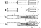
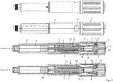
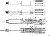
- the first embodiment of the FIGS. 1 to 6 and the second embodiment of the FIGS. 7 to 10 differ essentially in the design of a dose indicator element 10 and a slide member 11.
- the dose indicator 10 has an internal thread 10b, which in an external thread 11a of the slide member 11 ( FIG. 1 ) intervenes.
- the second embodiment has a dose indicator element 10 which has an external thread 10b which is inserted into an internal thread 11a of the housing 1 (FIG. FIG. 8 ) intervenes.
- the drive and metering device forms an injection device or is at least part of such an injection device.
- the drive and metering device has a sleeve-shaped housing 1, which has an outer sleeve 1g and an inner sleeve 1h connected thereto and arranged concentrically therewith.
- the inner sleeve 1h and the outer sleeve 1g are firmly connected via an annular web.
- the housing 1, in particular the inner sleeve 1h has an internal thread 1a, which engages in an external thread 3c of the threaded rod 3a, so that the threaded rod 3a and thus the driven member 3, screwed relative to the housing 1 and along the longitudinal axis L in the distal direction can be.
- the output member 3 has the threaded rod 3a and a plate-shaped flange 3b, which is freely rotatably attached to the distal end of the threaded rod 3a, in particular snapped.
- the threaded rod 3a has at least one guide groove 3d, which superimposes the external thread 3c and extends parallel to the longitudinal axis L.
- a sleeve-shaped rotary member 7 has at its inner circumference at least one web-shaped engaging member 7b, which engages in the guide groove 3d, whereby the rotary member 7 and the driven member 3 relative to each other are rotationally and axially displaceable.
- the rotary member 7 has on its outer circumference an annular groove 7d, into which a projection 1f formed on the inner circumference of the housing 1, in particular of the inner sleeve 1h engages, whereby the rotary member 7 is rotatable and axially fixed relative to the housing 1.
- Rotation of the rotary member 7 causes rotation of the driven member 3, whereby the driven member 3 is movable along the longitudinal axis L due to the threaded engagement with the housing 1.
- the output member 3 is moved in the distal direction when the rotary member 7 is rotated relative to the housing 1 in a second rotational direction about the longitudinal axis L.
- the rotary member 7 has a second coupling structure 7a in the form of an external toothing.
- the housing 1, in particular the inner sleeve 1h, has an engagement structure on its outer circumference, this engagement structure and a groove or rib-shaped longitudinal guide 11e formed on the inner circumference of the sliding member 11 meshing in such a way that the displacement member 11 is secured against rotation relative to the housing 1 about the longitudinal axis L. along the longitudinal axis L is displaceable.
- the displacement member 11 has on its inner circumference an internal toothing 11f, in which a locking means 7c, which is resiliently formed on the rotary member 7, engages.
- the latching means 7c has a latching arm, on the outside of which an engagement cam is arranged, which engages in the internal toothing 11f.
- the locking means 7c slides over the internal toothing 11f, whereby the product distribution can be signaled, for example, by means of an acoustic and / or tactile signal.
- the engagement of the locking means 7c in the internal toothing 11f may be in a variant such that the rotary member 7 can be rotated relative to the housing 1 or the displacement member 11 only after overcoming a certain limit torque.
- the engagement of the locking means 7c in the internal toothing 11f prevents the driven member 3 from unintentionally rotating relative to the housing 1, such as by vibrations during the transport of the drive and metering device.
- the limit torque is designed so that it can be easily overcome by a torque which is provided by a rotationally biased drive spring 5 during the product distribution.
- the locking means 7c serve the internal toothing 11f only for generating an acoustic and / or tactile signal during product distribution.
- the internal toothing 11f forms a seventh coupling structure, which engages in the external toothing of the second coupling structure 7a.
- the second clutch structure 7a and the seventh clutch structure 11f form a fourth clutch 7a, 11f.
- the rotary member 7 may have an eighth coupling structure in the form of a toothing, in particular external toothing, which is separate from the second coupling structure 7a, for example.
- the seventh coupling structure 11f and the eighth coupling structure may form the fourth coupling.
- the fourth clutch 7a, 11f is engaged when the actuator 8 is inoperative and disengaged when the actuator 8 is operated.
- the fourth clutch 7a, 11f is engaged, the seventh clutch structure 11f and the second clutch structure 7a or the eighth clutch structure are rotationally engaged with each other.
- the sliding member 11 has at its proximal end an annular groove 11d, in which a projection 4g engages the inner periphery of a drive member 4, whereby the drive member 4 is rotatable relative to the shift member 11 and axially fixed.
- a displacement of the drive member 4 along the longitudinal axis L thus also causes a displacement of the slide member 11 along the longitudinal axis L.
- the drive member 4 has a first coupling structure 4a in the form of an internal toothing, which forms a first coupling 4a, 7a with the second coupling structure 7a.
- the drive member 4 is displaceable from a disengaged position, in which the first coupling structure 4a and the second coupling structure 7a do not mesh, into an engaged position along the longitudinal axis L, in which the first coupling structure 4a and the second coupling structure 7a engage in a form-fitting manner.
- the drive member 4 is rotatable relative to the rotary member 7 about the longitudinal axis L when the first clutch 4a, 7a is disengaged, and relative to the rotary member 7 rotationally about the longitudinal axis L when the first clutch 4a, 7a is engaged.
- the drive member 4 has a latching structure 4d, which is resiliently formed on the drive member 4.
- the latching structure 4d has at least one tooth, which is in engagement with a toothing, in particular the second coupling structure 7a of the rotary member 7, when the first clutch 4a, 7a is disengaged.
- the latching structure 4d snaps over the toothing, in particular the second coupling structure 7a of the rotary member 7, when the drive member 4 is rotated relative to the rotary member 7 during the setting of a dispensed product dose in a first rotational direction and / or a second rotational direction.
- click noises are generated, which tactile and / or audible signal the user setting the dose and on the other hand given discrete angular positions for the drive member 4 with respect to the rotary member 7.
- the engagement of the latching structure 4d in the rotary member 7 with respect to the engagement of the latching means 7c in the internal teeth 11f be designed so that upon rotation of the drive member 4 relative to the rotary member 7 thereby the torque applied to the rotary member 7 is less than the limit torque necessary for rotation of the rotary member 7 with respect to the slide member 11.
- the drive member 4 has a fourth coupling structure 4b, which is designed as external teeth.
- the fourth coupling structure 4b forms a second coupling 2b, 4b with a third coupling structure 2b, which is configured as internal toothing.
- Attached to the housing 1 is a sleeve-shaped dose setting member 2, wherein the dose setting member 2 is rotatable and axially fixed relative to the housing 1.
- the dose setting member 2 has an outer sleeve and an inner sleeve, which are fixedly connected to one another via a web.
- the dosage setting member 2 in particular the outer sleeve, has on its inner circumference a projection 2a, which engages in an annular groove of the housing 1, in particular the outer sleeve 1g, so that the dose setting member 2 is rotatable and axially fixed relative to the housing 1.
- the dosage setting member 2 in particular its inner sleeve, forms the third coupling structure 2b.
- the third coupling structure 2b engages positively in the fourth coupling structure 4b, when the second clutch 2b, 4b is engaged, whereby the dose setting member 2 is non-rotatably connected to the drive member 4 about the longitudinal axis L.
- the drive member 4 thus makes rotational movements of the dose setting member 2.
- the second clutch 2b, 4b is disengaged, the third clutch structure 2b and the fourth clutch structure 4b do not mesh with each other, so that the dose setting member 2 and the drive member 4 are rotatable relative to each other.
- the dose setting member 2 is rotated relative to the housing 1 to increase the dose in a first direction of rotation and to reduce the correction of the dose in a second direction of rotation.
- the second clutch 2b, 4b is engaged, whereby the drive member 4 participates in the rotational movements of the dose setting member 2.
- the dosage setting member 2 is arranged at the proximal end of the housing 1 and is graspable by the user of the device and rotatable relative to the housing 1.
- the proximal end of the drive and metering device is formed by an actuator 8, which is designed as an actuating button.
- the actuator 8 may be from an unactuated position (see for example Figures 3 and 9 ) in an actuated position (see for example Figures 5 un 10) are moved against the reset spring 9, thereby the reset spring 9 is tensioned.
- the reset spring 9 is a helical or helical spring, which acts as a compression spring and is supported with its distal end on the dose setting member 2 and with its proximal end on the actuating member 8.
- the actuator 8 for example, with the finger of the thumb of the hand, which surrounds the housing 1, pressed, whereby the spring 9 is tensioned.
- the biased spring 9 of the actuator 8 can slide back from the actuated position to the unactuated position.
- the actuator 8 is reciprocable relative to the dosage setting member 2 along the longitudinal axis L, namely between the actuated position and the unactuated position.
- the actuator 8 is designed in several parts and has a connecting member 8a, which has a sleeve-shaped portion which is narrowed or closed at the distal end by an inwardly projecting collar.
- the proximal end of the connecting member 8a is closed by means of a cover cap 8b, which also belongs to the actuating member 8a and forms a bearing surface for the thumb for actuating the actuating member 8.
- the actuator 8, in particular the sleeve-shaped portion of the connecting member 8a surrounds the drive spring 5 circumferentially.
- the drive spring 5 is a helically wound from a band-shaped material spring, which can also be referred to as a clock spring.
- a first section, in particular a first end of the drive spring 5, is fastened to the actuating member 8, in particular to its cylindrical section.
- a second section, in particular a second end of the drive spring 5, is fastened to the drive element 4, in particular between its proximal end 4c and a collar 4e.
- the drive spring 5 has a third section, which is elastically deformed when the spring tension changes.
- a rotation of the drive member 4 relative to the actuator 8 causes a change in the spring tension, in particular a decrease in the spring tension while delivering the potential energy stored by the spring 5 to the drive member 4 in the form of kinetic, d. H. Rotational energy.
- the drive member 4 has a particular rod or pin-shaped portion which extends through the collar at the distal end of the actuator 8 in the interior of the actuator 8 and by the drive spring 5.
- the proximal end 4c tapers towards the proximal end of the drive and metering device, for example spherical, conical or frusto-conical.
- the actuating member 8, in particular the covering cap 8e forms a contact surface 8d for the proximal end 4c of the drive member 4.
- the actuating member 8, in particular the connecting member 8a, has a sixth coupling structure 8c in the form of an outer toothing, which is formed, for example, on a projection projecting in the distal direction.
- the Abragung engages through the collar which connects the inner sleeve with the outer sleeve of the dose setting 2.
- the housing 1, in particular the outer sleeve 1g, has a fifth coupling structure 1c, which is formed as an internal toothing and forms a third coupling 1c, 8c with the sixth coupling structure 8c.
- the sixth clutch structure 8c engages positively in the fifth clutch structure 1c, as a result of which the actuating member 8 and in particular also the dose setting member 2 connected in a rotationally fixed manner to the actuating member 8 is rotationally fixed with respect to the housing 1.
- the actuator 8 and the dose setting member 2 are rotatable relative to the housing 1 when the third clutch 1c, 8c is disengaged, and the sixth clutch structure 8c and the fifth clutch structure 1c are then disengaged.
- a sleeve-shaped product container holder in particular permanently attached, in which a product container 6 is received.
- the product container 6 is a carpule in the example shown.
- the product container 6 has a container body 6a surrounding a liquid product to be administered, wherein in the container body 6a proximal to the product, a displaceable piston 6b is arranged, which bears sealingly against the inner wall of the container body 6.
- a septum 6c is formed, which can be pierced by means of a needle, which is attachable to a thread 12c of the product container holder 12. to Displacement of the piston 6b in the direction of the septum 6c, the product contained in the product container 6 is discharged via the needle.
- the product container holder 12 has a window 12d, by means of which the amount of product contained in the product container 6 can be optically monitored.
- the product container holder 12 has a recess 12 b into which a first engagement structure 1 b is snapped on the inner circumference of the housing 1, in particular the outer sleeve 1, when the product container holder 12 is attached to the housing 1.
- the product container holder 12 has an annular circumferential collar 12a on its outer circumference, which rests against the distal end of the housing 1, in particular the outer sleeve 1g, when the product container holder 12 is fastened to the housing 1.
- the product container holder 12 has on its outer circumference a cam 12e, with which a sleeve-shaped cap, which is slidable over the product container holder 12, is releasably 29nappbar.
- the cap 14 can thus be removed again and serves only to protect an optionally attached needle and / or the drug from exposure to light.
- the cap 14 has a ring on the inner circumference mounted recess 14a, in particular groove.
- the drive and metering device has a dose limiter 13 in the form of a ring segment, alternatively a ring or a nut, which has on its inner circumference a threaded portion 13b which engages in a arranged on the outer circumference of the housing 1 thread 1e, so that the dose limiter 13th can be screwed relative to the housing 4.
- the dose limiter 13 is accommodated in a groove 2c arranged on the inner circumference of the dosage setting member 2 and extending along the longitudinal axis L, the groove flanks enclosing the ring segment-shaped dose limiter 13 laterally.
- the dose limiter 13 On the outer circumference, the dose limiter 13 has a groove-shaped engagement member 13a, in which a longitudinal guide, which protrudes from the groove bottom of the groove 2c of the dose setting member 2 and extends along the longitudinal axis L, engages. Both through the groove 2c and through the longitudinal guide of the dose limiter 13 is rotatably relative to the dose setting 2, but axially displaceable. At the dose setting member 2 or the housing 1, a stop stop is formed, of which the dose limiter 13 is spaced in proportion to the maximum amount of product to be distributed from the product container 6.
- the dose limiter 13 Since, at the dose setting, the dosage setting member 2 is rotated relative to the housing 4 and at a dose distribution is not rotated, a count can be formed by the dose limiter 13, which adds the already distributed individual doses and the currently set dose and accordingly approaches closer and closer to the stop stop of the dose setting 2 or the housing 1.
- a dose increase causes the dose limiter 13 to move toward the stop stop.
- Dose reduction causes the dose limiter 13 to be moved away from the stop stop.
- the dose limiter 13 comes into contact with the stop stop, so that a rotation of the dose setting 2 relative to the housing 1 in a rotational direction, the one Increasing the dose would result, ie in a first direction of rotation, is blocked.
- the dose indicator element 10 which is sleeve-shaped and thus can be called a dose indicating drum, has over its outer periphery a helical extending dose scale 10b corresponding to the pitch of the thread 10e, comprising a plurality of successively arranged scale values.
- the drive and metering device can be used to set a maximum dose of 80 IU, with the scale from 0 to 80 and the dose values in two steps.
- the dose indicator 10 has a circumferentially facing and acting stop surface, referred to as the zero dose stop 10e.
- the dose indicator has a circumferentially facing and acting stop surface, referred to as the maximum dose stop 10d.
- the sleeve-shaped displacement member 11 has an external thread 11a in which the internal thread 10b engages.
- the shift member 11 further includes a zero dose counter stop 11b and a maximum dose counter stop 11c.
- the thread 10b is an external thread which is in engagement with an internal thread 11a of the outer sleeve 1g of the housing 1, or generally the housing 1.
- the housing 1, in particular the outer sleeve 1g, has a zero dose counter stop 11b and a maximum dose counter stop 11c.
- the dose indicator element 10 can be screwed back and forth between a zero dose position and a maximum dose position.
- the zero dose stop 10e in cooperation with the zero dose counter stop 11b, prevents rotation of the dose indicating element 10 in a second rotational direction, namely in a rotational direction that would cause a dose smaller than zero to be set.
- the dose indicator 10 In this zero dose position, the dose indicator 10 is in the opposite, d. H. rotatable first direction of rotation.
- the maximum dose stop 10d In the maximum dose position, the maximum dose stop 10d, in cooperation with the maximum dose counteracting stop 11c, prevents rotation of the dose indicating element 10 in the first direction of rotation, which would cause the dose to be increased beyond the maximum adjustable value.
- the rotation in the second direction of rotation is possible in the maximum dose position.
- the housing 1, in particular the outer sleeve 1g, has a pointing device 1d in the form of a window which exposes the dose scale 10a of the dose indicator element 10.
- the dose indicator 10 is rotatably connected to the drive member 4 and axially displaceably connected.
- the dose indicator element 10 at least one, in this example, a plurality of guide grooves 10c, which extend parallel to the longitudinal axis L. In these guide grooves 10c engage projections 4f on the outer circumference of the drive member 4 a.
- the first and second embodiments are shown in their delivery or initial state with the cap 14 removed.
- the actuator 8 is not actuated.
- the dose appears zero, that is, the dose indicating element 10 is in its zero dose position.
- the drive spring 5 is biased with so much energy that the amount of product contained in the product container 6 can be completely released with the energy stored in the spring 5 by moving the piston 6b, in particular in one or more individual distributions, between each of which a new dose setting takes place without tensioning the spring 5.
- the first clutch 4a, 7a are disengaged, the second clutch 2b, 4b engaged and the third clutch 1c, 8c disengaged.
- the drive spring 5 is kinematically connected between the drive member 4 and the dose setting member 2.
- the clutch 2b, 4b prevents the drive member 4 from being rotated relative to the dose setting member 2.
- the dosage setting member 2 is rotated relative to the housing 1 in a first rotational direction, whereby the drive member 4, the spring 5 and the dose indicator 10 are also rotated.
- the rotation causes the dose indicator element 10 to be unscrewed from the zero dose counter-stop 11b, with the distance measured between the zero-dose stop 10e and the zero-dose counter-abutment 11b along the screwing curve being proportional to the product dose to be dispensed.
- the pointing device 1d the currently set dose can be read in IU.
- the dose setting member 2 can be rotated by rotating in the opposite direction of rotation, i. H. are rotated in the second direction of rotation relative to the housing 1, whereby the distance between the zero dose stop and the maximum dose stop decreases and the readable dose is reduced.
- the actuator 8 is moved, for example, with the thumb of the hand, which surrounds the housing 1, from an unactuated position (for example FIGS. 4 and 9 ) in an actuated position (for example Figures 5 and 10 ), whereby the reset spring 9 is tensioned.
- the third clutch 1c, 8c is first engaged, so that the drive spring 5 is kinematically connected between the housing 1 and the drive member 4.
- the dose setting member 2 is then also secured against rotation with respect to the housing 1.
- the dose indicator 10 is simultaneously screwed back to its zero dose position.
- the zero dose stop 10e abuts against the zero dose counter stop 11b, the set dose is completely released, stopping the zero dose stopper 10e at the zero dose counter stop 11b to stop the dose indicating element 10 from rotating, thereby also stopping the drive member 4 from rotating in the second rotational direction becomes.
- This situation is for example in FIG. 5 shown.
- the reset spring 9 returns the actuator 8 to its unactuated position with the first clutch 4a, 7a, the second clutch 2b, 4b, the third clutch 1c, 8c, and the fourth clutch 7a, 11f be returned to their original position.
- a dose to be distributed By rotating the dose setting member 2 in the first direction of rotation can now be set again a dose to be distributed, which can be distributed by actuation of the actuator 8, etc.
- a product amount which is less than the maximum with the device divisible dose in this example less than 80 IU, suggests the dose limiter 13 at its end stop when the dose setting member 2 is rotated in the first direction of rotation before the maximum dose stop 10d abuts on the maximum dose counteracting stop 11c. This prevents the user of the device from being able to inject less product than he has set with the device.
Landscapes
- Health & Medical Sciences (AREA)
- Vascular Medicine (AREA)
- Engineering & Computer Science (AREA)
- Anesthesiology (AREA)
- Biomedical Technology (AREA)
- Heart & Thoracic Surgery (AREA)
- Hematology (AREA)
- Life Sciences & Earth Sciences (AREA)
- Animal Behavior & Ethology (AREA)
- General Health & Medical Sciences (AREA)
- Public Health (AREA)
- Veterinary Medicine (AREA)
- Infusion, Injection, And Reservoir Apparatuses (AREA)
Claims (14)
- Dispositif d'entraînement et de dosage pour un dispositif d'injection servant à distribuer un produit liquide, le dispositif d'entraînement et de dosage comprenant :a) un boîtier (1),b) un organe de réglage de dose (2), lequel peut tourner par rapport au boîtier (1) pour le réglage d'une dose de produit à distribuer,c) un organe de sortie (3) logé dans le boîtier (1),d) un organe d'entraînement (4), qui peut tourner par rapport au boîtier (1) et est couplé à l'organe de sortie (3) pendant la distribution de produit de telle sorte qu'une rotation de l'organe d'entraînement (4) a pour effet que l'organe de sortie (3) est déplacé dans la direction distale par rapport au boîtier (1),
caractérisé en ce que le dispositif d'entraînement et de dosage comprend par ailleurse) un ressort d'entraînement (5) précontraint, qui est connecté pendant le réglage de la dose de produit entre l'organe de réglage de dose (2) et l'organe d'entraînement (4), l'organe de réglage de dose (2) étant couplé de manière solidaire en rotation à l'organe d'entraînement (4) pendant le réglage de la dose de produit de sorte qu'une rotation de l'organe d'entraînement (4) par rapport à l'organe de réglage de dose (2) soit empêchée,f) dans lequel l'organe de réglage de dose (2) est solidaire en rotation par rapport au boîtier (1) pendant la distribution de produit. - Dispositif d'entraînement et de dosage selon la revendication 1, caractérisé en ce que le ressort d'entraînement (5) est précontraint si fortement que l'énergie de ressort stockée dans le ressort d'entraînement (5) suffit pour réaliser une distribution en totalité du produit contenu dans un contenant de produit (6) fixé ou pouvant être fixé au niveau du dispositif d'entraînement et de dosage.
- Dispositif d'entraînement et de dosage selon l'une quelconque des revendications précédentes, caractérisé en ce que l'organe de réglage de dose (2) et l'organe d'entraînement (4) peuvent être tournés pendant le réglage de la dose de produit par rapport à l'organe de sortie (3) et/ou au boîtier (1) dans une première direction de rotation, ce qui a pour effet d'augmenter la dose de produit à distribuer, et dans une seconde direction de rotation, ce qui a pour effet de réduire la dose de produit à distribuer.
- Dispositif d'entraînement et de dosage selon l'une quelconque des revendications précédentes, caractérisé en ce qu'un organe de rotation (7) est disposé de manière cinématique entre l'organe d'entraînement (4) et l'organe de sortie (3), dans lequel soit- l'organe de rotation (7) est en prise par filetage avec un filetage (3c) de l'organe de sortie (3) et l'organe de sortie (3) est en prise avec un guidage solidaire du boîtier du dispositif d'entraînement et de dosage de sorte qu'une rotation de l'organe de rotation (7) ait pour effet un déplacement de l'organe de sortie (3) dans la direction distale,
soit- un filetage (la) solidaire du boîtier est en prise par filetage avec un filetage (3c) de l'organe de sortie (3) et l'organe de sortie (3) est en prise avec un guidage (7b) de l'organe de rotation (7) de sorte qu'une rotation de l'organe de rotation (7) ait pour effet un déplacement de vissage de l'organe de sortie (3) dans la direction distale. - Dispositif d'entraînement et de dosage selon l'une quelconque des revendications précédentes, caractérisé en ce qu'une rotation de l'organe d'entraînement (4) par rapport au boîtier (1) et/ou à l'organe de réglage de dose (2) a pour effet que l'organe de sortie (3) est déplacé par rapport au boîtier (1) dans la direction distale.
- Dispositif d'entraînement et de dosage selon l'une quelconque des revendications précédentes, caractérisé par un organe d'actionnement (8), en particulier un bouton d'actionnement formé au niveau de l'extrémité proximale du dispositif d'entraînement et de dosage, lequel peut être coulissé depuis une position non actionnée, qu'il adopte pendant le réglage de la dose de produit à distribuer, dans une position actionnée, qu'il adopte pendant la distribution de produit, dans lequel de préférence un ressort de réinitialisation (9) est prévu, qui agit de telle sorte sur l'organe d'actionnement (8) que le ressort de réinitialisation (9) est tendu quand l'organe d'actionnement (8) est coulissé depuis sa position non actionnée dans sa position actionnée, et en particulier que l'organe d'actionnement (8) peut être coulissé au moyen du ressort de réinitialisation (9) depuis sa position actionnée dans sa position non actionnée.
- Dispositif d'entraînement et de dosage selon l'une quelconque des revendications précédentes, caractérisé par un premier couplage (4a, 7a), qui est disposé entre l'organe d'entraînement (4) et l'organe de sortie (3), dans lequel le premier couplage (4a, 7a) est désaccouplé pendant le réglage de la dose de produit et permet ainsi à l'organe d'entraînement (4) d'être tourné par rapport à l'organe de sortie (3), et est accouplé pendant la distribution de produit.
- Dispositif d'entraînement et de dosage selon l'une quelconque des revendications précédentes, caractérisé par un deuxième couplage (2b, 4b), qui est disposé entre l'organe de réglage de dose (2) et l'organe d'entraînement (4), dans lequel le deuxième couplage (2b, 4b) est accouplé pendant le réglage de la dose de produit, ce qui permet de bloquer en rotation l'organe de réglage de dose (2) et l'organe d'entraînement (4), et est désaccouplé pendant la distribution de produit, ce qui permet de faire tourner l'organe d'entraînement (4) au moyen du ressort d'entraînement (5) précontraint par rapport à l'organe de réglage de dose (2).
- Dispositif d'entraînement et de dosage selon l'une quelconque des revendications précédentes, caractérisé par un troisième couplage (1c, 8c), qui est disposé entre l'organe de réglage de dose (2) et le boîtier (1), dans lequel le troisième couplage (1c, 8c) est désaccouplé pendant le réglage de la dose de produit, ce qui permet de faire tourner l'organe de réglage de dose (2) par rapport au boîtier (1), et est accouplé pendant la distribution de produit, ce qui permet de rendre solidaire en rotation l'organe de réglage de dose (2) par rapport au boîtier (1).
- Dispositif d'entraînement et de dosage selon la revendication précédentes, caractérisé en ce que le troisième couplage (1c, 8c) est formé entre l'organe d'actionnement (8) et le boîtier (1), dans lequel l'organe d'actionnement (8) et l'organe de réglage de dose (2) sont reliés de manière solidaire en rotation, en particulier pendant le réglage de la dose de produit et pendant la distribution de produit.
- Dispositif d'entraînement et de dosage selon l'une quelconque des revendications précédentes, caractérisé en ce que le ressort d'entraînement (5) présente une première section, par laquelle le ressort d'entraînement (5) prend appui de manière solidaire en rotation pendant le réglage de la dose de produit par rapport à l'organe de réglage de dose (2) ou pendant la distribution de produit par rapport au boîtier (1), une deuxième section, par laquelle le ressort d'entraînement (5) prend appui de manière solidaire en rotation par rapport à l'organe d'entraînement (4), et une troisième section, qui est disposée entre la première section et la deuxième section et qui se déforme de manière élastique dans le cas d'une modification de la tension de ressort du ressort d'entraînement (5), dans lequel de préférence la première section et la deuxième section sont contraintes en torsion par rapport au boîtier (1) et en particulier sont à l'arrêt quand l'organe de réglage de dose (2) est tourné pour le réglage de dose.
- Dispositif d'entraînement et de dosage selon l'une quelconque des revendications précédentes, caractérisé par un élément d'affichage de dose (10), qui présente au niveau de sa périphérie extérieure une graduation de dose (10a) et qui est relié de manière solidaire en rotation à l'organe d'entraînement (4) de sorte que l'élément d'affichage de dose (10) accompagne les déplacements de rotation de l'organe d'entraînement (4), dans lequel le boîtier (1) présente un système indicateur (1d), en particulier une fenêtre, par lequel une valeur d'échelle de la graduation de dose (10a), qui correspond à la dose réglée, peut être lue.
- Dispositif d'entraînement et de dosage selon l'une quelconque des revendications précédentes, caractérisé en ce que le ressort d'entraînement (5) est logé dans l'organe d'actionnement (8) et repose par une première section au niveau de l'organe d'actionnement (8) et est soutenu ce faisant indirectement au niveau de l'organe de réglage de dose (2) et/ou du boîtier (1).
- Dispositif d'entraînement et de dosage selon l'une quelconque des revendications précédentes, caractérisé en ce qu'est disposé entre l'organe d'entraînement (4) et l'organe d'actionnement (8) un système (4c, 8d), lequel réduit en particulier le frottement entre l'organe d'actionnement (8) et l'organe d'entraînement (4) quand l'organe d'entraînement (4) tourne par rapport à l'organe d'actionnement (8) pendant la distribution de produit, dans lequel le système (4c, 8d) est de préférence tel que l'extrémité proximale (4c) de l'organe d'entraînement (4) se rétrécit en direction d'une surface de contact (8d) de l'organe d'actionnement (8), dans lequel une fente existe entre l'extrémité proximale (4c) de l'organe d'entraînement (4) et la surface de contact (8d) quand l'organe d'actionnement (8) est dans sa position non actionnée, et l'extrémité proximale (4c) de l'organe d'entraînement (4) repose au niveau de la surface de contact (8d) quand l'organe d'actionnement (8) est dans sa position actionnée.
Priority Applications (4)
| Application Number | Priority Date | Filing Date | Title |
|---|---|---|---|
| EP13195948.8A EP2881131B1 (fr) | 2013-12-05 | 2013-12-05 | Dispositif d'entraînement et de dosage pour un dispositif d'injection doté d'un ressort d'entraînement précontraint |
| PCT/CH2014/000161 WO2015081451A1 (fr) | 2013-12-05 | 2014-11-06 | Dispositif de dosage et d'entraînement pour un dispositif d'injection à ressort d'entraînement précontraint |
| CN201480065899.3A CN106029130B (zh) | 2013-12-05 | 2014-11-06 | 用于注射装置的带有预紧的驱动弹簧的驱动和配量装置 |
| US15/173,321 US10603443B2 (en) | 2013-12-05 | 2016-06-03 | Driving and dosing device for an injection device with a pretensioned driving spring |
Applications Claiming Priority (1)
| Application Number | Priority Date | Filing Date | Title |
|---|---|---|---|
| EP13195948.8A EP2881131B1 (fr) | 2013-12-05 | 2013-12-05 | Dispositif d'entraînement et de dosage pour un dispositif d'injection doté d'un ressort d'entraînement précontraint |
Publications (2)
| Publication Number | Publication Date |
|---|---|
| EP2881131A1 EP2881131A1 (fr) | 2015-06-10 |
| EP2881131B1 true EP2881131B1 (fr) | 2019-04-24 |
Family
ID=49725048
Family Applications (1)
| Application Number | Title | Priority Date | Filing Date |
|---|---|---|---|
| EP13195948.8A Active EP2881131B1 (fr) | 2013-12-05 | 2013-12-05 | Dispositif d'entraînement et de dosage pour un dispositif d'injection doté d'un ressort d'entraînement précontraint |
Country Status (4)
| Country | Link |
|---|---|
| US (1) | US10603443B2 (fr) |
| EP (1) | EP2881131B1 (fr) |
| CN (1) | CN106029130B (fr) |
| WO (1) | WO2015081451A1 (fr) |
Families Citing this family (9)
| Publication number | Priority date | Publication date | Assignee | Title |
|---|---|---|---|---|
| CH711240A2 (de) * | 2015-06-23 | 2016-12-30 | Tecpharma Licensing Ag | Autoinjektionsvorrichtung. |
| CH711344A2 (de) | 2015-07-21 | 2017-01-31 | Tecpharma Licensing Ag | Injektionsvorrichtung. |
| AR106692A1 (es) * | 2015-11-16 | 2018-02-07 | Sanofi Sa | Dispositivo de administración de fármaco |
| CH712146A2 (de) | 2016-02-23 | 2017-08-31 | Tecpharma Licensing Ag | Injektionsvorrichtung mit einem distal eines Dosiseinstellglieds angebrachten Betätigungsglied zur Auslösung der Produktausschüttung. |
| US10549044B2 (en) | 2016-06-09 | 2020-02-04 | Becton, Dickinson And Company | Spacer assembly for drug delivery system |
| US10792432B2 (en) | 2016-06-09 | 2020-10-06 | Becton, Dickinson And Company | Drive assembly and spacer for drug delivery system |
| US10773024B2 (en) * | 2016-06-09 | 2020-09-15 | Becton, Dickinson And Company | Drive assembly for drug delivery system |
| US10751476B2 (en) | 2016-06-09 | 2020-08-25 | Becton, Dickinson And Company | Actuator assembly for drug delivery system |
| JP1749404S (ja) * | 2021-09-30 | 2023-07-27 | 計量器 |
Family Cites Families (12)
| Publication number | Priority date | Publication date | Assignee | Title |
|---|---|---|---|---|
| GB8809115D0 (en) | 1988-04-18 | 1988-05-18 | Turner R C | Syringes |
| US6663602B2 (en) * | 2000-06-16 | 2003-12-16 | Novo Nordisk A/S | Injection device |
| WO2008031235A1 (fr) | 2006-09-15 | 2008-03-20 | Tecpharma Licensing Ag | Appareil d'injection à entraînement à faibles pertes |
| WO2008037801A1 (fr) * | 2006-09-29 | 2008-04-03 | Novo Nordisk A/S | Dispositif d'injection comportant un moyen de détection électronique |
| DE102007026083A1 (de) * | 2007-05-25 | 2008-11-27 | Haselmeier S.A.R.L. | Injektionsgerät |
| CN101925374B (zh) * | 2008-01-23 | 2014-11-26 | 诺沃-诺迪斯克有限公司 | 用于注射所分配剂量的液体药物的设备 |
| DE102008011886A1 (de) * | 2008-02-29 | 2009-09-24 | Tecpharma Licensing Ag | Injektionsvorrichtung mit einer Einrichtung zur Verhinderung von Fehlausschüttungen |
| AT506690B1 (de) * | 2008-06-16 | 2009-11-15 | Pharma Consult Ges M B H & Co | Injektionsvorrichtung |
| CH700643A1 (de) * | 2009-03-20 | 2010-09-30 | Tecpharma Licensing Ag | Verabreichungsvorrichtung mit auswechselbarer Produkteinheit. |
| PL214940B1 (pl) * | 2009-07-31 | 2013-09-30 | Lozano Platonoff Alberto | Mechanizm wskaznikowy automatycznego aplikatora, zwlaszcza do insuliny |
| PL220720B1 (pl) * | 2012-02-08 | 2015-12-31 | Copernicus Spółka Z Ograniczoną Odpowiedzialnością | Urządzenie wstrzykujące z mechanizmem resetu dawki |
| EP2644217A1 (fr) | 2012-03-30 | 2013-10-02 | TecPharma Licensing AG | Dispositif d'injection avec affichage de dose et entraînement par ressort |
-
2013
- 2013-12-05 EP EP13195948.8A patent/EP2881131B1/fr active Active
-
2014
- 2014-11-06 WO PCT/CH2014/000161 patent/WO2015081451A1/fr not_active Ceased
- 2014-11-06 CN CN201480065899.3A patent/CN106029130B/zh active Active
-
2016
- 2016-06-03 US US15/173,321 patent/US10603443B2/en active Active
Non-Patent Citations (1)
| Title |
|---|
| None * |
Also Published As
| Publication number | Publication date |
|---|---|
| US20160279340A1 (en) | 2016-09-29 |
| US10603443B2 (en) | 2020-03-31 |
| CN106029130A (zh) | 2016-10-12 |
| WO2015081451A1 (fr) | 2015-06-11 |
| CN106029130B (zh) | 2020-05-29 |
| EP2881131A1 (fr) | 2015-06-10 |
Similar Documents
| Publication | Publication Date | Title |
|---|---|---|
| EP2881131B1 (fr) | Dispositif d'entraînement et de dosage pour un dispositif d'injection doté d'un ressort d'entraînement précontraint | |
| EP2829292B1 (fr) | Dispositif d'entraînement et de dosage comprenant un élément de limitation pour empêcher le réglage d'une dose plus grande que disponible | |
| DE102005008280B3 (de) | Verabreichungsvorrichtung mit Anzeigetrommel | |
| EP1416982B1 (fr) | Dispositif de verrouillage destiné à la connexion de sections de bôitier d'un appareil d'administration | |
| EP3590569B1 (fr) | Dispositif d'administration dosée d'un produit fluide pouvant être séparé pour le changement de récipient | |
| EP2830684B1 (fr) | Dispositif d'injection avec affichage de dose et entraînement par ressort | |
| EP2830685B1 (fr) | Dispositif d'injection avec élément d'affichage de dose déplacable relatif à un boitier. | |
| EP2644218B1 (fr) | Dispositif d'injection avec affichage de dose et entraînement par ressort | |
| EP2918298B1 (fr) | Mécanisme de dosage amélioré pour un dispositif d'injection pour l'administration d'un produit | |
| EP2692377B1 (fr) | Dispositif d'injection avec élément d'affichage de dose pour signaler fin d'injection | |
| EP3043840B1 (fr) | Dispositif d'injection comportant un bouton d'actionnement dont l'actionnement provoque un mouvement de rotation | |
| EP1965845A1 (fr) | Dispositif d'injection doté d'un organe de dosage ou d'affichage a superposition axiale | |
| EP3938014B1 (fr) | Dispositif de dosage pour un dispositif d'injection | |
| EP2881132B1 (fr) | Dispositif d'injection doté d'un organe de dosage et d'un ressort de versement précontraint | |
| EP2692376B1 (fr) | Dispositif d'injection avec échelle de dosage en forme d'hélice ou de spirale | |
| CH709878A2 (de) | Antriebs- und Dosiervorrichtung mit einem Begrenzungselement zur Verhinderung der Einstellung einer Dosis. | |
| EP3419702B1 (fr) | Appareil d'injection avec élément d'actionnement disposé latéralement pour déclencher l'administration d'un produit |
Legal Events
| Date | Code | Title | Description |
|---|---|---|---|
| PUAI | Public reference made under article 153(3) epc to a published international application that has entered the european phase |
Free format text: ORIGINAL CODE: 0009012 |
|
| 17P | Request for examination filed |
Effective date: 20131205 |
|
| AK | Designated contracting states |
Kind code of ref document: A1 Designated state(s): AL AT BE BG CH CY CZ DE DK EE ES FI FR GB GR HR HU IE IS IT LI LT LU LV MC MK MT NL NO PL PT RO RS SE SI SK SM TR |
|
| AX | Request for extension of the european patent |
Extension state: BA ME |
|
| R17P | Request for examination filed (corrected) |
Effective date: 20151117 |
|
| GRAP | Despatch of communication of intention to grant a patent |
Free format text: ORIGINAL CODE: EPIDOSNIGR1 |
|
| STAA | Information on the status of an ep patent application or granted ep patent |
Free format text: STATUS: GRANT OF PATENT IS INTENDED |
|
| INTG | Intention to grant announced |
Effective date: 20180712 |
|
| GRAJ | Information related to disapproval of communication of intention to grant by the applicant or resumption of examination proceedings by the epo deleted |
Free format text: ORIGINAL CODE: EPIDOSDIGR1 |
|
| STAA | Information on the status of an ep patent application or granted ep patent |
Free format text: STATUS: REQUEST FOR EXAMINATION WAS MADE |
|
| GRAP | Despatch of communication of intention to grant a patent |
Free format text: ORIGINAL CODE: EPIDOSNIGR1 |
|
| STAA | Information on the status of an ep patent application or granted ep patent |
Free format text: STATUS: GRANT OF PATENT IS INTENDED |
|
| INTC | Intention to grant announced (deleted) | ||
| INTG | Intention to grant announced |
Effective date: 20181221 |
|
| GRAS | Grant fee paid |
Free format text: ORIGINAL CODE: EPIDOSNIGR3 |
|
| GRAJ | Information related to disapproval of communication of intention to grant by the applicant or resumption of examination proceedings by the epo deleted |
Free format text: ORIGINAL CODE: EPIDOSDIGR1 |
|
| GRAL | Information related to payment of fee for publishing/printing deleted |
Free format text: ORIGINAL CODE: EPIDOSDIGR3 |
|
| STAA | Information on the status of an ep patent application or granted ep patent |
Free format text: STATUS: REQUEST FOR EXAMINATION WAS MADE |
|
| GRAR | Information related to intention to grant a patent recorded |
Free format text: ORIGINAL CODE: EPIDOSNIGR71 |
|
| STAA | Information on the status of an ep patent application or granted ep patent |
Free format text: STATUS: GRANT OF PATENT IS INTENDED |
|
| GRAA | (expected) grant |
Free format text: ORIGINAL CODE: 0009210 |
|
| STAA | Information on the status of an ep patent application or granted ep patent |
Free format text: STATUS: THE PATENT HAS BEEN GRANTED |
|
| INTC | Intention to grant announced (deleted) | ||
| AK | Designated contracting states |
Kind code of ref document: B1 Designated state(s): AL AT BE BG CH CY CZ DE DK EE ES FI FR GB GR HR HU IE IS IT LI LT LU LV MC MK MT NL NO PL PT RO RS SE SI SK SM TR |
|
| INTG | Intention to grant announced |
Effective date: 20190319 |
|
| REG | Reference to a national code |
Ref country code: GB Ref legal event code: FG4D Free format text: NOT ENGLISH |
|
| REG | Reference to a national code |
Ref country code: CH Ref legal event code: EP |
|
| REG | Reference to a national code |
Ref country code: AT Ref legal event code: REF Ref document number: 1123375 Country of ref document: AT Kind code of ref document: T Effective date: 20190515 Ref country code: IE Ref legal event code: FG4D Free format text: LANGUAGE OF EP DOCUMENT: GERMAN |
|
| REG | Reference to a national code |
Ref country code: DE Ref legal event code: R096 Ref document number: 502013012688 Country of ref document: DE |
|
| REG | Reference to a national code |
Ref country code: NL Ref legal event code: MP Effective date: 20190424 |
|
| REG | Reference to a national code |
Ref country code: LT Ref legal event code: MG4D |
|
| PG25 | Lapsed in a contracting state [announced via postgrant information from national office to epo] |
Ref country code: NL Free format text: LAPSE BECAUSE OF FAILURE TO SUBMIT A TRANSLATION OF THE DESCRIPTION OR TO PAY THE FEE WITHIN THE PRESCRIBED TIME-LIMIT Effective date: 20190424 |
|
| PG25 | Lapsed in a contracting state [announced via postgrant information from national office to epo] |
Ref country code: ES Free format text: LAPSE BECAUSE OF FAILURE TO SUBMIT A TRANSLATION OF THE DESCRIPTION OR TO PAY THE FEE WITHIN THE PRESCRIBED TIME-LIMIT Effective date: 20190424 Ref country code: LT Free format text: LAPSE BECAUSE OF FAILURE TO SUBMIT A TRANSLATION OF THE DESCRIPTION OR TO PAY THE FEE WITHIN THE PRESCRIBED TIME-LIMIT Effective date: 20190424 Ref country code: HR Free format text: LAPSE BECAUSE OF FAILURE TO SUBMIT A TRANSLATION OF THE DESCRIPTION OR TO PAY THE FEE WITHIN THE PRESCRIBED TIME-LIMIT Effective date: 20190424 Ref country code: PT Free format text: LAPSE BECAUSE OF FAILURE TO SUBMIT A TRANSLATION OF THE DESCRIPTION OR TO PAY THE FEE WITHIN THE PRESCRIBED TIME-LIMIT Effective date: 20190824 Ref country code: FI Free format text: LAPSE BECAUSE OF FAILURE TO SUBMIT A TRANSLATION OF THE DESCRIPTION OR TO PAY THE FEE WITHIN THE PRESCRIBED TIME-LIMIT Effective date: 20190424 Ref country code: AL Free format text: LAPSE BECAUSE OF FAILURE TO SUBMIT A TRANSLATION OF THE DESCRIPTION OR TO PAY THE FEE WITHIN THE PRESCRIBED TIME-LIMIT Effective date: 20190424 Ref country code: NO Free format text: LAPSE BECAUSE OF FAILURE TO SUBMIT A TRANSLATION OF THE DESCRIPTION OR TO PAY THE FEE WITHIN THE PRESCRIBED TIME-LIMIT Effective date: 20190724 Ref country code: SE Free format text: LAPSE BECAUSE OF FAILURE TO SUBMIT A TRANSLATION OF THE DESCRIPTION OR TO PAY THE FEE WITHIN THE PRESCRIBED TIME-LIMIT Effective date: 20190424 |
|
| PG25 | Lapsed in a contracting state [announced via postgrant information from national office to epo] |
Ref country code: LV Free format text: LAPSE BECAUSE OF FAILURE TO SUBMIT A TRANSLATION OF THE DESCRIPTION OR TO PAY THE FEE WITHIN THE PRESCRIBED TIME-LIMIT Effective date: 20190424 Ref country code: PL Free format text: LAPSE BECAUSE OF FAILURE TO SUBMIT A TRANSLATION OF THE DESCRIPTION OR TO PAY THE FEE WITHIN THE PRESCRIBED TIME-LIMIT Effective date: 20190424 Ref country code: GR Free format text: LAPSE BECAUSE OF FAILURE TO SUBMIT A TRANSLATION OF THE DESCRIPTION OR TO PAY THE FEE WITHIN THE PRESCRIBED TIME-LIMIT Effective date: 20190725 Ref country code: BG Free format text: LAPSE BECAUSE OF FAILURE TO SUBMIT A TRANSLATION OF THE DESCRIPTION OR TO PAY THE FEE WITHIN THE PRESCRIBED TIME-LIMIT Effective date: 20190724 Ref country code: RS Free format text: LAPSE BECAUSE OF FAILURE TO SUBMIT A TRANSLATION OF THE DESCRIPTION OR TO PAY THE FEE WITHIN THE PRESCRIBED TIME-LIMIT Effective date: 20190424 |
|
| PG25 | Lapsed in a contracting state [announced via postgrant information from national office to epo] |
Ref country code: IS Free format text: LAPSE BECAUSE OF FAILURE TO SUBMIT A TRANSLATION OF THE DESCRIPTION OR TO PAY THE FEE WITHIN THE PRESCRIBED TIME-LIMIT Effective date: 20190824 |
|
| REG | Reference to a national code |
Ref country code: DE Ref legal event code: R097 Ref document number: 502013012688 Country of ref document: DE |
|
| PG25 | Lapsed in a contracting state [announced via postgrant information from national office to epo] |
Ref country code: CZ Free format text: LAPSE BECAUSE OF FAILURE TO SUBMIT A TRANSLATION OF THE DESCRIPTION OR TO PAY THE FEE WITHIN THE PRESCRIBED TIME-LIMIT Effective date: 20190424 Ref country code: RO Free format text: LAPSE BECAUSE OF FAILURE TO SUBMIT A TRANSLATION OF THE DESCRIPTION OR TO PAY THE FEE WITHIN THE PRESCRIBED TIME-LIMIT Effective date: 20190424 Ref country code: SK Free format text: LAPSE BECAUSE OF FAILURE TO SUBMIT A TRANSLATION OF THE DESCRIPTION OR TO PAY THE FEE WITHIN THE PRESCRIBED TIME-LIMIT Effective date: 20190424 Ref country code: EE Free format text: LAPSE BECAUSE OF FAILURE TO SUBMIT A TRANSLATION OF THE DESCRIPTION OR TO PAY THE FEE WITHIN THE PRESCRIBED TIME-LIMIT Effective date: 20190424 Ref country code: DK Free format text: LAPSE BECAUSE OF FAILURE TO SUBMIT A TRANSLATION OF THE DESCRIPTION OR TO PAY THE FEE WITHIN THE PRESCRIBED TIME-LIMIT Effective date: 20190424 |
|
| PG25 | Lapsed in a contracting state [announced via postgrant information from national office to epo] |
Ref country code: IT Free format text: LAPSE BECAUSE OF FAILURE TO SUBMIT A TRANSLATION OF THE DESCRIPTION OR TO PAY THE FEE WITHIN THE PRESCRIBED TIME-LIMIT Effective date: 20190424 Ref country code: SM Free format text: LAPSE BECAUSE OF FAILURE TO SUBMIT A TRANSLATION OF THE DESCRIPTION OR TO PAY THE FEE WITHIN THE PRESCRIBED TIME-LIMIT Effective date: 20190424 |
|
| PLBE | No opposition filed within time limit |
Free format text: ORIGINAL CODE: 0009261 |
|
| STAA | Information on the status of an ep patent application or granted ep patent |
Free format text: STATUS: NO OPPOSITION FILED WITHIN TIME LIMIT |
|
| PG25 | Lapsed in a contracting state [announced via postgrant information from national office to epo] |
Ref country code: TR Free format text: LAPSE BECAUSE OF FAILURE TO SUBMIT A TRANSLATION OF THE DESCRIPTION OR TO PAY THE FEE WITHIN THE PRESCRIBED TIME-LIMIT Effective date: 20190424 |
|
| 26N | No opposition filed |
Effective date: 20200127 |
|
| PG25 | Lapsed in a contracting state [announced via postgrant information from national office to epo] |
Ref country code: SI Free format text: LAPSE BECAUSE OF FAILURE TO SUBMIT A TRANSLATION OF THE DESCRIPTION OR TO PAY THE FEE WITHIN THE PRESCRIBED TIME-LIMIT Effective date: 20190424 |
|
| REG | Reference to a national code |
Ref country code: BE Ref legal event code: MM Effective date: 20191231 |
|
| PG25 | Lapsed in a contracting state [announced via postgrant information from national office to epo] |
Ref country code: MC Free format text: LAPSE BECAUSE OF FAILURE TO SUBMIT A TRANSLATION OF THE DESCRIPTION OR TO PAY THE FEE WITHIN THE PRESCRIBED TIME-LIMIT Effective date: 20190424 |
|
| PG25 | Lapsed in a contracting state [announced via postgrant information from national office to epo] |
Ref country code: LU Free format text: LAPSE BECAUSE OF NON-PAYMENT OF DUE FEES Effective date: 20191205 Ref country code: IE Free format text: LAPSE BECAUSE OF NON-PAYMENT OF DUE FEES Effective date: 20191205 |
|
| REG | Reference to a national code |
Ref country code: CH Ref legal event code: PUE Owner name: YPSOMED AG, CH Free format text: FORMER OWNER: TECPHARMA LICENSING AG, CH |
|
| PG25 | Lapsed in a contracting state [announced via postgrant information from national office to epo] |
Ref country code: BE Free format text: LAPSE BECAUSE OF NON-PAYMENT OF DUE FEES Effective date: 20191231 |
|
| REG | Reference to a national code |
Ref country code: DE Ref legal event code: R081 Ref document number: 502013012688 Country of ref document: DE Owner name: YPSOMED AG, CH Free format text: FORMER OWNER: TECPHARMA LICENSING AG, BURGDORF, CH |
|
| REG | Reference to a national code |
Ref country code: AT Ref legal event code: MM01 Ref document number: 1123375 Country of ref document: AT Kind code of ref document: T Effective date: 20191205 |
|
| REG | Reference to a national code |
Ref country code: GB Ref legal event code: 732E Free format text: REGISTERED BETWEEN 20210325 AND 20210331 |
|
| PG25 | Lapsed in a contracting state [announced via postgrant information from national office to epo] |
Ref country code: AT Free format text: LAPSE BECAUSE OF NON-PAYMENT OF DUE FEES Effective date: 20191205 Ref country code: CY Free format text: LAPSE BECAUSE OF FAILURE TO SUBMIT A TRANSLATION OF THE DESCRIPTION OR TO PAY THE FEE WITHIN THE PRESCRIBED TIME-LIMIT Effective date: 20190424 |
|
| PG25 | Lapsed in a contracting state [announced via postgrant information from national office to epo] |
Ref country code: MT Free format text: LAPSE BECAUSE OF FAILURE TO SUBMIT A TRANSLATION OF THE DESCRIPTION OR TO PAY THE FEE WITHIN THE PRESCRIBED TIME-LIMIT Effective date: 20190424 Ref country code: HU Free format text: LAPSE BECAUSE OF FAILURE TO SUBMIT A TRANSLATION OF THE DESCRIPTION OR TO PAY THE FEE WITHIN THE PRESCRIBED TIME-LIMIT; INVALID AB INITIO Effective date: 20131205 |
|
| PG25 | Lapsed in a contracting state [announced via postgrant information from national office to epo] |
Ref country code: MK Free format text: LAPSE BECAUSE OF FAILURE TO SUBMIT A TRANSLATION OF THE DESCRIPTION OR TO PAY THE FEE WITHIN THE PRESCRIBED TIME-LIMIT Effective date: 20190424 |
|
| REG | Reference to a national code |
Ref country code: CH Ref legal event code: U11 Free format text: ST27 STATUS EVENT CODE: U-0-0-U10-U11 (AS PROVIDED BY THE NATIONAL OFFICE) Effective date: 20260101 |
|
| PGFP | Annual fee paid to national office [announced via postgrant information from national office to epo] |
Ref country code: GB Payment date: 20251218 Year of fee payment: 13 |
|
| PGFP | Annual fee paid to national office [announced via postgrant information from national office to epo] |
Ref country code: FR Payment date: 20251217 Year of fee payment: 13 |
|
| PGFP | Annual fee paid to national office [announced via postgrant information from national office to epo] |
Ref country code: DE Payment date: 20251222 Year of fee payment: 13 |
|
| PGFP | Annual fee paid to national office [announced via postgrant information from national office to epo] |
Ref country code: CH Payment date: 20260101 Year of fee payment: 13 |