JP6590693B2 - Pen-type drug injection device and electronic extension monitoring module for monitoring and logging dose setting and administration - Google Patents
Pen-type drug injection device and electronic extension monitoring module for monitoring and logging dose setting and administration Download PDFInfo
- Publication number
- JP6590693B2 JP6590693B2 JP2015525877A JP2015525877A JP6590693B2 JP 6590693 B2 JP6590693 B2 JP 6590693B2 JP 2015525877 A JP2015525877 A JP 2015525877A JP 2015525877 A JP2015525877 A JP 2015525877A JP 6590693 B2 JP6590693 B2 JP 6590693B2
- Authority
- JP
- Japan
- Prior art keywords
- dose
- injection device
- injection
- supplementary
- supplemental
- Prior art date
- Legal status (The legal status is an assumption and is not a legal conclusion. Google has not performed a legal analysis and makes no representation as to the accuracy of the status listed.)
- Active
Links
Images


Classifications
-
- A—HUMAN NECESSITIES
- A61—MEDICAL OR VETERINARY SCIENCE; HYGIENE
- A61M—DEVICES FOR INTRODUCING MEDIA INTO, OR ONTO, THE BODY; DEVICES FOR TRANSDUCING BODY MEDIA OR FOR TAKING MEDIA FROM THE BODY; DEVICES FOR PRODUCING OR ENDING SLEEP OR STUPOR
- A61M5/00—Devices for bringing media into the body in a subcutaneous, intra-vascular or intramuscular way; Accessories therefor, e.g. filling or cleaning devices, arm-rests
- A61M5/178—Syringes
- A61M5/31—Details
- A61M5/315—Pistons; Piston-rods; Guiding, blocking or restricting the movement of the rod or piston; Appliances on the rod for facilitating dosing ; Dosing mechanisms
- A61M5/31525—Dosing
-
- A—HUMAN NECESSITIES
- A61—MEDICAL OR VETERINARY SCIENCE; HYGIENE
- A61M—DEVICES FOR INTRODUCING MEDIA INTO, OR ONTO, THE BODY; DEVICES FOR TRANSDUCING BODY MEDIA OR FOR TAKING MEDIA FROM THE BODY; DEVICES FOR PRODUCING OR ENDING SLEEP OR STUPOR
- A61M5/00—Devices for bringing media into the body in a subcutaneous, intra-vascular or intramuscular way; Accessories therefor, e.g. filling or cleaning devices, arm-rests
- A61M5/178—Syringes
- A61M5/24—Ampoule syringes, i.e. syringes with needle for use in combination with replaceable ampoules or carpules, e.g. automatic
-
- G06F19/3468—
-
- G—PHYSICS
- G16—INFORMATION AND COMMUNICATION TECHNOLOGY [ICT] SPECIALLY ADAPTED FOR SPECIFIC APPLICATION FIELDS
- G16H—HEALTHCARE INFORMATICS, i.e. INFORMATION AND COMMUNICATION TECHNOLOGY [ICT] SPECIALLY ADAPTED FOR THE HANDLING OR PROCESSING OF MEDICAL OR HEALTHCARE DATA
- G16H20/00—ICT specially adapted for therapies or health-improving plans, e.g. for handling prescriptions, for steering therapy or for monitoring patient compliance
- G16H20/10—ICT specially adapted for therapies or health-improving plans, e.g. for handling prescriptions, for steering therapy or for monitoring patient compliance relating to drugs or medications, e.g. for ensuring correct administration to patients
- G16H20/17—ICT specially adapted for therapies or health-improving plans, e.g. for handling prescriptions, for steering therapy or for monitoring patient compliance relating to drugs or medications, e.g. for ensuring correct administration to patients delivered via infusion or injection
-
- A—HUMAN NECESSITIES
- A61—MEDICAL OR VETERINARY SCIENCE; HYGIENE
- A61B—DIAGNOSIS; SURGERY; IDENTIFICATION
- A61B5/00—Measuring for diagnostic purposes; Identification of persons
- A61B5/145—Measuring characteristics of blood in vivo, e.g. gas concentration, pH value; Measuring characteristics of body fluids or tissues, e.g. interstitial fluid, cerebral tissue
- A61B5/14532—Measuring characteristics of blood in vivo, e.g. gas concentration, pH value; Measuring characteristics of body fluids or tissues, e.g. interstitial fluid, cerebral tissue for measuring glucose, e.g. by tissue impedance measurement
-
- A—HUMAN NECESSITIES
- A61—MEDICAL OR VETERINARY SCIENCE; HYGIENE
- A61B—DIAGNOSIS; SURGERY; IDENTIFICATION
- A61B5/00—Measuring for diagnostic purposes; Identification of persons
- A61B5/48—Other medical applications
- A61B5/4836—Diagnosis combined with treatment in closed-loop systems or methods
- A61B5/4839—Diagnosis combined with treatment in closed-loop systems or methods combined with drug delivery
-
- A—HUMAN NECESSITIES
- A61—MEDICAL OR VETERINARY SCIENCE; HYGIENE
- A61M—DEVICES FOR INTRODUCING MEDIA INTO, OR ONTO, THE BODY; DEVICES FOR TRANSDUCING BODY MEDIA OR FOR TAKING MEDIA FROM THE BODY; DEVICES FOR PRODUCING OR ENDING SLEEP OR STUPOR
- A61M5/00—Devices for bringing media into the body in a subcutaneous, intra-vascular or intramuscular way; Accessories therefor, e.g. filling or cleaning devices, arm-rests
- A61M5/178—Syringes
- A61M5/31—Details
- A61M2005/3125—Details specific display means, e.g. to indicate dose setting
- A61M2005/3126—Specific display means related to dosing
-
- A—HUMAN NECESSITIES
- A61—MEDICAL OR VETERINARY SCIENCE; HYGIENE
- A61M—DEVICES FOR INTRODUCING MEDIA INTO, OR ONTO, THE BODY; DEVICES FOR TRANSDUCING BODY MEDIA OR FOR TAKING MEDIA FROM THE BODY; DEVICES FOR PRODUCING OR ENDING SLEEP OR STUPOR
- A61M5/00—Devices for bringing media into the body in a subcutaneous, intra-vascular or intramuscular way; Accessories therefor, e.g. filling or cleaning devices, arm-rests
- A61M5/178—Syringes
- A61M5/31—Details
- A61M5/3129—Syringe barrels
- A61M2005/3142—Modular constructions, e.g. supplied in separate pieces to be assembled by end-user
-
- A—HUMAN NECESSITIES
- A61—MEDICAL OR VETERINARY SCIENCE; HYGIENE
- A61M—DEVICES FOR INTRODUCING MEDIA INTO, OR ONTO, THE BODY; DEVICES FOR TRANSDUCING BODY MEDIA OR FOR TAKING MEDIA FROM THE BODY; DEVICES FOR PRODUCING OR ENDING SLEEP OR STUPOR
- A61M2205/00—General characteristics of the apparatus
- A61M2205/33—Controlling, regulating or measuring
- A61M2205/3306—Optical measuring means
-
- A—HUMAN NECESSITIES
- A61—MEDICAL OR VETERINARY SCIENCE; HYGIENE
- A61M—DEVICES FOR INTRODUCING MEDIA INTO, OR ONTO, THE BODY; DEVICES FOR TRANSDUCING BODY MEDIA OR FOR TAKING MEDIA FROM THE BODY; DEVICES FOR PRODUCING OR ENDING SLEEP OR STUPOR
- A61M2205/00—General characteristics of the apparatus
- A61M2205/33—Controlling, regulating or measuring
- A61M2205/3317—Electromagnetic, inductive or dielectric measuring means
-
- A—HUMAN NECESSITIES
- A61—MEDICAL OR VETERINARY SCIENCE; HYGIENE
- A61M—DEVICES FOR INTRODUCING MEDIA INTO, OR ONTO, THE BODY; DEVICES FOR TRANSDUCING BODY MEDIA OR FOR TAKING MEDIA FROM THE BODY; DEVICES FOR PRODUCING OR ENDING SLEEP OR STUPOR
- A61M2205/00—General characteristics of the apparatus
- A61M2205/33—Controlling, regulating or measuring
- A61M2205/3375—Acoustical, e.g. ultrasonic, measuring means
-
- A—HUMAN NECESSITIES
- A61—MEDICAL OR VETERINARY SCIENCE; HYGIENE
- A61M—DEVICES FOR INTRODUCING MEDIA INTO, OR ONTO, THE BODY; DEVICES FOR TRANSDUCING BODY MEDIA OR FOR TAKING MEDIA FROM THE BODY; DEVICES FOR PRODUCING OR ENDING SLEEP OR STUPOR
- A61M2205/00—General characteristics of the apparatus
- A61M2205/35—Communication
- A61M2205/3546—Range
- A61M2205/3561—Range local, e.g. within room or hospital
-
- A—HUMAN NECESSITIES
- A61—MEDICAL OR VETERINARY SCIENCE; HYGIENE
- A61M—DEVICES FOR INTRODUCING MEDIA INTO, OR ONTO, THE BODY; DEVICES FOR TRANSDUCING BODY MEDIA OR FOR TAKING MEDIA FROM THE BODY; DEVICES FOR PRODUCING OR ENDING SLEEP OR STUPOR
- A61M2205/00—General characteristics of the apparatus
- A61M2205/35—Communication
- A61M2205/3546—Range
- A61M2205/3569—Range sublocal, e.g. between console and disposable
-
- A—HUMAN NECESSITIES
- A61—MEDICAL OR VETERINARY SCIENCE; HYGIENE
- A61M—DEVICES FOR INTRODUCING MEDIA INTO, OR ONTO, THE BODY; DEVICES FOR TRANSDUCING BODY MEDIA OR FOR TAKING MEDIA FROM THE BODY; DEVICES FOR PRODUCING OR ENDING SLEEP OR STUPOR
- A61M2205/00—General characteristics of the apparatus
- A61M2205/35—Communication
- A61M2205/3576—Communication with non implanted data transmission devices, e.g. using external transmitter or receiver
- A61M2205/3584—Communication with non implanted data transmission devices, e.g. using external transmitter or receiver using modem, internet or bluetooth
-
- A—HUMAN NECESSITIES
- A61—MEDICAL OR VETERINARY SCIENCE; HYGIENE
- A61M—DEVICES FOR INTRODUCING MEDIA INTO, OR ONTO, THE BODY; DEVICES FOR TRANSDUCING BODY MEDIA OR FOR TAKING MEDIA FROM THE BODY; DEVICES FOR PRODUCING OR ENDING SLEEP OR STUPOR
- A61M2205/00—General characteristics of the apparatus
- A61M2205/35—Communication
- A61M2205/3576—Communication with non implanted data transmission devices, e.g. using external transmitter or receiver
- A61M2205/3592—Communication with non implanted data transmission devices, e.g. using external transmitter or receiver using telemetric means, e.g. radio or optical transmission
-
- A—HUMAN NECESSITIES
- A61—MEDICAL OR VETERINARY SCIENCE; HYGIENE
- A61M—DEVICES FOR INTRODUCING MEDIA INTO, OR ONTO, THE BODY; DEVICES FOR TRANSDUCING BODY MEDIA OR FOR TAKING MEDIA FROM THE BODY; DEVICES FOR PRODUCING OR ENDING SLEEP OR STUPOR
- A61M2205/00—General characteristics of the apparatus
- A61M2205/50—General characteristics of the apparatus with microprocessors or computers
- A61M2205/502—User interfaces, e.g. screens or keyboards
- A61M2205/505—Touch-screens; Virtual keyboard or keypads; Virtual buttons; Soft keys; Mouse touches
-
- A—HUMAN NECESSITIES
- A61—MEDICAL OR VETERINARY SCIENCE; HYGIENE
- A61M—DEVICES FOR INTRODUCING MEDIA INTO, OR ONTO, THE BODY; DEVICES FOR TRANSDUCING BODY MEDIA OR FOR TAKING MEDIA FROM THE BODY; DEVICES FOR PRODUCING OR ENDING SLEEP OR STUPOR
- A61M2205/00—General characteristics of the apparatus
- A61M2205/50—General characteristics of the apparatus with microprocessors or computers
- A61M2205/52—General characteristics of the apparatus with microprocessors or computers with memories providing a history of measured variating parameters of apparatus or patient
-
- A—HUMAN NECESSITIES
- A61—MEDICAL OR VETERINARY SCIENCE; HYGIENE
- A61M—DEVICES FOR INTRODUCING MEDIA INTO, OR ONTO, THE BODY; DEVICES FOR TRANSDUCING BODY MEDIA OR FOR TAKING MEDIA FROM THE BODY; DEVICES FOR PRODUCING OR ENDING SLEEP OR STUPOR
- A61M2205/00—General characteristics of the apparatus
- A61M2205/58—Means for facilitating use, e.g. by people with impaired vision
- A61M2205/583—Means for facilitating use, e.g. by people with impaired vision by visual feedback
-
- A—HUMAN NECESSITIES
- A61—MEDICAL OR VETERINARY SCIENCE; HYGIENE
- A61M—DEVICES FOR INTRODUCING MEDIA INTO, OR ONTO, THE BODY; DEVICES FOR TRANSDUCING BODY MEDIA OR FOR TAKING MEDIA FROM THE BODY; DEVICES FOR PRODUCING OR ENDING SLEEP OR STUPOR
- A61M2209/00—Ancillary equipment
- A61M2209/04—Tools for specific apparatus
-
- A—HUMAN NECESSITIES
- A61—MEDICAL OR VETERINARY SCIENCE; HYGIENE
- A61M—DEVICES FOR INTRODUCING MEDIA INTO, OR ONTO, THE BODY; DEVICES FOR TRANSDUCING BODY MEDIA OR FOR TAKING MEDIA FROM THE BODY; DEVICES FOR PRODUCING OR ENDING SLEEP OR STUPOR
- A61M5/00—Devices for bringing media into the body in a subcutaneous, intra-vascular or intramuscular way; Accessories therefor, e.g. filling or cleaning devices, arm-rests
- A61M5/178—Syringes
- A61M5/31—Details
- A61M5/315—Pistons; Piston-rods; Guiding, blocking or restricting the movement of the rod or piston; Appliances on the rod for facilitating dosing ; Dosing mechanisms
- A61M5/31533—Dosing mechanisms, i.e. setting a dose
- A61M5/31535—Means improving security or handling thereof, e.g. blocking means, means preventing insufficient dosing, means allowing correction of overset dose
-
- A—HUMAN NECESSITIES
- A61—MEDICAL OR VETERINARY SCIENCE; HYGIENE
- A61M—DEVICES FOR INTRODUCING MEDIA INTO, OR ONTO, THE BODY; DEVICES FOR TRANSDUCING BODY MEDIA OR FOR TAKING MEDIA FROM THE BODY; DEVICES FOR PRODUCING OR ENDING SLEEP OR STUPOR
- A61M5/00—Devices for bringing media into the body in a subcutaneous, intra-vascular or intramuscular way; Accessories therefor, e.g. filling or cleaning devices, arm-rests
- A61M5/178—Syringes
- A61M5/31—Details
- A61M5/315—Pistons; Piston-rods; Guiding, blocking or restricting the movement of the rod or piston; Appliances on the rod for facilitating dosing ; Dosing mechanisms
- A61M5/31533—Dosing mechanisms, i.e. setting a dose
- A61M5/31545—Setting modes for dosing
- A61M5/31548—Mechanically operated dose setting member
- A61M5/3155—Mechanically operated dose setting member by rotational movement of dose setting member, e.g. during setting or filling of a syringe
- A61M5/31551—Mechanically operated dose setting member by rotational movement of dose setting member, e.g. during setting or filling of a syringe including axial movement of dose setting member
-
- A—HUMAN NECESSITIES
- A61—MEDICAL OR VETERINARY SCIENCE; HYGIENE
- A61M—DEVICES FOR INTRODUCING MEDIA INTO, OR ONTO, THE BODY; DEVICES FOR TRANSDUCING BODY MEDIA OR FOR TAKING MEDIA FROM THE BODY; DEVICES FOR PRODUCING OR ENDING SLEEP OR STUPOR
- A61M5/00—Devices for bringing media into the body in a subcutaneous, intra-vascular or intramuscular way; Accessories therefor, e.g. filling or cleaning devices, arm-rests
- A61M5/178—Syringes
- A61M5/31—Details
- A61M5/315—Pistons; Piston-rods; Guiding, blocking or restricting the movement of the rod or piston; Appliances on the rod for facilitating dosing ; Dosing mechanisms
- A61M5/31565—Administration mechanisms, i.e. constructional features, modes of administering a dose
- A61M5/31566—Means improving security or handling thereof
- A61M5/3157—Means providing feedback signals when administration is completed
Description
本発明は、注射デバイスに取り付けるための補足デバイスに関する。 The present invention relates to a supplemental device for attachment to an injection device.
様々な疾病で、薬剤の注射による定期的な治療が必要とされている。そのような注射は、医療従事者または患者自身によって適用される注射デバイスを使用することによって実行することができる。一例として、1型および2型の糖尿病は、たとえば1日に1回または数回のインスリン用量の注射により、患者自身によって治療することができる。たとえば、事前充填式の使い捨てのインスリンペンを、注射デバイスとして使用することができる。別法として、再利用可能なペンを使用することもできる。再利用可能なペンでは、空の薬剤カートリッジを新しい薬剤カートリッジで交換することが可能である。どちらのペンも、1組の一方向の針を伴うことができ、これらの針は、使用前に毎回交換される。次いで、たとえば、インスリンペンにおいて、投薬量ノブを回してインスリンペンの用量窓またはディスプレイから実際の用量を観察することによって、注射予定のインスリン用量を手動で選択することができる。次いで、適した皮膚部分内へ針を挿入してインスリンペンの注射ボタンを押下することによって、用量が注射される。インスリン注射の監視を可能にするために、たとえばインスリンペンの誤った取扱いを防止するために、またはすでに適用された用量を追跡するために、たとえば注射されたインスリンのタイプおよび用量に関する情報など、注射デバイスの状況および/または使用に関係する情報を測定することが望ましい。この点に関して、特許文献1は、値センサを有する医療デバイスを開示している。無線周波数識別(RFID)ユニットが、圧力センサなどの値センサを含み、薬液容器と一体化されて、無線による圧力または他の薬剤関連パラメータ値の監視を有効にする。薬液容器は、医療デバイスの第1のハウジング部分とカップリングされ、第1のハウジング部分は、たとえば、事前充填式の使い捨ての注射デバイスを構成することができる。RFIDユニットは、第1のハウジング部分に解放可能に取り付けられた医療デバイスの第2のハウジング部分内に収容された制御回路と無線で通信する。制御回路は、RFIDユニットによって測定された値を処理し、測定された値を事前に画成された値と比較し、測定された値が正常動作条件の範囲外である場合、使用者に警告を与え、測定された値に関するデータをさらなるデータ処理のために外部デバイスへ通信するように適合される。
Various diseases require regular treatment with drug injections. Such an injection can be performed by using an injection device applied by a healthcare professional or the patient himself. As an example,
したがって、特許文献1に記載されている医療デバイスの制御回路は、一連の事前充填式の使い捨ての注射デバイスとともに使用することができるが、値センサを有するRFIDユニットが事前充填式の使い捨ての注射デバイスの薬剤容器内に収容されるという要件により、事前充填式の使い捨ての注射デバイスのコストが著しく増大する。
Thus, the medical device control circuit described in
たとえば特許文献2には、補足的デバイスを注射デバイスに解放可能に取り付けるための嵌合ユニットを含む補足的デバイスを提供することが記載されている。このデバイスは、カメラを含み、注射ペンの投薬量窓を通して見える取り込まれた画像上で光学式文字認識(OCR)を実行し、それによって注射デバイスにダイヤル設定された薬剤の用量を判定するように構成される。 For example, U.S. Patent No. 6,057,836 describes providing a supplemental device that includes a mating unit for releasably attaching the supplementary device to an injection device. The device includes a camera to perform optical character recognition (OCR) on the captured image visible through the injection pen dosage window, thereby determining the dose of the drug dialed into the injection device Composed.
本発明の第1の態様によれば、注射デバイスに取り付けるための補足デバイスが提供され、この補足デバイスは:
プロセッサ装置(processor arrangement)と;
送達された薬剤の数量を判定する数量判定器(quantity determiner)とを含み、数量判定器は、薬剤送達中に注射デバイスの打込みねじの運動を検出するように配置されたセンサを含む。
According to a first aspect of the invention, a supplementary device for attachment to an injection device is provided, which supplemental device:
A processor arrangement;
And a quantity determiner that determines the quantity of drug delivered, the quantity determiner including a sensor arranged to detect movement of the injection screw of the injection device during drug delivery.
補足デバイスは、ディスプレイをさらに含むことができ、プロセッサ装置は、送達された薬剤の数量を示すようにディスプレイを制御するように構成される。 The supplemental device can further include a display, and the processor device is configured to control the display to indicate the quantity of medication delivered.
数量判定器は、カメラを含むことができ、プロセッサ装置は、カメラによって提供される信号を解釈して送達された薬剤の数量を判定するように構成される。 The quantity determiner can include a camera, and the processor device is configured to interpret a signal provided by the camera to determine the quantity of drug delivered.
数量判定器は、2つまたはそれ以上のカメラを含むことができ、プロセッサ装置は、カメラによって提供される信号を解釈して送達された薬剤の数量を判定するように構成される。 The quantity determiner can include two or more cameras, and the processor device is configured to interpret the signal provided by the cameras to determine the quantity of drug delivered.
数量判定器は、光源および光検出器を含むことができ、プロセッサ装置は、光検出器によって提供される信号を解釈して送達された薬剤の数量を判定するように構成される。 The quantity determiner can include a light source and a light detector, and the processor device is configured to interpret the signal provided by the light detector to determine the quantity of drug delivered.
数量判定器は、誘導センサを含むことができ、プロセッサ装置は、誘導センサによって提供される信号を解釈して送達された薬剤の数量を判定するように構成される。 The quantity determiner can include an inductive sensor, and the processor device is configured to interpret the signal provided by the inductive sensor to determine the quantity of drug delivered.
数量判定器は、打込みねじの回転と直線的前進との両方を検出するように構成することができる。 The quantity determiner can be configured to detect both rotation of the drive screw and linear advancement.
補足デバイスは:
取り付けられた注射デバイスにダイヤル設定された薬剤の用量を検出するように動作可能な用量ダイヤル設定式検出器(dose dialled detector)と;
薬剤の用量が送達されたことを判定する用量送達判定器(dose delivery determiner)とをさらに含むことができる。
Supplementary devices are:
A dose dialed detector operable to detect a dose of a drug dialed on an attached injection device;
A dose delivery determiner that determines that a dose of the drug has been delivered.
本発明の第2の態様は、本発明の第1の態様による補足デバイスと、注射デバイスとを含むシステムを提供する。 A second aspect of the invention provides a system comprising a supplemental device according to the first aspect of the invention and an injection device.
注射デバイスの打込みねじは、その表面上に螺旋状のマーキングを含むことができる。注射デバイスの打込みねじは、その表面上に円周方向のマーキングを含むことができる。 The injection screw of the injection device can include a helical marking on its surface. The injection screw of the injection device can include a circumferential marking on its surface.
注射デバイスのカートリッジホルダは、補足デバイスによって打込みねじを見ることを可能にする光透過窓を含むことができる。 The cartridge holder of the injection device can include a light transmissive window that allows the drive screw to be viewed by the supplementary device.
注射デバイスのハウジングは、補足デバイスによって打込みねじを見ることを可能にする光透過窓を含むことができる。 The housing of the injection device can include a light transmissive window that allows the drive screw to be viewed by the supplemental device.
注射デバイスの打込みねじは、その表面上に磁気のマーキングを含むことができる。 The injection screw of the injection device can include magnetic markings on its surface.
本発明の実施形態について、添付の図面を参照しながら例示のみを目的として次に説明する。 Embodiments of the present invention will now be described by way of example only with reference to the accompanying drawings.
以下、本発明の実施形態について、インスリン注射デバイスを参照しながら説明する。しかし、本発明は、そのような適用分野に限定されるものではなく、他の薬剤を放出する注射デバイスまたは他のタイプの医療デバイスにも等しくうまく導入することができる。 Hereinafter, embodiments of the present invention will be described with reference to an insulin injection device. However, the present invention is not limited to such fields of application and can equally well be introduced into injection devices or other types of medical devices that release other drugs.
図1は、注射デバイス1の分解図であり、注射デバイス1は、たとえば、SanofiのSolostar(登録商標)というインスリン注射ペンを表すことができる。
FIG. 1 is an exploded view of an
図1の注射デバイス1は、事前充填式の使い捨ての注射ペンであり、ハウジング10を含み、インスリン容器14を収容しており、インスリン容器14に針15を取り付けることができる。針は、内側ニードルキャップ16および外側ニードルキャップ17によって保護され、内側ニードルキャップ16および外側ニードルキャップ17は、キャップ18によって覆うことができる。注射デバイス1から放出予定のインスリン用量は、投薬量ノブ12を回すことによって選択することができ、次いで、この選択用量は、たとえばいわゆる国際単位(IU)の倍数で、投薬量窓13を介して表示され、1IUは、約45.5マイクログラムの純結晶インスリン(1/22mg)と生物学的に同等である。投薬量窓13内に表示される選択用量の一例は、たとえば、図1に示すように、30IUとすることができる。選択用量は、異なる形で、たとえば電子ディスプレイを用いて、等しくうまく表示することができることに留意されたい。
The
投薬量ノブ12を回すことで、機械的なクリック音を引き起こし、音響的フィードバックを使用者に提供する。投薬量窓13内に表示される数字は、ハウジング10内に収容されたスリーブ上に印刷されており、このスリーブは、インスリン容器14内のピストンと機械的に相互作用する。針15が患者の皮膚部分内へ刺し込まれ、次いで注射ボタン11が押されたとき、表示窓13内に表示されているインスリン用量が、注射デバイス1から放出される。注射ボタン11が押された後、注射デバイス1の針15が、特定の時間にわたって皮膚部分内に留まったとき、高い割合の用量が、患者の体内へ実際に注射されている。また、インスリン用量を放出することで、機械的なクリック音を引き起こすが、このクリック音は、投薬量ノブ12を使用するときに生じる音とは異なる。
Turning the
注射デバイス1は、インスリン容器14が空になるまで、または注射デバイス1の有効期日(たとえば、最初の使用から28日)に到達するまで、いくつかの注射処理にわたって使用することができる。
The
さらに、注射デバイス1を最初に使用する前には、たとえば、2単位のインスリンを選択し、針15を上向きにした状態で注射デバイス1を保持しながら注射ボタン11を押下することによって、いわゆる「プライムショット」を実行し、インスリン容器14および針15から空気を除去することが必要になることがある。
Furthermore, before using the
たとえば次に注射予定の用量を提案するとき、この用量が注射デバイスによって放出されるべき用量に等しくなるように、放出された用量が注射された用量に実質上対応するとは仮定されない。代わりに、放出された用量または送達された用量が検出される。送達された薬剤の数量を判定する数量判定器について、図9〜11を参照しながら後述する。 For example, when next proposing a dose to be injected, it is not assumed that the released dose substantially corresponds to the injected dose so that this dose is equal to the dose to be released by the injection device. Instead, the released or delivered dose is detected. A quantity determination device for determining the quantity of the delivered medicine will be described later with reference to FIGS.
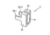
図2aは、図1の注射デバイス1に解放可能に取り付け予定の補足的デバイス2の一実施形態の概略図である。補足的デバイス2は、図1の注射デバイス1のハウジング10を取り囲むように構成された嵌合ユニットを有するハウジング20を含み、したがって、補足的デバイス2は、注射デバイス1のハウジング10上にしっかりと位置するが、それにもかかわらず、たとえば注射デバイス1が空になり、交換しなければならないときは、注射デバイス1から取り外し可能である。図2aは、非常に概略的な図であり、物理的配置の詳細については、図2bを参照しながら以下で説明する。
FIG. 2a is a schematic view of one embodiment of a
補足的デバイス2は、注射デバイス1から情報を集める光センサおよび音響的センサを収容する。情報は、補足的デバイス2の表示ユニット21を介して表示される。注射デバイス1の投薬量窓13は、注射デバイス1に取り付けられたときの補足的デバイス2によって遮られる。
The
補足的デバイス2は、ボタン22として概略的に示す3つの使用者入力変換器(user input transducer)をさらに含む。これらの入力変換器22により、使用者は、補足的デバイス2のオン/オフを切り替え、活動をトリガし(たとえば、別のデバイスへの接続もしくは別のデバイスとのペアリング(pairing)を確立し、かつ/もしくは補足的デバイス2から別のデバイスへの情報の伝送をトリガする)、または何かを確認することが可能になる。
The
図2bは、図1の注射デバイス1に解放可能に取り付け予定の補足的デバイス2の第2の実施形態の概略図である。補足的デバイス2は、図1の注射デバイス1のハウジング10を取り囲むように構成された嵌合ユニットを有するハウジング20を含み、したがって、補足的デバイス2は、注射デバイス1のハウジング10上にしっかりと位置するが、それにもかかわらず注射デバイス1から取り外し可能である。
FIG. 2b is a schematic view of a second embodiment of a
情報は、補足的デバイス2の表示ユニット21を介して表示される。注射デバイス1の投薬量窓13は、注射デバイス1に取り付けられたときの補足的デバイス2によって遮られる。
Information is displayed via the
補足的デバイス2は、3つの使用者入力ボタンまたはスイッチをさらに含む。第1のボタン22は、電源オン/オフボタンであり、このボタンを介して、たとえば補足的デバイス2のオンおよびオフを切り替えることができる。第2のボタン33は、通信ボタンである。第3のボタン34は、確認またはOKボタンである。ボタン22、33、34は、任意の適した形の機械式スイッチとすることができる。これらの入力ボタン22により、使用者は、補足的デバイス2のオン/オフを切り替え、活動をトリガし(たとえば、別のデバイスへの接続もしくは別のデバイスとのペアリングを確立し、かつ/もしくは補足的デバイス2から別のデバイスへの情報の伝送をトリガする)、または何かを確認することが可能になる。
The
図2cは、図1の注射デバイス1に解放可能に取り付け予定の補足的デバイス2の第3の実施形態の概略図である。補足的デバイス2は、図1の注射デバイス1のハウジング10を取り囲むように構成された嵌合ユニットを有するハウジング20を含み、したがって、補足的デバイス2は、注射デバイス1のハウジング10上にしっかりと位置するが、それにもかかわらず注射デバイス1から取り外し可能である。
Fig. 2c is a schematic view of a third embodiment of a
情報は、補足的デバイス2の表示ユニット21を介して表示される。注射デバイス1の投薬量窓13は、注射デバイス1に取り付けられたときの補足的デバイス2によって遮られる。
Information is displayed via the
補足的デバイス2は、タッチセンシティブ入力変換器35をさらに含む。補足的デバイス2はまた、単一の使用者入力ボタンまたはスイッチ22を含む。ボタン22は、電源オン/オフボタンであり、このボタンを介して、たとえば補足的デバイス2のオンおよびオフを切り替えることができる。タッチセンシティブ入力変換器35を使用して、活動をトリガし(たとえば、別のデバイスへの接続もしくは別のデバイスとのペアリングを確立し、かつ/もしくは補足的デバイス2から別のデバイスへの情報の伝送をトリガする)、または何かを確認することができる。
The
図3aおよび図3bは、補足的デバイス(図2aおよび図2bの補足的デバイスなど)を注射デバイスとともに使用するときのデバイス間の機能の可能な分布を示す。 Figures 3a and 3b show possible distributions of functionality between devices when a supplemental device (such as the supplemental device of Figures 2a and 2b) is used with an injection device.
図3aの配列4では、補足的デバイス41(図2aおよび図2bの補足的デバイスなど)は、注射デバイス40からの情報を判定し、この情報(たとえば、注射予定の薬剤のタイプおよび/または用量)を血糖監視システム42へ(たとえば、有線または無線接続を介して)提供する。
In the array 4 of FIG. 3a, a supplemental device 41 (such as the supplemental device of FIGS. 2a and 2b) determines information from the
血糖監視システム42(たとえば、デスクトップコンピュータ、パーソナルデジタルアシスタント、移動電話、タブレットコンピュータ、ノートブック、ネットブック、またはウルトラブックとして実施することができる)は、患者がこれまでに受けた注射の記録を取る(検出された放出された用量に基づき、または放出された用量に基づいて注射された用量を判定することにより、たとえば、放出された用量の事前に画成された割合が患者によって完全に受けられるとは限らないと仮定することによる)。血糖監視システム42は、たとえば、この患者に対する次の注射のインスリンのタイプおよび/または用量を提案することができる。この提案は、患者が受けた1つまたはそれ以上の過去の注射および血糖計43によって測定される現在の血糖レベルに関する情報に基づいて行うことができ、血糖監視システム42へ(たとえば、有線または無線接続を介して)提供することができる。この際、血糖計43は、患者の小さい血液プローブを(たとえば、キャリア材料上に)受けて、この血液プローブに基づいて患者の血糖レベルを判定するように構成された別個のデバイスとして実施することができる。しかし、血糖計43はまた、少なくとも一時的に患者内へ、たとえば患者の眼中または皮膚の下へ移植されるデバイスとすることができる。
The blood glucose monitoring system 42 (which can be implemented, for example, as a desktop computer, personal digital assistant, mobile phone, tablet computer, notebook, netbook, or ultrabook) keeps track of the injections the patient has received so far (E.g., by determining the injected dose based on the detected released dose or based on the released dose, for example, a pre-defined percentage of the released dose is fully received by the patient By assuming that this is not always the case). The blood
図3bは、図3aの血糖計43が図3aの血糖監視システム42内へ含まれている修正された配列4’であり、したがって図3bの修正された血糖監視システム42’が得られる。図3aの注射デバイス40および補足的デバイス41の機能性は、この修正による影響を受けない。また、血糖監視システム42’内へ組み合わせられた血糖監視システム42および血糖計43の機能性は、基本的に変化しない。ただし、血糖監視システム42と血糖計43の両方がここでは同じデバイス内に含まれ、したがってこれらのデバイス間の外部の有線または無線通信が必要ではなくなる。しかし、血糖監視システム42と血糖計43との間の通信は、システム42’内で行われる。
FIG. 3b is a modified array 4 'in which the
図4は、図1の注射デバイス1に取り付けられた状態の図2aの補足的デバイス2の概略図を示す。
FIG. 4 shows a schematic view of the
補足的デバイス2のハウジング20により、複数の構成要素が含まれる。これらの構成要素は、プロセッサ24によって制御され、プロセッサ24は、たとえば、マイクロプロセッサ、デジタル信号プロセッサ(DSP)、特定用途向け集積回路(ASIC)、フィールドプログラマブルゲートアレイ(FPGA)などとすることができる。プロセッサ24は、プログラムメモリ240内に記憶されたプログラムコード(たとえば、ソフトウェアまたはファームウェア)を実行し、主メモリ241を使用して、たとえば中間結果を記憶する。また、主メモリ241を使用して、実行された放出/注射に関するログブックを記憶することもできる。プログラムメモリ240は、たとえば、読取り専用メモリ(ROM)とすることができ、主メモリは、たとえば、ランダムアクセスメモリ(RAM)とすることができる。
The
図2bに示すものなどの実施形態では、プロセッサ24は、第1のボタン22と相互作用し、第1のボタン22を介して、たとえば補足的デバイス2のオンおよびオフを切り替えることができる。第2のボタン33は、通信ボタンである。第2のボタンを使用して、別のデバイスへの接続の確立をトリガし、または別のデバイスへの情報の伝送をトリガすることができる。第3のボタン34は、確認またはOKボタンである。第3のボタン34を使用して、補足的デバイス2の使用者に提示された情報を承認することができる。
In an embodiment such as that shown in FIG. 2 b, the
図2cに示すものなどの実施形態では、ボタン33、34の2つを省略することができる。代わりに、1つまたはそれ以上の容量センサまたは他のタッチセンサが設けられる。
In embodiments such as that shown in FIG. 2c, two of the
プロセッサ24は、液晶ディスプレイ(LCD)として現在実施される表示ユニット21を制御する。表示ユニット21は、たとえば注射デバイス1の現在の設定または投与予定の次の注射に関する情報を、補足的デバイス2の使用者に表示するために使用される。表示ユニット21はまた、たとえば使用者入力を受けるためのタッチスクリーンディスプレイとして実施することができる。
The
プロセッサ24はまた、投薬量窓13の画像を取り込むことが可能な光学式文字認識(OCR)リーダとして実施される光センサ25を制御し、投薬量窓13内には、現在の選択用量が表示される(注射デバイス1内に収容されたスリーブ19上に印刷された数字を用い、これらの数字は、投薬量窓13を通して見える)。OCRリーダ25はさらに、取り込まれた画像から文字(たとえば、数字)を認識し、この情報をプロセッサ24に提供することが可能である。別法として、補足的デバイス2内のユニット25は、画像を取り込み、取り込まれた画像に関する情報をプロセッサ24に提供するための光センサ、たとえばカメラのみとすることができる。次いで、プロセッサ24は、取り込まれた画像上でOCRを実行することを担う。
The
プロセッサ24はまた、投薬量窓13を照明するように発光ダイオード(LED)29などの光源を制御し、投薬量窓13内に、現在の選択用量が表示される。光源の前では、拡散器、たとえば1片のアクリルガラスから作られた拡散器を使用することができる。さらに、光センサは、拡大(たとえば、3:1より大きい拡大)をもたらすレンズ(たとえば、非球面レンズ)を含むことができる。
The
プロセッサ24は、注射デバイス1のハウジング10の光学特性、たとえば色または陰影を判定するように構成された光度計26をさらに制御する。光学特性は、ハウジング10の特有の部分のみに存在することができ、たとえば注射デバイス1内に含まれるスリーブ19またはインスリン容器の色または色コーディングとすることができ、この色または色コーディングは、たとえば、ハウジング10内(および/またはスリーブ19内)のさらなる窓を通して見えるようにすることができる。次いで、この色に関する情報は、プロセッサ24に提供され、次いで、プロセッサ24は、注射デバイス1のタイプまたは注射デバイス1内に収容されているインスリンのタイプを判定することができる(たとえば、Solostar Lantusは紫色を有し、Solostar Apidraは青色を有する)。別法として、光度計26の代わりにカメラユニットを使用することができ、次いで、ハウジング、スリーブ、またはインスリン容器の画像を、プロセッサ24に提供し、画像処理によってハウジング、スリーブ、またはインスリン容器の色を判定することができる。さらに、1つまたはそれ以上の光源を設けて、光度計26の読取りを改善することができる。光源は、光度計26による色の検出を改善するために、特定の波長またはスペクトルの光を提供することができる。光源は、たとえば投薬量窓13による望ましくない反射が回避または低減されるように配置することができる。例示的な一実施形態では、光度計26の代わりに、または光度計26に加えて、カメラユニットを導入して、注射デバイスおよび/またはその中に収容されている薬剤に関係するコード(たとえばバーコード、たとえば1次元または2次元のバーコードとすることができる)を検出することができる。このコードは、たとえば、いくつかの例を挙げると、注射デバイス1内に収容されたハウジング10または薬剤容器上に配置することができる。このコードは、たとえば、注射デバイスおよび/もしくは薬剤のタイプ、ならびに/またはさらなる特性(たとえば、有効期日)を示すことができる。
The
プロセッサ24は、注射デバイス1によって生じる音を感知するように構成された音響センサ27をさらに制御する(かつ/または音響センサ27から信号を受ける)。そのような音は、たとえば、投薬量ノブ12を回すことによって用量がダイヤル設定されたとき、および/または注射ボタン11を押下することによって用量が放出/注射されたとき、および/またはプライムショットが実行されたときに、発生させることができる。これらの活動は、機械的に類似しているが、それにもかかわらず、異なる音を発する(これはまた、これらの活動を示す電子音にも当てはまることができる)。音響センサ27および/またはプロセッサ24は、これらの異なる音を区別して、たとえば(プライムショットだけではなく)注射が行われたことを安全に認識することを可能にするように構成することができる。
The
プロセッサ24は、たとえば注射デバイス1の動作状態に関係することができる音響的信号を、たとえば使用者へのフィードバックとして生じさせるように構成された音響的信号生成器23をさらに制御する。たとえば、音響的信号は、注射予定の次の用量に対する注意として、またはたとえば誤使用の場合に警報信号として、音響的信号生成器23によって発することができる。音響的信号生成器は、たとえば、ブザーまたは拡声器として実施することができる。また、音響的信号生成器23に加えて、または音響的信号生成器23の代替として、触覚信号生成器(図示せず)を使用して、たとえば振動によって、触覚フィードバックを提供することもできる。
The
プロセッサ24は、別のデバイスとの間で情報を無線で伝送および/または受信するように構成された無線ユニット28を制御する。そのような伝送は、たとえば、無線伝送または光伝送に基づいて行うことができる。いくつかの実施形態では、無線ユニット28は、Bluetoothトランシーバである。別法として、無線ユニット28は、別のデバイスとの間で情報を有線で、たとえばケーブルまたはファイバ接続を介して伝送および/または受信するように構成された有線ユニットによって代用または補完することができる。データが伝送されるとき、転送されるデータ(値)の単位は、明示的または暗黙的に定義することができる。たとえば、インスリン用量の場合、常に国際単位(IU)を使用することができ、またはそうでない場合、使用される単位は、たとえばコード化された形式で、明示的に転送することができる。
The
プロセッサ24は、ペン1が存在するかどうかを検出するように、すなわち補足的デバイス2が注射デバイス1にカップリングされているかどうかを検出するように動作可能なペン検出スイッチ30から、入力を受ける。
The
電池32が、電源31を介してプロセッサ24および他の構成要素に電力を供給する。
A
したがって、図4の補足的デバイス2は、注射デバイス1の状況および/または使用に関係する情報を判定することが可能である。この情報は、デバイスの使用者が使用できるように、ディスプレイ21上に表示される。情報は、補足的デバイス2自体によって処理することができ、または別のデバイス(たとえば、血糖監視システム)へ少なくとも部分的に提供することができる。
Accordingly, the
プロセッサ24は、プロセッサ装置を構成する。OCRリーダ25は、ダイヤル設定された薬剤の用量を検出するように動作可能な用量ダイヤル設定式検出器を構成する。OCRリーダ25はまた、薬剤の用量が送達されたことを判定する用量送達判定器を構成することができる。送達された薬剤の数量(用量)を判定する数量判定器については、図9〜11を参照しながら後述する。プロセッサ24は、現在の時間を判定するように構成されたクロックの機能を提供する。
The
図5a〜5cは、本発明による方法の実施形態の流れ図である。これらの方法は、たとえば、補足的デバイス2のプロセッサ24(図2bおよび図4参照)によって実行することができるだけではなく、図2bの補足的デバイス2のプロセッサによって実行することもでき、たとえば、補足的デバイス2のプログラムメモリ240内に記憶することができ、プログラムメモリ240は、たとえば、図6の有形の記憶媒体60の形状をとることができる。
Figures 5a-5c are flow diagrams of embodiments of the method according to the invention. These methods can be performed not only by the
図5aは、図3aおよび図3bに示すシナリオで実行される方法工程を示し、注射デバイス40から補足的デバイス41によって読み取られた情報は、血糖監視システム42または42’に提供されるが、血糖監視システム42または42’から戻る情報は受けない。
FIG. 5a shows the method steps performed in the scenario shown in FIGS. 3a and 3b, where the information read by the
流れ図500は、たとえば、補足的デバイスがオンに切り替えられたとき、またはその他の方法で起動されたときに開始する。工程501で、たとえば、すでに上述したように、色認識に基づいて、または注射デバイスもしくはその構成要素上に印刷されたコードの認識に基づいて、注射デバイスによって提供される薬剤、たとえばインスリンのタイプが判定される。患者が常に同じタイプの薬剤を摂取し、この単一のタイプの薬剤を有する注射デバイスのみを使用する場合、薬剤のタイプの検出は必要でないことがある。さらに、薬剤のタイプの判定は、その他の方法で確実にすることもできる(たとえば、図4に示す鍵−凹部の対によって、補足的デバイスが1つの特有の注射デバイスのみと使用可能になり、次いでこの注射デバイスがこの単一のタイプの薬剤のみを提供することができることを確実にする)。
Flow diagram 500 begins, for example, when a supplemental device is switched on or otherwise activated. In
工程502で、たとえば上記のように注射デバイスの投薬量窓上に示されている情報のOCRによって、現在の選択用量が判定される。次いで、工程503で、この情報は注射デバイスの使用者に表示される。
At
工程504で、たとえば上記のように音認識によって、放出が行われたかどうかが確かめられる。工程504では、プライムショットと(生物内への)実際の注射とを区別することができ、それは、注射デバイスによって生じるそれぞれ異なる音に基づいて、かつ/または放出される用量に基づいて(たとえば、小さい用量、たとえば事前に画成された単位の量、たとえば4または3単位より小さい用量は、プライムショットに属すと見なすことができ、より大きい用量は、実際の注射に属すと見なされる)行われる。
In
送達された薬剤の数量は、図9〜11を参照しながら後述する方法で判定される。 The quantity of the delivered drug is determined by a method described later with reference to FIGS.
放出が行われた場合、送達された用量、および該当する場合は薬剤(たとえば、インスリン)のタイプが、主メモリ241内に記憶され、後にこのデータは、主メモリ241から、別のデバイス、たとえば血糖監視システムへ伝送することができる。放出の性質、たとえば放出がプライムショットとして実行されたか、それとも実際の注射として実行されたかに関する区別が行われた場合、この情報もまた、主メモリ241内に記憶することができ、場合によっては後に伝送することができる。注射が実行された場合、工程505で、ディスプレイ21上に用量が表示される。また、最終の注射からの時間が表示される。この時間は、注射直後には0または1分である。最終の用量からの時間は、断続的に表示することができる。たとえば、この時間は、注射された薬剤の名称または他の識別情報、たとえばApidraまたはLantusと交互に表示することができる。
If a release is made, the delivered dose and, if applicable, the type of drug (eg, insulin) is stored in
工程504で放出が実行されなかった場合、工程502および503が繰り返される。
If no release was performed at
送達された用量および時間データの表示後、流れ図500は終了する。
After displaying the delivered dose and time data, the
図5bは、光センサのみを使用することに基づいて選択用量が判定されるときに実行される例示的な方法工程をより詳細に示す。たとえば、これらの工程は、図5aの工程502で実行することができる。
FIG. 5b shows in more detail exemplary method steps that are performed when a selected dose is determined based on using only a light sensor. For example, these steps can be performed at
工程901で、補足的デバイス2の光センサ25などの光センサによって、サブ画像が取り込まれる。取り込まれたサブ画像は、たとえば、注射デバイス1の投薬量窓13の少なくとも一部の画像であり、現在の選択用量が表示される(たとえば、注射デバイス1のスリーブ19上に印刷され、投薬量窓13を通して見える数字および/または目盛りを用いる)。たとえば、取り込まれたサブ画像は、低い分解能を有することができ、かつ/またはスリーブ19のうち、投薬量窓13を通して見える部分の一部のみを示す。たとえば、取り込まれたサブ画像は、注射デバイス1のスリーブ19のうち、投薬量窓13を通して見える部分上に印刷された数字または目盛りを示す。画像を取り込んだ後、この画像は、たとえば次のようにさらに処理される:
事前に取り込まれた背景画像による分割;
さらなる評価のために画素数を低減させるための画像(複数可)のビニング;
照明の強度の変動を低減させるための画像(複数可)の正規化;
画像(複数可)のシャーリング(sheering);および/または
固定の閾値と比較することによる画像(複数可)の2値化。
In
Segmentation by pre-captured background image;
Binning of image (s) to reduce the number of pixels for further evaluation;
Normalization of image (s) to reduce variations in illumination intensity;
Shearing of image (s); and / or binarization of image (s) by comparing to a fixed threshold.
これらの工程のいくつかまたはすべては、該当する場合、たとえば十分に大きい光センサ(たとえば、十分に大きい画素を有するセンサ)が使用される場合、省略することができる。 Some or all of these steps can be omitted if applicable, for example if a sufficiently large light sensor (eg, a sensor having sufficiently large pixels) is used.
工程902で、取り込まれたサブ画像に変化があるか否かが判定される。たとえば、現在取り込まれているサブ画像と、事前に取り込まれたサブ画像(複数可)とを比較して、変化があるか否かを判定することができる。工程902では、事前に取り込まれたサブ画像との比較は、事前に取り込まれたサブ画像のうち、現在のサブ画像が取り込まれる直前に取り込まれたサブ画像、および/または事前に取り込まれたサブ画像のうち、現在のサブ画像が取り込まれる前の指定の期間(たとえば、0.1秒)内に取り込まれたサブ画像に制限することができる。この比較は、現在取り込まれているサブ画像および事前に取り込まれたサブ画像上で実行されるパターン認識などの画像分析技法に基づいて行うことができる。たとえば、現在取り込まれているサブ画像および事前に取り込まれたサブ画像内に示されている、投薬量窓13を通して見える目盛りおよび/または数字のパターンが、変化したかどうかを分析することができる。たとえば、画像内で特定の寸法および/または縦横比を有するパターンを探すことができ、これらのパターンと事前に保存されているパターンとを比較することができる。工程901および902は、取り込まれた画像内の変化の検出に対応することができる。
In
工程902で、サブ画像に変化があると判定された場合、工程901が繰り返される。そうでない場合は、工程903で、補足的デバイス2の光センサ25などの光センサによって画像が取り込まれる。取り込まれた画像は、たとえば、注射デバイス1の投薬量窓13の画像であり、現在の選択用量が表示される(たとえば、注射デバイス1のスリーブ19上に印刷され、投薬量窓13を通して見える数字および/または目盛りを用いる)。たとえば、取り込まれた画像は、取り込まれたサブ画像の分解能より高い分解能を有することができる。取り込まれた画像は、少なくとも、注射デバイス1のスリーブ19上に印刷され、投薬量窓13を通して見える数字を示す。
If it is determined in
工程904で、工程903で取り込まれた画像上で光学式文字認識(OCR)を実行し、注射デバイス1のスリーブ19上に印刷され、投薬量窓13を通して見える数字を認識する。なぜなら、これらの数字は、(現在の)選択用量に対応するからである。認識された数字に応じて、たとえば選択用量を表す値を認識された数字に設定することによって、選択用量が判定される。
At step 904, optical character recognition (OCR) is performed on the image captured at
工程905で、判定された選択用量に変化があるか否か、および場合により、判定された選択用量がゼロに等しくないか否かが判定される。たとえば、現在判定されている選択用量と、事前に判定された選択用量(複数可)とを比較して、変化があるか否かを判定することができる。工程905では、事前に判定された選択用量(複数可)との比較は、事前に判定された選択用量(複数可)のうち、現在の選択用量が判定される前の指定の期間(たとえば、3秒)内に判定されたものに制限することができる。判定された選択用量に変化がない場合、および場合により、判定された選択用量がゼロに等しくない場合、現在判定されている選択用量は、さらなる処理のために(たとえば、プロセッサ24へ)戻される/転送される。
At
したがって、投薬量ノブ12を最後に回したのが3秒より前である場合、選択用量が判定される。3秒以内またはそれより後に投薬量ノブ12が回され、かつ新しい位置が3秒より長い間変化していないままである場合、この値は、判定された選択用量と見なされる。
Thus, if the
図5cは、音響的センサおよび光センサの使用に基づいて選択用量が判定されるときに実行される方法工程をより詳細に示す。たとえば、これらの工程は、図5aの工程502で実行することができる。
FIG. 5c shows in more detail the method steps that are performed when the selected dose is determined based on the use of acoustic and light sensors. For example, these steps can be performed at
工程1001で、補足的デバイス2の音響的センサ27などの音響的センサによって音が取り込まれる。
At
工程1002で、取り込まれた音がクリック音であるか否かが判定される。取り込まれた音は、たとえば、注射デバイス1の投薬量ノブ12を回すことによって用量がダイヤル設定されたとき、および/または注射ボタン11を押下することによって用量が放出/注射されたとき、および/またはプライムショットが実行されたときに発生するクリック音とすることができる。取り込まれた音がクリック音ではない場合、工程1001が繰り返される。そうでない場合、工程1003で、補足的デバイス2の光センサ25などの光センサによって画像が取り込まれる。工程1003は、流れ図900の工程903に対応する。
In
工程1004で、工程1003で取り込まれた画像上でOCRが実行される。工程1004は、流れ図900の工程904に対応する。
At
工程1005で、判定された選択用量に変化があるか否か、および場合により、判定された選択用量がゼロに等しくないか否かが判定される。工程1005は、流れ図900の工程905に対応する。
At
補足的デバイスの消費電力に関しては、図5cに示す音響手法がわずかに有利になる可能性がある。なぜなら、図5bに示すように画像またはサブ画像を恒久的に取り込むことは、典型的には、マイクロフォンなどの音響的センサを聞くよりより多くの電力を消費するからである。 Regarding the power consumption of the supplementary device, the acoustic approach shown in FIG. 5c may be slightly advantageous. This is because permanently capturing an image or sub-image as shown in FIG. 5b typically consumes more power than listening to an acoustic sensor such as a microphone.
図6は、プログラムコード62を有するコンピュータプログラム61を含む有形の記憶媒体60(コンピュータプログラム製品)の概略図である。このプログラムコードは、たとえば、補足的デバイス内に収容されたプロセッサ、たとえば図2aおよび図4の補足的デバイス2のプロセッサ24によって実行することができる。たとえば、記憶媒体60は、図4の補足的デバイス2のプログラムメモリ240を表すことができる。記憶媒体60は、固定のメモリ、またはたとえばメモリスティックもしくはカードなどの取り外し可能なメモリとすることができる。
FIG. 6 is a schematic diagram of a tangible storage medium 60 (computer program product) that includes a
最後に、図7は、本発明の一実施形態による様々なデバイス(たとえば、図3aまたは図3bに示すシナリオにおける図4の注射デバイス1および補足的デバイス2)間の情報の流れを示す情報シーケンス図7である。注射デバイス1の状況および/または使用は、その投薬量窓の外観、注射デバイス1によって生成される音、およびハウジングの色に影響を与える。この情報は、補足的デバイス2のセンサ25、26、27、30によって、それぞれOCR信号、音響センサ信号、および光度計信号に変換され、これらの信号は、補足的デバイス2のプロセッサ24によって、それぞれダイヤル設定された用量、注射/ダイヤル設定動作、およびインスリンのタイプに関する情報に変換される。次いで、この情報は、補足的デバイス2によって血糖監視システム42に提供される。この情報の一部またはすべてが、ディスプレイ21を介して使用者に表示される。
Finally, FIG. 7 is an information sequence illustrating the flow of information between various devices (eg,
詳細に上述したように、本発明の実施形態では、標準的な注射デバイス、特にインスリンデバイスを血糖監視システムと有用かつ生産的に接続することが可能である。 As described in detail above, embodiments of the present invention allow a standard injection device, particularly an insulin device, to be usefully and productively connected with a blood glucose monitoring system.
本発明の実施形態では、血糖監視システムが無線または他の通信能力を有するものとして、補足的デバイスを導入し、この接続を可能にする。 In an embodiment of the present invention, the supplemental device is introduced to enable this connection as the blood glucose monitoring system has wireless or other communication capabilities.
血糖監視システムとインスリン注射デバイスとの間の接続から得られる利益には、とりわけ、注射デバイスの使用者による間違いの低減、および取扱い工程の低減があり、血糖監視システム、特に注射された最終の用量および最新の血糖値に基づいて次の用量に対する案内を提供する機能性を有する血糖監視システムへ、注射されたインスリン単位を手動で転送する必要がなくなる。 Benefits derived from the connection between the blood glucose monitoring system and the insulin injection device include, among other things, reduced errors by the user of the injection device and reduced handling steps, and the blood glucose monitoring system, particularly the final dose injected And there is no need to manually transfer the injected insulin units to a blood glucose monitoring system that has the functionality to provide guidance for the next dose based on the latest blood glucose level.
例示的な実施形態を参照して上述したように、使用者/患者が新しいインスリンペンを入手したとき、使用者は、このペンに補足的デバイスを取り付ける。補足的デバイスは、注射された用量を読み出す。補足的デバイスはまた、インスリン滴定能力を有する血糖監視システムへ、その用量を転送することができる。複数のインスリンをとる患者の場合、補足的デバイスは、そのインスリンタイプに対するデバイス構造を認識し、また、この情報を血糖監視システムへ伝送することができる。 As described above with reference to the exemplary embodiment, when the user / patient obtains a new insulin pen, the user attaches a supplemental device to the pen. The supplementary device reads the injected dose. The supplemental device can also transfer the dose to a blood glucose monitoring system with insulin titration capability. For patients taking multiple insulins, the supplemental device can recognize the device structure for that insulin type and transmit this information to the blood glucose monitoring system.
例示的な実施形態では、ディスプレイ、たとえば図2aおよび図4のLCDディスプレイ21上に示される情報はまた、音信号に変換することができ、この音信号は、スピーカを通じて、たとえばプロセッサ24によって音響的信号生成器23を使用して実施されるテキストを音声に変換する機能性によって、使用者に対して再生される。したがって、視覚障害のある使用者にとって、ダイヤル設定された用量、推奨される用量、推奨される投与時間など、補足的デバイス2の情報へのアクセスを改善することができる。
In the exemplary embodiment, the information shown on the display, eg,
本発明の実施形態を使用するとき、使用者は、とりわけ、以下の利点を有する: When using embodiments of the present invention, the user has the following advantages, among others:
使用者は、最も好都合な使い捨てのインスリン注射器を使用することができる。 The user can use the most convenient disposable insulin syringe.
補足的デバイスは、取り付け可能かつ取り外し可能(再利用可能)である。 The supplemental device is attachable and removable (reusable).
注射された用量に関する情報は、血糖監視システムへ自動的に転送することができる(転送の間違いが生じなくなる)。これによって、血糖監視システムが摂取予定の用量を計算するとき、用量の案内を改善することができる。 Information about the injected dose can be automatically transferred to the blood glucose monitoring system (no transfer errors occur). This can improve dose guidance when the blood glucose monitoring system calculates the dose to be taken.
これ以上、手動データログブックを記録する必要をなくすことができる。 No more need to record manual data logbooks.
さらに、本発明によって提案する補足的デバイスを導入したときは、たとえば、薬剤(たとえば、インスリンまたはヘパリン)の第1の用量が注射されてから適当な時間が経過した後、アラーム信号を受けることによって、患者の次の用量を注射することを患者に気付かせることもできる。 Furthermore, when the supplementary device proposed by the present invention is introduced, for example, by receiving an alarm signal after an appropriate time has elapsed since the first dose of drug (eg, insulin or heparin) has been injected. The patient can also be reminded to inject the next dose of the patient.
注射された用量に関する情報は、たとえば、任意の用量計算もしくは任意の他の該当する治療案内計算のための、またはたとえば次の用量を摂取することを使用者に気付かせるためにアラーム信号を作成するための入力として、任意のコンピュータ化されたシステムへ転送することができる。 Information about the injected dose creates an alarm signal, for example, for any dose calculation or any other applicable treatment guidance calculation, or to remind the user to take the next dose, for example Can be transferred to any computerized system as input.
本明細書で使用する用語「薬物」または「薬剤」は、少なくとも1つの薬学的に活性な化合物を含む医薬製剤を意味し、
ここで、一実施形態において、薬学的に活性な化合物は、最大1500Daまでの分子量を有し、および/または、ペプチド、タンパク質、多糖類、ワクチン、DNA、RNA、酵素、抗体もしくはそのフラグメント、ホルモンもしくはオリゴヌクレオチド、または上述の薬学的に活性な化合物の混合物であり、
ここで、さらなる実施形態において、薬学的に活性な化合物は、糖尿病、または糖尿病性網膜症などの糖尿病関連の合併症、深部静脈血栓塞栓症または肺血栓塞栓症などの血栓塞栓症、急性冠症候群(ACS)、狭心症、心筋梗塞、がん、黄斑変性症、炎症、枯草熱、アテローム性動脈硬化症および/または関節リウマチの処置および/または予防に有用であり、
ここで、さらなる実施形態において、薬学的に活性な化合物は、糖尿病または糖尿病性網膜症などの糖尿病に関連する合併症の処置および/または予防のための少なくとも1つのペプチドを含み、
ここで、さらなる実施形態において、薬学的に活性な化合物は、少なくとも1つのヒトインスリンもしくはヒトインスリン類似体もしくは誘導体、グルカゴン様ペプチド(GLP−1)もしくはその類似体もしくは誘導体、またはエキセンジン−3もしくはエキセンジン−4もしくはエキセンジン−3もしくはエキセンジン−4の類似体もしくは誘導体を含む。
The term “drug” or “drug” as used herein means a pharmaceutical formulation comprising at least one pharmaceutically active compound,
Here, in one embodiment, the pharmaceutically active compound has a molecular weight of up to 1500 Da and / or a peptide, protein, polysaccharide, vaccine, DNA, RNA, enzyme, antibody or fragment thereof, hormone Or an oligonucleotide, or a mixture of the above-mentioned pharmaceutically active compounds,
Here, in a further embodiment, the pharmaceutically active compound is diabetic or diabetic-related complications such as diabetic retinopathy, thromboembolism such as deep vein thromboembolism or pulmonary thromboembolism, acute coronary syndrome (ACS), useful for the treatment and / or prevention of angina pectoris, myocardial infarction, cancer, macular degeneration, inflammation, hay fever, atherosclerosis and / or rheumatoid arthritis,
Here, in a further embodiment, the pharmaceutically active compound comprises at least one peptide for the treatment and / or prevention of diabetes-related complications such as diabetes or diabetic retinopathy,
Here, in a further embodiment, the pharmaceutically active compound is at least one human insulin or human insulin analogue or derivative, glucagon-like peptide (GLP-1) or analogue or derivative thereof, or exendin-3 or exendin -4 or exendin-3 or analogs or derivatives of exendin-4.
インスリン類似体は、たとえば、Gly(A21),Arg(B31),Arg(B32)ヒトインスリン;Lys(B3),Glu(B29)ヒトインスリン;Lys(B28),Pro(B29)ヒトインスリン;Asp(B28)ヒトインスリン;B28位におけるプロリンがAsp、Lys、Leu、Val、またはAlaで置き換えられており、B29位において、LysがProで置き換えられていてもよいヒトインスリン;Ala(B26)ヒトインスリン;Des(B28−B30)ヒトインスリン;Des(B27)ヒトインスリン、およびDes(B30)ヒトインスリンである。 Insulin analogues include, for example, Gly (A21), Arg (B31), Arg (B32) human insulin; Lys (B3), Glu (B29) human insulin; Lys (B28), Pro (B29) human insulin; Asp ( B28) human insulin; proline at position B28 is replaced with Asp, Lys, Leu, Val, or Ala; at position B29, human insulin where Lys may be replaced with Pro; Ala (B26) human insulin; Des (B28-B30) human insulin; Des (B27) human insulin, and Des (B30) human insulin.
インスリン誘導体は、たとえば、B29−N−ミリストイル−des(B30)ヒトインスリン;B29−N−パルミトイル−des(B30)ヒトインスリン;B29−N−ミリストイルヒトインスリン;B29−N−パルミトイルヒトインスリン;B28−N−ミリストイルLysB28ProB29ヒトインスリン;B28−N−パルミトイル−LysB28ProB29ヒトインスリン;B30−N−ミリストイル−ThrB29LysB30ヒトインスリン;B30−N−パルミトイル−ThrB29LysB30ヒトインスリン;B29−N−(N−パルミトイル−γ−グルタミル)−des(B30)ヒトインスリン;B29−N−(N−リトコリル−γ−グルタミル)−des(B30)ヒトインスリン;B29−N−(ω−カルボキシヘプタデカノイル)−des(B30)ヒトインスリン、およびB29−N−(ω−カルボキシヘプタデカノイル)ヒトインスリンである。 Insulin derivatives include, for example, B29-N-myristoyl-des (B30) human insulin; B29-N-palmitoyl-des (B30) human insulin; B29-N-myristoyl human insulin; B29-N-palmitoyl human insulin; B28- N-myristoyl LysB28ProB29 human insulin; B28-N-palmitoyl-LysB28ProB29 human insulin; B30-N-myristoyl-ThrB29LysB30 human insulin; B30-N-palmitoyl-ThrB29LysB30 human insulin; B29-N- (N-palmitoyl) -Des (B30) human insulin; B29-N- (N-ritocryl-γ-glutamyl) -des (B30) human insulin; B29-N- (ω- Carboxymethyl hepta decanoyl) -des (B30) human insulin, and B29-N- (ω- carboxyheptadecanoyl) human insulin.
エキセンジン−4は、たとえば、H−His−Gly−Glu−Gly−Thr−Phe−Thr−Ser−Asp−Leu−Ser−Lys−Gln−Met−Glu−Glu−Glu−Ala−Val−Arg−Leu−Phe−Ile−Glu−Trp−Leu−Lys−Asn−Gly−Gly−Pro−Ser−Ser−Gly−Ala−Pro−Pro−Pro−Ser−NH2配列のペプチドであるエキセンジン−4(1−39)を意味する。 Exendin-4 is, for example, H-His-Gly-Glu-Gly-Thr-Phe-Thr-Ser-Asp-Leu-Ser-Lys-Gln-Met-Glu-Glu-Glu-Ala-Val-Arg-Leu Exendin-4 (1-39, which is a peptide of the sequence -Phe-Ile-Glu-Trp-Leu-Lys-Asn-Gly-Gly-Pro-Ser-Ser-Gly-Ala-Pro-Pro-Pro-Ser-NH2 ).
エキセンジン−4誘導体は、たとえば、以下のリストの化合物:
H−(Lys)4−desPro36,desPro37エキセンジン−4(1−39)−NH2、
H−(Lys)5−desPro36,desPro37エキセンジン−4(1−39)−NH2、
desPro36エキセンジン−4(1−39)、
desPro36[Asp28]エキセンジン−4(1−39)、
desPro36[IsoAsp28]エキセンジン−4(1−39)、
desPro36[Met(O)14,Asp28]エキセンジン−4(1−39)、
desPro36[Met(O)14,IsoAsp28]エキセンジン−(1−39)、
desPro36[Trp(O2)25,Asp28]エキセンジン−4(1−39)、
desPro36[Trp(O2)25,IsoAsp28]エキセンジン−4(1−39)、
desPro36[Met(O)14,Trp(O2)25,Asp28]エキセンジン−4(1−39)、
desPro36[Met(O)14Trp(O2)25,IsoAsp28]エキセンジン−4(1−39);または
desPro36[Asp28]エキセンジン−4(1−39)、
desPro36[IsoAsp28]エキセンジン−4(1−39)、
desPro36[Met(O)14,Asp28]エキセンジン−4(1−39)、
desPro36[Met(O)14,IsoAsp28]エキセンジン−(1−39)、
desPro36[Trp(O2)25,Asp28]エキセンジン−4(1−39)、
desPro36[Trp(O2)25,IsoAsp28]エキセンジン−4(1−39)、
desPro36[Met(O)14,Trp(O2)25,Asp28]エキセンジン−4(1−39)、
desPro36[Met(O)14,Trp(O2)25,IsoAsp28]エキセンジン−4(1−39)、
(ここで、基−Lys6−NH2が、エキセンジン−4誘導体のC−末端に結合していてもよい);
Exendin-4 derivatives are, for example, compounds of the following list:
H- (Lys) 4-desPro36, desPro37 exendin-4 (1-39) -NH2,
H- (Lys) 5-desPro36, desPro37 exendin-4 (1-39) -NH2,
desPro36 exendin-4 (1-39),
desPro36 [Asp28] exendin-4 (1-39),
desPro36 [IsoAsp28] exendin-4 (1-39),
desPro36 [Met (O) 14, Asp28] exendin-4 (1-39),
desPro36 [Met (O) 14, IsoAsp28] Exendin- (1-39),
desPro36 [Trp (O2) 25, Asp28] exendin-4 (1-39),
desPro36 [Trp (O2) 25, IsoAsp28] exendin-4 (1-39),
desPro36 [Met (O) 14, Trp (O2) 25, Asp28] exendin-4 (1-39),
desPro36 [Met (O) 14Trp (O2) 25, IsoAsp28] Exendin-4 (1-39); or desPro36 [Asp28] Exendin-4 (1-39),
desPro36 [IsoAsp28] exendin-4 (1-39),
desPro36 [Met (O) 14, Asp28] exendin-4 (1-39),
desPro36 [Met (O) 14, IsoAsp28] Exendin- (1-39),
desPro36 [Trp (O2) 25, Asp28] exendin-4 (1-39),
desPro36 [Trp (O2) 25, IsoAsp28] exendin-4 (1-39),
desPro36 [Met (O) 14, Trp (O2) 25, Asp28] exendin-4 (1-39),
desPro36 [Met (O) 14, Trp (O 2) 25, IsoAsp 28] Exendin-4 (1-39),
(Wherein the group -Lys6-NH2 may be attached to the C-terminus of the exendin-4 derivative);
または、以下の配列のエキセンジン−4誘導体:
desPro36エキセンジン−4(1−39)−Lys6−NH2(AVE0010)、
H−(Lys)6−desPro36[Asp28]エキセンジン−4(1−39)−Lys6−NH2、
desAsp28Pro36,Pro37,Pro38エキセンジン−4(1−39)−NH2、
H−(Lys)6−desPro36,Pro38[Asp28]エキセンジン−4(1−39)−NH2、
H−Asn−(Glu)5desPro36,Pro37,Pro38[Asp28]エキセンジン−4(1−39)−NH2、
desPro36,Pro37,Pro38[Asp28]エキセンジン−4(1−39)−(Lys)6−NH2、
H−(Lys)6−desPro36,Pro37,Pro38[Asp28]エキセンジン−4(1−39)−(Lys)6−NH2、
H−Asn−(Glu)5−desPro36,Pro37,Pro38[Asp28]エキセンジン−4(1−39)−(Lys)6−NH2、
H−(Lys)6−desPro36[Trp(O2)25,Asp28]エキセンジン−4(1−39)−Lys6−NH2、
H−desAsp28Pro36,Pro37,Pro38[Trp(O2)25]エキセンジン−4(1−39)−NH2、
H−(Lys)6−desPro36,Pro37,Pro38[Trp(O2)25,Asp28]エキセンジン−4(1−39)−NH2、
H−Asn−(Glu)5−desPro36,Pro37,Pro38[Trp(O2)25,Asp28]エキセンジン−4(1−39)−NH2、
desPro36,Pro37,Pro38[Trp(O2)25,Asp28]エキセンジン−4(1−39)−(Lys)6−NH2、
H−(Lys)6−desPro36,Pro37,Pro38[Trp(O2)25,Asp28]エキセンジン−4(1−39)−(Lys)6−NH2、
H−Asn−(Glu)5−desPro36,Pro37,Pro38[Trp(O2)25,Asp28]エキセンジン−4(1−39)−(Lys)6−NH2、
H−(Lys)6−desPro36[Met(O)14,Asp28]エキセンジン−4(1−39)−Lys6−NH2、
desMet(O)14,Asp28Pro36,Pro37,Pro38エキセンジン−4(1−39)−NH2、
H−(Lys)6−desPro36,Pro37,Pro38[Met(O)14,Asp28]エキセンジン−4(1−39)−NH2、
H−Asn−(Glu)5−desPro36,Pro37,Pro38[Met(O)14,Asp28]エキセンジン−4(1−39)−NH2;
desPro36,Pro37,Pro38[Met(O)14,Asp28]エキセンジン−4(1−39)−(Lys)6−NH2、
H−(Lys)6−desPro36,Pro37,Pro38[Met(O)14,Asp28]エキセンジン−4(1−39)−(Lys)6−NH2、
H−Asn−(Glu)5desPro36,Pro37,Pro38[Met(O)14,Asp28]エキセンジン−4(1−39)−(Lys)6−NH2、
H−Lys6−desPro36[Met(O)14,Trp(O2)25,Asp28]エキセンジン−4(1−39)−Lys6−NH2、
H−desAsp28,Pro36,Pro37,Pro38[Met(O)14,Trp(O2)25]エキセンジン−4(1−39)−NH2、
H−(Lys)6−desPro36,Pro37,Pro38[Met(O)14,Asp28]エキセンジン−4(1−39)−NH2、
H−Asn−(Glu)5−desPro36,Pro37,Pro38[Met(O)14,Trp(O2)25,Asp28]エキセンジン−4(1−39)−NH2、
desPro36,Pro37,Pro38[Met(O)14,Trp(O2)25,Asp28]エキセンジン−4(1−39)−(Lys)6−NH2、
H−(Lys)6−desPro36,Pro37,Pro38[Met(O)14,Trp(O2)25,Asp28]エキセンジン−4(S1−39)−(Lys)6−NH2、
H−Asn−(Glu)5−desPro36,Pro37,Pro38[Met(O)14,Trp(O2)25,Asp28]エキセンジン−4(1−39)−(Lys)6−NH2;
または前述のいずれか1つのエキセンジン−4誘導体の薬学的に許容される塩もしくは溶媒和化合物
から選択される。
Or an exendin-4 derivative of the following sequence:
desPro36 exendin-4 (1-39) -Lys6-NH2 (AVE0010),
H- (Lys) 6-desPro36 [Asp28] Exendin-4 (1-39) -Lys6-NH2,
desAsp28Pro36, Pro37, Pro38 exendin-4 (1-39) -NH2,
H- (Lys) 6-desPro36, Pro38 [Asp28] Exendin-4 (1-39) -NH2,
H-Asn- (Glu) 5desPro36, Pro37, Pro38 [Asp28] Exendin-4 (1-39) -NH2,
desPro36, Pro37, Pro38 [Asp28] Exendin-4 (1-39)-(Lys) 6-NH2,
H- (Lys) 6-desPro36, Pro37, Pro38 [Asp28] Exendin-4 (1-39)-(Lys) 6-NH2,
H-Asn- (Glu) 5-desPro36, Pro37, Pro38 [Asp28] Exendin-4 (1-39)-(Lys) 6-NH2,
H- (Lys) 6-desPro36 [Trp (O2) 25, Asp28] exendin-4 (1-39) -Lys6-NH2,
H-desAsp28Pro36, Pro37, Pro38 [Trp (O2) 25] exendin-4 (1-39) -NH2,
H- (Lys) 6-desPro36, Pro37, Pro38 [Trp (O2) 25, Asp28] exendin-4 (1-39) -NH2,
H-Asn- (Glu) 5-desPro36, Pro37, Pro38 [Trp (O2) 25, Asp28] exendin-4 (1-39) -NH2,
desPro36, Pro37, Pro38 [Trp (O2) 25, Asp28] exendin-4 (1-39)-(Lys) 6-NH2,
H- (Lys) 6-desPro36, Pro37, Pro38 [Trp (O2) 25, Asp28] exendin-4 (1-39)-(Lys) 6-NH2,
H-Asn- (Glu) 5-desPro36, Pro37, Pro38 [Trp (O2) 25, Asp28] exendin-4 (1-39)-(Lys) 6-NH2,
H- (Lys) 6-desPro36 [Met (O) 14, Asp28] exendin-4 (1-39) -Lys6-NH2,
desMet (O) 14, Asp28Pro36, Pro37, Pro38 exendin-4 (1-39) -NH2,
H- (Lys) 6-desPro36, Pro37, Pro38 [Met (O) 14, Asp28] exendin-4 (1-39) -NH2,
H-Asn- (Glu) 5-desPro36, Pro37, Pro38 [Met (O) 14, Asp28] exendin-4 (1-39) -NH2;
desPro36, Pro37, Pro38 [Met (O) 14, Asp28] Exendin-4 (1-39)-(Lys) 6-NH2,
H- (Lys) 6-desPro36, Pro37, Pro38 [Met (O) 14, Asp28] exendin-4 (1-39)-(Lys) 6-NH2,
H-Asn- (Glu) 5desPro36, Pro37, Pro38 [Met (O) 14, Asp28] Exendin-4 (1-39)-(Lys) 6-NH2,
H-Lys6-desPro36 [Met (O) 14, Trp (O2) 25, Asp28] Exendin-4 (1-39) -Lys6-NH2,
H-desAsp28, Pro36, Pro37, Pro38 [Met (O) 14, Trp (O2) 25] exendin-4 (1-39) -NH2,
H- (Lys) 6-desPro36, Pro37, Pro38 [Met (O) 14, Asp28] exendin-4 (1-39) -NH2,
H-Asn- (Glu) 5-desPro36, Pro37, Pro38 [Met (O) 14, Trp (O2) 25, Asp28] Exendin-4 (1-39) -NH2,
desPro36, Pro37, Pro38 [Met (O) 14, Trp (O2) 25, Asp28] Exendin-4 (1-39)-(Lys) 6-NH2,
H- (Lys) 6-desPro36, Pro37, Pro38 [Met (O) 14, Trp (O2) 25, Asp28] Exendin-4 (S1-39)-(Lys) 6-NH2,
H-Asn- (Glu) 5-desPro36, Pro37, Pro38 [Met (O) 14, Trp (O2) 25, Asp28] Exendin-4 (1-39)-(Lys) 6-NH2;
Or a pharmaceutically acceptable salt or solvate of any one of the aforementioned exendin-4 derivatives.
ホルモンは、たとえば、ゴナドトロピン(フォリトロピン、ルトロピン、コリオンゴナドトロピン、メノトロピン)、ソマトロピン(ソマトロピン)、デスモプレシン、テルリプレシン、ゴナドレリン、トリプトレリン、ロイプロレリン、ブセレリン、ナファレリン、ゴセレリンなどの、Rote Liste、2008年版、50章に列挙されている脳下垂体ホルモンまたは視床下部ホルモンまたは調節性活性ペプチドおよびそれらのアンタゴニストである。 The hormones include, for example, gonadotropin (folytropin, lutropin, corion gonadotropin, menotropin), somatropin (somatropin), desmopressin, telluripressin, gonadorelin, triptorelin, leuprorelin, buserelin, nafarelin, goserelin, etc., Rote Liste, 2008 Pituitary hormones or hypothalamic hormones or regulatory active peptides and antagonists thereof.
多糖類としては、たとえば、グルコサミノグリカン、ヒアルロン酸、ヘパリン、低分子量ヘパリン、もしくは超低分子量ヘパリン、またはそれらの誘導体、または上述の多糖類の硫酸化形態、たとえば、ポリ硫酸化形態、および/または、薬学的に許容されるそれらの塩がある。ポリ硫酸化低分子量ヘパリンの薬学的に許容される塩の例としては、エノキサパリンナトリウムがある。 Polysaccharides include, for example, glucosaminoglycan, hyaluronic acid, heparin, low molecular weight heparin, or ultra low molecular weight heparin, or derivatives thereof, or sulfated forms of the above-described polysaccharides, such as polysulfated forms, and Or a pharmaceutically acceptable salt thereof. An example of a pharmaceutically acceptable salt of polysulfated low molecular weight heparin is sodium enoxaparin.
抗体は、基本構造を共有する免疫グロブリンとしても知られている球状血漿タンパク質(約150kDa)である。これらは、アミノ酸残基に付加された糖鎖を有するので、糖タンパク質である。各抗体の基本的な機能単位は免疫グロブリン(Ig)単量体(1つのIg単位のみを含む)であり、分泌型抗体はまた、IgAなどの2つのIg単位を有する二量体、硬骨魚のIgMのような4つのIg単位を有する四量体、または哺乳動物のIgMのように5つのIg単位を有する五量体でもあり得る。 Antibodies are globular plasma proteins (about 150 kDa), also known as immunoglobulins that share a basic structure. These are glycoproteins because they have sugar chains attached to amino acid residues. The basic functional unit of each antibody is an immunoglobulin (Ig) monomer (including only one Ig unit), and the secretory antibody is also a dimer having two Ig units such as IgA, teleost It can also be a tetramer with 4 Ig units, such as IgM, or a pentamer with 5 Ig units, like mammalian IgM.
Ig単量体は、4つのポリペプチド鎖、すなわち、システイン残基間のジスルフィド結合によって結合された2つの同一の重鎖および2本の同一の軽鎖から構成される「Y」字型の分子である。それぞれの重鎖は約440アミノ酸長であり、それぞれの軽鎖は約220アミノ酸長である。重鎖および軽鎖はそれぞれ、これらの折り畳み構造を安定化させる鎖内ジスルフィド結合を含む。それぞれの鎖は、Igドメインと呼ばれる構造ドメインから構成される。これらのドメインは約70〜110個のアミノ酸を含み、そのサイズおよび機能に基づいて異なるカテゴリー(たとえば、可変すなわちV、および定常すなわちC)に分類される。これらは、2つのβシートが、保存されたシステインと他の荷電アミノ酸との間の相互作用によって一緒に保持される「サンドイッチ」形状を作り出す特徴的な免疫グロブリン折り畳み構造を有する。 An Ig monomer is a “Y” -shaped molecule composed of four polypeptide chains, two identical heavy chains and two identical light chains joined by a disulfide bond between cysteine residues. It is. Each heavy chain is about 440 amino acids long and each light chain is about 220 amino acids long. Each heavy and light chain contains intrachain disulfide bonds that stabilize these folded structures. Each chain is composed of structural domains called Ig domains. These domains contain about 70-110 amino acids and are classified into different categories (eg, variable or V, and constant or C) based on their size and function. They have a characteristic immunoglobulin fold that creates a “sandwich” shape in which two β-sheets are held together by the interaction between conserved cysteines and other charged amino acids.
α、δ、ε、γおよびμで表される5種類の哺乳類Ig重鎖が存在する。存在する重鎖の種類により抗体のアイソタイプが定義され、これらの鎖はそれぞれ、IgA、IgD、IgE、IgGおよびIgM抗体中に見出される。 There are five types of mammalian Ig heavy chains represented by α, δ, ε, γ and μ. The type of heavy chain present defines the isotype of the antibody, and these chains are found in IgA, IgD, IgE, IgG, and IgM antibodies, respectively.
異なる重鎖はサイズおよび組成が異なり、αおよびγは約450個のアミノ酸を含み、δは約500個のアミノ酸を含み、μおよびεは約550個のアミノ酸を有する。各重鎖は、2つの領域、すなわち定常領域(CH)と可変領域(VH)を有する。1つの種において、定常領域は、同じアイソタイプのすべての抗体で本質的に同一であるが、異なるアイソタイプの抗体では異なる。重鎖γ、α、およびδは、3つのタンデム型のIgドメインと、可撓性を加えるためのヒンジ領域とから構成される定常領域を有し、重鎖μおよびεは、4つの免疫グロブリン・ドメインから構成される定常領域を有する。重鎖の可変領域は、異なるB細胞によって産生された抗体では異なるが、単一B細胞またはB細胞クローンによって産生された抗体すべてについては同じである。各重鎖の可変領域は、約110アミノ酸長であり、単一のIgドメインから構成される。 Different heavy chains differ in size and composition, α and γ contain about 450 amino acids, δ contain about 500 amino acids, and μ and ε have about 550 amino acids. Each heavy chain has two regions: a constant region (C H ) and a variable region (V H ). In one species, the constant region is essentially the same for all antibodies of the same isotype, but is different for antibodies of different isotypes. Heavy chains γ, α, and δ have constant regions composed of three tandem Ig domains and a hinge region to add flexibility, and heavy chains μ and ε are four immunoglobulins -It has a constant region composed of domains. The variable region of the heavy chain is different for antibodies produced by different B cells, but is the same for all antibodies produced by a single B cell or B cell clone. The variable region of each heavy chain is approximately 110 amino acids long and is composed of a single Ig domain.
哺乳類では、λおよびκで表される2種類の免疫グロブリン軽鎖がある。軽鎖は2つの連続するドメイン、すなわち1つの定常ドメイン(CL)および1つの可変ドメイン(VL)を有する。軽鎖のおおよその長さは、211〜217個のアミノ酸である。各抗体は、常に同一である2本の軽鎖を有し、哺乳類の各抗体につき、軽鎖κまたはλの1つのタイプのみが存在する。 In mammals, there are two types of immunoglobulin light chains, denoted λ and κ. The light chain has two consecutive domains, one constant domain (CL) and one variable domain (VL). The approximate length of the light chain is 211-217 amino acids. Each antibody has two light chains that are always identical, and there is only one type of light chain κ or λ for each mammalian antibody.
すべての抗体の一般的な構造は非常に類似しているが、所与の抗体の固有の特性は、上記で詳述したように、可変(V)領域によって決定される。より具体的には、各軽鎖(VL)について3つおよび重鎖(VH)に3つの可変ループが、抗原との結合、すなわちその抗原特異性に関与する。これらのループは、相補性決定領域(CDR)と呼ばれる。VHドメインおよびVLドメインの両方からのCDRが抗原結合部位に寄与するので、最終的な抗原特異性を決定するのは重鎖と軽鎖の組合せであり、どちらか単独ではない。 Although the general structure of all antibodies is very similar, the unique properties of a given antibody are determined by the variable (V) region, as detailed above. More specifically, three variable loops for each light chain (VL) and three variable loops for heavy chain (VH) are involved in antigen binding, ie, its antigen specificity. These loops are called complementarity determining regions (CDRs). Since CDRs from both the VH and VL domains contribute to the antigen binding site, it is the combination of heavy and light chains that determines the final antigen specificity, not either alone.
「抗体フラグメント」は、上記で定義した少なくとも1つの抗原結合フラグメントを含み、そのフラグメントが由来する完全抗体と本質的に同じ機能および特異性を示す。パパインによる限定的なタンパク質消化は、Igプロトタイプを3つのフラグメントに切断する。1つの完全なL鎖および約半分のH鎖をそれぞれが含む2つの同一のアミノ末端フラグメントが、抗原結合フラグメント(Fab)である。サイズが同等であるが、鎖間ジスルフィド結合を有する両方の重鎖の半分の位置でカルボキシル末端を含む第3のフラグメントは、結晶可能なフラグメント(Fc)である。Fcは、炭水化物、相補結合部位、およびFcR結合部位を含む。限定的なペプシン消化により、Fab片とH−H鎖間ジスルフィド結合を含むヒンジ領域の両方を含む単一のF(ab’)2フラグメントが得られる。F(ab’)2は、抗原結合に対して二価である。F(ab’)2のジスルフィド結合は、Fab’を得るために切断することができる。さらに、重鎖および軽鎖の可変領域は、縮合して単鎖可変フラグメント(scFv)を形成することもできる。 “Antibody fragments” comprise at least one antigen-binding fragment as defined above and exhibit essentially the same function and specificity as the complete antibody from which the fragment is derived. Limited protein digestion with papain cleaves the Ig prototype into three fragments. Two identical amino terminal fragments, each containing one complete light chain and about half the heavy chain, are antigen-binding fragments (Fabs). A third fragment that is equivalent in size but contains a carboxyl terminus at half the positions of both heavy chains with interchain disulfide bonds is a crystallizable fragment (Fc). Fc includes a carbohydrate, a complementary binding site, and an FcR binding site. Limited pepsin digestion yields a single F (ab ') 2 fragment containing both the Fab piece and the hinge region containing the H-H interchain disulfide bond. F (ab ') 2 is divalent for antigen binding. The disulfide bond of F (ab ') 2 can be cleaved to obtain Fab'. In addition, the variable regions of the heavy and light chains can be condensed to form a single chain variable fragment (scFv).
薬学的に許容される塩は、たとえば、酸付加塩および塩基性塩である。酸付加塩としては、たとえば、HClまたはHBr塩がある。塩基性塩は、たとえば、アルカリまたはアルカリ土類、たとえば、Na+、またはK+、またはCa2+から選択されるカチオン、または、アンモニウムイオンN+(R1)(R2)(R3)(R4)(式中、R1〜R4は互いに独立に:水素、場合により置換されたC1〜C6アルキル基、場合により置換されたC2〜C6アルケニル基、場合により置換されたC6〜C10アリール基、または場合により置換されたC6〜C10ヘテロアリール基を意味する)を有する塩である。薬学的に許容される塩のさらなる例は、「Remington’s Pharmaceutical Sciences」17版、Alfonso R.Gennaro(編)、Mark Publishing Company、Easton、Pa.、U.S.A.、1985およびEncyclopedia of Pharmaceutical Technologyに記載されている。 Pharmaceutically acceptable salts are, for example, acid addition salts and basic salts. Examples of acid addition salts include HCl or HBr salts. The basic salt is, for example, a cation selected from alkali or alkaline earth such as Na +, or K +, or Ca2 +, or ammonium ions N + (R1) (R2) (R3) (R4) (wherein R1 ~ R4 are independently of each other: hydrogen, optionally substituted C1-C6 alkyl group, optionally substituted C2-C6 alkenyl group, optionally substituted C6-C10 aryl group, or optionally substituted C6- Meaning a C10 heteroaryl group). Additional examples of pharmaceutically acceptable salts can be found in “Remington's Pharmaceutical Sciences” 17th edition, Alfonso R. et al. Gennaro (eds.), Mark Publishing Company, Easton, Pa. U. S. A. 1985, and Encyclopedia of Pharmaceutical Technology.
薬学的に許容される溶媒和物は、たとえば、水和物である。 A pharmaceutically acceptable solvate is, for example, a hydrate.
図8は、補足デバイス2の動作を示すために次に使用される図面である。図8は、部分的な流れ図および部分的な状態図である。
FIG. 8 is a drawing used next to show the operation of the
以下、使用者入力を、「I」で始まる参照番号で示し、表示または状態を、「D」で始まる参照番号で示し、図面の他の要素、たとえば補足デバイスによって行われるチェックおよび説明的情報を、「E」で始まる参照番号で示す。 In the following, user input is indicated by reference numbers beginning with “I”, display or status is indicated by reference numbers beginning with “D”, and checks and descriptive information performed by other elements of the drawing, eg, supplementary devices , Indicated by reference numbers beginning with “E”.
以下、ハードウェアディスプレイ21と表示される画像との間の混同を避けるために、ディスプレイ21をLCD21と呼び、表示される画像を表示と呼ぶことができる。しかし、LCD21は、任意の適した形の表示ハードウェアとすることができる。
Hereinafter, in order to avoid confusion between the
最初、補足デバイスの電源はオフである。これは、D1に示す表示を提供する。 Initially, the supplemental device is powered off. This provides the display shown at D1.
D1はまた、補足デバイスのユーザインターフェース機能の通常の配置を示す。具体的には、LCD21および確認/OKボタン34を含む補足デバイス2の最上面が示されている。確認/OKボタン34は、この例ではLCD21の左に位置するが、他の実施形態では代替の場所を有することもできる。補足デバイス2の側面には、電源オン/オフボタン22および通信ボタン33が位置する。ここに示すように、通信ボタン33および電源オン/オフボタン22は、補足デバイス2の同じ側面に位置するが、他の実施形態では、これらのボタンは異なる形で位置する。たとえば、いくつかの実施形態では、電源オン/オフボタン22は、LCD21のうち通信ボタン33とは反対側に位置する。いくつかの他の実施形態では、通信ボタン33および/または電源オン/オフボタン22は、補足デバイス2の上面に位置する。
D1 also shows the normal arrangement of supplemental device user interface functions. Specifically, the top surface of the
入力I1で、使用者は、電源オン/オフボタン22を押下する。入力I1は、補足デバイス2によって検出される。具体的には、プロセッサ24は、電源オン/オフボタン22が比較的短い期間にわたって押下されたことを検出する。他の使用者入力も補足デバイスによって同様に検出され、以下の説明では、場合によっては簡単な説明を提供する。以下、「モード」および「状態」を区別なく使用して同じことを示す;補足デバイス2がモードXにある場合、これは、状態Xにあるのと同じことを意味する。
The user presses the power on / off
補足デバイス2がD1に示す状態にあるとき、補足デバイス2が、図8に入力I2で示す電源オン/オフボタン22の長い押下を受けた場合、補足デバイス2は、D2に示す状態または表示へ遷移する。ここで、電源オンプログレスバーが、LCD21上に表示される。このプログレスバーは、電力または電池を示す記号を含み、また、電池の電力レベルに関するインジケータを含む。図8に示すように、この例では、電池の電力は、完全に充電された電池の約3分の1である。補足デバイス2は、所定の時間、たとえば2または3秒にわたって、D2によって示す状態のままである。D2に示す状態に続いて、補足デバイス2は、4つの可能な状態のうちの1つへ遷移する。
When the
プロセッサ24が検出スイッチ30の状態を調査することにより、補足デバイスによって検出されるように、補足デバイスが注射デバイス1上に取り付けられていない場合、補足デバイス2は、図8にD3によって示す状態へ遷移する。ここで、補足デバイスは、ペンが存在しないことを示すグラフィックをLCD21上に提供する。これは、グラフィックのみ、テキストのみ、またはグラフィックとテキストの組合せとすることができる。
If the supplementary device is not mounted on the
補足デバイス2がD2によって示す状態にあるとき、補足デバイス2と注射ペン1との間に正しい位置合わせがないことを補足デバイス2が検出した場合、補足デバイスは、図8にD4によって示す状態へ進む。OCRモジュール25および/または光度計26によって受けた記号の調査により、補足デバイスによって、補足デバイス2と注射デバイス1との間の誤った位置合わせを検出することができる。
When the
第3に、補足デバイスが、D2によって示す状態にあるときに、電池32がほとんど空であることを検出した場合、補足デバイスは、図8にD5によって示す低電池状態へ遷移する。ここで、電池警報グラフィックが提供される。これは、任意の適した形をとることができる。
Third, if the supplementary device detects that the
補足デバイス2は、図8にD3、D4、およびD5によって示す3つの状態のいずれかへ遷移しない場合、D6によって示す状態へ遷移する。これを、デフォルト状態と呼ぶ。デフォルト状態では、補足デバイスは、最終の注射の詳細を示す。別の言い方をすれば、デフォルト状態では、補足デバイス2は、注射ペン1の最終の使用に関する情報を表示する。
If the
また、デフォルト状態D6には、D3によって示す取り付けられていない状態、D4によって示す誤った位置合わせの状態、またはD5によって示す低電池状態に続いて到達する。補足デバイス2は、所定の時間、たとえば3秒、5秒、または10秒にわたって、先行するこれらの状態のいずれかに留まってから、D6に示すデフォルト状態へ遷移することができる。
Also, the default state D6 is reached following the unattached state indicated by D3, the misaligned state indicated by D4, or the low battery state indicated by D5.
D3によって示す取り付けられていない状態の場合、補足デバイス2は、代わりに、補足デバイス2が補足デバイス2と注射ペン1との間の正しい位置合わせを検出するまで、D6によって示すデフォルト状態へ遷移しないようにすることができる。別法として、補足デバイスがD3によって示す取り付けられていない状態を通って遷移した後、検出スイッチ30の状態を調査することによって、補足デバイス2が注射デバイス1上に取り付けられていることを補足デバイスが検出するまで、補足デバイスは、D6によって示すデフォルト状態に留まることができる。
In the unattached state indicated by D3, the
図8に表示D4によって示す位置合わせされていない状態に関しては、補足デバイス2が補足デバイス2と注射デバイス1との間の正しい位置合わせを検出するまで、補足デバイス2は、位置合わせされていない状態に留まることができる。別法として、補足デバイス2は、D4によって示す位置合わせされていない状態から、D6によって示すデフォルト状態へ遷移することができるが、補足デバイス2と注射デバイス1との間の位置合わせが正しいことを補足デバイス2が検出するまで、デフォルト状態から進まないようにすることができる。
With respect to the unaligned state indicated by display D4 in FIG. 8, the
補足デバイスが、図8にD5によって示す低電池状態を通って遷移してから、D6によって示すデフォルト状態に到達した場合、補足デバイス2は、低電池状態であることを周期的に示す。これは、デフォルト状態D6に続くチェック工程E1によって実現される。チェック工程E1は、電池32がほとんど空であるかどうかを補足デバイス2が判定することを伴い、電池32がほとんど空である場合、活動工程E2は、表示D5に示す警報を周期的に提供することを伴う。
If the supplementary device transitions through the low battery state indicated by D5 in FIG. 8 and then reaches the default state indicated by D6,
補足デバイス2が、D5によって示す低電池状態を通って遷移してから、D6によって示すデフォルト状態に到達しなかった場合でも、チェック工程E1は、周期的に実行される。したがって、補足デバイス2が図8にD6によって示すデフォルト状態にあり、電池レベルが低下して、その結果、チェック工程E1で、電池がほとんど空であると判定されたとき、活動工程E2は、補足デバイス2をD5によって示す低電池状態へ遷移させることを伴う。
Even if the
低電池状態D5を通って遷移した後、電池32が交換され、またはその他の方法で補充されるまで、D5によって示す低電池表示が周期的に提供される。いくつかの実施形態では、D5に示す低電池表示は、補足デバイス2がデフォルト状態にあるときにのみ提供される。これにより、薬剤の用量の送達に関連してデバイスが使用中であるとき、および/または補足デバイス2が別のデバイスとの通信を試みているときに、低電池警報が使用者に提供されるのを防止する。
After transitioning through the low battery state D5, a low battery indication indicated by D5 is provided periodically until the
図8には図示しないが、補足デバイス2が図にD6によって示すデフォルト状態にあるとき、補足デバイス2が電源オン/オフボタン22の長い押下を受けた場合、補足デバイスの電源が切れる。その後、デバイスは、図8にD1によって示すオフ状態になる。補足デバイス2は、電源オン/オフボタン22の長い押下に応答して、いかなる状態からでも電源を切ることができる。
Although not shown in FIG. 8, when the
補足デバイス2は、使用者が投薬量ダイヤル12を回したことを検出したことに応答して、D6によって示すデフォルト状態から遷移することができる。これを、図にI3で示す。それに応答して、補足デバイス2は、図8にD7で示す投薬量ダイヤル設定状態(dosage dialling state)に入る。ここで、補足デバイス2は、注射ペン1に現在ダイヤル設定されている薬剤の用量をLCD21上に表示する。これは、OCRリーダ25によって注射デバイスからの図19を読み取ることにより、補足デバイス2によって知られる。この状態で、補足デバイス2はまた、注射デバイス1内に存在する薬剤の指示を表示する。表示D7で、薬剤は、薬剤の名称を示すテキスト、この場合「Apidra」の表示を通じて示される。
The
現在の設定用量は、投薬量ダイヤル設定状態で、任意の適した方法でD7に示す表示内に示される。用量は、有利には、LCD21によって対応することができる最も大きい文字で示される。具体的には、文字の高さは、LCD21の高さに等しくすることができ、または少なくとも、LCD21の高さの80もしくは90%以上の高さを有することができる。補足デバイスは、LCD21上に表示される用量値が、注射ペンに現在ダイヤル設定されている用量に関することを、任意の適した方法で使用者にはっきりと示すために、表示D7を提供することができる。たとえば、表示された用量値の周りに提供されるグラフィック要素が点滅し、または閃光を放つことができる。別法として、用量値の文字自体が点滅し、または閃光を放つことができる。別法として、背景が点滅し、または閃光を放つことができる。
The current set dose is shown in the display shown at D7 in any suitable manner in the dose dial setting state. The dose is advantageously indicated by the largest letter that can be accommodated by the
所定の期間、たとえば0.5秒または1秒にわたって投薬量ダイヤル12が回されなかったことを補足デバイス2が検出したとき、このこと(ただし、実際には入力がないこと)が、入力I3aで検出され、補足デバイス2は、図8にダイヤル設定された用量の表示D7aによって示す用量ダイヤル設定済み状態(dose dialled state)へ遷移する。用量ダイヤル設定済み状態で、補足デバイス2は、LCD21に2つの異なる表示を提供させ、デバイス2は、一方の表示から他方の表示へ遷移し、周期的に再び元に戻る。D7aによって示す用量ダイヤル設定済み状態では、どちらの表示も、ダイヤル設定された用量を含み、これは同じ場所で提供される。ダイヤル設定された用量は、どちらの表示でも同じ方法で表示することができる。一方の表示は、注射デバイス1内に存在する薬剤を示す。この例では、この表示は、薬剤の名称を示すテキスト、この場合「Apidra」によって示される。他方の表示は、薬剤の用量を送達することができるという指示を含む。この例で、この表示は、確認/OKボタンとともに手のグラフィックによって提供される。
When the
D7aによって示す用量ダイヤル設定済み状態にあるときに、図8に入力I3によって示すように、投薬量ダイヤル12をさらに回すことに関する入力を補足デバイス2が受けた場合、補足デバイスはこの場合も、図にD7によって示す投薬量ダイヤル設定状態へ進む。
If the
デバイスがD7によって示す投薬量ダイヤル設定状態、またはD7aによって示す用量ダイヤル設定済み状態にあるときに、確認/OKボタン34が使用者によって動作されたことを補足デバイス2が検出した場合、この入力I4は、図8にD8によって示すここで注射状態(inject now state)への遷移を引き起こす。ここで注射状態では、注射が可能であることを使用者に示すグラフィックが提供される。
If the
この段階で、使用者には、2つの選択肢がある。使用者は、用量を変更することができる。これは、使用者が確認/OKボタン34を選択し、次いで投薬量ダイヤラ12を回すことによって実現される。これは、補足デバイスによって入力I5として検出される。入力I5を検出すると、補足デバイス2は、図8にD7によって示す用量ダイヤル設定済み状態に戻る。
At this stage, the user has two options. The user can change the dose. This is accomplished by the user selecting the Confirm /
別法として、使用者は、薬剤を注射することができる。これは、補足デバイス2によって入力I6として検出される。入力I6は、図8にD9として示す投薬量送達状態への遷移を引き起こす。ここで、注射デバイス1にダイヤル設定された用量の残りが、LCD21上に表示される。この用量が送達されると、用量の残りはより小さくなる。したがって、残りの用量値は、ダイヤル設定された用量からゼロの方へカウントダウンされる。送達された薬剤の数量を判定することについては、図9〜11を参照しながら後述する。
Alternatively, the user can inject the drug. This is detected by the
使用者が用量全体を送達しなかった場合、これは、確認/OKボタン34の押し下げを検出することによって、または使用者が投薬量ダイヤラ12を逆に回したことを検出することによって、補足デバイスによって入力I7で検出される。入力I7は、図に表示D10で示す10秒カウントダウン状態への遷移を引き起こす。10秒が経過した後、補足デバイス2は、図8に表示D11によって示す一部用量送達済み状態(partial dose delivered state)へ遷移する。ここで、補足デバイス2は、注射ペン1を通って使用者へ送達された用量を表示する。この状態で、送達された薬剤も表示される。この例では、送達された用量は、図8にD7およびD7aによって示す状態によって提供される文字より小さい文字で示される。送達された用量に対して垂直に、送達された薬剤の指示が配置される。この状態へまたはこの状態から遷移するとき、補足デバイス内のタイマ(図示せず)がリセットされる。このタイマにより、補足デバイス2は、最終の用量が送達されてからの経過時間を計算することが可能になる。表示D11によって示す状態からの遷移は、図8にD7によって示す状態へ行われる。
If the user has not delivered the entire dose, this can be accomplished by detecting the depression of the confirm /
別法として、補足デバイス2は、注射が完了したことを示す入力I8を検出することによって、D9によって示す用量送達状態を退出することができる。この場合、補足デバイスは、図8に表示D12によって示すカウントダウン状態へ遷移する。ここで、LCD21には、図にD10によって示すカウントダウン状態の表示内に提供されるアイコンと同じアイコンが提供される。
Alternatively,
10秒が経過した後、補足デバイス2は、図8に表示D13で示す針の取り外し命令状態(remove needle instruction state)へ遷移する。ここで、補足デバイス2は、注射デバイス1の針を交換するべきであることを使用者に示すグラフィックを提供する。所定の時間後、または音響的センサ27が存在する場合、針が交換されたことを検出したとき、補足デバイス2は、図8に表示D14によって示すリセット状態へ遷移する。ここで、送達された用量の値が、補足デバイス2内に記憶され、タイマ(図示せず)が開始される。タイマは、最終の用量から経過した時間を示す値を提供する。リセット状態後、補足デバイス2は、図8にD6によって示すデフォルト状態へ遷移する。
After 10 seconds have elapsed, the
補足デバイス2は、D6によって示すデフォルト状態にあるときに、使用者が通信ボタン33を押下したことを示す入力I9を検出した場合、デフォルト状態から遷移する。ここで、補足デバイス2は、デバイスがアクセス可能であるかどうかを判定する。ここでは、デバイスは、たとえば血糖測定ユニット42である。工程S3の判定が、デバイスがアクセス可能であることを示し、かつE4でデバイスが未知であることが判定された場合、補足デバイス2は、図にD15によって示すペアリング処理状態に入る。この状態で、補足デバイス2は、検出されたデバイスとのペアリングを開始する。無線ユニット28がBluetoothトランシーバである場合、これは、Bluetooth規格に従ってペアリングを開始することを伴う。D15によって示すペアリング処理状態で、Bluetoothのピン番号がLCD21上に表示される。この表示には、このピン番号が未知のデバイス上に表示されている番号に整合することを使用者が確認するように要求するアイコンが付随する。補足デバイス2がE5で、ペアリングに失敗したと判定した場合、補足デバイス2は、図にD16によって示すBluetoothエラーメッセージ状態へ遷移する。また、入力I9に続いて、E8でデバイスがアクセス可能でないと判定された場合も、この状態へ遷移する。D16によって示すBluetoothエラーメッセージ状態では、通信が可能でないことを示すアイコンがLCD21上に表示される。Bluetoothエラーメッセージ状態に続いて、たとえば所定の時間後、補足デバイス2は、D6によって示すデフォルト状態へ遷移する。
When the
ペアリング状態において、補足デバイスがE6で、ペアリングが完了したと判定した場合、補足デバイスは、D17によって示す短い伝送状態へ遷移する。補足デバイスはまた、入力I9に続いて、デバイスがアクセス可能であることをE3で判定し、かつそのデバイスが既知のデバイスであることをE7で判定した場合、D6によって示すデフォルト状態から、D17によって示す短い伝送状態へ遷移する。 In the pairing state, if the supplementary device is E6 and it is determined that the pairing is completed, the supplementary device transitions to the short transmission state indicated by D17. If the supplementary device also determines, following input I9, that the device is accessible at E3 and that the device is a known device at E7, from the default state indicated by D6, by D17 Transition to the short transmission state shown.
D17によって示す短い伝送状態で、通信が処理中であることを示すアイコンまたはグラフィックが、LCD21上に表示される。通信が完了した後、補足デバイス2は、D18によって示す伝送終了状態へ遷移する。ここで、補足デバイス2は、伝送が完了したことを示すグラフィックを提供する。伝送終了状態に続いて、補足デバイス2は、D6によって示すデフォルト状態へ遷移する。
An icon or graphic indicating that communication is being processed is displayed on the
D6によって示すデフォルト状態にあるとき、動作は次のようになる。補足デバイス2は、電源がオンになっている時間の大部分にわたって、デフォルト状態にあると予期される。したがって、デフォルト状態にあるときの表示D6は、補足デバイスの使用者によって最もよく見られる可能性が高い表示である。
When in the default state indicated by D6, the operation is as follows. The
デフォルト状態にあるとき、補足デバイスは、最後に送達された用量の詳細を使用者に示すように構成される。これらの詳細には、用量の数量および最終の用量送達から経過した時間が含まれる。また、これらの詳細には、薬剤の識別情報が含まれる。 When in the default state, the supplemental device is configured to show the user details of the last delivered dose. These details include the quantity of the dose and the time elapsed since the final dose delivery. Further, these details include drug identification information.
これらの実施形態では、これは、デフォルト状態で2つの異なる表示間を遷移することによって実現される。第1の表示を、図8の表示D6内で最も上に示す。ここで、LCD21の2つの領域があることが分かる。左側の領域は、表示の面積の約3分の2を占める。以下、この領域を最終用量領域と呼ぶ。LCD21の右側には、最終用量領域の右に別の領域がある。この例では、この他方の領域は、注射ペン1にダイヤル設定された用量を表示する。LCD21の右側に表示される情報は、注射ペン1からダイヤル設定された値である。これは、LCD21の左側に表示される情報による影響を受けない。
In these embodiments, this is accomplished by transitioning between two different displays in the default state. The first display is shown at the top in display D6 in FIG. Here, it can be seen that there are two areas of the
図8のD6内で最も上に示す第1の表示内の最終用量領域は、2つの区域に分割される。ここで、これらの区域は、上部区域および下部区域である。第1の区域、ここでは下部区域内には、最後に送達された用量が表示される。これは、用量をIUで示す数字の形である。 The final dose region in the first display shown at the top in D6 of FIG. 8 is divided into two areas. Here, these areas are the upper and lower areas. In the first area, here the lower area, the last delivered dose is displayed. This is in the form of a number indicating the dose in IU.
第2の区域には、最終の用量が送達されてからの経過時間が表示される。ここで、これは、数字として表される時間として表示され、時間の単位はローマ字で表される。時間の単位の表示により、使用者は、最終の用量からの時間と用量の数量との間の表示を区別することが可能になる。第2の区域はまた、このメッセージを補強するタイマまたはクロックを示すグラフィックを含む。 The second area displays the elapsed time since the last dose was delivered. Here, this is displayed as a time expressed as a number, and the unit of time is expressed in Roman letters. The time unit display allows the user to distinguish between the time from the last dose and the dose quantity. The second area also includes a graphic showing the timer or clock that augments this message.
図8のD6内で最も下に示す第2の表示内では、第1の区域は変化しない。したがって、第1の区域は、最終の用量の数量を表示する。第2の区域は、最終の用量から経過した時間を示さない。代わりに、第2の区域は、最終の用量の薬剤を示す。ここでこれは、薬剤の名称を綴るテキスト、この場合「Apidra」によって示される。この場合も、クロックまたはタイマのアイコンは、第2の区域内に表示される。 In the second display shown at the bottom in D6 of FIG. 8, the first area does not change. Thus, the first area displays the final dose quantity. The second zone does not show the time elapsed since the last dose. Instead, the second area shows the final dose of drug. Here this is indicated by the text spelling the name of the drug, in this case “Apidra”. Again, a clock or timer icon is displayed in the second area.
デフォルト状態で、補足デバイス2は、それぞれ最も上および最も下に示す第1の表示と第2の表示との間で、この表示を周期的に遷移させる。遷移は、たとえば2秒ごとに行うことができる。
In the default state, the
図8に見ることができるように、用量表示領域の第1の区域は、第2の区域より大きい。したがって、用量の数量を示すために使用される文字の高さは、最終の用量から経過した時間または薬剤の識別情報を示すために使用される文字より大きい。したがって、使用者は、迅速かつ容易に、おそらく一目見ただけで、最終の用量の数量を判定することが可能である。 As can be seen in FIG. 8, the first area of the dose display area is larger than the second area. Thus, the height of the letter used to indicate the dose quantity is greater than the letter used to indicate the time or drug identification information since the last dose. Thus, the user can quickly and easily determine the final dose quantity, perhaps at first glance.
加えて、使用者は、最終の用量から経過した時間を比較的容易に判定することが可能である。最終の用量から経過した時間および用量の数量は、糖尿病を治療するために使用される薬剤の使用者にとって最も重要なパラメータである。これらのパラメータは、薬剤が送達されるべき時間および必要とされ得る薬剤の数量の点から、薬剤の次の用量を判定するときに使用者にとって最も重要である。 In addition, the user can relatively easily determine the time elapsed since the last dose. The time elapsed since the last dose and the quantity of dose are the most important parameters for the user of the drug used to treat diabetes. These parameters are most important to the user when determining the next dose of drug in terms of the time the drug should be delivered and the quantity of drug that may be required.
したがって、デフォルト状態の提供およびその状態で補足デバイス2によって提供される表示により、薬剤が処方された症状を使用者がよりよく治療することを可能にすることができる。別の言い方をすれば、デフォルト状態にあるときの補足デバイスの特性により、使用者が自身の症状をより容易に治療することを可能にすることができ、場合によっては使用者にとってより良好な治療を提供することができる。
Thus, the provision of the default state and the display provided by the
代替実施形態について、図2cを参照しながら次に簡潔に説明する。図2cに見ることができるように、補足デバイス2は、LCD21および電源オン/オフボタン22を含む。LCD21は、タッチセンシティブディスプレイであり、このディスプレイを通じて、使用者は、補足デバイスに入力を提供することができる。したがって、タッチセンシティブLCD21もまた、図8および図2bの実施形態で通信ボタン33および確認/OKボタン34によって提供される機能を提供する。
An alternative embodiment is now briefly described with reference to FIG. As can be seen in FIG. 2 c, the
この実施形態による補足デバイスの動作は、図8を参照しながら説明した図2bのデバイスの動作にかなり類似している。図2cの実施形態と図2bの実施形態との間の動作の違いのみについて、ここで説明する。以下では、図2bおよび図8のデバイスの特性および動作と同じ図2cのデバイスの特性および動作については議論を行わない。 The operation of the supplementary device according to this embodiment is quite similar to the operation of the device of FIG. 2b described with reference to FIG. Only the differences in operation between the embodiment of FIG. 2c and the embodiment of FIG. 2b will be described here. In the following, the characteristics and operation of the device of FIG. 2c which are the same as those of FIGS. 2b and 8 will not be discussed.
表示の第1の領域は、表示領域である。表示の第2の領域は、入力領域である。入力領域はまた、動作中の表示領域でもある。しかし、入力領域は、使用者入力を受けることができる領域である。入力領域は、適当なとき、特に補足デバイス2が特定の状態にあるとき、仮想ボタンの表示を含む。この実施形態では、入力領域は常に、LCD21上の同じ個所に位置する。これにより、使用者にとって経験が簡略化される。他の実施形態では、入力領域は、補足デバイスの状態に応じて場所を変化させることができる。入力領域は、図2cに示すタッチセンシティブ入力35である。
The first display area is a display area. The second area of display is an input area. The input area is also the active display area. However, the input area is an area where user input can be received. The input area includes the display of virtual buttons when appropriate, especially when the
入力領域で使用者が入力すると、図2bのデバイスの鍵における入力によって応答がもたらされるのと同じ方法で、補足デバイス2によって応答が提供される。この応答は、入力時の補足デバイスの状態に依存する。この状態は、表示領域内に表示される情報によって示される。LCD21が、ある領域でブランクであるとき、その領域には何も表示されていない。入力領域がブランクであるとき、仮想ボタンの輪郭を表示することができるが、仮想ボタン内には何も表示されない。
As the user enters in the input area, the response is provided by the
D2によって示す電源オン進行状態で、入力領域はブランクのままであり、すなわち、入力領域内には何も表示されていない。この状態で、表示領域には、電池32内に残っている電力の量を示すインジケータが提供される。このインジケータは、図8のD2に示すインジケータと同じであるが、より小さい寸法である。
In the power-on progress state indicated by D2, the input area remains blank, that is, nothing is displayed in the input area. In this state, an indicator showing the amount of power remaining in the
デバイスが取り付けられていない状態D3で、入力領域はブランクであり、ペンが連結されていないことを示すグラフィックが、表示領域内に示される。D4に示すカメラ調整発行状態で、入力領域はブランクのままであり、表示領域は、補足デバイス2と注射デバイス1との間の位置合わせが行われていないことを示す。表示D5によって示す低電池状態で、入力領域はブランクのままであり、表示領域は、電池がほとんど空であることを示すアイコンを含む。
In the state D3 in which no device is attached, the input area is blank, and a graphic indicating that the pen is not connected is shown in the display area. In the camera adjustment issuance state shown in D4, the input area remains blank, and the display area indicates that the alignment between the
デフォルト状態で、入力領域には、通信オプションに関するアイコンが提供される。この例では、入力領域には、Bluetooth通信オプションを示すアイコンが提供される。補足デバイス2は、デフォルト状態にあるとき、図8を参照して上述したように、入力領域でLCD21に接触することを含む使用者入力I9に応答して、チェックE3およびE8を通って進むように構成される。
In the default state, the input area is provided with icons relating to communication options. In this example, an icon indicating a Bluetooth communication option is provided in the input area. When the
デフォルトモードにあるとき、表示の表示領域には、図8のデフォルト状態における表示の第1の領域に関して上述した表示が提供される。 When in the default mode, the display area of the display is provided with the display described above with respect to the first area of the display in the default state of FIG.
デバイスがD6によって示すデフォルト状態にあるときに、電池がほとんど空であることを補足デバイス2が検出した場合、チェックE1は活動E2を引き起こすことができ、その結果、デバイスは、電池がほとんど空の状態へ遷移し、D5に示す表示を周期的に提供する。別法として、補足デバイス2は、表示領域内に低電池アイコンを含むように構成することができる。
If the
表示D7によって示す現在の設定値状態にあるとき、現在ダイヤル設定されている用量が、表示領域内に表示される。入力領域にはグラフィックが提供され、このグラフィックは、この場合、「OK」という単語である。このモードにあるとき、補足デバイス2は、LCD21の入力領域における使用者入力の検出に応答して、ここで注射状態へ遷移する。ここで注射状態で、入力領域には、ダイヤル設定された用量の指示が提供される。表示領域には、図8のD8に示すアイコンと同じアイコンが提供される。注射入力I8後、入力領域内に表示される数字は、残りのダイヤル設定された用量を反映してカントダウンされる。
When in the current set value state indicated by the display D7, the currently dialed dose is displayed in the display area. A graphic is provided in the input area, which in this case is the word “OK”. When in this mode, the
補足デバイス2は、LCD21の入力領域における使用者入力の検出に応答して、図にD10によって示すカウントダウン状態へ遷移する。直後に、送達された用量が、送達された薬剤の指示とともに表示される。
In response to detection of user input in the input area of the
カウントダウン状態で、LCD21の入力領域はブランクのままである。これは、提供される針の取り外し命令状態の場合にも当てはまる。これらの状態では、使用者入力からの遷移は行われず、したがって、LCD21の入力領域はブランクのままであることが適当である。
In the countdown state, the input area of the
D16によって示す通信エラーメッセージ状態は、図8の対応する表示に類似している。しかし、LCD21の入力領域は、「OK」というテキストを含む。補足デバイス2は、所定の時間後、またはLCD21の入力領域で使用者入力を検出したときに、通信エラーメッセージ状態から、デフォルト状態へ遷移するように構成される。
The communication error message status indicated by D16 is similar to the corresponding display in FIG. However, the input area of the
ペアリング状態にあるときにも、「OK」というテキストがLCD21の入力領域に提供される。補足デバイス2は、LCD21の入力領域における使用者入力の検出に応答して、ペアリングが実現されたかどうかに応じて、通信エラーメッセージ状態または短い伝送状態へ遷移するように構成される。別法として、遷移は、自動的に、たとえばタイムアウトの検出に応答して行うことができる。
Even in the pairing state, the text “OK” is provided in the input area of the
上記の説明から、図2cの補足デバイスの動作は、図2bのデバイスの動作にかなり類似していることが理解されよう。しかし、LCD21の入力領域内に表示予定のテキストまたはグラフィック制御の動的調整により、使用者にとって使用プロセスが簡略化される。特に、電源オン/オフボタン22を除いて、1つの入力ボタン/領域しか、使用者は操作する必要がない。さらに、使用者が入力を操作する結果は、より明確になるはずである。
From the above description, it will be appreciated that the operation of the supplemental device of FIG. 2c is quite similar to the operation of the device of FIG. 2b. However, dynamic adjustment of text or graphic controls to be displayed within the input area of the
加えて、図2cの補足デバイス2の配置は、使用者がデバイスがD6によって示すデフォルト状態にあるとき以外に通信ボタンを操作することができないような配置である。これにより、D6によって示すデフォルト状態にあるとき以外に、補足デバイス2が通信ボタン33を作動する可能性があると使用者が考えるのを防止する。
In addition, the arrangement of the
図9〜11の全体にわたって、同じ参照番号は同じ要素を指す。これらの図は、注射デバイス1のいくつかの特性および補足デバイス2のいくつかの特性を示す。図9〜11間にはいくつかの変動があり、これらの図に共通の事柄について、次に説明する。
Throughout FIGS. 9-11, like reference numerals refer to like elements. These figures show some characteristics of the
図9に見ることができるように、打込みねじ205は、注射デバイス1の本体206内へ延びる。打込みねじ205は、遠位端に端板207を有する。この端板207は、カートリッジ202が注射デバイス1内に位置するとき、カートリッジ202のピストン203に当接する。ピストン203は、カートリッジ内に含まれている薬剤を放出するために端板207によって力が加えられたとき、カートリッジ202内で動くことが可能である。これらの図では、見やすいように、注射デバイス1の打込みねじ205、カートリッジ202、および本体206の一部のみを示す。
As can be seen in FIG. 9, the
打込みねじ205は、略円筒形の形状である。打込みねじは、図9〜11に螺旋状の線によって示すように、その外面上に螺旋状のねじ山を有することができる。打込みねじ205は、本体206の遠位端付近で、ハウジング内に支持された打込みねじナット208を通過する。打込みねじナット208は、注射デバイス1の本体206に対して固定される。打込みねじナット208は、打込みねじ205の螺旋状のねじ山と係合する対応する螺旋状のねじ山または部分的なねじ山を有することができる。したがって、打込みねじ205が回転させられた場合、打込みねじ205はまた、軸方向に前進するように、打込みねじナット208によって束縛される。
The driving
用量ダイヤル設定ノブ(dose dialling knob)12は、用量ダイヤル設定スリーブ(dose dialling sleeve)19(図9〜11では見えない)と一体化することができる。用量ダイヤル設定スリーブ19は、本体206の一部に対してねじによる連結(threaded connection)を有することができ、したがって、注射ペンに使用者によって用量がダイヤル設定されると、ノブ12および用量ダイヤル設定スリーブ19は、本体206から出て軸方向に動く。この処理中、打込みねじ205は静止したままである。ダイヤル設定された用量は、ノブ12を反対方向に回転させることによって、訂正することができ、すなわち低減させることができる。これにより、スリーブ19はハウジング内へ戻る。打込みねじ205は静止したままであり、したがって、薬剤がカートリッジ202から放出されることはない。
A
使用者は、注射ボタン11を押下して、ダイヤル設定された用量を投薬する。注射ボタン11に軸方向の力が加えられることで、打込みねじ205に遠位方向の力が加えられる。したがって、打込みねじ205は遠位方向に前進し、端板207は、カートリッジ202のピストン203をカートリッジ内で軸方向に動かす。打込みねじ205と打込みねじナット208との間のねじによる連結のため、打込みねじも回転する。いくつかの代替実施形態では、打込みねじ205は回転しないことがある。たとえば、打込みねじ205は、螺旋状のねじ山ではなく、打込みねじナット208上の対応する特性と係合する長手方向の突起を有することができる。本体206とのねじによる連結のため、用量ダイヤル設定スリーブ19は、用量が投薬されると、再びその開始位置の方へ回転する。注射ボタン11は、用量が送達されるときに回転しない。
The user presses the
打込みねじ205が前進すると、カートリッジ202から薬剤が放出され、針(図示せず)から出て使用者の中に入る。放出(送達)される薬剤の量は、打込みねじ205の並進運動の量に比例する。
As the
送達された用量を検出する第1の配置について、図9を参照しながら次に説明する。 A first arrangement for detecting the delivered dose will now be described with reference to FIG.
補足デバイス2内に、第1のカメラ201および第2のカメラ204を支持することができる。注射デバイス1の外側ハウジング10は、1つまたはそれ以上の透過窓を備えることができ、これらの透過窓を通して、打込みねじ205を見ることができる。これらの透過窓は、用量の数字を見ることができる窓13とは別に設けられる。たとえば、透過窓(複数可)は、注射デバイス1のハウジング10のカートリッジ端部に近接して設けることができる。別法として、透過窓(複数可)は、注射デバイス1のカートリッジ保持部分内に設けることができる。
A
補足デバイス2が注射デバイス1に正しく取り付けられたとき、カメラ201、204は窓(複数可)と位置合わせされる。いくつかの実施形態では、補足デバイス2は、カメラ201、204および関連する構成要素のみを有することができ、OCRシステムをもたないことがある。したがって、これらの実施形態の補足デバイスは、投薬された用量を判定(および場合により表示)するためだけに使用される。使用者はそれでもなお、窓13を通して用量ダイヤル設定スリーブ19を観察することによって、ダイヤル設定された用量を見ることができる。いくつかの他の実施形態では、補足デバイス2は細長く、したがって、デバイスの一方の端部付近に位置するOCRシステムは、ダイヤル設定スリーブ19上の数字が見えるように窓13の上に位置し、デバイスの他方の端部付近に位置するカメラ201、204は、打込みねじ205が見えるように透過窓(複数可)の上に位置する。
When the
カメラ201、204はどちらも、打込みねじ205の方に向けられる。カメラ201、204は、プロセッサ24に連結される。プロセッサ24は、カメラ201、204によって提供される画像データを処理して打込みねじ205の運動を検出するように動作可能である。
Both
打込みねじ205は、その外面上に形成されたマーキングを有する。これらのマーキングは、通常、用量を示す数字を含むことができる。図9の例では、マーキングは、打込みねじ205の螺旋状のねじ山によって形成される。螺旋状のねじ山は、打込みねじ205の表面の大部分に対して異なる光学的特性を有することができる。螺旋状のねじ山は、好ましくは、打込みねじ205の表面の大部分と大きく異なるコントラストを有する。たとえば、螺旋状のねじ山は、連続する谷または連続する山から形成することができる。ねじ山の谷または山を黒色とし、打込みねじ205の残りを白色とすることができ、または逆も同様である。打込みねじ205は、山と谷の両方を有することができ、山および谷は異なる色を有する。このタイプの打込みねじは、2つの構成要素からなる射出成形処理によって製造することができる。
The
代替実施形態では、打込みねじ205は、打込みねじ205の表面の大部分と大きく異なるコントラストを有する螺旋状の線を含む。螺旋のピッチは、ねじのピッチと同じとすることができる。螺旋状の線は、たとえば白色の材料から作ることができる打込みねじ205上に、たとえば黒色で印刷することができる。
In an alternative embodiment, the
打込みねじ205の位置は、カメラ201、204によって取り込まれた画像に基づいて、プロセッサ24によって判定される。これは、任意の適した方法で実行することができる。たとえば、プロセッサ24は、カメラ201、204によって提供される画像データを処理し、マーキングがカメラの視野内に現れた場合、その部分の運動を追跡するように構成することができる。カメラ201、204は、本体206に対して静止したままであるため、用量が送達されているとき、打込みねじ205はカメラ201、204に対して動く。用量のダイヤル設定は、上記で論じた方法を含む任意の適した方法で、たとえばOCRシステムを使用して、検出することができる。プロセッサ24は、カメラ201、204の視野の全体におけるマーキングの運動の範囲を検出することによって、打込みねじ205の運動の範囲を判定し、したがって送達された用量の数量を判定するように構成される。
The position of the driving
プロセッサ24は、カメラ201、204によって提供される画像データを処理することによって、マーキングの運動およびマーキングの位置を判定する。打込みねじ205が動いて完全に1回転することで、本体206に対して所与の角度位置における1巻き分の螺旋は、隣接する巻きと巻きの間のピッチに等しい量だけ動く。したがって、プロセッサ24は、所与の角度位置において、たとえばカメラ201、204の視野の中心において、用量送達の始点と終点との間で線が移動する距離を判定することによって、用量送達の始点と終点との間の打込みねじ205の角度回転を計算することができる。角度回転は、1つの螺旋状のマーキングの見た目上直線的な運動範囲を、所与の角度位置における螺旋の隣接部分間のピッチで割った値として、プロセッサ24によって計算される。別の言い方をすれば、角度回転は、視野内の所与の点を通る螺旋の巻き数に、螺旋状のマーキングが所与の点を通らないで進んだピッチ部分との和として、プロセッサ24によって計算される。これは、プロセッサ24が、所与の点を、螺旋が存在するカメラの視野内の点として設定することによって計算することができ、または、プロセッサ24が、所与の点を、螺旋が存在する仮想の線上の点と点の間でカメラの視野内の点として設定することによって計算することができる。
The
カメラ201、204によって提供される画像データを処理することから角度回転を判定した後、プロセッサ24は、角度回転に適当な乗数を掛けて、送達された用量を判定する。
After determining the angular rotation from processing the image data provided by the
2つのカメラ201、204からの画像データをプロセッサ24によって処理することで、非常に正確かつ確実な送達済み用量の検出が提供される。しかし、十分に正確かつ確実な送達済み用量の検出は、1つのカメラ201からの画像データのみを使用して実現することもできる。第2の配置では、1つのカメラ201のみが補足デバイス2内に存在する。
Processing of the image data from the two
第3の配置について、図10を参照しながら次に説明する。第3の配置では、発光体302および光検出器301が補足デバイス2内に設けられる。また、バリア304が設けられる。バリア304は、補足デバイス2または注射デバイス1の一部とすることができるが、好ましくは、補足デバイス2の一部である。
The third arrangement will be described next with reference to FIG. In the third arrangement, a
打込みねじ205は、図9に関連して上述したものと同じ螺旋状のねじ山を含む。また、打込みねじ205上には、打込みねじ205の長さに沿って異なる位置に、打込みねじ205に対して円周方向の複数の線(306)が設けられる。円周方向の線(306)は、好ましくは、互いから等しく隔置される。円周方向の線と線の間の間隔は、好ましくは、螺旋状の線の隣接する巻きと巻きの間のピッチと同じである。円周方向の線は、打込みねじ205の外面の大部分と大きく異なるコントラストを有する。たとえば、線(306)を黒色とし、打込みねじ205の残りを白色とすることができる。螺旋状のねじ山はまた、図9を参照しながら上記で論じたように大きく異なるコントラストを有することもできる。
The
バリア304は、発光体302と打込みねじ205の外面との間に位置する第1の開口部を含む。第1の開口部は、発光体302からの光が打込みねじ205の外面上の特有の面積内のみで提供されるように構成される。この面積は、螺旋状のねじ山の隣接する巻きと巻きの間のピッチより小さいがピッチの2分の1より大きい高さを有することができる。この面積の幅は、好ましくは、高さとほぼ同じである。
The
バリア304は、光検出器301と打込みねじ205の外面上の面積との間に位置する第2の開口部を含む。第2の開口部は、打込みねじ205の外面上の特有の面積からの光のみが光検出器301に到達することが可能になるように構成される。
The
打込みねじ205の位置は、光検出器301によって提供される信号に基づいて、プロセッサ24によって判定される。これは、任意の適した方法で実行することができる。たとえば、プロセッサ24は、光検出器301によって提供される光強度データを処理し、用量が送達されたとき、円周方向の線(306)の運動を推測するように構成することができる。光検出器301は、本体206に対して静止したままであるため、用量が送達されているとき、打込みねじ205は光検出器301に対して動く。用量のダイヤル設定は、上記で論じた方法を含む任意の適した方法で、たとえばOCRシステムを使用することによって、検出することができる。プロセッサ24は、光検出器301によって検出された光強度の変化を検出することによって、打込みねじ205の運動の範囲を判定し、したがって送達された用量の数量を判定するように構成される。
The position of the
プロセッサ24は、光検出器301によって提供される光強度情報を処理することによって、線の運動および線の位置を判定する。打込みねじ205が動いて完全に1回転することで、本体206に対して所与の角度位置における1巻き分の螺旋状のねじ山は、隣接する巻きと巻きの間のピッチに等しい量だけ動く。円周方向の線(306)は、打込みねじ205が軸方向に動くと軸方向に動き、これは回転しながら行われる。したがって、光検出器301によって監視される特有の面積のうち、螺旋状のねじ山または円周方向の線が占める面積の割合は、打込みねじ205の軸方向の延長に応じて変動する。線(306)、および場合により螺旋状のねじ山は、外面の残りとは異なるコントラストが与えられるため、線が占める面積の割合は、反射光の特定の強度として、光検出器301によって検出される。光検出器301に入射する反射光の強度は、螺旋状の線の隣接する巻きと巻きの間のピッチに等しい距離だけ打込みねじ205が動くにつれて、最小値から最大値まで増大し、次いで再び最小値まで減少する。このピッチは、隣接する円周方向の線(306)と線の間の離隔距離と同じである。
The
したがって、プロセッサ24は、用量送達の始点と終点との間で強度サイクルの複数のサイクルを判定することによって、用量送達の始点と終点との間で打込みねじ205の角度回転を計算することができる。サイクルの数は、整数でなくてもよく、大部分の場合、整数ではない。光検出器301によって提供される強度情報を処理することから角度回転を判定した後、プロセッサ24は、角度回転に適当な乗数を掛けて、送達された用量を判定する。
Thus, the
上記の第1〜第3の配置では、打込みねじ205は、反対色の突起および窪みを有することができる。さらに、線(306)は、黒色とすることができる。線(306)は、突起とする(高くする)ことができる。表面の残りは、白色とすることができる。表面の残りは、窪ませる(線に対してより低くする)ことができる。
In the first to third arrangements described above, the driving
突起および窪みは、2つの構成要素からなる射出成形処理によって、打込みねじ205上に設けることができる。
The protrusions and depressions can be provided on the
第4の配置について、図11を参照しながら次に説明する。 Next, the fourth arrangement will be described with reference to FIG.
第4の配置では、打込みねじ205は、磁気材料または磁気被覆のパターンを備える。このパターンは、打込みねじ205の螺旋状のねじ山の輪郭をたどることができるが、任意の他の適した形状をとることもできる。第1のセンサおよび第2のセンサ401が、補足デバイス2内に設けられる。センサ401は、ホールセンサまたは導体コイルなどの誘導センサとすることができる。磁気材料または被覆がセンサ401を越えて動くことで、センサ内に電位が誘導される。
In the fourth arrangement, the
動作は、第3の配置に関連して上述したものに類似している。しかし、強度または反射光を検出するのではなく、打込みねじ205の位置は、センサ401によって提供される信号をプロセッサ24が処理することによって検出される。提供される信号のパターンは、打込みねじ205の回転ごとに繰り返されるサイクル中に変動することができる。別法として、このパターンは、打込みねじ205上の各位置に対して固有または仮固有とすることができ、その場合、プロセッサ24は、その位置の履歴が分からなくても、任意の所与の時点における打込みねじ205の位置を判定することを可能にすることができる。
The operation is similar to that described above in connection with the third arrangement. However, rather than detecting intensity or reflected light, the position of the
2つのセンサ401からの出力をプロセッサ24によって処理することで、非常に正確かつ確実な送達済み用量の検出が提供される。しかし、十分に正確かつ確実な送達済み用量の検出は、1つのセンサ401のみを使用して実現することもできる。第5の配置では、1つのセンサ401のみが補足デバイス2内に存在する。
Processing of the outputs from the two
前述の実施形態は単なる例であり、多数の代替形態が当業者には想定され、本発明の範囲内であることが理解されよう。 It will be appreciated that the foregoing embodiments are merely examples, and that many alternatives are envisioned by those skilled in the art and are within the scope of the invention.
Claims (5)
注射デバイスが、薬剤送達中に軸方向に動く打込みねじ(205)を含み、打込みねじが、その表面上に形成された螺旋状または円周方向のマーキングを含み、
補足デバイスが:
補足デバイスを注射デバイスに取り付けるよう構成された嵌合ユニットを有するハウジング(20)と;
プロセッサ装置(24)と;
送達された薬剤の数量を判定する数量判定器(25、24)とを含み、ここで、該数量判定器は、薬剤送達中に打込みねじの軸方向の動きを検出するように配置されたセンサ(301)を含み、
数量判定器が、光源(302)および光検出器(301)を含み、
プロセッサ装置が、マーキングの移動にともない光検出器によって検出される光強度の変化を検出することによって、打込みねじの軸方向の動き範囲を判定するように構成される、前記システム。 A system comprising a supplemental device (2) and an injection device (1) comprising:
The injection device includes a drive screw (205) that moves axially during drug delivery, the drive screw including a helical or circumferential marking formed on the surface thereof;
Supplementary devices are:
A housing (20) having a mating unit configured to attach the supplementary device to the injection device;
A processor unit (24);
A quantity determiner (25, 24) for determining the quantity of drug delivered, wherein the quantity determiner is arranged to detect axial movement of the drive screw during drug delivery (301)
The quantity determiner includes a light source (302) and a photodetector (301),
The system wherein the processor device is configured to determine an axial range of motion of the driving screw by detecting a change in light intensity detected by the photodetector as the marking moves.
項に記載のシステム。 Capture device operable dose dial setting type detector as the attached syringe device for detecting the dose dial set medicament further comprises, one of the preceding claims 1
The system described in the section.
Applications Claiming Priority (3)
| Application Number | Priority Date | Filing Date | Title |
|---|---|---|---|
| EP12179988 | 2012-08-10 | ||
| EP12179988.6 | 2012-08-10 | ||
| PCT/EP2013/066543 WO2014023763A1 (en) | 2012-08-10 | 2013-08-07 | Pen-type drug injection device and electronic add-on monitoring module for|monitoring and logging dose setting and administration |
Related Child Applications (1)
| Application Number | Title | Priority Date | Filing Date |
|---|---|---|---|
| JP2018080309A Division JP6687665B2 (en) | 2012-08-10 | 2018-04-19 | Pen-type drug injection device and electronic extension monitoring module to monitor and log dose setting and administration |
Publications (3)
| Publication Number | Publication Date |
|---|---|
| JP2015528318A JP2015528318A (en) | 2015-09-28 |
| JP2015528318A5 JP2015528318A5 (en) | 2016-09-15 |
| JP6590693B2 true JP6590693B2 (en) | 2019-10-16 |
Family
ID=46980729
Family Applications (3)
| Application Number | Title | Priority Date | Filing Date |
|---|---|---|---|
| JP2015525877A Active JP6590693B2 (en) | 2012-08-10 | 2013-08-07 | Pen-type drug injection device and electronic extension monitoring module for monitoring and logging dose setting and administration |
| JP2018080309A Active JP6687665B2 (en) | 2012-08-10 | 2018-04-19 | Pen-type drug injection device and electronic extension monitoring module to monitor and log dose setting and administration |
| JP2020065481A Active JP6922026B2 (en) | 2012-08-10 | 2020-04-01 | Pen-type drug injection device and electronic expansion monitoring module to monitor and log dose setting and administration |
Family Applications After (2)
| Application Number | Title | Priority Date | Filing Date |
|---|---|---|---|
| JP2018080309A Active JP6687665B2 (en) | 2012-08-10 | 2018-04-19 | Pen-type drug injection device and electronic extension monitoring module to monitor and log dose setting and administration |
| JP2020065481A Active JP6922026B2 (en) | 2012-08-10 | 2020-04-01 | Pen-type drug injection device and electronic expansion monitoring module to monitor and log dose setting and administration |
Country Status (6)
| Country | Link |
|---|---|
| US (1) | US10471213B2 (en) |
| EP (1) | EP2882476A1 (en) |
| JP (3) | JP6590693B2 (en) |
| CN (1) | CN104519931B (en) |
| HK (1) | HK1211507A1 (en) |
| WO (1) | WO2014023763A1 (en) |
Families Citing this family (75)
| Publication number | Priority date | Publication date | Assignee | Title |
|---|---|---|---|---|
| CN101868273B (en) | 2007-10-02 | 2014-10-15 | 莱蒙德尔有限公司 | External drug pump |
| US10446269B2 (en) | 2011-03-24 | 2019-10-15 | Sanofi-Aventis Deutschland Gmbh | Device and method for detecting an actuation action performable with a medical device |
| WO2015061691A1 (en) | 2013-10-24 | 2015-04-30 | Trustees Of Boston University | Infusion system employing a multi-channel lumen assembly for preventing mischanneling of multiple medicaments |
| WO2015062655A1 (en) | 2013-10-31 | 2015-05-07 | Rodiera Olive José Javier | Device with cameras for monitoring the manual administration of medication |
| WO2015123688A1 (en) * | 2014-02-17 | 2015-08-20 | Jeff Baker | Wet injection detection and prevention system and method |
| WO2015136564A1 (en) * | 2014-03-10 | 2015-09-17 | Osvaldo Tufi | Add-on module for monitoring and control of compliance to therapy for injectable drugs contained in pre-filled syringes |
| WO2015138093A2 (en) * | 2014-03-12 | 2015-09-17 | Bayer Healthcare Llc | Methods and apparatus for enhancing a medication delivery device |
| CA2941425A1 (en) * | 2014-03-14 | 2015-09-17 | Carebay Europe Limited | A monitoring device |
| WO2015189170A1 (en) * | 2014-06-10 | 2015-12-17 | Sanofi-Aventis Deutschland Gmbh | Apparatus for determining information associated with reflection characteristics of a surface |
| JP6578305B2 (en) * | 2014-06-10 | 2019-09-18 | サノフィ−アベンティス・ドイチュラント・ゲゼルシャフト・ミット・ベシュレンクテル・ハフツング | Apparatus for determining information associated with surface reflection characteristics |
| EP3197535B1 (en) | 2014-09-23 | 2018-11-14 | Romaltek Medical, S.L. | Monitoring manually operated syringes |
| DE102014116124A1 (en) * | 2014-11-05 | 2016-05-12 | Andreas E. Hilburg | A method of monitoring communication between a multitasking controller and a wireless metering device and computer program product |
| EP3021243A1 (en) | 2014-11-11 | 2016-05-18 | Sanofi-Aventis Deutschland GmbH | Medicament dosage data collection |
| EP3042676A1 (en) * | 2015-01-12 | 2016-07-13 | Sanofi-Aventis Deutschland GmbH | Supplemental device for attachment to a pen injector and determination of a set dose amount using optical character recognition (ocr) |
| EP3045186A1 (en) * | 2015-01-16 | 2016-07-20 | Sanofi-Aventis Deutschland GmbH | Sensor for use with a drug delivery device |
| JP7055019B2 (en) * | 2015-01-21 | 2022-04-15 | サノフィ-アベンティス・ドイチュラント・ゲゼルシャフト・ミット・ベシュレンクテル・ハフツング | Auxiliary device for mounting on a pen-type syringe and determining a set dose using an optical incremental encoder |
| EP3058970A1 (en) * | 2015-02-19 | 2016-08-24 | Sanofi-Aventis Deutschland GmbH | Data collection device for attachment to an injection device |
| EP3058973A1 (en) * | 2015-02-19 | 2016-08-24 | Sanofi-Aventis Deutschland GmbH | Supplemental device for removable attachment to a medicament injection device |
| WO2016138634A1 (en) | 2015-03-03 | 2016-09-09 | 创新精密仪器有限公司 | Drug information monitoring apparatus and drug information monitoring type injection apparatus |
| EP3984573A1 (en) * | 2015-03-06 | 2022-04-20 | Sanofi-Aventis Deutschland GmbH | Sensor arrangement for an injection device |
| ES2805230T5 (en) | 2015-06-09 | 2023-11-24 | Sanofi Aventis Deutschland | Data collection apparatus for attachment to an injection device |
| EP3319662B1 (en) | 2015-07-08 | 2023-09-13 | Trustees of Boston University | Infusion system and components thereof |
| WO2017016959A1 (en) | 2015-07-29 | 2017-02-02 | Sanofi-Aventis Deutschland Gmbh | Sensor device for a drug delivery device |
| WO2017031407A1 (en) | 2015-08-20 | 2017-02-23 | Tandem Diabetes Care, Inc. | Drive mechanism for infusion pump |
| US10576207B2 (en) | 2015-10-09 | 2020-03-03 | West Pharma. Services IL, Ltd. | Angled syringe patch injector |
| CN108136121B (en) * | 2015-09-23 | 2021-07-16 | 赛诺菲-安万特德国有限公司 | Device for attachment to an injection device |
| DK178729B1 (en) * | 2015-10-06 | 2016-12-12 | Nordic Healthcare Advisory Aps | Positioning Device for determining and registering an injection site |
| CN108472438B (en) | 2015-10-09 | 2022-01-28 | 西医药服务以色列分公司 | Tortuous fluid path attachment to pre-filled fluid reservoirs |
| EP3162396A1 (en) * | 2015-10-28 | 2017-05-03 | Carebay Europe Ltd. | Medicament delivery device |
| EP3178507A1 (en) * | 2015-12-09 | 2017-06-14 | Carebay Europe Ltd. | Communication device for transmitting information from a medicament delivery device |
| TW201731543A (en) * | 2015-12-10 | 2017-09-16 | 賽諾菲阿凡提斯德意志有限公司 | Sensor device removably attachable to a drug delivery device |
| JP6885960B2 (en) * | 2016-01-21 | 2021-06-16 | ウェスト ファーマ サービシーズ イスラエル リミテッド | Drug delivery device with visual indicators |
| JP6513297B2 (en) | 2016-01-21 | 2019-05-22 | ウェスト ファーマ サービシーズ イスラエル リミテッド | Automatic injector, receiving frame and method of connecting cartridge in automatic injector |
| US10646643B2 (en) | 2016-01-21 | 2020-05-12 | West Pharma. Services IL, Ltd. | Needle insertion and retraction mechanism |
| EP3407940A4 (en) | 2016-01-29 | 2019-09-04 | Companion Medical, Inc. | Automatic medication delivery tracking |
| WO2017148857A1 (en) * | 2016-03-01 | 2017-09-08 | Novo Nordisk A/S | Power efficient accessory device |
| WO2017161076A1 (en) | 2016-03-16 | 2017-09-21 | Medimop Medical Projects Ltd. | Staged telescopic screw assembly having different visual indicators |
| US10953155B2 (en) | 2016-04-29 | 2021-03-23 | Verily Life Sciences Llc | Pressure sensor in plunger head to wake up electronics |
| US10518039B2 (en) | 2016-04-29 | 2019-12-31 | Verily Life Sciences Llc | Apparatus and methods for tracking administering of medication by medication injection devices |
| US10688255B2 (en) | 2016-04-29 | 2020-06-23 | Verily Life Sciences Llc | Air shot detection |
| EP3463521A1 (en) | 2016-05-24 | 2019-04-10 | Sanofi-Aventis Deutschland GmbH | A supplementary device for attachment to a drug delivery device, a number sleeve for a drug delivery device, and a drug delivery device |
| CA3030336C (en) | 2016-07-22 | 2020-11-17 | Shl Medical Ag | Medicament container holder for a medicament delivery device and method of assemblying a medicament delivery device |
| US9636464B1 (en) | 2016-08-01 | 2017-05-02 | Innovative Precision Instruments Limited | Drug delivery device and a drug information detection device |
| EP3490643B1 (en) | 2016-08-01 | 2021-10-27 | West Pharma. Services Il, Ltd. | Anti-rotation cartridge pin |
| CN107789706B (en) * | 2016-09-06 | 2021-12-03 | 广东东阳光药业有限公司 | Data acquisition method and acquisition structure for injector, injector and injection system |
| WO2018046680A1 (en) | 2016-09-09 | 2018-03-15 | Sanofi-Aventis Deutschland Gmbh | Data collection apparatus for attachment to an injection device |
| EP3519021A1 (en) * | 2016-10-03 | 2019-08-07 | Tecpharma Licensing AG | Electronic module for monitoring injection devices |
| CH713114A2 (en) | 2016-11-09 | 2018-05-15 | Tecpharma Licensing Ag | Electronic add-on module for injection devices. |
| CN110366405B (en) | 2017-01-06 | 2023-02-17 | 波士顿大学托管委员会 | Infusion system and components thereof |
| CA3050752C (en) | 2017-02-28 | 2022-09-06 | Eli Lilly And Company | Dose detection and drug identification for a medication delivery device |
| US20180289901A1 (en) | 2017-04-06 | 2018-10-11 | Nordic Healthcare Advisory Aps | Position determination device and system for determining and registering an injection location |
| CN110691621B (en) * | 2017-05-25 | 2021-02-09 | 西部制药服务有限公司 | Plunger position detection and communication with sensing |
| CN110869072B (en) | 2017-05-30 | 2021-12-10 | 西部制药服务有限公司(以色列) | Modular drive mechanism for a wearable injector |
| US11478962B2 (en) | 2017-06-06 | 2022-10-25 | West Pharmaceutical Services, Inc. | Method of manufacturing elastomer articles having embedded electronics |
| US11524117B2 (en) | 2017-08-18 | 2022-12-13 | Eli Lilly And Company | Medication delivery device |
| CH714289A2 (en) * | 2017-10-31 | 2019-05-15 | Tecpharma Licensing Ag | Power supply module. |
| EP3731896B1 (en) * | 2017-12-01 | 2024-02-28 | Sanofi | Sensor system |
| US11464459B2 (en) | 2017-12-12 | 2022-10-11 | Bigfoot Biomedical, Inc. | User interface for diabetes management systems including flash glucose monitor |
| US11116899B2 (en) | 2017-12-12 | 2021-09-14 | Bigfoot Biomedical, Inc. | User interface for diabetes management systems and devices |
| US11027073B2 (en) | 2017-12-12 | 2021-06-08 | Bigfoot Biomedical, Inc. | Therapy assist information and/or tracking device and related methods and systems |
| US11077243B2 (en) | 2017-12-12 | 2021-08-03 | Bigfoot Biomedical, Inc. | Devices, systems, and methods for estimating active medication from injections |
| US10987464B2 (en) | 2017-12-12 | 2021-04-27 | Bigfoot Biomedical, Inc. | Pen cap for insulin injection pens and associated methods and systems |
| CN111712286B (en) * | 2017-12-21 | 2023-06-23 | 赛诺菲 | Radio frequency identification dose tracking mechanism for injection device |
| EP3517153A1 (en) * | 2018-01-24 | 2019-07-31 | Insulcloud, S.L. | Monitoring device with universal adapter to drug injection pens |
| EP3749390A4 (en) * | 2018-02-05 | 2021-11-10 | Tandem Diabetes Care, Inc. | Methods and systems for detecting infusion pump conditions |
| KR102510636B1 (en) | 2018-02-22 | 2023-03-17 | 일라이 릴리 앤드 캄파니 | Dose detection system module for medication delivery device |
| EP3545989A1 (en) * | 2018-03-28 | 2019-10-02 | Sanofi | Injection device |
| DK3552640T3 (en) * | 2018-04-09 | 2023-10-02 | Shl Medical Ag | OPTICAL SYSTEM AND SUPPLEMENTARY DATA ACQUISITION DEVICE FOR A DRUG DELIVERY DEVICE AND DRUG DELIVERY DEVICE ASSEMBLY |
| US11948671B2 (en) | 2019-04-11 | 2024-04-02 | Medtronic Minimed, Inc. | Intelligent accessories for medicine dispensing device |
| CN111840828A (en) * | 2019-04-29 | 2020-10-30 | 罗俭富 | Beauty treatment real-time image display method and device and beauty treatment instrument |
| MX2022000668A (en) | 2019-07-16 | 2022-05-20 | Beta Bionics Inc | Ambulatory device and components thereof. |
| CN112057705B (en) * | 2019-07-30 | 2023-04-18 | 嘉兴森迈医疗科技有限公司 | Injection device |
| US11278661B2 (en) | 2020-03-10 | 2022-03-22 | Beta Bionics, Inc. | Infusion system and components thereof |
| CN112023189A (en) * | 2020-09-08 | 2020-12-04 | 睢宁县人民医院 | Insulin pen with display screen and voice broadcast function |
| WO2023036719A1 (en) * | 2021-09-07 | 2023-03-16 | Sanofi | Injection device and supplementary device |
Family Cites Families (38)
| Publication number | Priority date | Publication date | Assignee | Title |
|---|---|---|---|---|
| US3469578A (en) * | 1965-10-12 | 1969-09-30 | Howard R Bierman | Infusion device for ambulatory patients with flow control means |
| US4529401A (en) * | 1982-01-11 | 1985-07-16 | Cardiac Pacemakers, Inc. | Ambulatory infusion pump having programmable parameters |
| US5437290A (en) * | 1991-09-06 | 1995-08-01 | Board Of Trustees Of The Leland Stanford Jr. University | System and method for monitoring intraluminal device position |
| DE69329774T2 (en) * | 1992-10-15 | 2001-06-21 | Gen Hospital Corp | INFUSION PUMP WITH ELECTRONICALLY LOADABLE MEDICINE LIBRARY |
| US5651775A (en) * | 1995-07-12 | 1997-07-29 | Walker; Richard Bradley | Medication delivery and monitoring system and methods |
| JPH11267207A (en) * | 1998-03-24 | 1999-10-05 | Miyota Kk | Portable injector |
| US6485465B2 (en) * | 2000-03-29 | 2002-11-26 | Medtronic Minimed, Inc. | Methods, apparatuses, and uses for infusion pump fluid pressure and force detection |
| US6526793B1 (en) * | 2000-10-25 | 2003-03-04 | Donald M. Danko | Magnetic marking and positioning system for unfinished metal bars |
| EP1776975B1 (en) * | 2001-05-16 | 2011-06-22 | Eli Lilly & Company | Medication injector apparatus with drive assembly that facilitates reset |
| DE10133216B4 (en) | 2001-07-09 | 2005-01-27 | Tecpharma Licensing Ag | position detection |
| AU2003216521A1 (en) * | 2002-03-18 | 2003-10-08 | Eli Lilly And Company | Medication dispensing apparatus with gear set for mechanical advantage |
| DE60310233T2 (en) * | 2002-07-24 | 2007-09-13 | Deka Products Ltd. Partnership | OPTICAL SHIFT SENSOR FOR INFUSION DEVICES |
| EP1651928B1 (en) * | 2003-08-04 | 2009-09-16 | Micro-Epsilon Messtechnik GmbH & Co. KG | Measuring device and method for recording the position of an electrically-conducting object for measurement |
| US20060247578A1 (en) * | 2003-08-11 | 2006-11-02 | Andrew Arguedas | Powered automatic injection device |
| WO2006045525A1 (en) * | 2004-10-21 | 2006-05-04 | Novo Nordisk A/S | Injection device with a processor for collecting ejection information |
| JP2008516709A (en) * | 2004-10-21 | 2008-05-22 | ノボ・ノルデイスク・エー/エス | Drug delivery system with detector of signal indicative of released dosage |
| DE102004063664A1 (en) * | 2004-12-31 | 2006-07-20 | Tecpharma Licensing Ag | Real-time display of a device for metered administration of a product |
| CA2623118A1 (en) | 2005-09-22 | 2007-04-12 | Novo Nordisk A/S | Device and method for contact free absolute position determination |
| CA2651992A1 (en) * | 2006-06-30 | 2008-01-10 | Abbott Biotechnology Ltd. | Automatic injection device |
| DK2073871T3 (en) | 2006-09-29 | 2013-06-10 | Novo Nordisk As | Injection device with electronic detection means |
| WO2008088055A1 (en) * | 2007-01-15 | 2008-07-24 | Toyota Jidosha Kabushiki Kaisha | Displacement detecting device |
| WO2009024562A1 (en) | 2007-08-17 | 2009-02-26 | Novo Nordisk A/S | Medical device with value sensor |
| ES2713177T3 (en) | 2008-10-28 | 2019-05-20 | Hoffmann La Roche | A procedure for monitoring the operation of a medication delivery device, an electronic module and a medication delivery system |
| US8475414B2 (en) * | 2008-12-02 | 2013-07-02 | Sanofi-Aventis Deutschland Gmbh | Medication delivery device and method for operating a medication delivery device |
| EP2201973A1 (en) * | 2008-12-23 | 2010-06-30 | Sanofi-Aventis Deutschland GmbH | Drug delivery device with piston rod carrying dose markings |
| EP3593844A1 (en) | 2009-02-27 | 2020-01-15 | Lifescan, Inc. | Medical module for drug delivery pen |
| US20100286612A1 (en) * | 2009-05-06 | 2010-11-11 | William Cirillo | Medication injection supervisor device |
| US8303547B2 (en) * | 2009-07-07 | 2012-11-06 | Relox Medical, Llc | Method and apparatus for syringe injection of fluids |
| CA2772494A1 (en) * | 2009-09-18 | 2011-03-24 | Sanofi-Aventis Deutschland Gmbh | Arrangement for determining a longitudinal position of a stopper |
| EP2482888A2 (en) * | 2009-09-30 | 2012-08-08 | Sanofi-Aventis Deutschland GmbH | Resettable drug delivery device |
| CA2787660C (en) * | 2010-01-22 | 2019-09-10 | Deka Products Limited Partnership | Infusion pump apparatus, method and system |
| TW201808357A (en) * | 2010-03-22 | 2018-03-16 | 賽諾菲阿凡提斯德意志有限公司 | Device, method, system and computer program for drtermining information related to a medical device |
| KR101939267B1 (en) | 2010-07-21 | 2019-01-16 | 삼성전자주식회사 | Method and device for measuring dose in injector |
| US20120072236A1 (en) | 2010-08-06 | 2012-03-22 | Benjamin Atkin | Insulin pen data recording and transmission device |
| EE05601B2 (en) * | 2010-12-31 | 2015-06-15 | As Myoton | Device and method for simultaneous real-time measurement of parameters of state of mechanical stress, elasticity, dynamic stiffness, creepability and relaxation time of mechanical stress of soft biological tissue and a computer program product |
| RU2013149322A (en) * | 2011-05-10 | 2015-06-20 | Инсьюлин Медикал Лтд | DEVICE, SYSTEM AND METHOD FOR SIMPLIFYING DELIVERY OF MEDICINES USING A SYRINGE AND FOR MANAGING SUCH DELIVERY |
| CN103957961B (en) * | 2011-10-07 | 2016-08-17 | 诺沃—诺迪斯克有限公司 | For determining the system of position of components based on 3-axis magnetic sensor |
| DE102012101978A1 (en) * | 2012-03-08 | 2013-09-12 | Normed Medizin-Technik Gmbh | Foot surgical intramedullary locking bone screw for fixation of the great toe joint |
-
2013
- 2013-08-07 JP JP2015525877A patent/JP6590693B2/en active Active
- 2013-08-07 US US14/418,202 patent/US10471213B2/en active Active
- 2013-08-07 CN CN201380042318.XA patent/CN104519931B/en active Active
- 2013-08-07 EP EP13748011.7A patent/EP2882476A1/en active Pending
- 2013-08-07 WO PCT/EP2013/066543 patent/WO2014023763A1/en active Application Filing
-
2015
- 2015-12-15 HK HK15112312.9A patent/HK1211507A1/en unknown
-
2018
- 2018-04-19 JP JP2018080309A patent/JP6687665B2/en active Active
-
2020
- 2020-04-01 JP JP2020065481A patent/JP6922026B2/en active Active
Also Published As
| Publication number | Publication date |
|---|---|
| EP2882476A1 (en) | 2015-06-17 |
| US10471213B2 (en) | 2019-11-12 |
| US20150202375A1 (en) | 2015-07-23 |
| CN104519931B (en) | 2017-10-20 |
| HK1211507A1 (en) | 2016-05-27 |
| JP6687665B2 (en) | 2020-04-28 |
| WO2014023763A1 (en) | 2014-02-13 |
| JP2015528318A (en) | 2015-09-28 |
| JP2020114441A (en) | 2020-07-30 |
| JP2018149313A (en) | 2018-09-27 |
| CN104519931A (en) | 2015-04-15 |
| JP6922026B2 (en) | 2021-08-18 |
Similar Documents
| Publication | Publication Date | Title |
|---|---|---|
| JP6922026B2 (en) | Pen-type drug injection device and electronic expansion monitoring module to monitor and log dose setting and administration | |
| US10799640B2 (en) | Pen-type drug injection device and electronic add-on monitoring module for monitoring and logging dose setting and administration | |
| US20230135526A1 (en) | Supplemental Device for Attachment to an Injection Device | |
| US20190151554A1 (en) | Supplemental Device for Attachment to an Injection Device | |
| WO2014037331A1 (en) | Pen-type drug injection device and electronic add-on monitoring module for monitoring and logging dose setting and administration | |
| EP2692378A1 (en) | Pen-type drug injection device and electronic add-on monitoring module for monitoring and logging dose setting and administration |
Legal Events
| Date | Code | Title | Description |
|---|---|---|---|
| A521 | Request for written amendment filed |
Free format text: JAPANESE INTERMEDIATE CODE: A523 Effective date: 20160727 |
|
| A621 | Written request for application examination |
Free format text: JAPANESE INTERMEDIATE CODE: A621 Effective date: 20160727 |
|
| A131 | Notification of reasons for refusal |
Free format text: JAPANESE INTERMEDIATE CODE: A131 Effective date: 20170418 |
|
| A977 | Report on retrieval |
Free format text: JAPANESE INTERMEDIATE CODE: A971007 Effective date: 20170421 |
|
| A521 | Request for written amendment filed |
Free format text: JAPANESE INTERMEDIATE CODE: A523 Effective date: 20170707 |
|
| A02 | Decision of refusal |
Free format text: JAPANESE INTERMEDIATE CODE: A02 Effective date: 20171219 |
|
| A521 | Request for written amendment filed |
Free format text: JAPANESE INTERMEDIATE CODE: A523 Effective date: 20180419 |
|
| A911 | Transfer to examiner for re-examination before appeal (zenchi) |
Free format text: JAPANESE INTERMEDIATE CODE: A911 Effective date: 20180606 |
|
| A912 | Re-examination (zenchi) completed and case transferred to appeal board |
Free format text: JAPANESE INTERMEDIATE CODE: A912 Effective date: 20180629 |
|
| A521 | Request for written amendment filed |
Free format text: JAPANESE INTERMEDIATE CODE: A523 Effective date: 20190712 |
|
| A61 | First payment of annual fees (during grant procedure) |
Free format text: JAPANESE INTERMEDIATE CODE: A61 Effective date: 20190917 |
|
| R150 | Certificate of patent or registration of utility model |
Ref document number: 6590693 Country of ref document: JP Free format text: JAPANESE INTERMEDIATE CODE: R150 |
|
| R250 | Receipt of annual fees |
Free format text: JAPANESE INTERMEDIATE CODE: R250 |
|
| R250 | Receipt of annual fees |
Free format text: JAPANESE INTERMEDIATE CODE: R250 |