RU2424960C1 - Packing head - Google Patents
Packing head Download PDFInfo
- Publication number
- RU2424960C1 RU2424960C1 RU2010110820/21A RU2010110820A RU2424960C1 RU 2424960 C1 RU2424960 C1 RU 2424960C1 RU 2010110820/21 A RU2010110820/21 A RU 2010110820/21A RU 2010110820 A RU2010110820 A RU 2010110820A RU 2424960 C1 RU2424960 C1 RU 2424960C1
- Authority
- RU
- Russia
- Prior art keywords
- axis
- packaging
- adjustment
- packing
- vessels
- Prior art date
Links
Images


Classifications
-
- B—PERFORMING OPERATIONS; TRANSPORTING
- B65—CONVEYING; PACKING; STORING; HANDLING THIN OR FILAMENTARY MATERIAL
- B65G—TRANSPORT OR STORAGE DEVICES, e.g. CONVEYORS FOR LOADING OR TIPPING, SHOP CONVEYOR SYSTEMS OR PNEUMATIC TUBE CONVEYORS
- B65G47/00—Article or material-handling devices associated with conveyors; Methods employing such devices
- B65G47/74—Feeding, transfer, or discharging devices of particular kinds or types
- B65G47/90—Devices for picking-up and depositing articles or materials
- B65G47/91—Devices for picking-up and depositing articles or materials incorporating pneumatic, e.g. suction, grippers
- B65G47/918—Devices for picking-up and depositing articles or materials incorporating pneumatic, e.g. suction, grippers with at least two picking-up heads
-
- B—PERFORMING OPERATIONS; TRANSPORTING
- B65—CONVEYING; PACKING; STORING; HANDLING THIN OR FILAMENTARY MATERIAL
- B65B—MACHINES, APPARATUS OR DEVICES FOR, OR METHODS OF, PACKAGING ARTICLES OR MATERIALS; UNPACKING
- B65B21/00—Packaging or unpacking of bottles
- B65B21/02—Packaging or unpacking of bottles in or from preformed containers, e.g. crates
- B65B21/14—Introducing or removing groups of bottles, for filling or emptying containers in one operation
- B65B21/18—Introducing or removing groups of bottles, for filling or emptying containers in one operation using grippers engaging bottles, e.g. bottle necks
- B65B21/20—Introducing or removing groups of bottles, for filling or emptying containers in one operation using grippers engaging bottles, e.g. bottle necks with means for varying spacing of bottles
-
- B—PERFORMING OPERATIONS; TRANSPORTING
- B65—CONVEYING; PACKING; STORING; HANDLING THIN OR FILAMENTARY MATERIAL
- B65B—MACHINES, APPARATUS OR DEVICES FOR, OR METHODS OF, PACKAGING ARTICLES OR MATERIALS; UNPACKING
- B65B21/00—Packaging or unpacking of bottles
- B65B21/02—Packaging or unpacking of bottles in or from preformed containers, e.g. crates
- B65B21/14—Introducing or removing groups of bottles, for filling or emptying containers in one operation
- B65B21/18—Introducing or removing groups of bottles, for filling or emptying containers in one operation using grippers engaging bottles, e.g. bottle necks
Landscapes
- Engineering & Computer Science (AREA)
- Mechanical Engineering (AREA)
- Wrapping Of Specific Fragile Articles (AREA)
- Paper (AREA)
- Auxiliary Devices For And Details Of Packaging Control (AREA)
- Specific Conveyance Elements (AREA)
- Packages (AREA)
- Investigating Materials By The Use Of Optical Means Adapted For Particular Applications (AREA)
- Filling Of Jars Or Cans And Processes For Cleaning And Sealing Jars (AREA)
Abstract
Description
Изобретение относится к упаковочной головке в соответствии с ограничительной частью пункта 1 формулы изобретения.The invention relates to a packaging head in accordance with the restrictive part of
Упаковочные головки данного типа известны и используются, в частности, для того, чтобы бутылки или подобного рода сосуды в виде групп, состоящих соответственно из нескольких сосудов, распаковывать или вынимать из ящиков, к примеру из ящиков для бутылок, и устанавливать на транспортер или же, наоборот, подведенные по дорожкам или стоящие в положении готовности в приемной зоне в нескольких рядах или дорожках сосуды принимать в виде группы сосудов и при вхождении в зону складирования снимать их и помещать, к примеру, в подготовленные там ящики. При этом соответствующие захваченные упаковочной головкой группы сосудов или удерживаемые в подвешенном положении в захватах или упаковочных патронах упаковочной головки сосуды после захвата и перед снятием в зоне снятия или в зоне складирования необходимо, как правило, формировать заново, чтобы, к примеру, изменить формообразование, то есть расположение, которое имеют сосуды относительно друг друга в положении захвата в группе сосудов, таким образом, чтобы формообразование соответствовало затем требуемому в зоне складирования формообразованию, к примеру соответствовало отсеку ящика для бутылок.Packaging heads of this type are known and used, in particular, to unpack or remove bottles or similar vessels in the form of groups of several vessels, respectively, from boxes, for example bottle boxes, and install them on a conveyor or on the contrary, accept vessels brought in along the tracks or in the standby position in the receiving area in several rows or tracks as a group of vessels and, when entering the storage area, remove them and place them, for example, in the box prepared there . In this case, the corresponding vessels groups captured by the packaging head or held in a suspended position in the grippers or packaging cartridges of the packaging head, the vessels, after capture and before being removed in the removal zone or in the storage zone, must, as a rule, be re-formed in order, for example, to change the formation, there is an arrangement that the vessels have relative to each other in the capture position in the group of vessels, so that the shaping then corresponds to the shape required in the storage area rofessional, for example corresponded drawer compartment for bottles.
Для осуществления такого преобразования партии сосудов известно о возможности предусматривать захваты или упаковочные патроны соответственно в приемных местах или на суппортах упаковочной головки, которые (приемные места или суппорты) в процессе работы могут перемещаться по двум проходящих перпендикулярно друг другу и горизонтальным или, в основном, горизонтальным осям регулировки. Приемные места или суппорты соединены друг с другом посредством тяговых пластинчатых цепей, так что за счет растяжения и сжатия тяговых пластинчатых цепей, к примеру, посредством пневматического цилиндра возможно создание двух различных формообразований, к примеру, с различными по обеим осям регулировки зазорами между соседними упаковочными патронами. Так как возможные при захвате упаковочной головкой формообразования групп сосудов заданы посредством используемых тяговых пластинчатых цепей, то при изменениях в формообразовании групп сосудов необходимо осуществлять замену тяговых пластинчатых цепей, что связано с повышенной трудоемкостью.To carry out such a conversion of a batch of vessels, it is known that it is possible to provide grippers or packaging cartridges, respectively, in receiving places or on the supports of the packing head, which (receiving places or supports) during operation can move along two passing perpendicular to each other and horizontal or mainly horizontal axes of adjustment. The receiving places or calipers are connected to each other by means of traction plate chains, so that by stretching and compressing the traction plate chains, for example, by means of a pneumatic cylinder, it is possible to create two different shapes, for example, with different gaps between adjacent packaging cartridges . Since the possible formation of vessel groups during the capture of the packing head is specified using the used traction plate chains, it is necessary to replace the traction plate chains with changes in the formation of vessel groups, which is associated with increased complexity.
Задача изобретения состоит в создании упаковочной головки, с помощью которой устраняется данный недостаток и которая позволяет осуществить захват и/или снятие самых различных вариантов формообразований групп сосудов и при том без механической замены тяговых пластинчатых цепей или аналогичных механических позиционирующих устройств. Для решения указанной задачи упаковочная головка выполнена в соответствии с пунктом 1 формулы изобретения.The objective of the invention is to create a packaging head, which eliminates this drawback and which allows you to capture and / or remove a wide variety of forms of forming groups of vessels and without mechanical replacement of traction plate chains or similar mechanical positioning devices. To solve this problem, the packaging head is made in accordance with
В упаковочной головке в соответствии с изобретением захваты или упаковочные патроны предусмотрены соответственно в местах приема или на суппортах, которые в плоскости регулировки выполнены с возможностью управляемого перемещения перпендикулярно или, в основном, перпендикулярно оси удерживаемых в подвешенном положении в упаковочных патронах сосудов, то есть, к примеру, по меньшей мере, по двум определяющим эту плоскость регулировки осям регулировки. С помощью изобретения возможны самые разнообразные формообразования групп сосудов не только при захвате, но и при снятии без необходимости замены тяговых пластинчатых цепей или аналогичных механических позиционирующих устройств. Изобретение делает возможным тем самым, в частности, использование различных ящиков для сосудов без механического перемещения в одну и ту же установку, то есть, к примеру, ящиков для сосудов, абсолютно различных по длине, и/или ширине, и/или по количеству сосудов и/или по расположению сосудов или по количеству отсеков.In the packaging head in accordance with the invention, the grips or packaging cartridges are provided respectively at the receiving points or on the supports, which in the adjustment plane are made with the possibility of controlled movement perpendicularly or mainly perpendicularly to the axis of the vessels held in suspension in the packaging cartridges, that is, to For example, at least two adjustment axes defining this plane of adjustment. With the help of the invention, a wide variety of formation of groups of vessels is possible, not only during capture, but also during removal without the need to replace traction plate chains or similar mechanical positioning devices. The invention makes it possible, in particular, the use of different boxes for vessels without mechanical movement in the same installation, that is, for example, boxes for vessels, absolutely different in length and / or width, and / or in the number of vessels and / or by location of vessels or by the number of compartments.
Управление приемными местами или суппортами, которые несут на себе приемные патроны, происходит преимущественным образом посредством программного управления с использованием вычислительного устройства. В дополнение к управляемой возможности перемещения отдельные упаковочные патроны упаковочной головки в соответствии с изобретением предпочтительно выполнены также с возможностью индивидуального управления. В качестве приводов для выполненных с возможностью перемещения приемных мест или суппортов или же в качестве самого приемного места подходят самые различные исполнительные приводы, к примеру линейные электродвигатели, шаговые электродвигатели или серводвигатели и т.д. При этом под термином «серводвигатель» в рамках данной заявки следует понимать также то, что несколько двигателей, управляемых посредством вычислительного устройства, осуществляют согласованные друг с другом движения.The management of the receiving places or calipers, which are carried on the receiving cartridges, occurs mainly through software control using a computing device. In addition to the controllable movement ability, the individual packaging cartridges of the packaging head according to the invention are preferably also individually controlled. A variety of actuators, such as linear motors, stepper motors or servomotors, etc., are suitable as drives for movable receiving seats or calipers, or as the receiving place itself. Moreover, the term "servomotor" in the framework of this application should also mean that several motors controlled by a computing device carry out movements consistent with each other.
Варианты усовершенствования, преимущества и возможности применения изобретения выявляются также из последующего описания примеров осуществления и на основании чертежей. При этом все описанные и/или наглядно представленные признаки сами по себе или в любых сочетаниях, в принципе, являются предметом изобретения независимо от их совокупности в формуле изобретения или подчиненности. Содержание формулы изобретения также является составной частью описания.Variants of improvement, advantages and applications of the invention are also identified from the following description of embodiments and based on the drawings. Moreover, all the described and / or clearly presented features by themselves or in any combination, in principle, are the subject of the invention, regardless of their combination in the claims or subordination. The content of the claims is also an integral part of the description.
Изобретение разъясняется далее более подробно на основании чертежей примеров осуществления, на которых представлено:The invention is explained further in more detail based on the drawings of exemplary embodiments, in which:
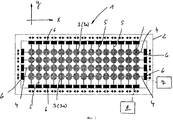
фиг.1 - в упрощенном схематичном изображении вид сверху устройства суппорта или крестового суппорта упаковочной головки в соответствии с изобретением,figure 1 is a simplified schematic representation of a top view of the device of the caliper or cross support of the packaging head in accordance with the invention,
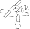
фиг.2 - в перспективном детальном изображении крестовой суппорт устройства крестового суппорта в соответствии с фиг.1 совместно с предусмотренным на крестовом суппорте упаковочным патроном,figure 2 is a perspective detailed image of a cross caliper device cross caliper in accordance with figure 1 together with provided on the cross caliper packing cartridge,
фиг.3 и 4 - в положениях а) и b) различные формообразования групп сосудов для облегчения принципа работы упаковочной головки в соответствии с фиг.1 и 2,figure 3 and 4 - in positions a) and b) various shaping groups of vessels to facilitate the principle of operation of the packaging head in accordance with figures 1 and 2,
фиг.5 - в упрощенном изображении на виде сверху крестовой суппорт другого варианта осуществления упаковочной головки в соответствии с изобретением,5 is a simplified top view of the cross support of another embodiment of the packaging head in accordance with the invention,
фиг.6 - в положениях а) и b различные формообразования групп сосудов для облегчения принципа работы упаковочной головки с крестовым суппортом в соответствии с фиг.5.6 - in positions a) and b, various forming groups of vessels to facilitate the principle of operation of the packaging head with a cross slide in accordance with figure 5.
Для лучшего понимания три проходящие перпендикулярно друг другу оси: горизонтальная ось X, горизонтальная ось Y и вертикальная ось Z обозначены на фигурах соответственно как оси X, Y и Z.For a better understanding, three axes running perpendicular to each other: the horizontal axis X, the horizontal axis Y and the vertical axis Z are indicated in the figures respectively as the axes X, Y and Z.
На фигурах позицией 1 обозначена упаковочная головка не представленной более детально установки для перемещения групп сосудов или бутылок из положения приемки или из приемной зоны в положение складирования или в зону складирования, к примеру, для выемки из ящика поданных в многорукавном потоке или по дорожкам по транспортеру в положение складирования бутылок F в виде группы бутылок и загрузки этой группы бутылок на транспортер.In the figures,
Упаковочная головка 1 состоит, в основном, из рамы 2 с большим количеством приемных мест или крестовых суппортов 3 и из множества стержнеобразных направляющих и исполнительных элементов 4 и 5, из которых расположенные параллельно друг другу и на расстоянии друг от друга направляющие и исполнительные элементы 4 своими осями ориентированы, соответственно, в горизонтальном направлении, то есть по оси X, а расположенные также параллельно друг другу и отстоящие друг от друга направляющие и исполнительные элементы 5 своими осями ориентированы в горизонтальном направлении и перпендикулярно направляющим и исполнительным элементам 4, то есть по оси Y.The
В представленном варианте осуществления изобретения все направляющие и исполнительные элементы 4 расположены далее своими осями, по меньшей мере, в одной горизонтальной плоскости (плоскость X-Y), и все направляющие и исполнительные элементы 5 расположены своими осями также, по меньшей мере, в одной горизонтальной плоскости (плоскость X-Y), правда, выше направляющих и исполнительных элементов 4.In the presented embodiment of the invention, all the guide and actuating
Все направляющие и исполнительные элементы 4 и 5 удерживаются далее своими концами, соответственно, в ползунах 6, которые со своей стороны проведены на раме 2 с возможностью перемещения перпендикулярно продольному расположению соответствующих направляющих и исполнительных элементов 4 или 5, как это изображено посредством двойных стрелок на фиг.1.All the guiding and actuating
В каждой точке пересечения двух направляющих и исполнительных элементов 4, 5 предусмотрен крестовой суппорт 3, который проведен по этим направляющим и исполнительным элементам 4 и 5 с возможностью перемещения.At each point of intersection of the two guides and
За счет расположения крестовых суппортов 3 в точках пересечения направляющих и исполнительных элементов 4 или 5 крестовые суппорты 3 располагаются в нескольких проходящих в направлении оси Х рядах, то есть на изображении в соответствии с фиг.1 в общей сложности в четырех таких рядах, и в нескольких проходящих, соответственно, по оси Y зазорах, то есть на изображении в соответствии с фиг.1 в общей сложности в пятнадцати зазорах.Due to the location of the
К направляющим и исполнительным элементам 4 на раме 2 присоединен, по меньшей мере, один исполнительный привод, обозначенный на фиг.1 блоком 7. Посредством соответствующего приведения в действие или настройки исполнительного привода 7 направляющие и исполнительные элементы 4 с регулировкой перпендикулярно их продольному расположению, то есть по оси Y, могут регулироваться или перемещаться и при том, к примеру, таким образом, что расстояние между соседними направляющими и исполнительными элементами 4, а тем самым и расстояние между примыкающими друг к другу в направлении оси Y крестовыми суппортами 3 может изменяться равнозначным образом и, соответственно, одним и тем же или же различным путем, однако, к примеру, с условием принципиального сохранения симметрии расположения крестовых суппортов относительно расположенной в плоскости X-Y средней плоскости рамы.At least one actuator drive is indicated on the guides and
К направляющим и исполнительным элементам 5 присоединен также, по меньшей мере, один изображенный на фиг.1 посредством блока 8 исполнительный привод. Посредством соответствующего приведения в действие или настройки исполнительного привода 8 направляющие и исполнительные элементы 5 с регулировкой перпендикулярно их продольному расположению, то есть по оси X, могут регулироваться или перемещаться и при том, к примеру, опять же таким образом, что расстояние между соседними направляющими и исполнительными элементами 5, а тем самым и расстояние между примыкающими друг к другу в направлении оси Х крестовыми суппортами 3 может изменяться равнозначным образом и, соответственно, одним и тем же или же различным путем, однако, к примеру, с условием принципиального сохранения симметрии расположения крестовых суппортов относительно расположенной в плоскости Y-Z средней плоскости рамы.At least one actuator shown in FIG. 1 by means of
На каждом крестовом суппорте 3 предусмотрен захват для сосудов в форме упаковочного патрона 9, который выступает за нижнюю часть крестового суппорта 3 в направлении оси Z и при помощи которого бутылка F может быть, соответственно, захвачена в зоне ее горловины.On each
С помощью упаковочной головки 1, которая в процессе практической эксплуатации предусмотрена на подъемном и транспортирующем устройстве для регулируемого возвратно-поступательного движения в вертикальном направлении, то есть по оси Z, а также для регулируемого транспортирующего движения по горизонтальной оси, к примеру по оси Y, возможно осуществление различных производственных или рабочих приемов.Using the
Фиг.3 демонстрирует процесс использования упаковочной головки 1 для загрузки групп бутылок в ящики для бутылок. В соответствии с положением а) на фиг.3 бутылки F подаются по транспортеру к приемной зоне или к упаковочному столу 10, на котором бутылки F стоят в положении готовности в нескольких ориентированных в направлении оси X рядах или дорожках, причем в представленном варианте осуществления изобретения в четырех рядах или дорожках, соответственно, с пятнадцатью бутылками F и, таким образом, что бутылки F по оси Y образуют пятнадцать зазоров с четырьмя непосредственно смежными друг с другом бутылками F.Figure 3 shows the process of using the
Эта стоящая в положении готовности на упаковочном столе 10 группа бутылок захватывается упаковочной головкой 1 или ее упаковочным патроном 9, а после снятия с упаковочного стола 10 посредством регулируемой настройки направляющих и исполнительных элементов 4 и 5 формируется заново перпендикулярно их продольному расположению, так что бутылки F образуют затем положение b), соответственно, для загрузки в три ящика для бутылок трех групп 11 бутылок, в которых, соответственно, в четырех ориентированных по оси X рядах бутылки F плотно прилегают друг к другу, и эти ряды бутылок в направлении оси Y находятся на расстоянии друг от друга.This group of bottles standing in the standby position on the packing table 10 is gripped by the
Фиг.4 демонстрирует в положениях а) и b) другой принцип работы, при котором на упаковочном столе 10 из поданных по транспортеру бутылок F образуются три ряда, соответственно, в отдельных дорожках и при том таким образом, что бутылки F в каждом ряду плотно прилегают друг к другу, и каждая бутылка в ряду в направлении оси Y на расстоянии соседствует с бутылкой F другого ряда, то есть бутылки F в этой группе снова располагаются в ориентированных перпендикулярно друг другу рядах и зазорах.Figure 4 demonstrates in positions a) and b) another principle of operation in which three rows are formed on the packing table 10 from bottles F fed through the conveyor, respectively, in separate paths and in such a way that the bottles F in each row fit snugly to each other, and each bottle in a row in the direction of the Y axis is adjacent to a bottle F of another row, that is, bottles F in this group are again arranged in rows and gaps oriented perpendicular to each other.
Из сформированной на упаковочном столе 10 группы бутылок посредством индивидуально управляемых упаковочных патронов 9 упаковочной головки 1 захватываются и снимаются лишь заштрихованные в положении а) бутылки F. После снятия группы бутылок посредством соответствующей настройки направляющих и исполнительных элементов 4 и 5, а тем самым и крестовых суппортов 3 формируются две группы 12 бутылок, соответственно, с тремя ориентированными в направлении оси Х рядами, из которых оба внешних ряда имеют, соответственно, по три бутылки F, а центральный ряд лишь две бутылки F, которые по отношению к бутылкам F внешних рядов смещены на расстояние, равное зазору между ними. Это достигается посредством соответствующей регулировки направляющих и исполнительных элементов 5 в плане уменьшения зазора между крестовыми суппортами 3 для каждой группы 12 бутылок по оси X, а также посредством соответствующей регулировки направляющих и исполнительных элементов 4 в плане уменьшения зазора между крестовыми суппортами 3 по оси Y.From the bottle group formed on the packing table 10, by means of individually controlled
Ранее исходили из того, что упаковочная головка 1 служит для захвата бутылок F в виде группы бутылок с упаковочного стола 10 (приемная зона) и для загрузки бутылок F в виде группы 11 или 12 бутылок в ящики для бутылок (зона складирования). Само собой разумеется, что упаковочная головка 1 может аналогичным образом служить и, наоборот, для выемки бутылок F из ящиков заданной, к примеру, формой ящика группой бутылок и для загрузки бутылок в виде трансформированной группы на транспортер или на упаковочный стол 10 для бутылок.Previously, it was assumed that the
За счет расположения крестовых суппортов 3 на направляющих и исполнительных элементах 4 и 5 в варианте осуществления изобретения в соответствии с фиг.1, в принципе, возможно регулировать все предусмотренные на соответствующем направляющем элементе 4 или 5 крестовые суппорты, а тем самым, и относящиеся к ним упаковочные патроны 9 совместно по оси Х (посредством регулировки соответствующего направляющего и исполнительного элемента 5) или по оси Y (посредством регулировки соответствующего направляющего и исполнительного элемента 4).Due to the location of the
Фиг.5 демонстрирует в очень схематичном изображении на виде сверху крестовой суппорт 3а упаковочной головки, который (крестовой суппорт 3а) в отношении трансформации удерживаемых в упаковочной головке групп бутылок имеет повышенную степень свободы и при том за счет того, что упаковочная головка предусмотрена с возможностью управляемой регулировки или перемещения относительно захватывающего ее крестового суппорта 3а в плоскости X-Y и при том, к примеру, на вспомогательном суппорте 13, который с помощью независимого исполнительного привода может линейно регулироваться в этой плоскости, к примеру, по оси X. В принципе, регулировка упаковочного патрона 9 относительно крестового суппорта 3а может производиться также и посредством вращательного или поворотного движения. Упаковочная головка выполнена в этом случае таким образом, что лишь некоторые крестовые суппорты выполнены как крестовые суппорты 3а с дополнительной возможностью регулировки или с дополнительной осью регулировки для упаковочного патрона 9, к примеру, некоторые крестовые суппорты каждого второго расположенного по оси X ряда суппортов. К примеру, в упаковочной головке с тремя рядами расположенных в направлении оси Х крестовых суппортов тогда лишь центральный ряд имеет крестовые суппорты 3а, в то время как внешние ряды образованы посредством крестовых суппортов 3. И в центральном ряду тогда, к примеру, лишь каждый второй крестовой суппорт является крестовым суппортом 3а с дополнительной осью регулировки для упаковочного патрона 9, в то время как, впрочем, и в центральном ряду упаковочной головки или устройства крестового суппорта используются крестовые суппорты 3.Fig. 5 shows in a very schematic top view a
Фиг.6 демонстрирует возможный принцип работы частично снабженной крестовыми суппортами 3а упаковочной головки. На упаковочном столе 10 бутылки F опять находятся в положении готовности в виде группы бутылок, которая имеет три сформированных, соответственно, в отдельных дорожках и ориентированных по оси X ряда бутылок и в которой с каждой бутылкой в ряду по оси Y соседствует бутылка другого ряда; бутылки F располагаются таким образом на упаковочном столе 10 в виде группы с несколькими расположенными по оси Х рядами и с несколькими расположенными по оси Y зазорами. Посредством упаковочной головки или посредством индивидуально управляемого упаковочного патрона этой упаковочной головки захватываются в таком случае лишь отмеченные штриховкой в положении а) бутылки F и при том, соответственно, три бутылки F каждого внешнего ряда и две бутылки F центрального ряда, которые (бутылки) в этом центральном ряду располагаются относительно друг друга на расстоянии, равном двойному зазору между бутылками. После снятия бутылок F с упаковочного стола 10 производится трансформирование захваченной состоящей в общей сложности из восьми бутылок F группы бутылок таким образом, что группа 14 бутылок после снятия снова имеет два внешних ряда, ориентированных по оси X, соответственно, с тремя бутылками F, и центральный ряд, также ориентированный по оси X, правда, лишь с двумя бутылками F, которые по сравнению с бутылками внешних рядов смещены на расстояние, равное зазору между ними. Это новое формообразование группы 14 бутылок достигается посредством того, что бутылки F центрального ряда удерживаются на крестовых суппортах 3а, с помощью которых дополнительно к общей регулировке крестовых суппортов посредством направляющих и исполнительных элементов 4 и 5 возможна индивидуальная регулировка упаковочных патронов 9 по оси X.6 shows a possible principle of operation of a packaging head partially provided with
Изобретение было описано ранее на примерах осуществления. При этом понимается, что возможны многочисленные изменения, а также преобразования без потери вследствие этого изобретательской идеи, лежащей в основе изобретения.The invention has been described previously with examples of implementation. It is understood that numerous changes are possible, as well as transformations without loss due to this inventive idea underlying the invention.
Перечень ссылочных позицийList of Reference Items
1 - упаковочная головка;1 - packing head;
2 - рама упаковочной головки;2 - the frame of the packaging head;
3, 3а - крестовой суппорт;3, 3a - cross support;
4, 5 - направляющие и исполнительные элементы;4, 5 - guides and actuators;
6 - ползун;6 - slider;
7, 8 - исполнительный привод;7, 8 - executive drive;
9 - упаковочный патрон или захват для бутылок F;9 - a packing cartridge or a gripper for bottles F;
10 - упаковочный стол;10 - packing table;
11, 12 - группа бутылок;11, 12 - a group of bottles;
13 - вспомогательный суппорт;13 - auxiliary support;
14 - группа бутылок;14 - a group of bottles;
F - бутылка;F is a bottle;
Х - ось Х;X - axis X;
Y - ось Y;Y - axis Y;
Z - ось Z.Z - axis Z.
Claims (10)
Applications Claiming Priority (2)
| Application Number | Priority Date | Filing Date | Title |
|---|---|---|---|
| DE102007039850.8A DE102007039850B4 (en) | 2007-08-23 | 2007-08-23 | packers head |
| DE102007039850.8 | 2007-08-23 |
Publications (1)
| Publication Number | Publication Date |
|---|---|
| RU2424960C1 true RU2424960C1 (en) | 2011-07-27 |
Family
ID=39929806
Family Applications (1)
| Application Number | Title | Priority Date | Filing Date |
|---|---|---|---|
| RU2010110820/21A RU2424960C1 (en) | 2007-08-23 | 2008-07-25 | Packing head |
Country Status (11)
| Country | Link |
|---|---|
| US (1) | US8286409B2 (en) |
| EP (1) | EP2183162B1 (en) |
| JP (1) | JP5547072B2 (en) |
| CN (1) | CN101808904B (en) |
| AT (1) | ATE508948T1 (en) |
| BR (1) | BRPI0815271A2 (en) |
| DE (1) | DE102007039850B4 (en) |
| MX (1) | MX2010001968A (en) |
| PL (1) | PL2183162T3 (en) |
| RU (1) | RU2424960C1 (en) |
| WO (1) | WO2009024246A1 (en) |
Families Citing this family (32)
| Publication number | Priority date | Publication date | Assignee | Title |
|---|---|---|---|---|
| US8915692B2 (en) | 2008-02-21 | 2014-12-23 | Harvest Automation, Inc. | Adaptable container handling system |
| US8931240B2 (en) | 2008-10-27 | 2015-01-13 | Formax, Inc. | Shuttle system and method for moving food products into packaging |
| DE102009043981A1 (en) * | 2009-09-11 | 2011-03-17 | Krones Ag | Apparatus and method for packaging a plurality of articles, forming unit |
| US8594833B2 (en) * | 2010-10-29 | 2013-11-26 | Pearson Packaging Systems | Programmable product picking apparatus |
| US9147173B2 (en) | 2011-10-31 | 2015-09-29 | Harvest Automation, Inc. | Methods and systems for automated transportation of items between variable endpoints |
| US8676425B2 (en) | 2011-11-02 | 2014-03-18 | Harvest Automation, Inc. | Methods and systems for maintenance and other processing of container-grown plants using autonomous mobile robots |
| DE102011087052A1 (en) * | 2011-11-24 | 2013-05-29 | Krones Ag | Device and method for handling containers |
| DE202012100153U1 (en) * | 2012-01-17 | 2012-02-23 | Sommer Anlagentechnik Gmbh | Device for gripping and separating components |
| US8937410B2 (en) | 2012-01-17 | 2015-01-20 | Harvest Automation, Inc. | Emergency stop method and system for autonomous mobile robots |
| DE202013105022U1 (en) * | 2012-11-12 | 2014-02-18 | Federspiel Maschinenbau Gmbh | gripper head |
| US9365366B2 (en) * | 2013-06-24 | 2016-06-14 | Intelligrated Headquarters Llc | Robotic container reorganizer |
| DE102013107574A1 (en) | 2013-07-16 | 2015-01-22 | Khs Gmbh | Process for the production of containers |
| DE102013111088A1 (en) * | 2013-10-07 | 2015-04-09 | Krones Aktiengesellschaft | Method and system for discharging on a horizontal conveyor continuously moving and guided in parallel rows beverage containers |
| DE102013113325A1 (en) | 2013-12-02 | 2015-06-03 | Krones Aktiengesellschaft | Method and device for testing adhesions between articles of a container |
| EP2878544B2 (en) | 2013-12-02 | 2023-01-11 | Krones Aktiengesellschaft | Method and device for testing adhesive joints between articles a container |
| DE102014221233A1 (en) | 2014-10-20 | 2016-04-21 | Krones Aktiengesellschaft | Device and method for handling articles |
| DE102014221218A1 (en) | 2014-10-20 | 2016-04-21 | Krones Aktiengesellschaft | Device and method for handling articles |
| JP6382132B2 (en) * | 2015-03-04 | 2018-08-29 | Towa株式会社 | Cutting device, conveying method, conveying program, and recording medium storing conveying program |
| JP6320323B2 (en) * | 2015-03-04 | 2018-05-09 | Towa株式会社 | Manufacturing apparatus, conveying method, conveying program, and recording medium storing conveying program |
| JP6382133B2 (en) * | 2015-03-04 | 2018-08-29 | Towa株式会社 | Cutting device, conveying method, conveying program, and recording medium storing conveying program |
| CN105059926A (en) * | 2015-07-31 | 2015-11-18 | 重庆市鑫圣陶瓷有限公司 | Transfer separation device for ceramic tiles |
| CN105107753B (en) * | 2015-08-14 | 2018-03-02 | 临海市劳尔机械有限公司 | A kind of automatic eyeglass sorting machine |
| CN105149244B (en) * | 2015-09-09 | 2017-12-29 | 临海市锦铮机械有限公司 | Eyeglass detection, stepping, the intelligent all-in-one of storage |
| CN105584676B (en) * | 2016-02-03 | 2019-04-05 | 广东粤东机械实业有限公司 | Fill the plastic cup automatic arranging mechanism of production line |
| CN107031906B (en) * | 2017-01-23 | 2019-04-26 | 浙江智霖机械有限公司 | A kind of recrater gripper |
| DE102018115522A1 (en) * | 2018-06-27 | 2020-01-02 | Krones Aktiengesellschaft | Handling and / or unpacking device and method for unpacking articles |
| DE102018115521A1 (en) * | 2018-06-27 | 2020-01-02 | Krones Aktiengesellschaft | Handling and / or packaging device and method for packaging articles |
| DE102018119575A1 (en) * | 2018-08-13 | 2020-02-13 | Krones Aktiengesellschaft | Process for transferring and inserting articles in outer packaging and device for carrying out the process |
| CN110155716A (en) * | 2019-06-17 | 2019-08-23 | 深圳市美卡达科技有限公司 | A kind of XY twocouese automatic adjustable-pitch device |
| DE102021132681A1 (en) | 2021-12-10 | 2023-06-15 | Ma Micro Automation Gmbh | Handling device for changing the grid dimensions of a grid arrangement of workpieces |
| CN114604607B (en) * | 2022-03-30 | 2024-05-17 | 重庆犇沃机电有限公司 | Automatic separating and pasting integrated machine for mouse foot pad |
| DE102022124595A1 (en) | 2022-09-26 | 2024-03-28 | Khs Gmbh | Packing head and method for packing or unpacking containers |
Family Cites Families (28)
| Publication number | Priority date | Publication date | Assignee | Title |
|---|---|---|---|---|
| US2308209A (en) * | 1941-03-11 | 1943-01-12 | Hoffman Beverage Company | Article transferring apparatus |
| GB999282A (en) * | 1963-02-09 | 1965-07-21 | Dawson Bros Ltd | Improvements relating to machines for loading bottles into cartons, boxes or the like |
| US3300945A (en) * | 1963-09-24 | 1967-01-31 | Alto Co | Method and apparatus for packaging |
| DE1928397A1 (en) * | 1969-06-04 | 1970-12-10 | Certus Maschb Gmbh | Gripper head for a bottle reloading device |
| US3648427A (en) * | 1970-08-11 | 1972-03-14 | Emhart Corp | Apparatus for loading frangible containers |
| US3780492A (en) * | 1971-02-05 | 1973-12-25 | A C I Operations | Apparatus for packing bottles, jars or like into cases |
| US3843316A (en) * | 1971-12-20 | 1974-10-22 | Owens Illinois Inc | Machine for producing a plastic-covered glass container |
| US3842570A (en) * | 1973-01-19 | 1974-10-22 | Monaghan Automated Syst Inc | High speed tray former and loader |
| DK152906C (en) * | 1976-11-12 | 1988-12-05 | Hamba Maschf | DEVICE FOR DRAINING FOOD AND FOODS, SPECIFICALLY MILK PRODUCTS, IN BASKET SINGLE CONTAINERS |
| DE2757516C2 (en) * | 1977-12-23 | 1984-03-15 | Seitz Enzinger Noll Maschinenbau Ag, 6800 Mannheim | Bottle holder frame for the simultaneous transfer and insertion in bundles of bottles and the like that have been piled up in rows parallel to the conveying direction. In crates, crates, crates and the like. |
| DE2900584C2 (en) * | 1979-01-09 | 1985-03-07 | Seitz Enzinger Noll Maschinenbau Ag, 6800 Mannheim | Bottle holder frame for bundling and inserting bottles and the like. In boxes and the like. |
| NL8304111A (en) * | 1983-11-30 | 1985-06-17 | Stork Bepak Bv | Bottle handling gripper frame - has four spaced gripper heads in one direction, and three spaced gripper heads at right angles to first |
| ES2005327A6 (en) * | 1987-09-16 | 1989-03-01 | Paniagua Olaechea Rosalina | Process for the automated placing of fruit in packing cases and the corresponding machinery |
| JPH03229338A (en) * | 1990-02-05 | 1991-10-11 | Matsushita Electron Corp | Rom testing method |
| DE9101063U1 (en) * | 1991-01-31 | 1991-04-18 | Rico-Maschinenbau Max Appel KG, 7080 Aalen | Gripping device for bottles or similar containers to be placed together in a box or similar or to be removed from it |
| JP3229338B2 (en) * | 1991-05-28 | 2001-11-19 | 株式会社マキ製作所 | Article arrangement device and box packing device |
| IT1271481B (en) * | 1993-10-11 | 1997-05-28 | Vortex Systems Srl | PRODUCT HANDLING DEVICE AND RELATED EQUIPMENT |
| JP3520537B2 (en) * | 1993-10-22 | 2004-04-19 | 澁谷工業株式会社 | Caser / Uncercer spacing adjustment device |
| JP3660707B2 (en) * | 1995-02-17 | 2005-06-15 | 株式会社マキ製作所 | Method and apparatus for sorting fruits and vegetables |
| US5851042A (en) * | 1997-01-09 | 1998-12-22 | Bankuty; Geza E. | Collet for gripping container caps |
| JPH115133A (en) * | 1997-06-12 | 1999-01-12 | Toyotomi Kiko Kk | Composite type article carrier |
| DE10210353A1 (en) * | 2002-03-08 | 2003-09-18 | Friesisches Brauhaus Zu Jever | Process for transferring bottles comprises moving pack tulips toward each other after receiving the bottles and before insertion of the bottles in packaging |
| CN2564479Y (en) * | 2002-04-10 | 2003-08-06 | 房牛宝 | Arrangement mechanism for automatic multi-bottle box packing machine |
| ITBO20020460A1 (en) * | 2002-07-18 | 2004-01-19 | Aetna Group Spa | DEVICE FOR THE SEPARATION OF GROUPS OF CONTINUOUSLY SUPPLIED PRODUCTS |
| JP4124205B2 (en) * | 2004-04-26 | 2008-07-23 | ダイキン工業株式会社 | Preheating operation method and apparatus for inverter-driven compressor |
| DE102004047826B4 (en) * | 2004-09-29 | 2012-04-26 | Rst Roboter-System-Technik Gmbh | Method for transferring bottles and device for carrying out the method |
| DE102005039842A1 (en) * | 2005-08-23 | 2007-03-01 | Khs Ag | Process for producing mixed containers, and apparatus for carrying out the method |
| ITRE20060053A1 (en) * | 2006-04-28 | 2007-10-29 | A C M I Spa | SELF-REGULATING CENTERING DEVICE |
-
2007
- 2007-08-23 DE DE102007039850.8A patent/DE102007039850B4/en not_active Expired - Fee Related
-
2008
- 2008-07-25 WO PCT/EP2008/006114 patent/WO2009024246A1/en active Application Filing
- 2008-07-25 PL PL08785067T patent/PL2183162T3/en unknown
- 2008-07-25 BR BRPI0815271-3A2A patent/BRPI0815271A2/en active IP Right Grant
- 2008-07-25 MX MX2010001968A patent/MX2010001968A/en active IP Right Grant
- 2008-07-25 CN CN2008801083466A patent/CN101808904B/en active Active
- 2008-07-25 RU RU2010110820/21A patent/RU2424960C1/en not_active IP Right Cessation
- 2008-07-25 AT AT08785067T patent/ATE508948T1/en active
- 2008-07-25 EP EP08785067A patent/EP2183162B1/en active Active
- 2008-07-25 JP JP2010521332A patent/JP5547072B2/en not_active Expired - Fee Related
-
2010
- 2010-02-23 US US12/710,956 patent/US8286409B2/en active Active
Also Published As
| Publication number | Publication date |
|---|---|
| EP2183162B1 (en) | 2011-05-11 |
| BRPI0815271A2 (en) | 2015-02-03 |
| CN101808904A (en) | 2010-08-18 |
| CN101808904B (en) | 2012-11-28 |
| PL2183162T3 (en) | 2011-08-31 |
| US8286409B2 (en) | 2012-10-16 |
| US20100212265A1 (en) | 2010-08-26 |
| DE102007039850B4 (en) | 2016-09-15 |
| EP2183162A1 (en) | 2010-05-12 |
| JP2010536684A (en) | 2010-12-02 |
| DE102007039850A1 (en) | 2009-02-26 |
| WO2009024246A1 (en) | 2009-02-26 |
| ATE508948T1 (en) | 2011-05-15 |
| JP5547072B2 (en) | 2014-07-09 |
| MX2010001968A (en) | 2010-03-11 |
Similar Documents
| Publication | Publication Date | Title |
|---|---|---|
| RU2424960C1 (en) | Packing head | |
| US10442638B2 (en) | Method and apparatus for conveying articles, piece goods and/or bundles within at least two conveying path sections | |
| US20170203865A1 (en) | Apparatus and methods for transferring continuously moving articles to continuously moving packages with intervening article grouping and group pitch adjustment | |
| RU2714068C2 (en) | Fiber laying machine | |
| DE102012219886A1 (en) | Handling device of a conveyor section for article promotion and method for controlling such a handling device | |
| KR20110029137A (en) | Packaging machine and method of packaging articles | |
| JPWO2005035165A1 (en) | Work transfer device for press machine | |
| WO2014072518A2 (en) | Gripper head | |
| ITPR20090059A1 (en) | APPARATUS, SYSTEM AND METHOD TO MANIPULATE A PACKAGE | |
| EP2546153A1 (en) | Device and method for stacking stackable pieces | |
| CN103029984A (en) | System for automatically loading injection bottles into disc and mechanical gripping hand thereof | |
| US10058964B2 (en) | Transport device for transporting a work piece along consecutive processing stations of a production installation, a production installation, a multistage forming press, and a method for manufacturing products from work pieces by means of a production installation | |
| IT202000008080A1 (en) | HANDLING HEAD FOR OBJECTS | |
| DE102018132329A1 (en) | Handling and / or packaging device and method for repackaging article groups | |
| JP4604013B2 (en) | Work transfer device for press machine | |
| US10322834B2 (en) | Positioning and transfer of products | |
| JP5056151B2 (en) | Goods transfer device | |
| JP6671119B2 (en) | Work transfer device | |
| US20220288727A1 (en) | Method for transporting workpiece parts | |
| US20220379532A1 (en) | Method for Handling Individual Parts, Handling Systems, and Grouping Unit | |
| DE102017118928A1 (en) | Layer forming and palletizing module and method for grouping and palletizing piece goods | |
| JP2018111522A (en) | Article boxing apparatus | |
| JP7244730B2 (en) | Article stacking device | |
| JP2003089421A (en) | Method and device for stacking group of vessels | |
| CN214003305U (en) | Handling equipment and snatch frock |
Legal Events
| Date | Code | Title | Description |
|---|---|---|---|
| PD4A | Correction of name of patent owner | ||
| MM4A | The patent is invalid due to non-payment of fees |
Effective date: 20180726 |