RU2294271C1 - Materials and coating joining method - Google Patents
Materials and coating joining method Download PDFInfo
- Publication number
- RU2294271C1 RU2294271C1 RU2005125966/02A RU2005125966A RU2294271C1 RU 2294271 C1 RU2294271 C1 RU 2294271C1 RU 2005125966/02 A RU2005125966/02 A RU 2005125966/02A RU 2005125966 A RU2005125966 A RU 2005125966A RU 2294271 C1 RU2294271 C1 RU 2294271C1
- Authority
- RU
- Russia
- Prior art keywords
- coating
- layer
- layers
- parts
- protrusions
- Prior art date
Links
- 238000000576 coating method Methods 0.000 title claims abstract description 45
- 239000011248 coating agent Substances 0.000 title claims abstract description 44
- 238000000034 method Methods 0.000 title claims abstract description 29
- 239000000463 material Substances 0.000 title claims abstract description 27
- 238000005304 joining Methods 0.000 title description 3
- 238000003466 welding Methods 0.000 claims abstract description 30
- 239000010410 layer Substances 0.000 claims description 32
- 239000011247 coating layer Substances 0.000 claims description 17
- 229920001169 thermoplastic Polymers 0.000 claims description 5
- 239000004416 thermosoftening plastic Substances 0.000 claims description 5
- 230000007797 corrosion Effects 0.000 abstract description 6
- 238000005260 corrosion Methods 0.000 abstract description 6
- 230000000694 effects Effects 0.000 abstract description 4
- 238000010438 heat treatment Methods 0.000 abstract description 2
- 239000000126 substance Substances 0.000 abstract description 2
- 239000011324 bead Substances 0.000 abstract 4
- 239000002320 enamel (paints) Substances 0.000 description 6
- 229910000831 Steel Inorganic materials 0.000 description 3
- 238000005253 cladding Methods 0.000 description 3
- 230000006835 compression Effects 0.000 description 3
- 238000007906 compression Methods 0.000 description 3
- 239000011521 glass Substances 0.000 description 3
- 238000004519 manufacturing process Methods 0.000 description 3
- 238000002844 melting Methods 0.000 description 3
- 239000011253 protective coating Substances 0.000 description 3
- 239000010959 steel Substances 0.000 description 3
- 239000002131 composite material Substances 0.000 description 2
- 238000010586 diagram Methods 0.000 description 2
- 230000004927 fusion Effects 0.000 description 2
- 239000002184 metal Substances 0.000 description 2
- 239000006223 plastic coating Substances 0.000 description 2
- 230000001681 protective effect Effects 0.000 description 2
- 238000007789 sealing Methods 0.000 description 2
- 238000004125 X-ray microanalysis Methods 0.000 description 1
- 230000002411 adverse Effects 0.000 description 1
- 238000004458 analytical method Methods 0.000 description 1
- 239000010953 base metal Substances 0.000 description 1
- 230000015572 biosynthetic process Effects 0.000 description 1
- 230000007547 defect Effects 0.000 description 1
- 239000007789 gas Substances 0.000 description 1
- 230000003993 interaction Effects 0.000 description 1
- 239000000203 mixture Substances 0.000 description 1
- 230000003647 oxidation Effects 0.000 description 1
- 238000007254 oxidation reaction Methods 0.000 description 1
- 239000002245 particle Substances 0.000 description 1
- 239000004033 plastic Substances 0.000 description 1
- 229920000642 polymer Polymers 0.000 description 1
- 238000002360 preparation method Methods 0.000 description 1
- 238000003908 quality control method Methods 0.000 description 1
- 238000000926 separation method Methods 0.000 description 1
- 239000002002 slurry Substances 0.000 description 1
- 239000007787 solid Substances 0.000 description 1
- 230000003595 spectral effect Effects 0.000 description 1
- 238000010183 spectrum analysis Methods 0.000 description 1
- 239000000725 suspension Substances 0.000 description 1
- 239000012815 thermoplastic material Substances 0.000 description 1
- 230000008719 thickening Effects 0.000 description 1
Images

Landscapes
- Application Of Or Painting With Fluid Materials (AREA)
Abstract
Description
Заявляемое изобретение относится к сварке, а именно к способам защиты внутренней поверхности сварного шва от коррозионного воздействия агрессивной среды, когда детали корпуса имеют внутренее, многослойное защитное покрытие, содержащее хрупкие слои.The invention relates to welding, and in particular to methods of protecting the inner surface of a weld from the corrosive effects of an aggressive environment, when the body parts have an internal, multilayer protective coating containing brittle layers.
Изобретение может быть использовано при изготовлении корпусов и труб, доступ к внутренней поверхности которых после сварки затруднен, а для защиты внутренней поверхности от коррозионного воздействия агрессивной среды используют непластичное покрытие, в частности эмалевое покрытие на трубах или оксидное покрытие на корпусах изложниц, многослойных защитных контейнерах для заливки расплавленного металла.The invention can be used in the manufacture of casings and pipes, access to the inner surface of which is difficult after welding, and to protect the inner surface from the corrosive effects of an aggressive environment, a non-plastic coating is used, in particular an enamel coating on pipes or an oxide coating on the mold bodies, multilayer protective containers for pouring molten metal.
Известен способ сварки труб с покрытием, при котором на трубах с внутренним эмалевым покрытием, при котором на трубах в зоне стыка образуют теплоизолирующую прослойку между зоной сварки и внутренней поверхностью трубы. Эмалевое покрытие наносят на внутреннюю поверхность, производят сборку под сварку и сварку труб между собой. Теплоизолирующую прослойку образуют из материала труб путем формирования на свариваемых кромках замкового соединения, эмалевое покрытие наносят и на торцы замка. После сборки зону стыка нагревают до температуры оплавления эмалевого покрытия с одновременным сжатием торцов замка, формируя монолитный слой покрытия на внутренней поверхности труб. Способ защищен а.с. №1479249, МКИ В 23 К 31/06, опубл. 1989 г.A known method of welding pipes with a coating, in which pipes with an internal enamel coating, in which pipes in the joint zone form a heat-insulating layer between the welding zone and the inner surface of the pipe. The enamel coating is applied to the inner surface, assembly is performed for welding and welding of pipes between themselves. A heat-insulating layer is formed from the material of the pipes by forming a welded joint on the edges of the welded joint, an enamel coating is also applied to the ends of the castle. After assembly, the joint zone is heated to the reflow temperature of the enamel coating with simultaneous compression of the ends of the lock, forming a monolithic coating layer on the inner surface of the pipes. The method is protected A.S. No. 1479249, MKI B 23 K 31/06, publ. 1989 year
Недостатком данного способа является то, что реализация его возможна только на деталях, толщина которых значительна, когда при изготовлении замкового соединения есть возможность обеспечить сжатие без потери устойчивости конструкции, а формирование утолщения не препятствует дальнейшей сборке и не ограничено допусками на детали, устанавливаемые снаружи. Кроме того, окисление материала кромок во время нагрева при оплавлении эмалевого покрытия отрицательно влияет на качество сварного соединения.The disadvantage of this method is that its implementation is possible only on parts whose thickness is significant, when in the manufacture of the castle joints it is possible to provide compression without loss of structural stability, and the formation of a thickening does not prevent further assembly and is not limited by tolerances on parts installed externally. In addition, the oxidation of the material of the edges during heating during reflow of the enamel coating adversely affects the quality of the welded joint.
Наиболее близким к заявляемому по технической сущности является решение, описанное в а.с. №1570870, МКИ В 23 К 31/00, опубл. 1990 г., защищающее способ соединения плакированных материалов. В способе перед сваркой часть плакирующего покрытия, примыкающего к сварному шву, удаляют, создавая зону корпуса без покрытия, кромки основного металла, свободные от покрытия, отгибают. Сборку осуществляют до плотного контакта как поверхностей деталей без покрытия, так и поверхностей деталей, содержащих покрытие, а затем сваривают одновременно одним источником нагрева. Данный способ выбран в качестве прототипа заявляемого изобретения.Closest to the claimed technical essence is the solution described in A.S. No. 1570870, MKI B 23 K 31/00, publ. 1990, protecting method for joining clad materials. In the method, before welding, part of the cladding coating adjacent to the weld is removed, creating a zone of the body without coating, the edges of the base metal, free from coating, are bent. The assembly is carried out until the surfaces of the uncoated parts are tightly contacted, and the surfaces of the parts containing the coating, and then they are welded simultaneously with one heat source. This method is selected as a prototype of the claimed invention.
Способ пригоден лишь при использовании материалов с пластичным плакирующим покрытием на полимерной основе, условия эксплуатации которых ограничены, в частности они не пригодны для эксплуатации при контакте с суспензиями, содержащими твердые частицы, при повышенных температурах и др.The method is suitable only when using materials with a plastic cladding coating on a polymer basis, the operating conditions of which are limited, in particular they are not suitable for use in contact with suspensions containing solid particles at elevated temperatures, etc.
При использовании способа для соединения деталей с внутренним непластичным покрытием, в месте плотного контакта по поверхности покрытия возможно возникновение напряжений в хрупком слое, которые приведут к возникновению в нем трещин, а значит к снижению надежности защиты от коррозии.When using the method for connecting parts with an internal non-plastic coating, in the place of tight contact on the surface of the coating, stresses in the brittle layer can occur, which will lead to the appearance of cracks in it, and thus reduce the reliability of corrosion protection.
Техническим результатом использования изобретения является повышение надежности и качества защиты деталей корпуса, содержащих внутреннее защитное покрытие с хрупкими слоями. При этом значительно расширяется область применения способа не только для сварки труб, но и для изготовления корпусов со сложной внутренней конфигурацией.The technical result of using the invention is to increase the reliability and quality of protection of body parts containing an internal protective coating with brittle layers. This significantly expands the scope of the method not only for pipe welding, but also for the manufacture of bodies with a complex internal configuration.
Данный технический результат достигается за счет того, что в способе соединения плакированных материалов, включающем использование на деталях участков поверхности без плакирующего покрытия, создание на этих участках выступов, сборку до соприкосновения по поверхностям выступов, сварку одновременно одним источником нагрева, согласно изобретению выступы формируют до нанесения покрытия, покрытие выполняют многослойным так, что внутренний слой покрытия отсутствует на поверхности детали под выступом, а часть полости, образованной выступом и внутренним слоем заполняют материалом наружного слоя, при этом величину высоты выступа выполняют не менее суммарной толщины всех слоев покрытия, а для наружного слоя покрытия используют материал, термопластичный при высоких температурах в процессе сварки.This technical result is achieved due to the fact that in the method of joining clad materials, including using parts of the surface without cladding on the parts, creating protrusions in these areas, assembling them before touching the surfaces of the protrusions, welding simultaneously with one heat source, according to the invention, the protrusions are formed before application coatings, the coating is multilayer so that the inner coating layer is absent on the surface of the part under the protrusion, and part of the cavity formed by the protrusion m and the inner layer is filled with material of the outer layer, the amount of projection height is performed at least the total thickness of all the coating layers and for the outer coating layer material is used, the thermoplastic at elevated temperatures during welding.
Возможность решения поставленной задачи обусловлена тем, что термопластичный материал наружного слоя, размещенный при сварке в полости между деталями, заполняет зазор между свариваемыми деталями в зоне отбортовки, где возможен контакт деталей корпуса по поверхностям покрытия, и после его оплавления предохраняет материал корня сварного шва от контакта с агрессивной внутренней средой.The possibility of solving this problem is due to the fact that the thermoplastic material of the outer layer, placed during welding in the cavity between the parts, fills the gap between the parts to be welded in the flanging zone, where the contact of the body parts along the coating surfaces is possible, and after its fusion protects the root material of the weld from contact with aggressive internal environment.
Форма и соотношение размеров выступа позволяют свести к минимуму напряжения в хрупком внутреннем слое в процессе соединения. Выполнение операции нанесения покрытия после подготовки кромок под сварку позволяет предотвратить появление дефектов в хрупком слое и создать полость для размещения избыточного количества материала наружного слоя покрытия, который заполняет зазор между деталями.The shape and size ratio of the protrusion can minimize stress in the brittle inner layer during the connection process. Performing the coating operation after preparing the edges for welding allows you to prevent defects in the brittle layer and create a cavity to accommodate the excess material of the outer coating layer, which fills the gap between the parts.
Рассмотрим соответствие предлагаемого технического решения критериям изобретения.Consider the conformity of the proposed technical solution to the criteria of the invention.
Наличие отличительных от прототипа признаков позволяет сделать вывод, что заявляемое техническое решение соответствует критерию " новизна".The presence of distinctive features from the prototype features allows us to conclude that the claimed technical solution meets the criterion of "novelty."
Известно техническое решение, в котором в полость под сварным швом наносят слой шликера, который обладает термопластичными свойствами при контакте с материалом корня сварного шва (см. а.с. №1764906, В 23 К 31/00, опубл. 1992 г.A technical solution is known in which a slip layer is applied to the cavity under the weld, which has thermoplastic properties when in contact with the root material of the weld (see AS No. 1764906, 23 K 31/00, publ. 1992
Описанным способом соединяют детали, внутренняя поверхность которых позволяет осуществить плотную сборку по поверхностям, не имеющим хрупких слоев, а хрупкий стеклоэмалевый шликер, заполняющий специальную полость, и не испытывает напряжений сжатия перед сваркой. Однако функция и результат от использования указанного признака в нашем случае шире. В известном техническом решении функция, которую выполняет стеклоэмалевый шликер сводится только к защите материала корня сварного шва от коррозии, вызываемой агрессивными газами или парами веществ, находящихся в корпусе. Материал в сварном шве изменяет свои свойства после сварки и коррозионная стойкость его к указанным компонентам снижается. Слой шликера в результате его оплавления предохраняет материал корня сварного шва от контакта с агрессивной средой корпуса. В предлагаемом способе кроме выполнения функции защиты материала в корне сварного шва, наружный слой покрытия выполняет дополнительно функцию защиты внутреннего, хрупкого, термостойкого слоя покрытия, функцию герметизации в месте контакта по поверхности покрытия или создает зону контакта, когда ее нет в процессе сборки, исключая возникновение напряжений в хрупком внутреннем слое. Предлагаемое техническое решение обеспечивает возможность соединения корпусов с хрупкими слоями покрытия при надежной защите всего корпуса от коррозии, а не только корня сварного шва, как в известном техническом решении. Достигаемый результат, обеспечивается не только наличием известного отличительного признака, но и зависит от взаимодействия его с другими существенными признаками заявляемого способа, что позволяет ему расширить свои функциональные возможности и обеспечить высокий технический результат надежной герметизации при одновременной защите от коррозии. Расширенная функция, обеспечиваемая известным отличительным признаком, и получение неожиданного результата от использования этого признака в совокупности с другими признаками, свидетельствует о соответствии предлагаемого технического решения критерию "изобретательский уровень"In the described manner, parts are connected, the inner surface of which allows tight assembly on surfaces that do not have brittle layers, and a brittle glass-enamel slip filling a special cavity, and does not experience compression stresses before welding. However, the function and the result of using the indicated feature in our case is wider. In the known technical solution, the function that the glass-enamel slip performs is reduced only to protecting the material of the root of the weld from corrosion caused by aggressive gases or vapors of substances in the body. The material in the weld changes its properties after welding and its corrosion resistance to these components is reduced. The slurry layer as a result of its fusion protects the material of the root of the weld from contact with the aggressive environment of the body. In the proposed method, in addition to performing the function of protecting the material at the root of the weld, the outer coating layer additionally performs the function of protecting the inner, brittle, heat-resistant coating layer, the sealing function at the contact point along the coating surface, or creates a contact zone when it is not in the assembly process, excluding the occurrence stresses in the fragile inner layer. The proposed solution provides the ability to connect the shells with brittle layers of the coating with reliable protection of the entire shell from corrosion, and not only the root of the weld, as in the well-known technical solution. The achieved result is ensured not only by the presence of a known distinguishing feature, but also depends on its interaction with other essential features of the proposed method, which allows it to expand its functionality and provide a high technical result of reliable sealing while protecting against corrosion. The expanded function provided by the well-known distinguishing feature, and obtaining an unexpected result from the use of this feature in combination with other features, indicates the conformity of the proposed technical solution to the criterion of "inventive step"
Способ может быть реализован с помощью известных в технике средств, что подтверждается приведенным примером. Это дает возможность сделать вывод о том, что предлагаемый способ соответствует критерию изобретения "промышленная применимость"The method can be implemented using means known in the art, which is confirmed by the above example. This makes it possible to conclude that the proposed method meets the criteria of the invention "industrial applicability"
Способ иллюстрируется чертежами.The method is illustrated by drawings.
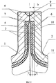
На фиг.1 - схема соединения деталей до сварки.Figure 1 - diagram of the connection of parts before welding.
На фиг.2 - вид А.Figure 2 - view A.
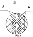
На фиг.3 - вид Б.Figure 3 is a view of B.
На фиг.4 - схема соединения деталей после сварки.Figure 4 - connection diagram of parts after welding.
Способ осуществляли следующим образом. Предварительно проводили подготовку кромок соединяемых деталей до нанесения покрытия. Перед сборкой на свариваемых кромках тонкостенных деталей 1 и 2 формировали отбортовку 3. На отбортовке 3 выполняли выступ 4 в направлении внутренней поверхности детали. Затем на внутренние поверхности деталей наносили покрытие. Внутренний слой 5 покрытия располагали на поверхности детали так, что часть поверхности отбортовки 3 под выступом 4 не содержала слоя 5 покрытия. Наружный слой 6 покрытия выполняли так, что он заполнял часть полости 7 между выступом 4 и торцом слоя 5. Толщина выступа - b, при этом b>t, где t - суммарная толщина покрытия, равная сумме толщин слоев: t1+t2, где: t1 - толщина внутреннего слоя и t2 - толщина наружного слоя покрытия. При b>t имеет место зазор между поверхностями соединяемых деталей с покрытием (см. фиг.2).The method was carried out as follows. Previously, the edges of the parts to be joined were prepared before coating. Before assembling, on the welded edges of thin-
При b=t зазор также имеет место, но он имеет прерывистую форму, т.к. касание осуществляется только по выступам поверхности покрытия (см. фиг.3) без плотного прилегания, предотвращая создание напряжений в хрупком слое 5. После сборки конструкции до соприкосновения поверхностей 8 выступов 4 осуществляли процесс сварки. В процессе сварки формирующийся сварной шов 9 передает тепловое воздействие на материал наружного слоя 6, заполняющего полость 7. При этом материал слоя 6, термопластичный при температуре сварки, затекает в зазор 10, обеспечивая отделение полости, образованной выступом и внутренним слоем покрытия, и защиту материала деталей от воздействия агрессивной среды 11, заполняющей корпус.At b = t, the gap also takes place, but it has an intermittent shape, because touch is carried out only on the protrusions of the surface of the coating (see Fig. 3) without a tight fit, preventing the creation of stresses in the
В процессе отработки конструкции в институте проводили герметизацию корпуса из стали с внутренним покрытием, первый слой которого выполняли из тугоплавкого оксида, а второй из композиционного материала на основе легкоплавкого стекла. Сварку осуществляли по отбортовке. Предварительно была проведена подготовка кромок соединяемых деталей. На отбортовке свариваемых деталей выполняли выступ на величину не менее толщины покрытия. Для получения выступа использовали несколько приемов:In the process of developing the structure at the Institute, the body was sealed with steel with an internal coating, the first layer of which was made of refractory oxide, and the second of a composite material based on low-melting glass. Welding was carried out by flanging. Previously, the preparation of the edges of the joined parts was carried out. On the flanging of the welded parts, a protrusion was performed for an amount not less than the coating thickness. To obtain the protrusion used several techniques:
- на торце детали, на котором формируется сварной шов, механическим путем создавали выступ на свариваемых деталях на величину не менее толщины покрытия,- at the end of the part on which the weld is formed, a protrusion on the parts to be welded was created mechanically by an amount not less than the coating thickness,
- торец детали, на котором формируется сварной шов оплавляли до получения валика, горизонтальное выступание которого в направлении сборки (внутренней поверхности) не менее толщины многослойного покрытия;- the end face of the part on which the weld is formed was melted until a roller was obtained, the horizontal protrusion of which in the assembly direction (inner surface) was not less than the thickness of the multilayer coating;
- к торцу детали, на котором формируется сварной шов, с помощью сварки присоединяли элемент, обеспечивающий создание выступа на свариваемых деталях на величину не менее толщины покрытия,- to the end of the part on which the weld is formed, by means of welding, an element is attached that ensures the creation of a protrusion on the parts to be welded by an amount not less than the coating thickness,
Затем наносили внутренний слой покрытия из тугоплавкого оксида на поверхность так, что часть поверхности детали под выступом оставалась не защищенной покрытием, а при формировании наружного слоя покрытия из легкоплавкого стекла его материалом заполняли часть полости под выступом. При необходимости наносили несколько слоев из материала наружного слоя, для более полного заполнения полости под выступом, но толщина покрытия при этом не превышала величину выступа. В качестве наружного слоя покрытия использовали композиционный материал на основе легкоплавкого стекла, который обладает термопластичными свойствами при нагреве до температуры сварки.Then, an inner coating layer of refractory oxide was applied to the surface so that part of the surface of the part under the protrusion remained unprotected by the coating, and when forming the outer coating layer of low-melting glass, part of the cavity under the protrusion was filled with its material. If necessary, several layers of the material of the outer layer were applied to more completely fill the cavity under the protrusion, but the thickness of the coating did not exceed the size of the protrusion. A composite material based on low-melting glass, which has thermoplastic properties when heated to a welding temperature, was used as the outer coating layer.
При сборке контакт по плоскости отбортовки, где детали имеют многослойное покрытие, осуществляли до касания поверхностей, исключая плотное прилегание, а при выполнении выступа размером более толщины покрытия при сборке в месте контакта отбортовок свариваемых деталей по покрытию появлялся зазор, величина которого была равна удвоенной разности между высотой выступа и толщиной покрытия. Сварку проводили по выступу, при этом материал наружного слоя, заполняющий полость под выступом, предотвращал контакт корня сварного шва и поверхностей полости, образованной выступом и внутренним слоем покрытия, где материал корпуса не имел покрытия, с внутренней агрессивной средой.When assembling, the contact along the flanging plane, where the parts have a multilayer coating, was made before touching the surfaces, excluding a tight fit, and when performing a protrusion larger than the thickness of the coating during assembly, a gap appeared at the contact point of the flanges of the welded parts along the coating, the value of which was equal to twice the difference between protrusion height and coating thickness. Welding was carried out along the protrusion, while the material of the outer layer filling the cavity under the protrusion prevented the contact of the root of the weld and the surfaces of the cavity formed by the protrusion and the inner coating layer, where the body material was not coated, with an internal aggressive environment.
Контроль качества защитного покрытия после испытания в контакте с металлическим расплавом оценивали методом микрорентгеноспектрального анализа. На внутренней стороне покрытия, по данным микрорентгеноспектрального анализа, присутствуют только элементы, входящие в состав стали, и элементы, присутствующие в защитных составах. Спектральные линии, принадлежащие компонентам внутренней агрессивной среды, отсутствуют. Металлографический анализ также показал отсутствие контакта внутренней агрессивной среды со сталью.The quality control of the protective coating after testing in contact with a metal melt was evaluated by X-ray spectral analysis. On the inner side of the coating, according to X-ray microanalysis, there are only elements that are part of the steel, and elements that are present in the protective compositions. The spectral lines belonging to the components of the internal aggressive environment are absent. Metallographic analysis also showed the absence of contact of the internal aggressive environment with steel.
Claims (1)
Priority Applications (1)
| Application Number | Priority Date | Filing Date | Title |
|---|---|---|---|
| RU2005125966/02A RU2294271C1 (en) | 2005-08-15 | 2005-08-15 | Materials and coating joining method |
Applications Claiming Priority (1)
| Application Number | Priority Date | Filing Date | Title |
|---|---|---|---|
| RU2005125966/02A RU2294271C1 (en) | 2005-08-15 | 2005-08-15 | Materials and coating joining method |
Publications (1)
| Publication Number | Publication Date |
|---|---|
| RU2294271C1 true RU2294271C1 (en) | 2007-02-27 |
Family
ID=37990620
Family Applications (1)
| Application Number | Title | Priority Date | Filing Date |
|---|---|---|---|
| RU2005125966/02A RU2294271C1 (en) | 2005-08-15 | 2005-08-15 | Materials and coating joining method |
Country Status (1)
| Country | Link |
|---|---|
| RU (1) | RU2294271C1 (en) |
Cited By (6)
| Publication number | Priority date | Publication date | Assignee | Title |
|---|---|---|---|---|
| RU2384674C1 (en) * | 2008-12-01 | 2010-03-20 | Общество с ограниченной ответственностью "АКВАБАРЬЕР" | Method for sealing of reinforced concrete pipes and sections of tunnel linings |
| RU2458277C1 (en) * | 2011-06-01 | 2012-08-10 | Открытое акционерное общество "Татнефть" им. В.Д. Шашина | Erection method of pipelines from metal-plastic pipes |
| RU2458768C1 (en) * | 2011-06-29 | 2012-08-20 | Федеральное Государственное унитарное предприятие "Государственное научно-производственное предприятие "Сплав" | Method of making thin-wall axially-symmetric welded structure with thick-wall mounted elements |
| RU2562200C1 (en) * | 2014-06-25 | 2015-09-10 | Российская Федерация, От Имени Которой Выступает Министерство Промышленности И Торговли Российской Федерации | Method of manufacturing of axisymmetric welded pressure shells |
| RU2677250C1 (en) * | 2018-03-01 | 2019-01-16 | Российская Федерация, от имени которой выступает Государственная корпорация по космической деятельности "РОСКОСМОС" | Method for sealing microcases |
| RU2697133C2 (en) * | 2017-10-18 | 2019-08-12 | Российская Федерация, от имени которой выступает Государственная корпорация по атомной энергии "Росатом" (Госкорпорация "Росатом") | Method of welding parts with coating using nonconsumable electrode |
Citations (5)
| Publication number | Priority date | Publication date | Assignee | Title |
|---|---|---|---|---|
| US4735835A (en) * | 1985-08-31 | 1988-04-05 | Toyo Seikan Kaisha, Ltd. | Seam covered welded can |
| SU1479249A1 (en) * | 1987-08-05 | 1989-05-15 | Казахский Государственный Научно-Исследовательский И Проектный Институт Нефтяной Промышленности | Method of welding pipes with internal enamel coating |
| SU1570870A1 (en) * | 1988-05-18 | 1990-06-15 | Институт Электросварки Им.Е.О.Патона | Method of joining cladded materials |
| SU1704993A1 (en) * | 1989-08-08 | 1992-01-15 | Татарский Государственный Научно-Исследовательский И Проектный Институт Нефтяной Промышленности | Method of preparing tubes with inner protective coating for welding |
| SU1764906A1 (en) * | 1989-09-07 | 1992-09-30 | Всесоюзный проектно-конструкторский технологический институт строительного, дорожного и коммунального машиностроения | Method of welding parts |
-
2005
- 2005-08-15 RU RU2005125966/02A patent/RU2294271C1/en not_active IP Right Cessation
Patent Citations (5)
| Publication number | Priority date | Publication date | Assignee | Title |
|---|---|---|---|---|
| US4735835A (en) * | 1985-08-31 | 1988-04-05 | Toyo Seikan Kaisha, Ltd. | Seam covered welded can |
| SU1479249A1 (en) * | 1987-08-05 | 1989-05-15 | Казахский Государственный Научно-Исследовательский И Проектный Институт Нефтяной Промышленности | Method of welding pipes with internal enamel coating |
| SU1570870A1 (en) * | 1988-05-18 | 1990-06-15 | Институт Электросварки Им.Е.О.Патона | Method of joining cladded materials |
| SU1704993A1 (en) * | 1989-08-08 | 1992-01-15 | Татарский Государственный Научно-Исследовательский И Проектный Институт Нефтяной Промышленности | Method of preparing tubes with inner protective coating for welding |
| SU1764906A1 (en) * | 1989-09-07 | 1992-09-30 | Всесоюзный проектно-конструкторский технологический институт строительного, дорожного и коммунального машиностроения | Method of welding parts |
Cited By (6)
| Publication number | Priority date | Publication date | Assignee | Title |
|---|---|---|---|---|
| RU2384674C1 (en) * | 2008-12-01 | 2010-03-20 | Общество с ограниченной ответственностью "АКВАБАРЬЕР" | Method for sealing of reinforced concrete pipes and sections of tunnel linings |
| RU2458277C1 (en) * | 2011-06-01 | 2012-08-10 | Открытое акционерное общество "Татнефть" им. В.Д. Шашина | Erection method of pipelines from metal-plastic pipes |
| RU2458768C1 (en) * | 2011-06-29 | 2012-08-20 | Федеральное Государственное унитарное предприятие "Государственное научно-производственное предприятие "Сплав" | Method of making thin-wall axially-symmetric welded structure with thick-wall mounted elements |
| RU2562200C1 (en) * | 2014-06-25 | 2015-09-10 | Российская Федерация, От Имени Которой Выступает Министерство Промышленности И Торговли Российской Федерации | Method of manufacturing of axisymmetric welded pressure shells |
| RU2697133C2 (en) * | 2017-10-18 | 2019-08-12 | Российская Федерация, от имени которой выступает Государственная корпорация по атомной энергии "Росатом" (Госкорпорация "Росатом") | Method of welding parts with coating using nonconsumable electrode |
| RU2677250C1 (en) * | 2018-03-01 | 2019-01-16 | Российская Федерация, от имени которой выступает Государственная корпорация по космической деятельности "РОСКОСМОС" | Method for sealing microcases |
Similar Documents
| Publication | Publication Date | Title |
|---|---|---|
| US3890483A (en) | Joints for protectively lined or coated metal pipe sections | |
| US2263021A (en) | Domestic hot water tank | |
| RU2027939C1 (en) | Pipe with internal plastic envelope | |
| US6131800A (en) | Method for coating and welding stator vanes of a gas turbine | |
| RU2294271C1 (en) | Materials and coating joining method | |
| RU2503873C1 (en) | Weld joint of pipes with internal corrosion protection coating | |
| JP2008531284A (en) | Clad metal bonding method and container manufactured thereby | |
| RU2635123C1 (en) | Dissimilar materials bonding with electronic beam technique | |
| CA2541410C (en) | Method of corrosion protection at a welded pipe joint and resulting joint | |
| US20200398362A1 (en) | Pipeline system of pipe sections with pre-assembled insulating weld backing rings and method of making same | |
| JP2025062001A (en) | Two-stage hermetic seal and its manufacturing method | |
| RU2207236C1 (en) | Titanium-steel reducer | |
| RU2600152C2 (en) | Method of joining coated parts | |
| RU126415U1 (en) | WELDED PIPES WITH INTERNAL ANTI-CORROSION COATING | |
| RU2232334C1 (en) | Method for joining tubes provided with inner envelope | |
| RU2236628C1 (en) | Method of pipe joining | |
| SU1764906A1 (en) | Method of welding parts | |
| CN101119673A (en) | insulated container | |
| JPH04276222A (en) | Synthetic resin vacuum insulation vessel and manufacture thereof | |
| RU2005616C1 (en) | Method of connection of pipes with inner protective coating | |
| RU2272215C1 (en) | Method of joining pipes with inner anticorrosive coating | |
| JPS6124257B2 (en) | ||
| JP3726039B2 (en) | Manufacturing method of inner surface coated container | |
| RU2697133C2 (en) | Method of welding parts with coating using nonconsumable electrode | |
| JPH0131078B2 (en) |
Legal Events
| Date | Code | Title | Description |
|---|---|---|---|
| MM4A | The patent is invalid due to non-payment of fees |
Effective date: 20090816 |