US6131800A - Method for coating and welding stator vanes of a gas turbine - Google Patents
Method for coating and welding stator vanes of a gas turbine Download PDFInfo
- Publication number
- US6131800A US6131800A US09/493,135 US49313500A US6131800A US 6131800 A US6131800 A US 6131800A US 49313500 A US49313500 A US 49313500A US 6131800 A US6131800 A US 6131800A
- Authority
- US
- United States
- Prior art keywords
- welding
- platform
- filler material
- stator vane
- vane
- Prior art date
- Legal status (The legal status is an assumption and is not a legal conclusion. Google has not performed a legal analysis and makes no representation as to the accuracy of the status listed.)
- Expired - Lifetime
Links
Images


Classifications
-
- B—PERFORMING OPERATIONS; TRANSPORTING
- B23—MACHINE TOOLS; METAL-WORKING NOT OTHERWISE PROVIDED FOR
- B23K—SOLDERING OR UNSOLDERING; WELDING; CLADDING OR PLATING BY SOLDERING OR WELDING; CUTTING BY APPLYING HEAT LOCALLY, e.g. FLAME CUTTING; WORKING BY LASER BEAM
- B23K33/00—Specially-profiled edge portions of workpieces for making soldering or welding connections; Filling the seams formed thereby
- B23K33/004—Filling of continuous seams
-
- Y—GENERAL TAGGING OF NEW TECHNOLOGICAL DEVELOPMENTS; GENERAL TAGGING OF CROSS-SECTIONAL TECHNOLOGIES SPANNING OVER SEVERAL SECTIONS OF THE IPC; TECHNICAL SUBJECTS COVERED BY FORMER USPC CROSS-REFERENCE ART COLLECTIONS [XRACs] AND DIGESTS
- Y10—TECHNICAL SUBJECTS COVERED BY FORMER USPC
- Y10T—TECHNICAL SUBJECTS COVERED BY FORMER US CLASSIFICATION
- Y10T29/00—Metal working
- Y10T29/49—Method of mechanical manufacture
- Y10T29/49316—Impeller making
- Y10T29/4932—Turbomachine making
- Y10T29/49321—Assembling individual fluid flow interacting members, e.g., blades, vanes, buckets, on rotary support member
Definitions
- the invention relates to a method for coating and welding stator vanes of a gas turbine.
- vanes of a gas turbine it is known from the state of the art to form the vanes of a gas turbine as singlets to be connected to the stator of a gas turbine. Because the vanes are exposed to the hot gases of the gas turbine, for reasons of improving overall performance and efficiency, the vanes have to be coated with coating materials different than the base material from which the vanes are manufactured. It is generally known from the state of the art to use MCrAlY as a bond layer coating to provide a resistance to oxidation and corrosion to the base material. On top of this bond coating, there is applied a second or top coating of yttrium stabilized zirconia having thermal insulating and anti-corrosion properties.
- each vane has the known advantage that it is possible to coat each single vane in the same quality and at a uniform thickness at all the surfaces exposed to the hot gases in comparison to a multi-vane-segment, where due to the geometry only portions can fully be coated to the desired coating thickness and often portions of the vane are only coated with one of both or even remain uncoated. This would immediately lead to undesirable temperature variations along the surface of the vane. For that reason from patent U.S. Pat. No.
- a method for providing a nozzle segment as a singlet, applying to each singlet a bond and a top layer coating, and then securing two nozzle segments to one another by welding margins of adjacent walls to one another. This is done by butting the margins of the inner walls of adjoining segments against one another whereby the welding includes fusing the material of the butting margins in a direction along that margins terminating shortly before the coated wall surfaces such that said wall surfaces and the base and top coatings there along are not penetrated by fused material.
- the distance between the coated surfaces and the fused material might be less than 8 mils.
- the microcracks may range from 500 microns to more than 1 millimetre. Such microcracks constitute a zone of such weakness that they can not be allowed in the component, even in moderately loaded areas. Cracks may start growing immediately at this point of weakness.
- the material of choice for a particular vane application is seldom based on its weldability but rather the castability, high temperature strength and environmental resistance. Hence, it will often be the case that the material from which vanes are manufactured is not easily or acceptably weldable.
- the step of welding is desirable because it clearly reduces the leakage of the cooling air through the margins of two adjacent vanes and so the overall efficiency of the gas turbine is increased.
- a method was found of applying a surface coating to a stator vane of a gas turbine, the stator vane comprising a platform with an outer surface connected to the stator of the gas turbine and an airfoil connected to the platform, the method comprising the steps of each stator vane is provided as a singlet, a base layer coating affording resistance to oxidation is applied to surfaces of said stator vane and said outer surface of the platform to be exposed to hot gases of the gas turbine, and a top layer coating affording thermal resistance is applied to all coated surfaces of said stator vane and the outer surface of the platform, and welding the stator vanes together, wherein a welding filler material is placed between said walls of two adjacent platforms of said stator vane, welding said singlets to one another at the margins of walls of said platform to said welding filler material.
- the welding filler material between two platforms of stator vanes reduces the formation of micro-cracks during solidification after welding. This method will increase the resistance against the thermal stresses and the forming of microcracks with the result of a significant lifetime increase.
- a welding filler material which is different from the parent material is appropriate while it has no harmful effect on the physical properties of the adjoining vanes in the region of the welding joint.
- the problem of microcracks occurs especially where the parents material of a stator vane is a nickel based superalloy such as MAR-M247.
- the welding filler material might be IN625, which has adequate properties like high temperature strength.
- the coating material of the stator vane and the side of the platform which is exposed to the hot gases of the gas turbine is with advantage MCrAlY as a base layer coating to provide a resistance to oxidation and corrosion and Y stabilised Zr-Oxide having thermal insulating and anti-corrosion properties.
- MCrAlY as a base layer coating to provide a resistance to oxidation and corrosion
- Y stabilised Zr-Oxide having thermal insulating and anti-corrosion properties.
- any method of welding might be useful, especially electrobeam-, laser- or TIG-welding.
- electrobeam-, laser- or TIG-welding To accommodate the welding filler material between the two stator vanes without generating a gap at the surfaces of the coated platform which would happen due to the additional material it might be an advantage to employ two corresponding castings which leaves a space or step where said welding filler material can be accommodated.
- the first reason is to avoid molten welding material coming from the welding joint from harming the coating.
- the second reason is to avoid a leak of cooling air in case the welding joint is partially cracked during service.
- any single vane can be coated with the protective base and top layer to a full extent and then welded together.
- the leakage of the cooling air which escapes between the two vanes can be significantly reduced due to the sealing effect of the weld.
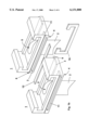
- FIG. 1a is a perspective view of two gas turbine vanes provided as singlets
- FIG. 1b is a perspective view of another embodiment of two gas turbine vanes provided as singlets
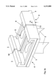
- FIG. 2a is a perspective view of a third embodiment showing the gas turbine vane doublet welded to one another from two singlets,
- FIG. 2b is a perspective view of another embodiment of gas turbine vane doublet welded to one another from two singlets
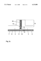
- FIG. 3a is a cross section through a welding joint at the wall of a platform of two adjoining gas turbine vane singlets with a welding filler material in between,
- FIG. 3b is a section through an other form of a welding joint at the wall of a platform of two adjoining gas turbine vane singlets with a welding filler material in between and
- FIG. 3c a cross section through a welding joint at the wall of a platform of two adjoining gas turbine vane singlet with a welding filler material in between and a seal slot between welding joint and coating material, and an additional sealing plate within the seal slot.
- each vane 1 comprising a platform 3 and an airfoil 2 connected to the platform 3.
- a cooling system 5 which is not illustrated in detail in FIG. 1a but which is essentially known from the prior art and which receives a cooling medium to cool the airfoil 2 as well as the platform 3.
- the airfoil 2 and the outer surface 4 of the platform 3 of each singlet will be coated separately with two layers of coating, a base layer coating 7 providing resistance to oxidation and a top layer coating 8 having thermal insulating and anti-corrosion properties. Both coatings are not shown in FIG. 1a but will be illustrated in FIG. 3a,b,c.
- FIG. 1a there is provided a step 6 at adjoining walls of the vanes 1 for the welding filler material 10 to be accommodated.
- the step 6 is advantageous but not necessary for the method according to the invention.
- FIG. 1b shows in principal the same embodiment of the invention with two vanes 1 comprising a plafform 3, an airfoil 2 and a welding filler material 10 to be placed in between two adjoining walls of the vane 1 with a step 6 within these walls.
- a sealing slot 11 in the platform 3 between the step 6 and the outer surface 4 at both adjoining sides of the vane 1. Before both vanes are butted together, the sealing slot 11 is filled with a sealing plate 12.
- FIG. 2a illustrates the two vanes 1 of a gas turbine welded together as a doublet in accordance with FIG. 1a.
- the welding zone 9 is made between the wall of a vane 1 and the welding filler material 10.
- FIG. 2b illustrates the two vanes 1 of a gas turbine welded together as a doublet in accordance with FIG. 1b.
- the welding zone 9 is made between the wall of a vane 1 and the welding filler material 10 but in difference with the FIG. 2a the sealing plate 12 incorporated in the sealing slot 11 (shown as dotted lines) prevents the leaking of molten welding material to the outer surface 4 on one side and on the other side reduced the leakage of the cooling medium from the cooling system 5 during services of the multi-segment vane.
- FIG. 3a A cross section of the adjacent walls of the platform 3 of two stator vanes 1 is illustrated by FIG. 3a, the platform 3 comprising a outer surface 4 exposed to the hot gases. Both outer surfaces 4 and the airfoil 2, the airfoil 2 is not shown in FIG. 3a, are coated with a base layer coating 7 provided resistance to oxidation and a top layer 8 coating having thermal insulating and anti-corrosion properties at the outer surface 4.
- the coating material of the stator vane 1 is with advantage MCrAlY as a base layer coating 7 and Y stabilised Zr-Oxide as a top layer coating 8.
- the welding filler material 10 is placed between the two platforms 3 of stator vanes 1. In principle the welding region is marked with 9.
- the welding filler material 10 reduces the production of micro-cracks during solidification after welding. This method will increase the resistance against the thermal stress and that forming of microcracks with the result of a significant lifetime increase.
- a welding filler material 10 which is different from the parent material is appropriate while it has no harmful effect on the physical properties of the adjoining vanes 1 in the region of the welding joint 9.
- the welding filler material 10 should have at least a thickness of 1/10 millimetre.
- the problem of microcracks occurs especially where the parent material of a stator vane is a nickel base superalloy such as MAR-M247.
- the welding filler material 10 might be IN625. Table 1 shows the contents of these materials.
- FIG. 3a Due to the welding filler material 10 in FIG. 3a shows a gap between the two adjacent outer surfaces 4 of the stator vanes 1.
- the non coated gap can be harmed in respect to the hot environment, but the resistance properties of the welding filler material 10 should be sufficient to avoid oxidation.
- FIG. 3b A cross section of the adjacent walls of the platform 3 of two stator vanes 1 is illustrated by FIG. 3b, with is an embodiment according to FIG. 2a.
- the method according to the invention includes butting the margins of the wall of adjoining vane 1 platforms 3 against one another and the step of welding includes fusing the material of the butting wall margins in radial inward direction along said margins terminating shortly before said wall surfaces 4 such that said wall surfaces of the platform 3 and the base and the top layer coating 7,8 there along are not penetrated by fused material.
- the distance h from the apex 13 of the welding joint 9 to the outer surface 4 is indicated in FIG. 3b by a strait line.
- the depth h in a radial direction is 8 millimetres or less and greater than 1 millimetre to prevent that disruption as well as to prevent propagation of an opening or crack during the life cycle of the gas turbine. That is, if the depth h is greater than 8 millimetres, there would be a potential for a crack to develop between the segments.
- a step 6 in which the welding filler material 10 can be placed. The step 6 is useful as well for fixturing the segments relative to one another during welding.
- any method of welding might be useful, especially electrobeam-, laser- or TIG-welding.
- FIG. 3c A cross section of the adjacent walls of the platform 3 of two stator vanes 1 is illustrated by FIG. 3c, which is an embodiment according to FIG. 2b. It might be advantageous to have on the wall of one or both parts a sealing slot 11 which may be cast or machined in between the apex 13 and the outer surface 3 at both adjoining walls preventing leaking molten welding material from coming into contact with the coating material 7,8. As seen in FIG. 3c there is placed a sealing plate 12 in this sealing slot 11 for different reasons.
- the first reason for placing a sealing plate 12 in the sealing 11 is to assure in a better way that fused welding material does not harm the base layer coating 7 which comes from the welding joint during welding and the sealing plate 12 stops as well the welding energy from penetrating to the coatings more effectively than the base material of the vanes.
- the second reason is to avoid a leak of cooling air in case the welding joint is not sealed in a proper manner.
- the sealing material has to have high thermal resistance. For this purpose a material like Hastelloy X, Haynes 214 or PM 2000 has good properties.
- any single vane can be coated with the protective base and top layer and welded thereafter such that the leakage of the cooling air which escapes due to the weld joint between two adjacent vanes can be significantly reduced.
Landscapes
- Engineering & Computer Science (AREA)
- Mechanical Engineering (AREA)
- Turbine Rotor Nozzle Sealing (AREA)
Abstract
Description
              TABLE 1
______________________________________
       Cr       Co     Mo    W    Ta    Al  Ti
______________________________________
MAR-247
        8.4     10.0   0.7   10.0 3.0   5.5 1.0
IN 625 21.5     --     8.5   --   --    0.5 0.2
______________________________________
        Hf    C        B    Zr      Ni   Fe    Nb
______________________________________
MAR-247 1.3   0.15     0.015
                            0.0045  bal. --    --
IN 625  --    0.06     --   --      bal. 2.5   4.0
______________________________________
              TABLE 2
______________________________________
        Cr     Co     Mo  W     Al   C    B    Zr
______________________________________
Hastelloy X
        21.0   1.5    9.0 0.6   --   0.2  --   --
Haynes 214
        16.0   --     --  --    4.5  0.05 0.01 0.1
PM2000  19.0   --     --  --    5.5  --   --   --
______________________________________
        Fe     Ni     Fe    Y    Si   Mn   Y.sub.2 O.sub.3
                                                Ti
______________________________________
Hastelloy X
        18.5   bal.   18.5  --   --   --   --   --
Haynes 214
         3.0   bal.    3.0  0.01 0.2  0.5  --   --
PM2000  --     --     bal.  --   --   --   0.5  0.5
______________________________________
Claims (16)
Applications Claiming Priority (2)
| Application Number | Priority Date | Filing Date | Title |
|---|---|---|---|
| EP99811000 | 1999-11-03 | ||
| EP99811000A EP1097779B1 (en) | 1999-11-03 | 1999-11-03 | Method for coating and welding stator of a gas turbine |
Publications (1)
| Publication Number | Publication Date |
|---|---|
| US6131800A true US6131800A (en) | 2000-10-17 |
Family
ID=8243123
Family Applications (1)
| Application Number | Title | Priority Date | Filing Date |
|---|---|---|---|
| US09/493,135 Expired - Lifetime US6131800A (en) | 1999-11-03 | 2000-01-28 | Method for coating and welding stator vanes of a gas turbine |
Country Status (3)
| Country | Link |
|---|---|
| US (1) | US6131800A (en) |
| EP (1) | EP1097779B1 (en) |
| DE (1) | DE69927594T2 (en) |
Cited By (20)
| Publication number | Priority date | Publication date | Assignee | Title |
|---|---|---|---|---|
| US6553665B2 (en) * | 2000-03-08 | 2003-04-29 | General Electric Company | Stator vane assembly for a turbine and method for forming the assembly |
| US20040151580A1 (en) * | 2003-02-03 | 2004-08-05 | Helder Earl Claude | Methods and apparatus for coupling a component to a turbine engine blade |
| US20040149696A1 (en) * | 2003-02-03 | 2004-08-05 | Helder Earl Claude | Methods and apparatus for fabricating a turbine engine blade |
| US20040238508A1 (en) * | 2003-05-27 | 2004-12-02 | Rabinovich Joshua E. | Low heat input laser component repair or joining with feedstock having conforming surfaces with a substrate |
| US20050067466A1 (en) * | 2001-11-19 | 2005-03-31 | Andreas Boegli | Crack repair method |
| EP1803896A2 (en) * | 2005-12-20 | 2007-07-04 | General Electric Company | Gas turbine nozzle segment and process therefor |
| US20070189894A1 (en) * | 2006-02-15 | 2007-08-16 | Thamboo Samuel V | Methods and apparatus for turbine engine rotors |
| US20080072569A1 (en) * | 2006-09-27 | 2008-03-27 | Thomas Ory Moniz | Guide vane and method of fabricating the same |
| US20090274562A1 (en) * | 2008-05-02 | 2009-11-05 | United Technologies Corporation | Coated turbine-stage nozzle segments |
| US20100032414A1 (en) * | 2007-03-23 | 2010-02-11 | Nikolai Arjakine | Inert gas mixture and method for welding |
| US20100209235A1 (en) * | 2009-02-18 | 2010-08-19 | Dong-Jin Shim | Method and apparatus for a structural outlet guide vane |
| US20150352649A1 (en) * | 2013-03-15 | 2015-12-10 | United Technologies Corporation | Multi-Airfoil Split and Rejoin Method to Produce Enhanced Durability Coating |
| EP3006712A4 (en) * | 2013-06-06 | 2017-01-25 | IHI Corporation | Fan blade and fan |
| US10584602B2 (en) | 2013-03-15 | 2020-03-10 | United Technologies Corporation | Multi-airfoil split and rejoin method |
| CN114411087A (en) * | 2021-12-29 | 2022-04-29 | 西安鑫垚陶瓷复合材料有限公司 | Turbine guide blade coating preparation tool and coating preparation method |
| CN115401421A (en) * | 2022-09-22 | 2022-11-29 | 中国航发北京航空材料研究院 | Preparation method of multi-connected turbine guide vane |
| US11512596B2 (en) | 2021-03-25 | 2022-11-29 | Raytheon Technologies Corporation | Vane arc segment with flange having step |
| US20230147399A1 (en) * | 2021-06-18 | 2023-05-11 | Raytheon Technologies Corporation | Joining individual turbine vanes with field assisted sintering technology (fast) |
| US12037912B2 (en) | 2021-06-18 | 2024-07-16 | Rtx Corporation | Advanced passive clearance control (APCC) control ring produced by field assisted sintering technology (FAST) |
| US12055056B2 (en) | 2021-06-18 | 2024-08-06 | Rtx Corporation | Hybrid superalloy article and method of manufacture thereof |
Citations (5)
| Publication number | Priority date | Publication date | Assignee | Title |
|---|---|---|---|---|
| US4726104A (en) * | 1986-11-20 | 1988-02-23 | United Technologies Corporation | Methods for weld repairing hollow, air cooled turbine blades and vanes |
| US4874290A (en) * | 1988-08-26 | 1989-10-17 | Solar Turbines Incorporated | Turbine blade top clearance control system |
| US5156321A (en) * | 1990-08-28 | 1992-10-20 | Liburdi Engineering Limited | Powder metallurgy repair technique |
| US5395584A (en) * | 1992-06-17 | 1995-03-07 | Avco Corporation | Nickel-base superalloy compositions |
| US5636439A (en) * | 1995-05-22 | 1997-06-10 | General Electric Co. | Methods for coating and securing multi-vane nozzle segments |
Family Cites Families (3)
| Publication number | Priority date | Publication date | Assignee | Title |
|---|---|---|---|---|
| BE534709A (en) * | ||||
| GB1228159A (en) * | 1967-08-21 | 1971-04-15 | ||
| CH594471A5 (en) * | 1976-07-02 | 1978-01-13 | Bbc Brown Boveri & Cie |
-
1999
- 1999-11-03 EP EP99811000A patent/EP1097779B1/en not_active Expired - Lifetime
- 1999-11-03 DE DE69927594T patent/DE69927594T2/en not_active Expired - Lifetime
-
2000
- 2000-01-28 US US09/493,135 patent/US6131800A/en not_active Expired - Lifetime
Patent Citations (5)
| Publication number | Priority date | Publication date | Assignee | Title |
|---|---|---|---|---|
| US4726104A (en) * | 1986-11-20 | 1988-02-23 | United Technologies Corporation | Methods for weld repairing hollow, air cooled turbine blades and vanes |
| US4874290A (en) * | 1988-08-26 | 1989-10-17 | Solar Turbines Incorporated | Turbine blade top clearance control system |
| US5156321A (en) * | 1990-08-28 | 1992-10-20 | Liburdi Engineering Limited | Powder metallurgy repair technique |
| US5395584A (en) * | 1992-06-17 | 1995-03-07 | Avco Corporation | Nickel-base superalloy compositions |
| US5636439A (en) * | 1995-05-22 | 1997-06-10 | General Electric Co. | Methods for coating and securing multi-vane nozzle segments |
Cited By (30)
| Publication number | Priority date | Publication date | Assignee | Title |
|---|---|---|---|---|
| US6553665B2 (en) * | 2000-03-08 | 2003-04-29 | General Electric Company | Stator vane assembly for a turbine and method for forming the assembly |
| US20050067466A1 (en) * | 2001-11-19 | 2005-03-31 | Andreas Boegli | Crack repair method |
| US6964557B2 (en) * | 2003-02-03 | 2005-11-15 | General Electric Company | Methods and apparatus for coupling a component to a turbine engine blade |
| US20040151580A1 (en) * | 2003-02-03 | 2004-08-05 | Helder Earl Claude | Methods and apparatus for coupling a component to a turbine engine blade |
| US20040149696A1 (en) * | 2003-02-03 | 2004-08-05 | Helder Earl Claude | Methods and apparatus for fabricating a turbine engine blade |
| US6933459B2 (en) * | 2003-02-03 | 2005-08-23 | General Electric Company | Methods and apparatus for fabricating a turbine engine blade |
| US20040238508A1 (en) * | 2003-05-27 | 2004-12-02 | Rabinovich Joshua E. | Low heat input laser component repair or joining with feedstock having conforming surfaces with a substrate |
| US7600666B2 (en) * | 2003-05-27 | 2009-10-13 | Rabinovich Joshua E | Repair with feedstock having conforming surfaces with a substrate |
| EP1803896A2 (en) * | 2005-12-20 | 2007-07-04 | General Electric Company | Gas turbine nozzle segment and process therefor |
| EP1803896A3 (en) * | 2005-12-20 | 2008-05-07 | General Electric Company | Gas turbine nozzle segment and process therefor |
| US20070189894A1 (en) * | 2006-02-15 | 2007-08-16 | Thamboo Samuel V | Methods and apparatus for turbine engine rotors |
| JP2007218260A (en) * | 2006-02-15 | 2007-08-30 | General Electric Co <Ge> | Rotor for turbine engine and device for welding rotor |
| US20080072569A1 (en) * | 2006-09-27 | 2008-03-27 | Thomas Ory Moniz | Guide vane and method of fabricating the same |
| US20100032414A1 (en) * | 2007-03-23 | 2010-02-11 | Nikolai Arjakine | Inert gas mixture and method for welding |
| US20090274562A1 (en) * | 2008-05-02 | 2009-11-05 | United Technologies Corporation | Coated turbine-stage nozzle segments |
| US20100209235A1 (en) * | 2009-02-18 | 2010-08-19 | Dong-Jin Shim | Method and apparatus for a structural outlet guide vane |
| US8177513B2 (en) | 2009-02-18 | 2012-05-15 | General Electric Company | Method and apparatus for a structural outlet guide vane |
| US20150352649A1 (en) * | 2013-03-15 | 2015-12-10 | United Technologies Corporation | Multi-Airfoil Split and Rejoin Method to Produce Enhanced Durability Coating |
| US10239142B2 (en) * | 2013-03-15 | 2019-03-26 | United Technologies Corporation | Multi-airfoil split and rejoin method to produce enhanced durability coating |
| US10584602B2 (en) | 2013-03-15 | 2020-03-10 | United Technologies Corporation | Multi-airfoil split and rejoin method |
| EP3006712A4 (en) * | 2013-06-06 | 2017-01-25 | IHI Corporation | Fan blade and fan |
| US9976430B2 (en) | 2013-06-06 | 2018-05-22 | Ihi Corporation | Blade in fan, and fan |
| US11512596B2 (en) | 2021-03-25 | 2022-11-29 | Raytheon Technologies Corporation | Vane arc segment with flange having step |
| US12037912B2 (en) | 2021-06-18 | 2024-07-16 | Rtx Corporation | Advanced passive clearance control (APCC) control ring produced by field assisted sintering technology (FAST) |
| US12055056B2 (en) | 2021-06-18 | 2024-08-06 | Rtx Corporation | Hybrid superalloy article and method of manufacture thereof |
| US20230147399A1 (en) * | 2021-06-18 | 2023-05-11 | Raytheon Technologies Corporation | Joining individual turbine vanes with field assisted sintering technology (fast) |
| CN114411087A (en) * | 2021-12-29 | 2022-04-29 | 西安鑫垚陶瓷复合材料有限公司 | Turbine guide blade coating preparation tool and coating preparation method |
| CN114411087B (en) * | 2021-12-29 | 2023-09-29 | 西安鑫垚陶瓷复合材料有限公司 | Turbine guide vane coating preparation tool and coating preparation method |
| CN115401421B (en) * | 2022-09-22 | 2024-03-26 | 中国航发北京航空材料研究院 | Preparation method of multi-connected turbine guide vane |
| CN115401421A (en) * | 2022-09-22 | 2022-11-29 | 中国航发北京航空材料研究院 | Preparation method of multi-connected turbine guide vane |
Also Published As
| Publication number | Publication date |
|---|---|
| EP1097779A1 (en) | 2001-05-09 |
| EP1097779B1 (en) | 2005-10-05 |
| DE69927594D1 (en) | 2005-11-10 |
| DE69927594T2 (en) | 2006-07-20 |
Similar Documents
| Publication | Publication Date | Title |
|---|---|---|
| US6131800A (en) | Method for coating and welding stator vanes of a gas turbine | |
| US5968672A (en) | Weldment produced by beam welding | |
| JPS6039475B2 (en) | flat or curved workpieces prepared for electron beam welding | |
| JP3409674B2 (en) | Annular joining method, sealed container and viscous damper obtained thereby | |
| CN105408055A (en) | Building and repair of hollow components | |
| US6685431B2 (en) | Method for repairing a turbine vane | |
| US20110062220A1 (en) | Superalloy composition and method of forming a turbine engine component | |
| EP0744529B1 (en) | Methods for coating and securing multi-vane nozzle segments | |
| US6129257A (en) | High temperature brazing fixture | |
| JP2020147846A (en) | Manufactured article and method | |
| FI80129C (en) | FOERFARANDE FOER FRAMSTAELLNING AV EN TERMISKT OCH MEKANISKT HOEGT BELASTBAR OCH MOT KORROSION SKYDDAD GASVAEXELVENTIL FOER EN MED TUNG BRAENNOLJA DRIVEN FOERBRAENNINGSMOTOR. | |
| EP0893653A2 (en) | Protective coatings for turbine combustion components | |
| US20080118768A1 (en) | Laser fillet welding | |
| KR101380659B1 (en) | Method for welding inner plate and cover plate and rudder manufacturing method having the same | |
| CN107795338B (en) | Turbine engine blade component | |
| JPH11114672A (en) | Joining method for titanium clad steel to steel structure | |
| CN110369845A (en) | Resistance spot welding has the job stacking part of surface covering steel workpiece | |
| CN110711938A (en) | Laser welding method for silencer and cylinder cover | |
| JP4337721B2 (en) | High energy density beam welding product, high energy density beam welding method, and welding auxiliary device used therefor | |
| JP2018091333A (en) | Methods for forming vertically cracked thermal barrier coatings and articles including vertically cracked thermal barrier coatings | |
| JPH0569240A (en) | Method of forming hollow wear-resisting ring for diesel engine piston | |
| JP3046026B1 (en) | Steam turbine partition and method for producing the same | |
| JP3487021B2 (en) | How to locally strengthen aluminum | |
| EP1925391A1 (en) | Laser fillet welding | |
| CN117532131B (en) | Rocket engine combustion chamber and manufacturing method thereof |
Legal Events
| Date | Code | Title | Description |
|---|---|---|---|
| AS | Assignment |
Owner name: ABB ALSTOM POWER (SCHWEIZ) AG, SWITZERLAND Free format text: ASSIGNMENT OF ASSIGNORS INTEREST;ASSIGNORS:FERNIHOUGH, JOHN;BEECK, ALEXANDER;ANDERSON, GORDON DAVID;REEL/FRAME:010540/0064 Effective date: 20000120 |
|
| STCF | Information on status: patent grant |
Free format text: PATENTED CASE |
|
| FEPP | Fee payment procedure |
Free format text: PAYOR NUMBER ASSIGNED (ORIGINAL EVENT CODE: ASPN); ENTITY STATUS OF PATENT OWNER: LARGE ENTITY |
|
| AS | Assignment |
Owner name: ALSTOM (SWITZERLAND) LTD, SWITZERLAND Free format text: CHANGE OF NAME;ASSIGNOR:ABB ALSTOM POWER (SCHWEIZ) AG;REEL/FRAME:013067/0106 Effective date: 20001222 |
|
| FPAY | Fee payment |
Year of fee payment: 4 |
|
| FPAY | Fee payment |
Year of fee payment: 8 |
|
| FPAY | Fee payment |
Year of fee payment: 12 |
|
| AS | Assignment |
Owner name: ALSTOM TECHNOLOGY LTD, SWITZERLAND Free format text: ASSIGNMENT OF ASSIGNORS INTEREST;ASSIGNOR:ALSTOM (SWITZERLAND) LTD;REEL/FRAME:028929/0381 Effective date: 20120525 |
|
| AS | Assignment |
Owner name: GENERAL ELECTRIC TECHNOLOGY GMBH, SWITZERLAND Free format text: CHANGE OF NAME;ASSIGNOR:ALSTOM TECHNOLOGY LTD;REEL/FRAME:038216/0193 Effective date: 20151102 |