RU2291993C2 - Ball transmitting unit of variator - Google Patents
Ball transmitting unit of variator Download PDFInfo
- Publication number
- RU2291993C2 RU2291993C2 RU2004129188/11A RU2004129188A RU2291993C2 RU 2291993 C2 RU2291993 C2 RU 2291993C2 RU 2004129188/11 A RU2004129188/11 A RU 2004129188/11A RU 2004129188 A RU2004129188 A RU 2004129188A RU 2291993 C2 RU2291993 C2 RU 2291993C2
- Authority
- RU
- Russia
- Prior art keywords
- disk
- shaft
- eccentric
- sleeve
- module
- Prior art date
Links
Images


Classifications
-
- F—MECHANICAL ENGINEERING; LIGHTING; HEATING; WEAPONS; BLASTING
- F16—ENGINEERING ELEMENTS AND UNITS; GENERAL MEASURES FOR PRODUCING AND MAINTAINING EFFECTIVE FUNCTIONING OF MACHINES OR INSTALLATIONS; THERMAL INSULATION IN GENERAL
- F16H—GEARING
- F16H57/00—General details of gearing
- F16H57/02—Gearboxes; Mounting gearing therein
- F16H57/033—Series gearboxes, e.g. gearboxes based on the same design being available in different sizes or gearboxes using a combination of several standardised units
-
- F—MECHANICAL ENGINEERING; LIGHTING; HEATING; WEAPONS; BLASTING
- F16—ENGINEERING ELEMENTS AND UNITS; GENERAL MEASURES FOR PRODUCING AND MAINTAINING EFFECTIVE FUNCTIONING OF MACHINES OR INSTALLATIONS; THERMAL INSULATION IN GENERAL
- F16H—GEARING
- F16H25/00—Gearings comprising primarily only cams, cam-followers and screw-and-nut mechanisms
- F16H25/04—Gearings comprising primarily only cams, cam-followers and screw-and-nut mechanisms for conveying rotary motion
- F16H25/06—Gearings comprising primarily only cams, cam-followers and screw-and-nut mechanisms for conveying rotary motion with intermediate members guided along tracks on both rotary members
- F16H2025/063—Gearings comprising primarily only cams, cam-followers and screw-and-nut mechanisms for conveying rotary motion with intermediate members guided along tracks on both rotary members the intermediate members being balls engaging on opposite cam discs
-
- F—MECHANICAL ENGINEERING; LIGHTING; HEATING; WEAPONS; BLASTING
- F16—ENGINEERING ELEMENTS AND UNITS; GENERAL MEASURES FOR PRODUCING AND MAINTAINING EFFECTIVE FUNCTIONING OF MACHINES OR INSTALLATIONS; THERMAL INSULATION IN GENERAL
- F16H—GEARING
- F16H57/00—General details of gearing
- F16H57/02—Gearboxes; Mounting gearing therein
- F16H57/033—Series gearboxes, e.g. gearboxes based on the same design being available in different sizes or gearboxes using a combination of several standardised units
- F16H2057/0335—Series transmissions of modular design, e.g. providing for different transmission ratios or power ranges
Abstract
Description
Изобретение относится к области общего машиностроения, а именно к механизмам для преобразования скорости вращения без использования зубчатых колес, а более конкретно к передачам момента вращения посредством цепочки шариков. Оно может быть использовано в приводах машин и механизмов самого широкого назначения. Особенно перспективно его использование в качестве модуля для конструирования ступенчатых коробок переключения скоростей по различным схемам соединения.The invention relates to the field of general engineering, and in particular to mechanisms for converting rotation speed without the use of gears, and more particularly to transmitting torque through a chain of balls. It can be used in drives of machines and mechanisms of the broadest purpose. Especially promising is its use as a module for the construction of speed gearboxes according to various connection schemes.
Известен эпициклический редуктор (US 4643047), содержащий диск, закрепленный на корпусе (статор), и выходной диск, между которыми расположен промежуточный диск. Промежуточный диск посажен с возможностью вращения на эксцентрике входного вала. На обращенных друг к другу поверхностях статора, и выходного диска, а также на обеих поверхностях промежуточного диска выполнены периодические эпи- и гипотрохоидальные дорожки. В сопрягающихся дорожках статора и промежуточного диска расположена цепочка шариков, каждый из которых контактирует одновременно с обеими дорожками с передачей момента вращения. Точно так же в аналогичных дорожках промежуточного и выходного дисков расположена вторая цепочка шариков.Known epicyclic reducer (US 4643047), containing a disk mounted on the housing (stator), and an output disk, between which is located an intermediate disk. The intermediate disk is mounted rotatably on the cam of the input shaft. On the surfaces of the stator and the output disk facing each other, as well as on both surfaces of the intermediate disk, periodic epi- and hyprochoidal tracks are made. In the mating tracks of the stator and the intermediate disk there is a chain of balls, each of which contacts simultaneously with both tracks with the transmission of torque. Similarly, in the similar tracks of the intermediate and output disks, a second chain of balls is located.
По аналогичному принципу построен дифференциальный преобразователь скорости, изображенный на фиг.8 в патенте US 4829851. Передающий узел данного преобразователя авторы назвали "беззубым", так как он построен без зубчатых колес. Передающий узел содержит три установленных последовательно диска. Крайние диски имеют на обращенных друг к другу поверхностях замкнутые периодические синусоидальные дорожки качения. Средний диск имеет на обеих своих поверхностях замкнутые периодические дорожки, которые совместно с дорожками крайних дисков образуют две пары сопрягающихся дорожек, зацепляющихся посредством двух цепочек шариков. Каждый шарик в цепочке контактирует с обеими сопрягающимися дорожками качения. Число периодов сопрягающихся дорожек отличается на 2. Средний диск посажен с возможностью вращения на эксцентрике входного вала, проходящего сквозь отверстие в одном из крайних дисков. Этот диск является опорным. Другой крайний диск жестко связан с выходным валом, который вращается с результирующей скоростью, зависящей от скоростей вращения входного вала и опорного диска. Если этот диск неподвижен, т.е. связан с корпусом, то передаточное отношение в патенте определено как ±2/z2±2/z3, где z2 и z3 - числа периодов дорожек качения на среднем диске, сопрягающихся с дорожкой качения на опорном диске и на выходном диске соответственно. Знаки + и - зависят от соотношения чисел периодов сопрягающихся дорожек. Указанный шариковый передающий узел принимаем за прототип.According to a similar principle, a differential speed transducer is constructed, which is shown in FIG. 8 in US Pat. The transmitting node contains three sequentially installed disk. Extreme disks have closed periodic sinusoidal raceways on surfaces facing each other. The middle disk has closed periodic tracks on both of its surfaces, which, together with the tracks of the extreme disks, form two pairs of mating tracks that are caught by two chains of balls. Each ball in the chain is in contact with both mating raceways. The number of periods of mating tracks differs by 2. The middle disk is mounted rotatably on the eccentric of the input shaft passing through the hole in one of the extreme disks. This disk is a reference. The other extreme disk is rigidly connected to the output shaft, which rotates with a resulting speed depending on the rotation speeds of the input shaft and the support disk. If this disk is stationary, i.e. is connected with the housing, the gear ratio in the patent is defined as ± 2 / z 2 ± 2 / z 3 , where z 2 and z 3 are the number of periods of the raceways on the middle disk, mating with the raceway on the reference disk and on the output disk, respectively. The signs + and - depend on the ratio of the numbers of periods of the mating tracks. The specified ball transmitting node is taken as a prototype.
Таким образом, шариковый передающий узел с конкретным набором дорожек качения с определенными числами периодов будет обеспечивать одно передаточное отношение. Для обеспечения другого передаточного отношения необходимо изготавливать дорожки качения с другими параметрами. Передающий узел достаточно прост по конструкции, и наиболее трудоемкими в изготовлении у него будут именно дорожки качения.Thus, a ball transmitting unit with a specific set of raceways with certain numbers of periods will provide one gear ratio. To ensure a different gear ratio, it is necessary to produce raceways with other parameters. The transmitting unit is quite simple in design, and the racetracks will be the most time-consuming to manufacture.
В связи с этим ставится задача расширения функциональных возможностей шарикового передающего узла с одним набором дорожек качения, чтобы, изготовив один наиболее трудоемкий узел, можно было бы создать механизмы с разными передаточными отношениями. Техническим результатом изобретения является получение на конкретном наборе дорожек качения более одного передаточного отношения, что позволит, изготовив один набор дисков, сконструировать из них несколько различных передач.In this regard, the task is to expand the functionality of a ball transmitting unit with one set of raceways, so that, having made one of the most labor-intensive unit, it would be possible to create mechanisms with different gear ratios. The technical result of the invention is to obtain on a particular set of raceways more than one gear ratio, which will allow, having made one set of disks, to construct several different gears from them.
Поставленная задача решается тем, что шариковый передающий узел преобразователя скорости, как и прототип, содержит три последовательно расположенных дисковых элемента вращения с периодическими дорожками качения на обращенных друг к другу поверхностях, образующих две пары сопрягающихся дорожек качения. Каждая пара сопрягающихся дорожек зацепляется посредством цепочек шариков, находящихся в постоянном контакте с обеими периодическими поверхностями. Два крайних диска соосны друг с другом, а средний диск посажен на эксцентрике проходящего внутри узла вала с возможностью вращения, т.е. на подшипнике. В отличие от прототипа, снаружи передающего узла коаксиально крайним дискам установлена с возможностью вращения дополнительная охватывающая втулка. На внутренней поверхности охватывающей втулки в области среднего диска выполнен эксцентричный участок, в котором с возможностью вращения посажен средний диск. Величины эксцентриситетов участка втулки и внутреннего вала одинаковы и одинаково направлены. Таким образом, средний диск посажен с возможностью независимого вращения между внутренним валом и наружной охватывающей втулкой эксцентрично относительно крайних дисков.The problem is solved in that the ball transmitting node of the speed Converter, like the prototype, contains three sequentially located disk elements of rotation with periodic raceways on facing each other surfaces, forming two pairs of mating raceways. Each pair of mating tracks is engaged by chains of balls in constant contact with both periodic surfaces. The two extreme disks are aligned with each other, and the middle disk is mounted on the eccentric of the shaft passing inside the assembly with the possibility of rotation, i.e. on the bearing. In contrast to the prototype, an additional female sleeve is mounted rotatably coaxially to the outer disks on the outside of the prototype. On the inner surface of the enclosing sleeve in the region of the middle disk, an eccentric section is made in which the middle disk is mounted rotatably. The values of the eccentricities of the sleeve section and the inner shaft are the same and equally directed. Thus, the middle disk is seated with the possibility of independent rotation between the inner shaft and the outer female sleeve eccentrically relative to the extreme disks.
Возможен и еще один вариант решения той же задачи, объединенный общей идеей. Шариковый передающий узел в этом варианте, как и прототип, содержит три последовательно расположенных дисковых элемента вращения с периодическими дорожками качения на обращенных друг к другу поверхностях, образующих две пары сопрягающихся дорожек качения. Каждая пара сопрягающихся дорожек зацепляется посредством цепочек шариков, находящихся в постоянном контакте с обеими периодическими поверхностями. Два крайних диска соосны друг с другом. В отличие от прототипа, коаксиально крайним дискам с возможностью вращения установлена дополнительная охватывающая втулка. На внутренней поверхности охватывающей втулки в области среднего диска выполнен эксцентричный участок, в котором с возможностью вращения, т.е. на подшипнике, посажен средний диск. Таким образом, средний диск посажен в дополнительной втулке эксцентрично относительно крайних дисков. Этот вариант отличается от первого только тем, что он не имеет внутреннего вала с эксцентриком и в определенных режимах, как покажем ниже, может работать только как передача с параллельными валами.Another solution to the same problem is possible, united by a common idea. The ball transmitting unit in this embodiment, like the prototype, contains three successively arranged disk rotation elements with periodic raceways on facing each other surfaces, forming two pairs of mating raceways. Each pair of mating tracks is engaged by chains of balls in constant contact with both periodic surfaces. The two extreme discs are aligned with each other. In contrast to the prototype, an additional female sleeve is installed coaxially with the rotary disks with the possibility of rotation. An eccentric section is made on the inner surface of the enclosing sleeve in the region of the middle disk, in which it can rotate, i.e. on the bearing, the middle disk is set. Thus, the middle disk is seated in the additional sleeve eccentrically relative to the extreme disks. This option differs from the first only in that it does not have an internal shaft with an eccentric and in certain modes, as we show below, can only work as a transmission with parallel shafts.
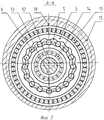
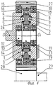
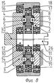
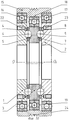
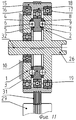
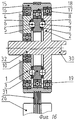
Изобретение иллюстрируется фиг.1-18. На фиг.1 показан в разрезе шариковый передающий узел по первому варианту изобретения, оформленный в виде модуля. На фиг.2 приведено сечение по А-А этого модуля. На фиг.3-9 показаны схемы получения на основе первого варианта изобретения шести различных передач. На фиг.10 дан разрез второго варианта шарикового передающего узла. Фиг.11-16 представляют различные схемы подключения этого передающего узла для получения различных передаточных отношений. Фиг.17 и 18 иллюстрируют возможность создания на основе заявляемого передающего узла трехскоростной коробки передач.The invention is illustrated in figures 1-18. Figure 1 shows in section a ball transmitting node according to the first embodiment of the invention, designed in the form of a module. Figure 2 shows a section along aa of this module. Figures 3 through 9 show production patterns of six different gears based on the first embodiment of the invention. 10 is a sectional view of a second embodiment of a ball transmitting assembly. 11-16 represent various wiring diagrams of this transmitting unit to obtain various gear ratios. 17 and 18 illustrate the possibility of creating on the basis of the inventive transmitting node three-speed gearbox.
Изображенные на фигурах 1, 2 и 10 модули могут выпускаться как самостоятельные изделия и затем встраиваться по аналогии с подшипником в различные механизмы для получения разных передаточных отношений. Модуль на фиг.1, 2 содержит три расположенных последовательно друг за другом диска 1, 2, 3. Диск 1 на своей плоской поверхности, обращенной к диску 3, имеет периодическую дорожку качения 4. Такая же дорожка качения 5, только с иным числом периодов выполнена на поверхности диска 3. Дорожки 4 и 5 образуют пару сопряженных дорожек, в пересечении которых размещена цепочка шариков 6. Шарики 6 находятся в контакте с обеими дорожками 4 и 5. На противоположной стороне диска 3 также выполнена периодическая дорожка качения 7, образующая с дорожкой качения 8 на диске 2 сопрягающуюся пару дорожек. В пересечении этих дорожек расположены шарики 9. Числа периодов дорожек качения 4, 5, 7 и 8 обозначим соответственно как Z4, Z5, Z7, Z8. Числа периодов сопрягающихся дорожек могут совпадать друг с другом и числом шариков, а также отличаться друг от друга на 1 и на 2. В первом случае дорожки представляют собой систему разнесенных по окружности замкнутых кольцевых канавок, и зацепление передает вращение без изменения скорости. Если числа периодов сопрягающихся дорожек отличаются на 1, то одна из дорожек - замкнутая периодически изогнутая канавка, а другая периодическая дорожка представляет собой систему разнесенных по окружности лунок или кольцевых канавок, число которых равно числу шариков. Возможен и третий вариант сочетания дорожек, когда число их периодов отличается на 2. Тогда число шариков на 1 меньше числа периодов одной дорожки и на 1 больше числа периодов другой. Обе дорожки качения представляют собой замкнутые периодически изогнутые канавки.The modules depicted in figures 1, 2, and 10 can be produced as separate products and then integrated by analogy with the bearing into various mechanisms to obtain different gear ratios. The module in figures 1, 2 contains three
Крайние диски 1 и 2 соосны и посажены с помощью подшипников 10 и 11 на вал 12, проходящий насквозь внутри модуля. Вал 12 имеет в своем среднем участке эксцентрик 13, на котором с помощью подшипника 14 посажен средний диск 3. Таким образом, средний диск 3 эксцентрично смещен относительно дисков 1 и 2. Снаружи модуль охватывает втулка 15, посаженная коаксиально крайним дискам 1 и 2 на подшипниках 16 и 17. Подшипники 16 и 17 обеспечивают возможность вращения охватывающей втулки 15 относительно оси OO1 передающего узла. На внутренней поверхности охватывающей втулки 15 выполнен эксцентричный участок 18, в котором на подшипнике 19 посажен средний диск 3. Эксцентрики 13 и 18 имеют одинаковый эксцентриситет и одинаковую направленность.The
Поскольку модуль должен работать в составе какого-либо приводного механизма, то должны быть предусмотрены элементы крепления его звеньев к звеньям внешнего механизма. На фиг.1 таким элементом для внутреннего вала 12 является шпонка 20 на одном конце вала и лыска 21 - на другом. Для связи дисков 1 и 2 со звеньями внешнего механизма предусмотрены отверстия 22 и 23 под крепежные винты. Связь наружной охватывающей втулки 15 целесообразно выполнить клиноременной передачей. Для этого на наружной поверхности втулки 15 предусмотрены гофры 24. Совершенно очевидно, что описываемые здесь элементы крепления не являются единственно возможными. Связь звеньев может быть выполнена любым известным в технике образом. Например, для втулки 15 это могут быть торцевые шлицы 25, показанные на нижней части чертежа. Вал 12 может быть выполнен полым, с элементами крепления на его внутренней поверхности.Since the module must work as part of any drive mechanism, elements should be provided for attaching its links to the links of the external mechanism. In figure 1, such an element for the
Обратимся теперь к фигурам 3-9, иллюстрирующим возможность получения на одном и том же модуле разных передаточных отношений в зависимости от подключения модуля. В передаче на фиг.3 ведущим звеном является внутренний вал 12 с эксцентриком 13. Диск 1 является реактивным, соединенным с корпусом. На фиг.3 это показано условно. Диск 2 соединен с ведомым валом 26. В этом случае наружная охватывающая втулка 15 будет звеном, связанным с внутренним валом 12 через эксцентрики 13 и 18 и подшипники 14, 19, и при вращении вала 12 будет свободно вращаться вместе с ним. Средний диск 3 кроме планетарного движения относительно оси передачи OO1 имеет возможность вращения вокруг собственной подвижной оси. Передача при таком включении модуля аналогична прототипу, и передаточное отношение механизма определится как i1=1/(1-Z5Z8/Z4Z7).Let us turn now to figures 3-9, illustrating the possibility of obtaining on the same module different gear ratios depending on the connection of the module. In the transmission of FIG. 3, the drive link is an
На фиг.4 ведущим звеном является наружная охватывающая втулка 15, для чего на ее наружной поверхности выполнен зубчатый венец 27, зацепляющийся с зубчатым колесом 28 на ведущем валу 29. Диск 1 является выходным звеном и соединен с ведомым валом 26. Диск 2 - реактивное неподвижное звено, соединенное с корпусом. Такое подключение модуля дает передачу с параллельными ведущим 29 и ведомым 26 валами. Передаточное отношение модуля равно i2=1/(1-Z7Z4/Z8Z5).In Fig. 4, the leading link is the external
Следует отметить, что передаточное отношение между ведущим валом 29 и ведомым 26 будет отличаться от i2 из-за дополнительной зубчатой передачи 28-27. В этой схеме ведущим валом может быть и вал 12 с эксцентриком 13. Из-за связи вала 12 и втулки 15 эксцентриками 13 и 18 обе передачи будут идентичны по принципу действия и дадут одинаковый результат - передаточное отношение модуля, равное i2.It should be noted that the gear ratio between the
В передаче на фиг.5 к ведущему валу 30 подсоединен диск 1, являющийся ведущим звеном. Реактивным звеном является соединенная с корпусом охватывающая втулка 15. Ведомое звено - диск 2 подсоединен к ведомому валу 26. Диск 3 в этой передаче посажен в неподвижной втулке 15 эксцентрично относительно дисков 1 и 2. Благодаря такой посадке он может только вращаться относительно оси, смещенной от оси OO1 передачи на расстояние, равное эксцентриситету. Передаточное отношение модуля равно i3=Z5·Z8/Z4·Z7.In the transmission of figure 5 to the
Подключение передающего узла на фиг.6 и 7 дает передаточное отношение i4=1. Ведущий вал 30 на фиг.6 одновременно подсоединен к диску 1 и к валу 12 с эксцентриком 13. Ведомым является диск 2. Весь модуль вращается в этом случае как единое целое, и момент к ведомому валу 26 передается через шариковое зацепление цепочки шариков 9 с дорожками качения 7 и 8.Connecting the transmitting node in Fig.6 and 7 gives the gear ratio i 4 = 1. The
На фиг.7 момент вращения от ведущего вала 30 к ведомому валу 26 передается через сквозной вал 12, соединенный с ними обоими. Все остальные звенья передачи вращаются вместе с ними как одно целое.7, the torque from the
В передаче на фиг.8 ведущим звеном модуля является диск 1, для чего он соединен с ведущим валом 30. Реактивным звеном является диск 2, соединенный с корпусом. Ведомым звеном является вал 12 с эксцентриком 13, соединенный с ведомым валом 26. Передаточное отношение модуля i5=1-Z7·Z4/Z8·Z5. Следует отметить, что в данной передаче ведомым звеном может быть и охватывающая втулка 15 с эксцентриком 18, так как втулка 15 и вал 12 связаны между собой эксцентриками 13 и 18. Для передачи вращения от втулки 15 к ведомому валу целесообразно воспользоваться дополнительной зубчатой или ременной передачей. В результате мы получим передачу с параллельными валами и передаточным отношением, отличающимся от i5 на передаточное отношение зубчатой или ременной передачи.In the transmission of Fig. 8, the drive link of the module is
И, наконец, при подключении модуля, как это показано на фиг.9, ведущим звеном будет соединенный с ведущим валом 30 диск 2, а реактивным звеном диск 1. Ведомым звеном в этом случае могут быть как охватывающая втулка 15, так и внутренний вал 12. Однако конструктивно осуществить отбор мощности от наружной втулки 15 проще. На фигуре 9 для этого наружная поверхность втулки 15 выполнена с зубчатым колесом 27, зацепляющимся с колесом 28 на ведомом валу 26. Передаточное отношение модуля i6=1-Z5·Z8/Z4·Z7, а передаточное отношение между ведомым валом 26 и ведущим валом 30 будет равно i6·Z28/Z27.And, finally, when the module is connected, as shown in Fig. 9, the drive link will be the
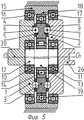
Как мы уже поясняли выше, в предлагаемом модуле внутренний вал связан с наружной втулкой с помощью среднего диска и одинаковых эксцентричных участков, выполненных на валу и внутри втулки. Это означает, что движение и функции этих связанных звеньев совершенно одинаковы. Этот факт позволяет создать модуль без внутреннего эксцентрика. Вариант модуля без внутреннего вала изображен на фиг.10. Диски 1 и 2 с общей осью вращения OO1 коаксиально посажены в наружной охватывающей втулке 15 с помощью подшипников 16 и 17. Внутренняя поверхность втулки 15 в средней области выполнена с эксцентричным участком 18. Внутри эксцентрика 18 на подшипниках 19 посажен средний диск 3. Ось вращения этого диска смещена относительно оси OO1 на величину эксцентриситета эксцентрика 18. Внутри всех дисков может быть выполнено сквозное отверстие. Наличие такого отверстия необходимо при использовании модуля, например, в приводах задвижек, где нужно иметь свободное пространство для хода штока задвижки. На плоских поверхностях дисков 1, 2 и 3, обращенных друг к другу, выполнены периодически изогнутые дорожки качения 4, 5, 7, 8. Обращенные друг к другу дорожки 4 и 5, 7 и 8 образуют сопрягающиеся пары, которые зацепляются друг с другом посредством двух цепочек шариков 6 и 9. Крепежные отверстия 22 и 23 в дисках 1 и 2 служат для подсоединения дисков к ведущему, ведомому валам или к неподвижному корпусу. Для этих же целей могут использоваться отверстия в дисках 1 и 2, которыми их можно жестко посадить на соосные валы. Наружную втулку 15 удобнее всего соединить с другим подвижным звеном передачей с несоосными валами (зубчатой, фрикционной или с гибкой связью). Поэтому при подключении втулки модуля к ведущему или ведомому валам получаем передачу с несоосными валами, а при подключении втулки к неподвижному корпусному элементу образуется передача с соосными валами. На фиг.10 в качестве гибкой связи предусмотрено использование клиноременной передачи, для чего на внешней поверхности втулки 15 выполнены гофры 24 для клинового ремня. Рассмотрим различные подключения модуля более подробно.As we have already explained above, in the proposed module, the inner shaft is connected to the outer sleeve using the middle disk and the same eccentric sections made on the shaft and inside the sleeve. This means that the movement and functions of these related links are exactly the same. This fact allows you to create a module without an internal eccentric. A module variant without an internal shaft is shown in FIG. 10.
На фиг.11 ведущим звеном является охватывающая втулка 15 с эксцентриком 18, для чего она соединена с ведущим валом 29 гибкой связью. На данном чертеже это клиновой ремень 31, передающий вращение ведущего вала 29 к втулке 15. Ведомым звеном является диск 2, соединенный с ведомым валом 26. Диск 1 является реактивным звеном, соединенным с неподвижным корпусом. Вал 26 в данном варианте выполнен сквозным, и его противоположный конец 32 с помощью подшипников 10 посажен в корпусном диске 1 для устранения консольной посадки вала 26. Передача по принципу действия не отличается от передаточного механизма на фиг.3, поэтому ее передаточное отношение равно i1. Если передача на фиг.3 может использоваться как для передачи вращения между соосными валами, так и для передачи вращения между параллельными валами, то передачу на фиг.11 наиболее эффективно использовать для передачи вращения между параллельными валами, используя для соединения наружной втулки 15 с ведущим валом 29 гибкую связь в виде клиноременной передачи 31 или, например, зубчатое соединение. Эта дополнительная связь позволяет корректировать передаточное отношение i1 до требуемых величин.11, the leading link is the
На фиг.12 показана схема включения второго варианта модуля, аналогичная схеме на фиг.4. Здесь ведущим звеном также является наружная охватывающая втулка 15, связанная клиновым ремнем 31 с ведущим валом 29. Реактивный диск и ведомый диск поменялись местами по сравнению с фиг.11. Диск 1 - ведомый, соединен с ведомым валом 26, а диск 2 - соединен с неподвижным корпусом. Соответственно передаточное отношение будет равно i2, так как оно определяется точно так же, как и для модуля на фиг.4.On Fig shows a diagram of the inclusion of the second variant of the module, similar to the circuit in figure 4. Here, the leading link is also the outer
Подключение модуля на фиг.13 аналогично схеме подключения на фиг.5. С неподвижным корпусом соединена наружная охватывающая втулка 15, диск 1 являемся ведущим звеном и соединен с ведущим валом 30, а диск 2 соединен с ведомым валом 26. Для дополнительного центрирования дисков 1 и 2 друг относительно друга вал 30 продлен по другую сторону диска и его противоположный конец на подшипнике 11 посажен в отверстии диска 2. Передаточное отношение модуля при такой схеме включения равно i3.Connecting the module in Fig.13 is similar to the connection diagram in Fig.5. The outer
На фиг.14 с ведущим валом 30 соединены одновременно и диск 1, и наружная охватывающая втулка 15 с эксцентричным участком 18. Схема аналогична схеме на фиг.6 и имеет передаточное отношение, равное 1. Поскольку модуль по второму варианту имеет внутреннее отверстие, то сквозь него всегда можно пропустить сквозной вал, который будет также передавать вращение без изменения скорости.In Fig. 14, both the
В схеме на фиг.15 ведущий вал 30 соединен с диском 1, диск 2 соединен с неподвижным корпусом, а вращение снимается с охватывающей втулки 15, для чего на ее наружной поверхности выполнен зубчатый венец 27, зацепляющийся с зубчатым колесом 28 на ведомом валу 26. Передаточное отношение модуля при такой схеме соединения равно i4 с корректировкой на передаточное отношение зубчатой пары 27-28.In the diagram of FIG. 15, the
И, наконец, схема на фиг.16 является зеркальным отображением схемы 15, где диски 1 и 2 поменялись функциями, диск 1 соединен с неподвижным корпусом, а диск 2 с ведущим валом 30. Момент вращения снимается также с втулки 15 с помощью клиноременной передачи. Передаточное отношение i5 корректируется за счет клиноременной передачи между втулкой 15 и ведомым валом 26. Вал 30 выполнен с участком 32, которым он с помощью подшипника 10 посажен в отверстии диска 1.And finally, the circuit in FIG. 16 is a mirror image of the
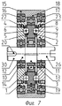
На фиг.17 и 18 показана возможность создания на основе первого варианта передающего модуля трехскоростной коробки передач. Фигуры 17 и 18 отличаются друг от друга только положением переключателей. В корпусе 32 на подшипниках 33 и 34 установлены входной 35 и выходной 36 валы коробки передач. Вал 36 напрямую соединен с диском 2 передающего модуля, который в данном случае является ведомым звеном. Входной вал 35 коробки передач соединен с диском 37, который имеет на своей боковой поверхности шлицы 38, для постоянного соединения со шлицами 39 скользящей переключающей втулки 40. На внутреннем валу 12 передающего модуля жестко посажен диск 41, имеющий на своей боковой поверхности шлицы 42 для соединения с другими шлицами 43 на скользящей переключающей втулке 40. Диск 1 передающего модуля также имеет шлицы на своей наружной боковой поверхности для соединения со шлицами 43 скользящей переключающей втулки 40. Втулка 40 является трехпозиционным переключателем и на верхней и нижней частях фиг.17 показана в двух крайних положениях переключения, а на фиг.18 показано среднее положение скользящей переключающей втулки 40. В одном крайнем положении втулка 40 соединяет входной вал 35 коробки передач с диском 1 передающего узла, а в другом крайнем положении соединяет этот же входной вал 35 через диск 41 с внутренним валом 12 передающего модуля. В промежуточном положении скользящей переключающей втулки 40, показанном на фиг.18, она соединяет входной вал 35 коробки передач одновременно с диском 1 и внутренним валом 12 передающего модуля. Наружная охватывающая втулка 15 передающего модуля с эксцентриковым участком 18 на внутренней поверхности посажена на подшипнике 17 на диске 2. В эксцентрике 18 на подшипнике 19 посажен средний диск 3. Охватывающая втулка 15 имеет шлицы 44. Еще один переключатель - скользящая втулка 45 на своей внутренней и внешней поверхностях имеет шлицы 46, 47 и 48. Диск 1 и корпус 32 также имеют шлицы 49 и 50. При зацеплении соответствующих шлицев скользящая переключающая втулка 45 может соединять с корпусом 32 либо диск 1, либо наружную втулку 15 передающего модуля. В третьем положении скользящей переключающей втулки 45, показанном на фиг.18, и диск 1 и охватывающая втулка 15 освобождаются от связи с корпусом 32. В принципе, возможно получение и других скоростей, но для этого вход и выход в модуле нужно менять местами, а такое переключение конструктивно сложно осуществить.On Fig and 18 shows the possibility of creating on the basis of the first embodiment of the transmitting module three-speed gearbox. Figures 17 and 18 differ from each other only in the position of the switches. In the
Работу передающего модуля рассмотрим на примере вышеописанной коробки передач, так как она позволяет показать работу модуля в разных схемах включения. Скользящая переключающая втулка 40 своими шлицами 39 постоянно зацеплена со шлицами 38 на диске 37, жестко связанном с входным валом 35.We consider the operation of the transmitting module using the example of the transmission described above, since it allows you to show the operation of the module in different switching circuits. Sliding switching
В левом положении скользящей переключающей втулки 40 (как это изображено в верхней части фигуры 17) шлицы 43 втулки зацеплены со шлицами 42 на диске 41. Тем самым входной вал 35 коробки передач соединяется с внутренним валом 12. При вращении входного вала вращается вал 12 с эксцентриком 13 и вовлекается в планетарное движение диск 3, который может также совершать вращение относительно собственной подвижной оси. Для работы передающего узла по этой схеме диск 1 должен быть заторможен, т.е. переключающая втулка 45 должна находиться в крайнем левом положении, соединяя с корпусом 32 диск 1. Планетарное движение диска 3 за счет взаимодействия цепочки шариков 6 с периодической дорожкой качения 5 на диске 3 и периодической дорожкой 4 на неподвижном диске 1 преобразуется во вращение диска 3 вокруг собственной оси. При этом одному обороту входного вала 35 будет соответствовать поворот диска 3 вокруг собственной оси на угол, определяемый соотношением периодов дорожек качения z4 и z5. В свою очередь, поворот диска 3 за счет взаимодействия дорожек 7 и 8 посредством цепочки шариков 9 преобразуется во вращение диска 2. Общее передаточное отношение u1 коробки передач при этом положении переключателей, определяемое как отношение скорости вращения выходного вала 36 к скорости вращения входного вала 35, составит u1=i3. Схема включения модуля при таком положении переключателей соответствует фиг.3.In the left position of the sliding switching sleeve 40 (as shown in the upper part of figure 17), the
Для получения другой передачи переключатель 40 следует перевести в крайнее правое положение, как это показано в нижней части фиг.17. В этом положении входной вал 35 коробки передач будет соединен с диском 1, делая его ведущим звеном модуля. Охватывающая втулка 15 с эксцентриком 18 должна быть неподвижной, для этого переключатель 45 переводится в крайнее правое положение, соединяя наружную охватывающую втулку 15 модуля с корпусом 32 и освобождая от связи с корпусом диск 1. В этом случае диск 3 получается посаженным в корпусе с возможностью вращения и может совершать только вращательное движение относительно своей оси, эксцентрично смещенной относительно оси дисков 1 и 2. Вращение диска 1 через цепочку шариков 6 и дорожки качения 4 и 5 передается к диску 3 с передаточным отношением, определяемым, как и для обычного зубчатого зацепления, как Z5/Z4. В свою очередь, вращение диска 3 передается к диску 2 через цепочку шариков 9 и дорожки качения 7 и 8 с передаточным отношением Z8/Z7. Общее передаточное отношение коробки передач u2 составит u2=Z5/Z4·Z8/Z7. Схема включения модуля соответствует фиг.5.To obtain another gear, the
В промежуточном положении переключающей втулки 40, как это показано на фиг.18, с входным валом 35 соединяются одновременно и диск 1, и внутренний вал модуля 12. Втулка 45 также занимает промежуточное положение, освобождая и диск 1 и охватывающую втулку 15 от связи с корпусом 32. Поскольку вращение входного вала передается одновременно и на диск 1 и на вал 12 с эксцентриком 13, то диски 1 и 3 будут вращаться совместно как одно целое и диск 3 будет вращаться как эксцентрик. При этом зацепление его дорожки 5 с дорожкой 4 на диске 1 будет разгружено от усилий, а зацепление дорожки качения 7 через шарики 9 с дорожкой качения 8 на диске 2 обеспечит вращение диска 2 с той же скоростью. Таким образом, вращение от входного вала 35 будет передаваться к выходному валу 36 без изменения скорости, Соответствующая этому случаю схема включения модуля показана на фиг.6. Следует отметить, что если снабдить указанную коробку передач еще одним переключателем, позволяющим соединять выходной вал 36 коробки передач с внутренним валом 12, то коробка будет иметь дополнительную повышающую передачу. Работу модуля в повышающем режиме рассмотрим ниже при обсуждении схем 8 и 9.In the intermediate position of the switching
Таким образом, мы рассмотрели здесь работу модуля при включении его по схемам на фиг.3, 5 и 6. Работа модуля при включении по схеме на фиг.4 отличается от работы модуля по схеме 5 только тем, что диск 2 заторможен, а диск 1 является ведомым звеном, с соответствующим изменением общего передаточного отношения модуля.Thus, we examined here the operation of the module when it is turned on according to the diagrams in Figs. 3, 5 and 6. The operation of the module when turned on according to the scheme in Fig. 4 differs from the operation of the module according to
Модули в схемах на фиг.8 и 9 работают как мультипликаторы, поэтому рассмотрим работу их более подробно. Вращение ведущего вала 30 на фиг.8 вызывает вращение диска 1. Зацепление цепочки шариков 6 с дорожками качения 4 и 5 вызовет вращение диска 3 вокруг собственной оси, а зацепление цепочки шариков 9 с дорожкой 7 на диске 3 и с дорожкой 8 на неподвижном диске 2 приведет к планетарному движению диска 3. Планетарное движение диска 3 преобразуется во вращение эксцентрика 13 и связанного с ним вала 12 с передаточным отношением i5=1-Z7·Z4/Z8·Z5. На фиг.9 ведущим является диск 2, а неподвижен диск 1. Поэтому передаточное отношение определится как i6=1-Z5·Z8/Z4·Z7. Кроме того, отбор момента вращения осуществляется не от центрального вала 12, а от кинематически связанной с ним охватывающей втулки 15.The modules in the circuits of Figs. 8 and 9 work as multipliers, so we will consider their operation in more detail. The rotation of the
Работа модуля по второму варианту изобретения полностью аналогична.The operation of the module according to the second embodiment of the invention is completely similar.
Как мы отмечали ранее, приведенные выше зависимости для определения передаточных отношений справедливы для случая, когда разница между числами периодов сопрягающихся дорожек равна 0, 1 или 2. Численная величина передаточного соотношения зависит от того, какая из дорожек в каждой сопрягающейся паре имеет большее число периодов. В качестве примера рассмотрим дорожки качения со следующими числами периодов: Z4=27, Z5=25, Z7=20, Z8=22. Этот модуль при разных схемах включения может давать передаточные отношения i1≈55, i2≈-54, i3≈1,018, i4=1, i5≈-0,0185, i6≈0,0181, где знак означает вращение в противоположном направлении. Если же соотношение чисел периодов во второй паре сопрягающихся дорожек поменять местами, т.е. Z7=22, a Z8=20, то получим другие значения передаточных отношений: i1≈6,32, i2≈-5,32, i3≈0,842, i4=1, i5≈-0,188, i6≈0,158. Если аналогичную перестановку сделать в первой паре, не изменяя значений второй пары, т.е. Z4=25, Z5=27, Z7=20, Z8=22, получим следующие передаточные числа: i1≈-5,32, i2≈6,32, i3≈1,188, i4=1, i5≈0,158, i6≈-0,188. По сравнению с предыдущим случаем передаточные отношения i1, i2 и i5, i6 поменялись местами, а i3 изменил свою величину. Поменяв местами числа периодов дорожек во второй паре, получим набор передаточных отношений, аналогичный первому, только i3 будет равно 0,982.As we noted earlier, the above dependencies for determining gear ratios are valid for the case when the difference between the numbers of periods of mating tracks is 0, 1, or 2. The numerical value of the gear ratio depends on which of the tracks in each mating pair has a greater number of periods. As an example, consider raceways with the following numbers of periods: Z 4 = 27, Z 5 = 25, Z 7 = 20, Z 8 = 22. This module with different switching schemes can give gear ratios i 1 ≈55, i 2 ≈-54, i 3 ≈ 1.018, i 4 = 1, i 5 ≈-0.0185, i 6 ≈ 0.0181, where the sign means rotation in the opposite direction. If the ratio of the number of periods in the second pair of mating tracks is interchanged, i.e. Z 7 = 22, a Z 8 = 20, then we get other values of the gear ratios: i 1 ≈ 6.32, i 2 ≈-5.32, i 3 ≈ 0.842, i 4 = 1, i 5 ≈-0.188, i 6 ≈0.158. If a similar permutation is done in the first pair, without changing the values of the second pair, i.e. Z 4 = 25, Z 5 = 27, Z 7 = 20, Z 8 = 22, we obtain the following gear ratios: i 1 ≈ -5.32, i 2 ≈6.32, i 3 ≈1.188, i 4 = 1, i 5 ≈ 0.158, i 6 ≈-0.188. Compared with the previous case, the gear ratios i 1 , i 2 and i 5 , i 6 are interchanged, and i 3 has changed its value. By interchanging the number of periods of the tracks in the second pair, we obtain a set of gear ratios similar to the first, only i 3 will be equal to 0.982.
Очевидно, что, варьируя числом периодов дорожек качения, можно перекрывать достаточно широкий диапазон передаточных отношений. Как показали наши расчеты, предлагаемый узел при варьировании чисел дорожек качения от 5 до 31 может перекрыть стандартный ряд передаточных отношений от 1,25 до 400.Obviously, by varying the number of periods of the raceways, it is possible to cover a fairly wide range of gear ratios. As our calculations showed, the proposed unit, when varying the number of raceways from 5 to 31, can overlap the standard range of gear ratios from 1.25 to 400.
Таким образом, имея в своем распоряжении набор дисков с четырьмя дорожками качения, мы можем создать шесть разных механизмов с отличающимися друг от друга передаточными отношениями. Как было показано выше, один шариковый передающий узел при одном направлении включения может давать три понижающих передачи, одна из которых может быть реверсивной, и одну повышающую передачу. Поэтому очень перспективно его использование в качестве модуля коробки передач, построенной на принципе перебора передаточных отношений. Так, на двух подобных модулях можно получить до 16 передач, часть из которых будет передачами обратного хода.Thus, having at our disposal a set of discs with four raceways, we can create six different mechanisms with different gear ratios. As shown above, one ball transmitting unit with one direction of inclusion can produce three downshifts, one of which can be reverse, and one upshift. Therefore, it is very promising to use it as a gearbox module, built on the principle of enumerating gear ratios. So, on two such modules you can get up to 16 gears, some of which will be reverse gears.
Claims (2)
Priority Applications (3)
| Application Number | Priority Date | Filing Date | Title |
|---|---|---|---|
| RU2004129188/11A RU2291993C2 (en) | 2004-10-04 | 2004-10-04 | Ball transmitting unit of variator |
| PCT/RU2005/000486 WO2006038833A1 (en) | 2004-10-04 | 2005-09-29 | Ball transmission unit for a speed converter (variants) and a step-by-step gear box based thereon |
| EP05802930A EP1803971A4 (en) | 2004-10-04 | 2005-09-29 | Ball transmission unit for a speed converter (variants) and a step-by-step gear box based thereon |
Applications Claiming Priority (1)
| Application Number | Priority Date | Filing Date | Title |
|---|---|---|---|
| RU2004129188/11A RU2291993C2 (en) | 2004-10-04 | 2004-10-04 | Ball transmitting unit of variator |
Publications (2)
| Publication Number | Publication Date |
|---|---|
| RU2004129188A RU2004129188A (en) | 2006-03-10 |
| RU2291993C2 true RU2291993C2 (en) | 2007-01-20 |
Family
ID=36115950
Family Applications (1)
| Application Number | Title | Priority Date | Filing Date |
|---|---|---|---|
| RU2004129188/11A RU2291993C2 (en) | 2004-10-04 | 2004-10-04 | Ball transmitting unit of variator |
Country Status (3)
| Country | Link |
|---|---|
| EP (1) | EP1803971A4 (en) |
| RU (1) | RU2291993C2 (en) |
| WO (1) | WO2006038833A1 (en) |
Families Citing this family (3)
| Publication number | Priority date | Publication date | Assignee | Title |
|---|---|---|---|---|
| CN104819277B (en) * | 2015-02-25 | 2017-09-15 | 佛山市诺尔贝机器人技术有限公司 | A kind of power input anti-self-rotating mechanism of many bent axle cycloid speed reducers |
| RU2600574C1 (en) * | 2015-04-20 | 2016-10-27 | Российская Федерация, от имени которой выступает Государственная корпорация по атомной энергии "Росатом" | Electric machine with multiplier |
| CN108351003A (en) * | 2015-11-09 | 2018-07-31 | 武藏精密工业株式会社 | Transmission device |
Family Cites Families (5)
| Publication number | Priority date | Publication date | Assignee | Title |
|---|---|---|---|---|
| SU684235A1 (en) * | 1978-03-30 | 1979-09-05 | Мукачевский Станкостроительный Завод Им. С.М.Кирова | Ball-type planetary gearing |
| JPH0762495B2 (en) * | 1985-06-27 | 1995-07-05 | 加茂精工株式会社 | Rolling ball type differential reduction mechanism |
| DE3801930A1 (en) * | 1987-11-19 | 1989-06-01 | Bollmann Hydraulik | BOLLMANN GEARBOX |
| RU2075671C1 (en) * | 1990-01-28 | 1997-03-20 | Могилевский Машиностроительный Институт | Ball planet gear |
| JP3348922B2 (en) * | 1992-10-16 | 2002-11-20 | 株式会社椿本チエイン | Reducer with two intersecting linear motion guide means |
-
2004
- 2004-10-04 RU RU2004129188/11A patent/RU2291993C2/en not_active IP Right Cessation
-
2005
- 2005-09-29 WO PCT/RU2005/000486 patent/WO2006038833A1/en active Application Filing
- 2005-09-29 EP EP05802930A patent/EP1803971A4/en not_active Withdrawn
Also Published As
| Publication number | Publication date |
|---|---|
| WO2006038833A1 (en) | 2006-04-13 |
| EP1803971A4 (en) | 2008-01-23 |
| RU2004129188A (en) | 2006-03-10 |
| EP1803971A1 (en) | 2007-07-04 |
Similar Documents
| Publication | Publication Date | Title |
|---|---|---|
| RU2484335C2 (en) | Variator | |
| CN106662230A (en) | Continuous variable transmission with uniform input-to-output ratio that is non-dependent on friction | |
| RU2506477C1 (en) | Planetary cycloidal reduction gear with preliminary stage | |
| RU2291993C2 (en) | Ball transmitting unit of variator | |
| KR101006779B1 (en) | Continuously Variable Transmission | |
| RU2402709C1 (en) | Planetary gear | |
| RU2270389C2 (en) | Gearbox | |
| WO2000063588A1 (en) | Reduction gearbox | |
| CN101126436A (en) | Harmonic teeth-driving stage-less speed variator | |
| US5308293A (en) | Variable speed drive transmission | |
| RU2313016C2 (en) | Eccentric planetary internal gearing | |
| KR20080053929A (en) | Gear mechanism, in particular linkage mechanism | |
| KR101027833B1 (en) | Continuously Variable Transmission | |
| KR200271928Y1 (en) | Improved transmission | |
| US4408502A (en) | Traction roller transmission | |
| RU2179272C1 (en) | "reduction gear - bearing" speed differential converter | |
| KR102206626B1 (en) | Continuously Variable Transmission shift system using rack and pinion gear system | |
| RU2009138288A (en) | WIDE-RANGE CONTINUOUS ACTUATOR (SUPERVARIATOR) | |
| RU2253778C1 (en) | Planet ball gearing | |
| RU54124U1 (en) | MECHANISM FOR TRANSFORMING ROTARY MOTION TO COMPLEX MOTION AND REVERSE | |
| RU2112170C1 (en) | Multi-output main plate-type frontal variable-speed drive | |
| RU2115846C1 (en) | Gear train | |
| SU1569469A1 (en) | Device for conversion of rotary motion | |
| RU2622178C1 (en) | High-torque variator of nonrycing type | |
| SU1249241A1 (en) | Reversing transfer gearbox |
Legal Events
| Date | Code | Title | Description |
|---|---|---|---|
| PC41 | Official registration of the transfer of exclusive right |
Effective date: 20130322 |
|
| MM4A | The patent is invalid due to non-payment of fees |
Effective date: 20141005 |