RU2273600C2 - Method and the device for exploitation of the tanks stations - Google Patents
Method and the device for exploitation of the tanks stations Download PDFInfo
- Publication number
- RU2273600C2 RU2273600C2 RU2003128974/12A RU2003128974A RU2273600C2 RU 2273600 C2 RU2273600 C2 RU 2273600C2 RU 2003128974/12 A RU2003128974/12 A RU 2003128974/12A RU 2003128974 A RU2003128974 A RU 2003128974A RU 2273600 C2 RU2273600 C2 RU 2273600C2
- Authority
- RU
- Russia
- Prior art keywords
- valve
- tank
- pipelines
- pipe
- bia
- Prior art date
Links
Images


Classifications
-
- C—CHEMISTRY; METALLURGY
- C12—BIOCHEMISTRY; BEER; SPIRITS; WINE; VINEGAR; MICROBIOLOGY; ENZYMOLOGY; MUTATION OR GENETIC ENGINEERING
- C12C—BEER; PREPARATION OF BEER BY FERMENTATION; PREPARATION OF MALT FOR MAKING BEER; PREPARATION OF HOPS FOR MAKING BEER
- C12C11/00—Fermentation processes for beer
- C12C11/003—Fermentation of beerwort
- C12C11/006—Fermentation tanks therefor
-
- Y—GENERAL TAGGING OF NEW TECHNOLOGICAL DEVELOPMENTS; GENERAL TAGGING OF CROSS-SECTIONAL TECHNOLOGIES SPANNING OVER SEVERAL SECTIONS OF THE IPC; TECHNICAL SUBJECTS COVERED BY FORMER USPC CROSS-REFERENCE ART COLLECTIONS [XRACs] AND DIGESTS
- Y10—TECHNICAL SUBJECTS COVERED BY FORMER USPC
- Y10T—TECHNICAL SUBJECTS COVERED BY FORMER US CLASSIFICATION
- Y10T137/00—Fluid handling
- Y10T137/0318—Processes
-
- Y—GENERAL TAGGING OF NEW TECHNOLOGICAL DEVELOPMENTS; GENERAL TAGGING OF CROSS-SECTIONAL TECHNOLOGIES SPANNING OVER SEVERAL SECTIONS OF THE IPC; TECHNICAL SUBJECTS COVERED BY FORMER USPC CROSS-REFERENCE ART COLLECTIONS [XRACs] AND DIGESTS
- Y10—TECHNICAL SUBJECTS COVERED BY FORMER USPC
- Y10T—TECHNICAL SUBJECTS COVERED BY FORMER US CLASSIFICATION
- Y10T137/00—Fluid handling
- Y10T137/4673—Plural tanks or compartments with parallel flow
- Y10T137/4857—With manifold or grouped outlets
-
- Y—GENERAL TAGGING OF NEW TECHNOLOGICAL DEVELOPMENTS; GENERAL TAGGING OF CROSS-SECTIONAL TECHNOLOGIES SPANNING OVER SEVERAL SECTIONS OF THE IPC; TECHNICAL SUBJECTS COVERED BY FORMER USPC CROSS-REFERENCE ART COLLECTIONS [XRACs] AND DIGESTS
- Y10—TECHNICAL SUBJECTS COVERED BY FORMER USPC
- Y10T—TECHNICAL SUBJECTS COVERED BY FORMER US CLASSIFICATION
- Y10T137/00—Fluid handling
- Y10T137/5762—With leakage or drip collecting
Landscapes
- Chemical & Material Sciences (AREA)
- Organic Chemistry (AREA)
- Engineering & Computer Science (AREA)
- General Health & Medical Sciences (AREA)
- Food Science & Technology (AREA)
- Biochemistry (AREA)
- Bioinformatics & Cheminformatics (AREA)
- General Engineering & Computer Science (AREA)
- Health & Medical Sciences (AREA)
- Genetics & Genomics (AREA)
- Life Sciences & Earth Sciences (AREA)
- Wood Science & Technology (AREA)
- Zoology (AREA)
- Pipeline Systems (AREA)
- Cleaning In General (AREA)
- Loading And Unloading Of Fuel Tanks Or Ships (AREA)
- Filling Or Discharging Of Gas Storage Vessels (AREA)
- Catching Or Destruction (AREA)
Abstract
Description
Область техникиTechnical field
Изобретение относится к способу эксплуатации резервуарных станций, жестко связанных с системами трубопроводов для жидкостей, в особенности для применения в установках, к которым предъявляются жесткие микробиологические требования в отношении качества и которые используются для обработки и транспортировки продукции в производстве продуктов питания и напитков, в фармацевтической промышленности и в биотехнологии.The invention relates to a method for operating reservoir stations tightly connected with piping systems for liquids, in particular for applications in installations that have stringent microbiological quality requirements and which are used for processing and transporting products in the production of food and beverages in the pharmaceutical industry and in biotechnology.
Микробиологические требования, предъявляемые сегодня к производственным установкам в сфере производства продуктов питания и напитков, в фармацевтической промышленности и в биотехнологии, возрастают по мере совершенствования измерительных методов для обнаружения микробиологических загрязнений и снижения пределов обнаружения разного рода веществ. В качестве типичного примера, могущего служить представителем всех прочих возможностей применения, далее будут рассматриваться процессы ферментации (например, бродильный участок на пивоваренных заводах). Здесь возникают проблемы, когда конструкция и расположение трубопроводов между ферментаторами и их периферией во взаимодействии с технологическими процессами создают условия, благоприятные для роста микробов. Применяющиеся в настоящее время схемы трубопроводов в сочетании с резервуарными станциями несут в себе потенциальные опасности этого рода, которые следует учитывать и по возможности исключать уже на первоначальной стадии проектирования таких установок. Ниже будут кратко описаны преобладающие в настоящее время концепции трубопроводов и будет показано, где возникает необходимость принятия мер с учетом все большего ужесточения микробиологических требований к качеству.The microbiological requirements for production plants in the food and beverage, pharmaceutical and biotechnology industries are increasing as measurement methods improve to detect microbiological contaminants and reduce the detection limits of various substances. As a typical example, which can serve as a representative of all other application possibilities, fermentation processes (for example, a fermentation site in breweries) will be further considered. Here problems arise when the design and arrangement of pipelines between the fermenters and their periphery in conjunction with technological processes create conditions favorable for the growth of microbes. The piping schemes currently used in combination with tank stations present potential hazards of this kind, which should be taken into account and, if possible, eliminated already at the initial design stage of such plants. Below we will briefly describe the currently prevailing pipeline concepts and show where the need arises to take measures in view of the increasing tightening of microbiological quality requirements.
Уровень техникиState of the art
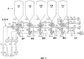
Соответствующее и, пожалуй, наиболее распространенное известное техническое решение в рассматриваемой области рассмотрено ниже на примере резервуарной станции 1 (Фиг.1) пивоваренного завода, с пятью ферментаторами 1.1, ..., 1.n. Количество ферментаторов можно неограниченно увеличивать, поэтому пятый ферментатор обозначен 1.n. Каждый из ферментаторов соединен соответственно с первым заливочным трубопроводом 2.1 (т.н. функциональным трубопроводом) для заливки F1 (сусло WZ) и вторым заливочным трубопроводом 2.2 для заливки F2 (дрожжи Н), сливным трубопроводом 3 для слива Е1 (молодое пиво J) или для слива Е2 (спуск дрожжей Н*), промывочным трубопроводом 4 для промывки резервуара и труб (моющий раствор R) и спускным трубопроводом 12 для промывки труб R2 (моющий раствор R). В точках присоединения, в которых могут соприкасаться несовместимые вещества (продукт Р, как общий термин, заменяет, например, сусло WZ или дрожжи Н или молодое пиво J и, соответственно, моющий раствор R), установлены так называемые предохраняющие от смешивания клапаны. В рассматриваемом примере это вторые клапаны 7.2.1.1-7.2.1.n, которые отделяют выпускные патрубки 8.1.1*-8.1.n*, в которых находится содержимое соответствующих резервуаров 1.1, ..., 1.n, от ведущих к так называемому клапанному блоку VB сливных трубопроводов 8.1.1...8.1.n. В примере, изображенном на Фиг.1, показан уже усовершенствованный вариант системы трубопроводов, более простые варианты кратко охарактеризованы ниже.The corresponding and perhaps the most common known technical solution in the field under consideration is discussed below on the example of the tank station 1 (Figure 1) of the brewery, with five fermenters 1.1, ..., 1.n. The number of fermenters can be increased indefinitely, so the fifth fermenter is designated 1.n. Each of the fermenters is connected respectively to the first filling pipe 2.1 (the so-called functional pipe) for pouring F1 (wort WZ) and the second filling pipe 2.2 for pouring F2 (yeast H), drain pipe 3 for draining E1 (young beer J) or for draining E2 (drain of yeast H *), flushing
Простейшая система трубопроводов, не изображенная на чертеже, состоит в том, что функции заливки F1, F2, слива Е1, Е2 и промывки резервуаров и труб R1, R2 объединены в центральном клапанном блоке VB, а выпускные трубы 8.1.1*-8.1.n* различной длины ведут к этому клапанному блоку VB без промежуточных вторых клапанов 7.2.1.1...7.2.1.n, упомянутых выше. Хотя такое решение позволяет получить относительно короткое расстояние а между так называемыми перемычками 9.1.1...9.1.n+1 клапанного блока VB, но зато длина части выпускных труб 8.1.*-8.1.n* получается очень длинной. При такой схеме выпускные трубы 8.1.1*-8.1.n* и соответствующие им перемычки 9.1.1...9.1.n клапанного блока VB являются частью соответствующих резервуаров 1.1, ..., 1.n. Недостаток такой системы заключается в том, что содержимое каждого резервуара 1.1, ..., 1.n одновременно является содержимым выпускной трубы 8.1.1*...8.1.n* этого резервуара и подключенной перемычки 9.1.1...9.1.n. При такой геометрии и таком построении системы этот объем лишь в очень ограниченной степени участвует в технологическом процессе (в данном примере в процессе брожения), происходящем в рассматриваемом резервуаре 1.1, ..., 1.n, вследствие чего массообмен там происходит также лишь в ограниченной мере.The simplest piping system, not shown in the drawing, consists in the fact that the pouring functions F1, F2, drain E1, E2 and flush the tanks and pipes R1, R2 are combined in the central valve block VB, and the exhaust pipes 8.1.1 * -8.1.n * of various lengths lead to this valve block VB without intermediate second valves 7.2.1.1 ... 7.2.1.n mentioned above. Although this solution allows you to get a relatively short distance a between the so-called jumpers 9.1.1 ... 9.1.n + 1 of the valve block VB, but the length of the part of the exhaust pipes 8.1. * - 8.1.n * is very long. With this scheme, the exhaust pipes 8.1.1 * -8.1.n * and the corresponding jumpers 9.1.1 ... 9.1.n of the valve block VB are part of the corresponding tanks 1.1, ..., 1.n. The disadvantage of such a system is that the contents of each tank 1.1, ..., 1.n are at the same time the contents of the exhaust pipe 8.1.1 * ... 8.1.n * of this tank and the connected jumper 9.1.1 ... 9.1.n . With such geometry and such construction of the system, this volume is only to a very limited extent involved in the technological process (in this example, in the fermentation process) occurring in the tank 1.1, ..., 1.n under consideration, as a result of which mass transfer there also occurs only in a limited least.
Упомянутые выше недостатки можно несколько смягчить, если проложить выпускные трубы 8.1.1*...8.1.n* к клапанному блоку VB с как можно более крутым уклоном. При этом благодаря газовым пузырям, поднимающимся к соответствующему резервуару 1.1, ..., 1.n из его спускной трубы 8.1.1*...8.1.n*, возникает некоторая конвекция и, следовательно, перемешивание, способствующее массообмену.The disadvantages mentioned above can be somewhat mitigated by laying the exhaust pipes 8.1.1 * ... 8.1.n * to the VB valve block with the most steep slope. In this case, due to gas bubbles rising to the corresponding reservoir 1.1, ..., 1.n from its downpipe 8.1.1 * ... 8.1.n *, some convection occurs and, consequently, mixing, which facilitates mass transfer.
Главная проблема жесткого соединения с клапанным блоком VB резервуара 1.1, ..., 1.n, который при этом не отделим от своей выпускной трубы 8.1.1*...8.1.n*, ведущей к клапанному блоку VB, состоит, однако, в первую очередь в том, что невозможно осуществить вытеснение продукта Р и отдельную промывку R1 выпускных труб 8.1.1*...8.1.n* и соответствующих перемычек 9.1.1...9.1.n.The main problem with the hard connection to the valve block VB of the tank 1.1, ..., 1.n, which is not separable from its exhaust pipe 8.1.1 * ... 8.1.n *, which leads to the valve block VB, consists, however, first of all, the fact that it is impossible to displace the product P and separately rinse R1 the exhaust pipes 8.1.1 * ... 8.1.n * and the corresponding jumpers 9.1.1 ... 9.1.n.
Если, например, при такой системе резервуар 1.2 будет заполнен суслом WZ, то одновременно заполнятся конец заливной трубы (в данном примере первой заливной трубы 2.1) между клапанами V12 и V16 клапанного блока VB и конец перемычки 9.1.2 между клапаном V12 и клапаном V52. Содержимое этих участков практически невозможно вытеснить, даже и в том случае, если проложить так называемое вытеснение А1, ведущее от трубопровода вытеснения А6 в резервуар, в данном примере в резервуар 1.2. Вследствие этого в перемычке 9.1.2 образуется неопределимая смесь из сусла WZ, дрожжей Н (если после заливки сусла была введена добавка дрожжей) и вытесняющей воды W. Эта смесь останется там до тех пор, пока через несколько дней резервуар 1.2 не будет опорожнен и очищен.If, for example, with such a system, tank 1.2 is filled with WZ, then the end of the filler pipe (in this example, the first filler pipe 2.1) between the valves V 12 and V 16 of the valve block VB and the end of the bridge 9.1.2 between the valve V 12 and are filled valve V 52 . The contents of these sections are almost impossible to displace, even if the so-called displacement A1 is laid, leading from the displacement pipeline A6 to the tank, in this example, to the tank 1.2. As a result, in jumper 9.1.2 an indefinable mixture is formed from wort WZ, yeast H (if yeast was added after the wort was added) and displacing water W. This mixture remains there until after a few days the reservoir 1.2 is empty and cleaned .
Из технологии пивоварения известно, что в сусле WZ могут содержаться микроорганизмы, которые не могут быть обнаружены, пока их подавляет активная среда дрожжей. Однако эти дремлющие микроорганизмы начинают размножаться, как только для этого возникают благоприятные условия. Такие условия могут возникать, например, вследствие того, что в результате ежедневной горячей промывки (85-90°С) функциональных трубопроводов смесь из сусла WZ, дрожжей Н и вытесняющей воды W, находящаяся в соответствующей перемычке 9.1.1...9.1-n, нагревается. Температура там легко может повышаться до 35°С, вследствие чего, в зависимости от штамма микробов, возникают оптимальные условия для их размножения, особенно, если принять во внимание, что после достижения конечной стадии брожения дрожжи Н теряют активность и осаждаются. Их подавляющее действие на микроорганизмы при этом прекращается. Такие бесконтрольно размножающиеся и практически неустранимые микроорганизмы при последующих операциях опорожнения, извлечения дрожжей и перекачки переносятся в другие резервуары и на другие производственные участки и загрязняют продукт.From brewing technology, it is known that WZ must contain microorganisms that cannot be detected until they are suppressed by the active environment of the yeast. However, these dormant microorganisms begin to multiply as soon as favorable conditions arise for this. Such conditions may arise, for example, due to the fact that as a result of daily hot washing (85-90 ° С) of functional pipelines, a mixture of wort WZ, yeast N and displacing water W located in the corresponding jumper 9.1.1 ... 9.1-n Heats up. The temperature there can easily rise to 35 ° C, as a result of which, depending on the strain of microbes, optimal conditions arise for their reproduction, especially if we take into account that after reaching the final stage of fermentation, yeast N lose activity and precipitate. Their overwhelming effect on microorganisms at the same time ceases. Such uncontrollably propagating and practically unremovable microorganisms during subsequent operations of emptying, extracting yeast and pumping are transferred to other tanks and to other production sites and pollute the product.
Вариант, изображенный на Фиг.1, усовершенствованный по сравнению с описанным выше более простым вариантом системы трубопроводов, позволяет отдельно осуществить промывку R1 участка выпускного трубопровода 8.1.1**...8.1.n** и примыкающей к нему выпускной трубы 8.1.1...8.1.n независимо от промывки соответствующего резервуара 1.1,...1.n, производимой через подводящий трубопровод промывки резервуара 11.1.1...11.1.n. Это достигается с помощью первого клапана 7.1.1.1...7.1.1.n и второго клапана 7.2.1.1...7.2.1.n, из которых первый отделяет первый участок выпускного трубопровода 8.1.1**...8.1.n** от трубопровода промывки 4, а второй отделяет этот участок от следующего за ним выпускного трубопровода 8.1.1...8.1.n. Тем самым эти клапаны отделяют соответствующий выпускной трубопровод резервуара 8.1.1*...8.1.n* от упомянутых выпускных трубопроводов 8.1.1**...8.1.n**.The variant depicted in FIG. 1, improved in comparison with the simpler version of the piping system described above, allows separately flushing R1 of the section of the exhaust pipe 8.1.1 ** ... 8.1.n ** and the adjacent exhaust pipe 8.1.1 ... 8.1.n, regardless of the flushing of the corresponding tank 1.1, ... 1.n, carried out through the tank flushing inlet pipe 11.1.1 ... 11.1.n. This is achieved using the first valve 7.1.1.1 ... 7.1.1.n and the second valve 7.2.1.1 ... 7.2.1.n, of which the first separates the first section of the exhaust pipe 8.1.1 ** ... 8.1. n ** from the
При соответствующем построении периферии установки и если позволяет временной график производственного процесса, такую промывку труб R1 можно производить по перемычкам после каждой операции заливки и опорожнения или один раз в день путем поочередного переключения всех выпускных трубопроводов 8.1.1...8.1.n совместно с перемычками 9.1.1...9.1.n в каждой фазе промывки системы резервуаров и трубопроводов.With the appropriate construction of the installation periphery and if the time schedule of the production process allows, such flushing of the R1 pipes can be done with jumpers after each pouring and emptying operation or once a day by switching all exhaust pipelines 8.1.1 ... 8.1.n in series with the jumpers 9.1.1 ... 9.1.n in each phase of flushing the tank system and pipelines.
Промывка перемычки 9.1.3 может производиться, например, следующим образом.Flushing jumper 9.1.3 can be performed, for example, as follows.
Моющий раствор R подводится в процессе промывки труб R1 в промывочный трубопровод 4. Он поступает через первый клапан 7.1.1.3 в участок выпускной трубы 8.1.3**, а оттуда через второй клапан 7.2.1.3 в выпускную трубу 8.1.3 и, наконец, в перемычку 9.1.3. Оттуда через клапан V53 клапанного блока VB моющий раствор поступает в трубопровод 4 и через второй насос 14 удаляется из изображенной системы труб.During the washing of pipes R1, the washing solution R is supplied to the
Трубопроводы 10.1...10.3, которые пересекают перемычки 9.1.1...9.1.n+1, могут очищаться через промывку труб R2. Они заполняются моющим раствором R через вторую подводящую промывочную трубу 5.2 посредством поочередного включения клапанов, не обозначенных более подробно. При этой промывке труб R2 моющий раствор R выводится из системы труб через сливной трубопровод промывки труб 12. Запорный клапан 15 позволяет производить промывку резервуаров и перемычек R1 через линию промывки 4 без одновременного заполнения детергентом этой линии между резервуаром 1.1 и вторым насосом 14.Pipelines 10.1 ... 10.3 that cross the jumpers 9.1.1 ... 9.1.n + 1 can be cleaned by flushing pipes R2. They are filled with washing solution R through the second inlet washing pipe 5.2 by alternately turning on valves, not indicated in more detail. In this washing of pipes R2, the washing solution R is discharged from the pipe system through the drain
Промывка четвертой линии 10.4 (промывка труб R2), которая через первый насос 13 выходит в сливную трубу 3, производится путем подачи моющего раствора R в первый подающий трубопровод промывки труб 5.1. По пути к четвертому трубопроводу 10.4 моющий раствор R сначала проходит через установленный перед матрицей клапанов второй клапан V401, а затем через первый клапан V40.The washing of the fourth line 10.4 (pipe washing R2), which through the
Из вышеприведенного краткого описания порядка промывки системы трубопроводов и резервуарной станции 1 видно, что путем установки большого количества клапанов и дополнительных отрезков трубопроводов могут быть промыты в основном все участки разветвленной сети трубопроводов.From the above brief description of the flushing procedure for the piping system and
Однако и в изображенной на Фиг.1 системе трубопроводов, выполненной по известной схеме, имеются невытесняемые участки внутри клапанного блока VB. Невытесненный продукт Р вымывается при очередной промывке, что приводит к потерям продукта. На примере упомянутой выше заливки в резервуар 1.2 сусла WZ через первый трубопровод заливки 2.1 покажем вкратце, в чем состоят эти потери продукта. При подаче вытесняющей воды по ходу вытеснения А1 через трубопровод вытеснения 6 то сусло WZ, которое находится в выпускных трубопроводах 8.1.2** и 8.1.2 и примыкающей перемычке 9.1.2 до клапана V42, вытесняется в резервуар 1.2. Содержимое перемычки 9.1.2 на участке между клапанами V42 и V52, а также содержимое трубопровода 10.1 на участке между клапанами V12 и V16 упомянутое выше вытеснение А1 через трубопровод вытеснения А6 не охватывает. Таким образом, сусло, находящееся в этих участках трубопровода, теряется.However, in the piping system shown in FIG. 1, according to the known scheme, there are non-extruded sections inside the valve block VB. Unpolluted product P is washed out during the next wash, which leads to product loss. Using the aforementioned pouring of WZ wort into reservoir 1.2 through the first pouring pipeline 2.1, we briefly show what these product losses are. When displacing water is supplied along displacement A1 through displacement line 6, then the wort WZ, which is located in the discharge pipes 8.1.2 ** and 8.1.2 and the adjacent jumper 9.1.2 to valve V 42 , is displaced into reservoir 1.2. The contents of the jumper 9.1.2 in the area between the valves V 42 and V 52 , as well as the contents of the pipeline 10.1 in the area between the valves V 12 and V 16, the aforementioned displacement A1 through the displacement pipe A6 does not cover. Thus, the wort located in these sections of the pipeline is lost.
Посредством затрат на дополнительные конструктивные элементы, позволяющие осуществить так называемое «обратное вытеснение», можно сократить и эти потери в упомянутых выше участках трубопроводов, связанных с первым трубопроводом заливки 2.1. Однако обычно такие меры оправдывают себя только при очень длинных участках труб внутри клапанного блока VB.Due to the costs of additional structural elements that allow the so-called “backward displacement”, these losses can also be reduced in the above-mentioned sections of pipelines associated with the first filling pipeline 2.1. However, usually such measures only work for very long pipe sections inside the VB valve block.
Известны также другие способы дальнейшего уменьшения потерь продукта. Один из этих способов состоит в том, чтобы осуществить во всех рассматриваемых трубопроводах т.н. «кольцевое вытеснение», при котором в системе трубопроводов не возникает сколько-нибудь заметных «мертвых концов». Как «обратное вытеснение», так и «кольцевое вытеснение» требуют в любом случае значительных капиталовложений. При этих способах промывка перемычек клапанного блока и отходящих от резервуаров выпускных трубопроводов всегда производится независимо от промывки резервуаров, исключительно как промывка труб. Чтобы избежать ограничений по времени, так как промывка резервуара загружает выпускную линию, рециркуляционная линия промывки резервуара подключается непосредственно к резервуару без использования выпускной линии.Other methods are also known to further reduce product losses. One of these methods is to implement in all considered pipelines the so-called “Ring displacement”, in which there are no noticeable “dead ends” in the piping system. Both “backward crowding out” and “circular crowding out” require significant investment in any case. With these methods, flushing of the jumpers of the valve block and exhaust pipelines leaving the reservoirs is always carried out independently of the flushing of the reservoirs, exclusively as flushing of the pipes. To avoid time limitations, since flushing the tank loads the outlet line, the recirculation line for flushing the tank is connected directly to the tank without using the outlet line.
Устройство для реализации упомянутого выше «кольцевого вытеснения» подлежит определенным ограничениям, так как кольцевой трубопровод на клапанном блоке VB в настоящее время может использоваться только для одного процесса промывки. Ограничений можно избежать только путем согласованного по времени управления производством или путем установки второго кольцевого трубопровода.The device for implementing the aforementioned “annular displacement” is subject to certain restrictions, since the annular pipe on the valve block VB can currently be used for only one washing process. Limitations can only be avoided by time-coordinated production management or by installing a second ring pipeline.
В заключение перечислим основные недостатки, свойственные всем системам резервуарных станций, жестко связанным трубопроводами с клапанными блоками VB, в которых большое количество клапанов расположено в форме матрицы:In conclusion, we list the main disadvantages inherent in all systems of reservoir stations, rigidly connected by pipelines with valve blocks VB, in which a large number of valves are located in the form of a matrix:
• За точками разветвления таких клапанов находятся участки трубопроводов, из которых обычным образом нельзя вытеснить продукт Р (примеры: участок выпускного трубопровода 8.1.2**; участок первого трубопровода 10.1 между V12 и V16, перемычка 9.1.2 между V42 и V52).• There are sections of pipelines beyond the branch points of these valves from which product P cannot normally be forced out (examples: section of the discharge pipe 8.1.2 **; section of the first pipe 10.1 between V 12 and V 16 , jumper 9.1.2 between V 42 and V 52 ).
• В так называемых «мертвых концах» часто образуется неопределенная смесь различных продуктов Р (WZ, H, J) и вытесняющей воды W.• In the so-called "dead ends" often an undefined mixture of various products P (WZ, H, J) and displacing water W.
• Невытесненный продукт теряется самое позднее при очередной промывке.• Unpolluted product is lost at the latest during the next flush.
• Неопределенные смеси загрязняют требуемый продукт Р, в котором могут возникать неконтролируемые процессы, в частности, нежелательный рост микроорганизмов.• Uncertain mixtures contaminate the desired product P, in which uncontrolled processes can occur, in particular, undesirable growth of microorganisms.
• Вследствие повышения температуры, например, в результате горячей промывки, в перемычках клапанного блока создается среда, способствующая нежелательному росту микроорганизмов.• Due to a rise in temperature, for example, as a result of hot flushing, a medium is created in the bulkheads of the valve block that promotes unwanted growth of microorganisms.
• Продукт Р, содержащийся в клапанных блоках, в особенности расположенных горизонтально, и при длинных линиях не участвует в технологических процессах, происходящих в резервуаре, а следовательно, в этих участках трубопровода не происходит массообмена или он незначителен.• Product R contained in valve blocks, especially those located horizontally, and with long lines, does not participate in technological processes occurring in the tank, and therefore, mass transfer does not occur in these sections of the pipeline or it is insignificant.
• Чтобы в описанных выше классических вентильных матрицах избежать появления невытесненного продукта, сократить потери и обеспечить возможность отдельной промывки этих участков даже при заполненном резервуаре, нужны очень большие затраты на периферии вентильной матрицы. Такие затраты в большинстве случаев оказываются финансово неприемлемыми, и это приводит к появлению плохо обозримых и трудно обслуживаемых систем. По этим причинам при практическом решении проблем принимаются компромиссные решения, содержащие более или менее явно выраженные ограничения.• In order to avoid the appearance of a displaced product in the classical valve arrays described above, to reduce losses and to provide the possibility of separate washing of these areas even when the tank is full, very high costs are required at the periphery of the valve arrays. Such costs in most cases are financially unacceptable, and this leads to the emergence of poorly visible and difficult to maintain systems. For these reasons, in the practical solution of problems, compromise decisions are made containing more or less explicit limitations.
• Воздух, проникающий при промывке резервуара в его выпускной патрубок и в примыкающий к нему выпускной трубопровод в соединении с перемычкой, не позволяет как следует промыть систему трубопроводов.• The air that enters when flushing the tank into its outlet pipe and into the outlet pipe adjacent to it in connection with the jumper prevents the pipe system from being properly flushed.
Раскрытие изобретенияDisclosure of invention
Задачей изобретения является создание способа эксплуатации резервуарных станций, жестко соединенных с системами трубопроводов для жидкостей, удовлетворяющего высоким микробиологическим требованиям к качеству и позволяющего реализовать устройство для его осуществления проще, чем с аналогичными известными устройствами.The objective of the invention is to provide a method of operating reservoir stations, rigidly connected to piping systems for liquids, satisfying high microbiological quality requirements and making it possible to implement a device for its implementation easier than with similar known devices.
Эта задача решается способом по п.1 формулы изобретения. Устройство для реализации способа характеризуется признаками независимого п.2 формулы, тогда как предпочтительные формы исполнения предлагаемого устройства являются предметом дополнительных пунктов формулы изобретения.This problem is solved by the method according to
Идея изобретения находит свое воплощение в резервуарном парке, состоящем, по меньшей мере, из одного резервуара, к которому подводятся жидкости из системы трубопроводов, из которого жидкости отводятся в систему трубопроводов и в котором подвод жидкостей к данному резервуару и отвод жидкостей из него осуществляются снизу. Отличительная черта изобретения состоит в том, что подводимые или отводимые жидкости протекают через камеру, расположенную под соответствующим резервуаром и непосредственно связанную с его содержимым, и что жидкость в этой камере в непосредственной близости от ее границы по желанию может быть отделена от подведенных к этой камере трубопроводов переключающим устройством, предохраняющим от смешивания.The idea of the invention is embodied in a tank farm consisting of at least one tank, to which fluids are supplied from the piping system, from which fluids are discharged into the piping system, and in which fluids are supplied to and discharged from the tank from below. A distinctive feature of the invention is that the supplied or discharged liquids flow through a chamber located under the corresponding reservoir and directly connected with its contents, and that the liquid in this chamber in the immediate vicinity of its boundary can optionally be separated from pipelines connected to this chamber mixing protection device.
Благодаря непосредственному подводу всех функциональных трубопроводов к расположенной под соответствующим резервуаром камере, которая непосредственно соединена с содержимым резервуара, устраняются все недостатки, перечисленные выше при описании известных из уровня техники решений. Не образуется никаких невытесненных участков в отходящем от резервуара выпускном трубопроводе. Содержимое трубопроводов, которые в непосредственной близости от границы камеры по желанию отделяются от него переключающим устройством, предохраняющим от смешивания, может быть вытеснено в резервуар посредством обратного вытеснения, так что потери продукта сводятся к минимуму или вообще исключаются. Между находящейся в камере жидкостью и содержимым резервуара происходит интенсивный массообмен, так что в ней не могут происходить никакие неконтролируемые процессы. Заметного нагрева жидкости, находящейся в камере под резервуаром, вследствие горячей промывки подключенных к этой камере функциональных трубопроводов не происходит, так как благодаря интенсивному обмену между содержимым резервуара и содержимым камеры обеспечивается отвод выделяющегося тепла.Thanks to the direct supply of all functional pipelines to the chamber located under the corresponding reservoir, which is directly connected to the contents of the reservoir, all the disadvantages listed above in the description of solutions known from the prior art are eliminated. No unplaced sections are formed in the outlet pipe extending from the tank. The contents of pipelines, which in the immediate vicinity of the chamber boundary are optionally separated from it by a switching device protecting against mixing, can be displaced into the tank by means of backward displacement, so that product losses are minimized or even eliminated. Intense mass transfer occurs between the liquid in the chamber and the contents of the reservoir, so that no uncontrolled processes can occur in it. Significant heating of the liquid located in the chamber under the tank does not occur due to hot washing of the functional pipelines connected to this chamber, since due to the intensive exchange between the contents of the tank and the contents of the chamber, the heat generated is removed.
Реализация способа предполагает наличие резервуарной станции, состоящего, по меньшей мере, из одного резервуара, соединенного с системой трубопроводов, состоящей, по меньшей мере, из одного трубопровода. Существенными для изобретения признаками этого устройства являются стойка распределительных клапанов, вделанная в днище соответствующего резервуара, выполняемая предпочтительно в виде вытянутого в длину полого корпуса, ориентированная преимущественно вертикально и имеющая отверстия для соединения своей внутренней полости с каждым из трубопроводов, и предохраняющие от смешивания в окрестности своего седла клапаны, устанавливаемые в каждом соединении между трубопроводом и относящимся к нему присоединительным отверстием и переключающими эти соединения в непосредственной близости от полого корпуса.The implementation of the method involves the presence of a tank station, consisting of at least one tank connected to a piping system consisting of at least one pipeline. Significant for the invention features of this device are a distributor valve rack embedded in the bottom of the corresponding reservoir, preferably made in the form of a hollow body elongated in length, oriented mainly vertically and having openings for connecting its internal cavity with each of the pipelines, and preventing mixing in the vicinity of its valve seats installed in each connection between the pipeline and its associated connecting hole and switch these compounds in the immediate vicinity of the hollow body.
Вытянутый в длину полый корпус является как бы очень короткой выпускной трубой резервуара. Он позволяет по желанию путем переключения отделять присоединенные к нему трубопроводы в непосредственной близости от своей внутренней границы с помощью соответствующих, предохраняющих от смешивания клапанов. Благодаря этому не образуется невытесненных участков в трубопроводах. Продукт из участка трубопровода за точкой разветвления после соответствующего клапана можно путем «обратного вытеснения» вытеснить в полый корпус, а следовательно, в непосредственно примыкающий к нему резервуар. Предложенное устройство занимает мало места, требует небольших затрат, хорошо обозримо и удобно в обслуживании. Благодаря простоте монтажа и обозримой структуре предлагаемое устройство меньше подвержено отказам.The elongated hollow body is a very short outlet pipe of the tank. It allows you to optionally by switching to separate the pipelines connected to it in the immediate vicinity of its internal border using appropriate valves preventing mixing. Due to this, no displaced sections are formed in the pipelines. The product from the pipeline section beyond the branch point after the corresponding valve can be displaced into the hollow body, and, therefore, into the tank immediately adjacent to it. The proposed device takes up little space, requires little cost, is clearly visible and easy to maintain. Due to the ease of installation and the visible structure of the proposed device is less prone to failure.
Так как днище резервуара, как правило, сужается книзу, полый корпус устанавливается в самой низкой точке днища. Поскольку днище резервуара обладает осевой симметрией относительно его продольной оси, как это в большинстве случаев имеет место на практике, продольная ось полого корпуса коаксиальна относительно продольной оси резервуара. Полый корпус получается особенно простым, если его выполнять в виде цилиндрической трубки, как это будет предложено далее.Since the bottom of the tank, as a rule, tapers down, the hollow body is installed at the lowest point of the bottom. Since the bottom of the tank has axial symmetry about its longitudinal axis, as is the case in most cases, the longitudinal axis of the hollow body is coaxial with respect to the longitudinal axis of the tank. The hollow body is especially simple if it is made in the form of a cylindrical tube, as will be proposed below.
Полый корпус можно полностью опорожнить и хорошо промыть, если его нижний конец, противоположный днищу резервуара, соединить с промывочным трубопроводом.The hollow body can be completely emptied and rinsed well if its lower end, opposite the bottom of the tank, is connected to the flushing pipe.
Система трубопроводов для нескольких резервуаров становится особенно простой и наглядной, если, как это предусмотрено в первом предложении, трубопроводы первой группы и трубопроводы второй группы, проложенные в каждой группе один под другим, будут попарно располагаться с двух сторон полого корпуса в двух параллельных плоскостях относительно друг друга и относительно продольной оси полого корпуса и проходить мимо него. Такое расположение всегда предпочтительно, если резервуары расположены в ряд.The piping system for several tanks becomes especially simple and intuitive if, as provided for in the first sentence, the pipelines of the first group and the pipelines of the second group, laid one after the other in each group, are arranged in pairs on two sides of the hollow body in two parallel planes relative to each other friend and relative to the longitudinal axis of the hollow body and pass by it. This arrangement is always preferable if the tanks are arranged in a row.
В случае, если резервуары расположены, например, в форме прямоугольной матрицы, другое предложение предусматривает, чтобы первая группа трубопроводов и вторая группа трубопроводов, в каждой из которых трубы проходят одна под другой, располагались попарно с противоположных сторон полого корпуса в плоскостях, параллельных друг другу и его продольной оси, и проходили мимо полого корпуса, скрещиваясь под углом 90°. Такое расположение позволяет подводить трубы к одному резервуару внутри клапанной матрицы, состоящей из большого количества резервуаров, в двух, как правило, взаимно перпендикулярных направлениях, исходя от предусматриваемого изобретением полого корпуса.If the tanks are located, for example, in the form of a rectangular matrix, another proposal provides that the first group of pipelines and the second group of pipelines, in each of which the pipes pass one below the other, are arranged in pairs on opposite sides of the hollow body in planes parallel to each other and its longitudinal axis, and passed by the hollow body, crossing at an angle of 90 °. This arrangement allows the pipes to be connected to one tank inside the valve matrix, consisting of a large number of tanks, in two, as a rule, mutually perpendicular directions, based on the hollow body provided for by the invention.
Система труб становится особенно наглядной и простой, если, согласно другому предложению, выполнять трубопроводы сквозными, выполняющими одну и ту же функцию относительно всех резервуаров системы (заливка F, опорожнение Е, промывка резервуаров и труб R1 и R2).The pipe system becomes especially clear and simple if, according to another proposal, the pipelines are through, performing the same function with respect to all tanks in the system (filling F, emptying E, washing tanks and pipes R1 and R2).
Выполняемое по выбору, переключаемое и защищенное от смешивания отделение трубопровода от полого корпуса осуществляется согласно первой форме исполнения так называемым двухседельным клапаном, известным, например, из патента US 4436106 или DE-U-7702634. Этот двухседельный клапан имеет два подвижных друг относительно друга замыкающих элемента, ограничивающих заключенную между ними так называемую полость утечки, которая соединена, по меньшей мере, одним соединительным каналом с пространством, окружающим двухседельный клапан. Такая конструкция делает клапан предохраняющим от смешивания, так как при неисправности уплотнения одного из двух седел жидкость, хотя и может проникнуть через это дефектное уплотнение в полость утечки, а оттуда в пространство, окружающее клапан, но не может создать давление в полости утечки и, следовательно, не может проникнуть в ту часть корпуса клапана, которая заперта другим замыкающим элементом.An optional, switchable and mix-protected separation of the pipe from the hollow body is carried out according to a first embodiment by a so-called two-seat valve, known, for example, from US Pat. No. 4,436,106 or DE-U-7702634. This two-seat valve has two locking elements that are movable relative to each other, defining a so-called leakage chamber enclosed between them, which is connected by at least one connecting channel to the space surrounding the two-seat valve. This design makes the valve safe from mixing, since in case of a failure of the seal of one of the two seats, the liquid, although it can penetrate through this defective seal into the leakage cavity, and from there into the space surrounding the valve, cannot create pressure in the leakage cavity, and therefore , cannot penetrate into that part of the valve body, which is locked by another locking element.
При другой форме исполнения двухседельного клапана, как она описана в DE-C-3701027, имеется замыкающий элемент, выполненный в виде линейно перемещаемой задвижки, который в соединении с корпусом клапана образует уплотнение в двух местах. Эти места уплотнения расположены последовательно во взаимно параллельных плоскостях. Со стороны корпуса клапана имеется полость утечки, которая с одной стороны соединена с пространством, окружающим клапан, с другой стороны соединена с внутренней частью клапана между уплотнениями, и при запертом клапане изолирована от внутреннего пространства замыкающим элементом, взаимодействующим с двумя уплотнениями. Особенность клапана состоит далее в том, что поступлением жидкости из внутреннего пространства в полость утечки при положениях клапана, отличающихся от закрытого, управляет функционально таким же образом, как при закрытом положении клапана это делает замыкающий элемент, замещающее его в отношении взаимодействия с полостью утечки приспособление. Таким приспособлением служит преимущественно кольцеобразная запорная деталь с внутренним проходом, который относительно мест уплотнения имеет соответствующую форму и размеры замыкающего элемента и может перемещаться относительно замыкающего элемента в направлении степени свободы его перемещения. Этот двухседельный клапан можно выполнить так, чтобы он переключался без протечек, оба места уплотнения можно реализовать в виде двух раздельных уплотнений, установленных со стороны корпуса клапана, а полость утечки можно очень просто соединить с пространством, окружающим клапан, и при необходимости сделать ее достаточно большой. Клапан устроен сравнительно просто, и седло может быть подведено предельно близко к внутреннему пространству распределительной стойки.In another embodiment of the two-seat valve, as described in DE-C-3701027, there is a locking element made in the form of a linearly movable valve, which, in connection with the valve body, forms a seal in two places. These seal points are arranged in series in mutually parallel planes. There is a leakage cavity on the side of the valve body, which is connected on one side to the space surrounding the valve, on the other hand, connected to the inside of the valve between the seals, and when the valve is locked, it is isolated from the inside by a locking element that interacts with the two seals. The valve’s further peculiarity lies in the fact that the flow of fluid from the interior into the leakage cavity at valve positions different from the closed one is controlled functionally in the same way as when the valve is in the closed position, this makes a locking element that replaces it with respect to the interaction with the leakage cavity. Such a device is mainly an annular locking part with an internal passage, which relative to the sealing points has the corresponding shape and dimensions of the locking element and can move relative to the locking element in the direction of the degree of freedom of its movement. This two-seat valve can be configured to switch without leakage, both seal points can be realized as two separate seals mounted on the side of the valve body, and the leakage cavity can be connected very simply to the space surrounding the valve and, if necessary, made large enough . The valve is relatively simple in design and the seat can be brought extremely close to the interior of the distribution rack.
Третья форма исполнения предусматривает отделение трубопровода от внутреннего пространства полого корпуса с помощью так называемого клапана с двойным уплотнением. Такой клапан с двойным уплотнением в той мере, в которой это относится к исполнению в окрестности его седла, имеет один единственный замыкающий элемент, оснащенный двумя разнесенными по ходу перемещения уплотнениями, между которыми находится кольцеобразная полость утечки, которая соединена, по меньшей мере, одним соединительным путем с пространством, окружающим клапан с двойным уплотнением. Такой клапан с двойным уплотнением также предохраняет от смешивания, поскольку и здесь при неисправности одного из уплотнений жидкость, проникшая через это уплотнение в полость утечки, выводится в среду, окружающую клапан, и не может оказывать давление на другое уплотнение и проникнуть в соседнюю часть корпуса клапана (DE-C-3516128).The third form of execution provides for the separation of the pipeline from the internal space of the hollow body using the so-called double-seal valve. Such a double-sealed valve, insofar as it relates to execution in the vicinity of its seat, has one single locking element equipped with two seals spaced apart along the movement, between which there is an annular leakage cavity which is connected by at least one connecting by with the space surrounding the double seal valve. Such a double-seal valve also prevents mixing, since here, if one of the seals fails, the liquid that has penetrated through this seal into the leakage cavity is discharged into the environment surrounding the valve and cannot exert pressure on the other seal and penetrate into the adjacent part of the valve body (DE-C-3516128).
Согласно следующему предложению оба вышеназванных вида клапанов, предохраняющих от смешивания (US 4436106 и DE-U-7702634 или DE-C-3701027 и DE-C-3516128), выполняются со стороны привода так, что при частичных перемещениях обоих замыкающих элементов (двухседельные клапаны первого или второго типа) или единственного замыкающего элемента (DE-C-3516128) седла клапанов могут быть подвергнуты чистке. Это позволяет не только произвести чистку полостей утечки в предохраняющих от смешивания клапанах упомянутых выше типов, установленных на указанной в изобретении распределительной стойке, как при закрытом, так и при открытом положении (двухседельный клапан) или только при закрытом положении (клапан с двумя уплотнениями), но и производить чистку седла одного уплотнения, в то время как другое место уплотнения остается в закрытом положении. Благодаря этому в предлагаемом устройстве становятся возможными все применяемые в настоящее время способы чистки в окрестности седла клапана, которые возможны на обычных клапанных блоках с упомянутыми выше двухседельными клапанами или клапанами с двумя уплотнениями.According to the following sentence, both of the above types of mixing protection valves (US 4436106 and DE-U-7702634 or DE-C-3701027 and DE-C-3516128) are made on the drive side so that when the partial movement of both closing elements (two-seat valves first or second type), or a single locking element (DE-C-3516128), valve seats can be cleaned. This allows not only cleaning the leakage cavities in the mixing valves of the types mentioned above installed on the distribution rack indicated in the invention, both when the valve is closed and open (two-seat valve) or only when the valve is closed (valve with two seals), but also clean the seat of one seal, while the other seal remains in the closed position. Due to this, in the proposed device it becomes possible all currently used cleaning methods in the vicinity of the valve seat, which are possible on conventional valve blocks with the aforementioned two-seat valves or valves with two seals.
Наконец, отключение трубопровода от указанного в изобретении полого корпуса может производиться с помощью так называемого дискового клапана, оснащенного на уплотняющей окружности дискового замыкающего элемента двумя разнесенными уплотнениями, между которыми находится кольцеобразная полость утечки, которая соединена, по меньшей мере, одним соединительным каналом с пространством, окружающим дисковый клапан. Принцип устройства такого предохраняющего от смешивания дискового клапана известен, например, из DE-A-2229978. Чистка полости утечки такого дискового клапана возможна при его закрытом состоянии.Finally, the pipeline can be disconnected from the hollow body indicated in the invention using a so-called disk valve equipped with two spaced seals on the sealing circumference of the disk closing element, between which there is an annular leakage cavity, which is connected by at least one connecting channel to the space, surrounding disc valve. The principle of the arrangement of such a mixing valve preventing mixing is known, for example, from DE-A-2229978. Cleaning the leak cavity of such a disk valve is possible when it is closed.
Чтобы при предлагаемом устройстве в максимальной степени избежать потерь продукта, следующее предложение предусматривает, что в ближайшем к резервуару конце каждого трубопровода, установленного на полом корпусе, монтируется известное само по себе клапанное устройство для вытеснения продукта из трубопроводов.In order to avoid product losses to the maximum extent possible with the proposed device, the following proposal provides that, at the end of each pipe installed on the hollow body, closest to the tank, a valve device, known per se, is mounted for displacing the product from the pipelines.
Краткое описание чертежейBrief Description of the Drawings
Примеры исполнения устройства для реализации метода, предложенного в изобретении, изображены на Фиг.2-6. Ниже описываются построение и функции изображенных устройств:Examples of the device for implementing the method proposed in the invention are shown in Fig.2-6. The construction and functions of the devices shown are described below:
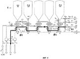
Фиг.2 показывает в перспективном изображении установленные в ряд три резервуара резервуарной станции, оснащенные предлагаемыми в изобретении устройствами в предпочтительном варианте.Figure 2 shows in a perspective image mounted in a row three tanks of the reservoir station, equipped with the devices of the invention in the preferred embodiment.
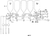
Фиг.3 показывает в схематическом изображении устройство по Фиг.2 с пятью резервуарами, жестко соединенными с четырьмя трубопроводами (функциональными линиями), причем клапаны на распределительных стойках представляют собой так называемые клапаны с двумя уплотнением.Figure 3 shows in a schematic illustration the device of Figure 2 with five tanks rigidly connected to four pipelines (functional lines), and the valves on the distribution racks are the so-called valves with two seals.
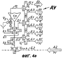
Фиг.4 показывает также в схематическом изображении устройство по Фиг.3, причем представлены примеры различных возможностей вытеснения.Figure 4 also shows in a schematic illustration the device of Figure 3, and presents examples of various extrusion possibilities.
Фиг.4а показывает в схематическом изображении и в виде выреза другое, отличающееся от изображенного на Фиг.4, клапанное устройство для вытеснения продукта из трубопроводов на участке последнего резервуара с такими же клапанами с двумя уплотнениями, что и на участке клапанных распределительных стоек.Fig. 4a shows in a schematic and cutaway another valve device, different from that shown in Fig. 4, for displacing a product from pipelines in a section of the last tank with the same valves with two seals as in a section of valve distribution racks.
Фиг.5 показывает в схематическом изображении другой вариант исполнения предлагаемого приспособления согласно Фиг.3, при котором установленные на клапанных распределительных стойках предохраняющие от смешивания клапаны представляют собой так называемые двухседельные клапаны первого рода.FIG. 5 shows in a schematic diagram another embodiment of the device according to FIG. 3, wherein the mixing protection valves installed on the valve distribution racks are the so-called two-seat valves of the first kind.
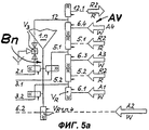
Фиг.5а показывает в схематическом изображении и в виде выреза другое, отличающееся от изображенного на Фиг.5, клапанное устройство для вытеснения продукта из трубопроводов на участке последнего резервуара с такими же двухседельными клапанами, что и на участке клапанных распределительных стоек.Fig. 5a shows, in a schematic representation and in the form of a cutaway, another valve device for displacing a product from pipelines in a section of the last tank with the same two-seat valves as in a section of valve distribution racks, different from that shown in Fig. 5.
Фиг.6 показывает меридиональное сечение через распределительную стойку, оснащенную двухседельными клапанами второго рода.6 shows a meridional section through a distribution strut equipped with two-seat valves of the second kind.
Раскрытие изобретенияDisclosure of invention
На Фиг.2 показан резервуарный парк 1, состоящий из трех резервуаров 1.1, 1.2 и 1.3, установленных в ряд. Днища 1.1а, 1.2а, 1.3а резервуаров 1.1, 1.2 и 1.3 заканчиваются в нижнем конце клапанными распределительными стойками В1, В2, В3, выполняемыми предпочтительно в виде вытянутых в длину полых корпусов В1а, В2а, В3а, имеющих форму цилиндрических трубок. Продольные оси полых корпусов В1а, В2а, В3а ориентированы вертикально и совпадают с продольными осями соответствующих резервуаров 1.1...1.3. К повернутым в противоположную сторону от днищ резервуаров 1.1а...1.3а нижним концам полых корпусов В1а...В3а присоединен трубопровод промывки 4, соединяющий подряд все полые корпуса В1а...В3а между собой. Первая группа трубопроводов, в которой трубопроводы 2.1, 2.2 и 2.3 расположены в ряд друг под другом в плоскости, параллельной плоскости продольных осей полых корпусов В1а...В3а, прокладывается как можно ближе к последним. Аналогичным образом вторая группа трубопроводов, состоящая из трубопроводов 3.1, 3.2 и 3.3, располагается относительно полых корпусов В1а...В3а, причем так, чтобы плоскость их расположения была параллельна плоскости расположения первой группы трубопроводов 2.1, 2.2, 2.3 и проходила с другой, противоположной стороны полых корпусов В1а...В3а. При этом все трубопроводы 2.1...3.3 проходят подряд мимо всех полых корпусов В1а...В3а и соединяются по выбору и с возможностью переключения предохраняющими от смешивания клапанами VC, VR, VR* или VS с внутренним пространством полых корпусов В1а...В3а.Figure 2 shows the
Предлагаемое в изобретении устройство разъясняется далее на Фиг.3 на пяти резервуарах, которые могут, например, использоваться в качестве ферментаторов. Здесь пятый резервуар, идущий после резервуаров 1.1...1.4, обозначен 1.n. Таким обобщенным обозначением указывается, что предлагаемое в изобретении устройство может распространяться на большее количество резервуаров. На каждой из клапанных распределительных стоек В1...Bn в приведенном примере установлено по четыре предохраняющих от смешивания клапана с двумя уплотнениями Vc (например, на резервуаре 1.1 это клапаны VC1.1.1, VC1.1.2, VC1.1.3, VC1.1.4), причем клапаны с двумя уплотнениями VC1.1.4...VC1.n.4, установленные на нижних концах клапанных распределительных стоек В1...Bn, соединяют трубопровод промывки 4 со всеми клапанными распределительными стойками В1...Bn. В трубопровод промывки 4 через второй трубопровод вытеснения 6.2 в ходе второго вытеснения А2 подается вытесняющая вода W, а на его другом конце находится второй насос 14, который удаляет моющий раствор R после промывки резервуара R1 или вытесняющую воду W после вытеснения А2. Через первый трубопровод заливки 2.1 в процессе первой заливки F1 может подаваться, например, сусло WZ в тот или иной резервуар 1.1, ..., 1.n. Для этой цели трубопровод 2.1 через один из клапанов с двумя уплотнениями VC1.1.2...VC1.n.2 подключается к выбранной клапанной распределительной стойке В1...Bn. Трубопровод 2.1 заканчивается в клапанном устройстве AV, предназначенном для вытеснения продукта из трубопроводов. Для этой цели трубопровод 2.1 сначала через запорный клапан V3 с тремя присоединениями к корпусу, а затем через двухседельные клапаны VD3 и VD2 и примыкающий спускной трубопровод промывки труб 12 выводится за пределы системы трубопроводов. Первое опорожнение Е1 осуществляется через первый трубопровод опорожнения 3.1. Это может быть, например, молодое пиво J, которое из одного из резервуаров 1.1, ..., 1.n через соответствующую клапанную распределительную стойку В1...Bn и соответствующий клапан VC1.1.3...VC1.n.3 с двумя уплотнениями поступает в трубопровод 3.1 и насосом 13 перекачивается в следующий цех. С другой стороны трубопровод 3.1 заканчивается тоже в клапанном устройстве AV для вытеснения продукта из трубопровода, причем в данном случае предусмотрен двухседельный клапан VD4, а за ним двухседельный клапан VD2 (не обозначен), к которому через первый подводящий трубопровод промывки труб 5.1 может быть подан моющий раствор R для промывки труб R2.Proposed in the invention, the device is explained further in Figure 3 on five tanks, which can, for example, be used as fermenters. Here the fifth tank, going after tanks 1.1 ... 1.4, is designated 1.n. Such a generic designation indicates that the device according to the invention can extend to more tanks. On each of the valve distribution racks B1 ... Bn in the above example, four valves preventing mixing with two Vc seals are installed (for example, on tank 1.1 these are valves V C1.1.1 , V C1.1.2 , V C1.1.3 , V C1 .1.4 ), and valves with two seals V C1.1.4 ... V C1.n.4 , mounted on the lower ends of the valve distribution racks B1 ... Bn, connect the
Аналогичным по смыслу образом функционирует второе опорожнение Е2. Здесь может иметь место, например, спуск дрожжей Н*. Для этого предусмотрен второй трубопровод опорожнения 3.2 с третьим насосом 16, который через выбранный клапан VC1.1.1...VC1.n.1 с двумя уплотнениями может быть подключен к соответствующей клапанной распределительной стойке В1...Bn. Трубопровод 3.2 с другого конца тоже заканчивается в клапанном устройстве AV; в данном случае он через двухседельные клапаны VD4 и VD2 соединяется со вторым подводящим трубопроводом промывки труб 5.2, в который при промывке труб R2 может быть подан моющий раствор R. Для вытеснения А1 трубопроводов 2.1, 3.1 и 3.2 предусмотрен первый трубопровод вытеснения 6.1, через который в систему трубопроводов может подаваться вытесняющая вода W.In a similar sense, the second emptying E2 functions. Here, for example, the descent of H * yeast can take place. For this, a second drainage pipeline 3.2 is provided with a
Предлагаемое в изобретении устройство, как оно представлено на фиг.2 и 3, дает немалую экономию места по сравнению с известными устройствами. Например, в пивоварении применяются цилиндроконические резервуары 1.1...1.n, которые обычно со своими днищами 1.1а...1.na проходят сквозь потолок или монтируются на помосте, так что предлагаемое в изобретении устройство без проблем может быть размещено под выпуском резервуара. Через проходящий у нижних концов клапанных распределительных стоек В1...Bn трубопровод промывки 4, действующий как выпускной трубопровод резервуаров, любой резервуар 1.1...1.n может быть без остатка опорожнен, включая его клапанную распределительную стойку В1...Bn. При заполненном резервуаре 1.1...1.n клапанная распределительная стойка В1...Bn практически представляет собой продолжение днища резервуара, в котором с одной стороны может происходить массообмен путем конвекции, а с другой стороны не будет происходить разогрева при промывке расположенных сбоку у клапанных распределительных стоек В1...Bn функциональных трубопроводов 2.1...3.3. Это препятствует образованию благоприятной для роста микроорганизмов среды в резервуарах 1.1...1.n. Кроме того, в случае ферментатора именно в нижней части днища резервуара 1.1а...1.na (в конусе резервуара) имеет место наибольшее скопление дрожжей, тормозящих развитие микроорганизмов.Proposed in the invention, the device, as it is shown in figure 2 and 3, gives considerable savings in space compared with known devices. For example, in brewing, cylinder-conical tanks 1.1 ... 1.n are used, which usually with their bottoms 1.1a ... 1.na pass through the ceiling or are mounted on a platform, so that the device proposed in the invention can easily be placed under the outlet of the tank . Through the
На Фиг.4 наглядно показано управление так называемым вытеснением. Если, например, нужно произвести вытеснение во втором трубопроводе опорожнения 3.2, по которому перед этим производился спуск дрожжей Н* из одного из резервуаров 1.1...1.n, то из трубопровода вытеснения 6.1 через двухседельный клапан VD4 подается вытесняющая вода W. Эта вода полностью вытесняет находящиеся в трубопроводе 3.2 дрожжи Н* через третий насос 16 к месту их назначения. Видно, что не остается никаких «мертвых концов труб», и потери продукта, если они вообще возможны, сводятся к минимуму.Figure 4 clearly shows the control of the so-called displacement. If, for example, it is necessary to displace in the second discharge pipeline 3.2, through which yeast Н * was drained from one of the tanks 1.1 ... 1.n before, then displacement water W. is supplied from the displacement pipeline 6.1 through the two-seat valve V D4 . water completely displaces the H * yeast located in the pipeline 3.2 through the
Если, например, в процессе заливки F1 требуется залить сусло WZ в резервуар 1.2 через первый трубопровод заливки 2.1, то для этого открывается клапан VC1.2.2 с двумя уплотнениями. Сусло WZ поступает в резервуар 1.2 и при этом заполняет также участок трубопровода 2.1, расположенный по направлению течения за клапаном VC1.2.2 с двумя уплотнениями. На этом участке можно по окончании заливки резервуара 1.2 произвести так называемое «обратное вытеснение» А1, которое начинается в клапанном устройстве AV с подачи вытесняющей воды W в первый трубопровод вытеснения 6.1. Запорный клапан 15 запирается, и находящееся в трубопроводе 2.1 сусло WZ почти полностью вытесняется в резервуар 1.2 через клапан VC1.2.2 с двумя уплотнениями.If, for example, during the pouring process F1, it is necessary to pour the wort WZ into the tank 1.2 through the first filling pipe 2.1, then valve V C1.2.2 with two seals opens for this. The wort WZ enters the reservoir 1.2 and also fills the section of the pipeline 2.1, located in the direction of flow behind the valve V C1.2.2 with two seals. In this section, after filling the reservoir 1.2, it is possible to produce the so-called “backward displacement” A1, which begins in the valve device AV with the supply of displacing water W to the first displacement pipeline 6.1. The shut-off
На Фиг.4А изображено клапанное устройство AV для вытеснения продукта из трубопроводов, в котором применены такие же клапаны с двумя уплотнениями VC, какие используются в клапанных распределительных стойках В1...Bn. Из схемы видно, что трубопроводы 2.1, 3.1 и 3.2 после своих клапанов с двумя уплотнениями VC либо заканчиваются на конечном участке спускного трубопровода промывки резервуаров 12.1 (трубопровод 2.1) или, соответственно, на первом и на втором подающих трубопроводах 5.1 и 5.2 промывки труб R2 для подачи или удаления моющего раствора R (трубопроводы 3.1 и 3.2), либо подключаются с целью вытеснения А4, A3, А1 с помощью вытесняющей воды W к четвертому, третьему или первому трубопроводу вытеснения 6.4, 6.3 или 6.1.4A illustrates the valve AV device to displace the product from the pipeline, in which applied the same valve with two seals V C, which are used in the valve B1 ... Bn distribution racks. It can be seen from the diagram that pipelines 2.1, 3.1, and 3.2, after their valves with two seals V C, either end at the end of the drain pipe for washing tanks 12.1 (pipe 2.1) or, respectively, at the first and second supply pipes 5.1 and 5.2 for washing pipes R2 to supply or remove the cleaning solution R (pipelines 3.1 and 3.2), or are connected to displace A4, A3, A1 with the help of displacing water W to the fourth, third or first displacement pipelines 6.4, 6.3 or 6.1.
Фиг.5 поясняет вариант предложенного в изобретении устройства, в котором вместо показанных на Фиг.4 клапанов с двумя уплотнениями применены так называемые двухседельные клапаны первого типа VR или второго типа VR*. В схеме используются обозначения только двухседельных клапанов первого типа VR. Ни различие этих двух форм исполнения VR и VR* между собой, ни различие между этими двумя формами с одной стороны и клапаном с двумя уплотнениями VC с другой стороны не влияют на принципиальное построение предложенного в изобретении устройства. Разница состоит разве что в большей степени надежности, которой предохраняющие от смешивания клапаны VR и VR* отличаются от клапана с двумя уплотнениями VC. Кроме того, полость утечки в двухседельных клапанах VR и VR* можно очищать не только при закрытом, но и при открытом положении клапана.FIG. 5 illustrates an embodiment of the device of the invention in which instead of the valves with two seals shown in FIG. 4, so-called two-seat valves of the first type V R or the second type V R * are used . The designation uses only the designations of the two-seat valves of the first type V R. Neither the difference between the two forms of execution of V R and V R * between themselves, nor the difference between the two forms on the one hand and the valve with two seals V C on the other hand affects the fundamental construction of the device proposed in the invention. The only difference is, to a greater degree of reliability, that the mixing valves V R and V R * are different from the valve with two V C seals. In addition, the leakage cavity in the two-seat valves V R and V R * can be cleaned not only with the valve closed, but also with the valve open.
Из Фиг.5а видно, что и клапанное устройство AV для вытеснения продукта из трубопроводов тоже может быть полностью построено на вышеописанных двухседельных клапанах первого рода VR, прототип которых известен, например, из US-PS 4436106 или второго рода VR*, прототип которых описан, например, в DE-C-3701027.Figure 5a shows that the valve device AV for displacing the product from pipelines can also be completely built on the above-described two-seat valves of the first kind V R , the prototype of which is known, for example, from US-PS 4436106 or the second kind of V R * , the prototype of which described, for example, in DE-C-3701027.
Пример конкретного исполнения распределительной стойки В1...Bn с двухседельными клапанами второго рода VR* (DE-C-3701027) показан на Фиг.6. Вытянутый в длину полый корпус В1а...Bna присоединен к выпускному отверстию 24 днища резервуара 1.1а...1.na и направлен вертикально вниз. Полый корпус В1а...Bna через патрубки 17 соединяется с трубопроводами 2.1...2.3 и 3.1...3.3, а его нижний конец соединен с трубопроводом 4. На каждом из патрубков 17 установлен двухседельный клапан второго рода VR*, в котором имеется замыкающий элемент 18, выполненный в виде задвижки, и запорная деталь с внутренним проходом 19, выполненная также в виде задвижки. Со стороны корпуса клапана расположены на расстоянии друг от друга места уплотнения 20 и 21, которые при запертом положении двухседельного клапана, показанном на чертеже, взаимодействуют с замыкающим элементом 18, а при открытом положении двухседельного клапана - с запорной деталью с внутренним проходом 19. Образованная со стороны корпуса клапана полость утечки 22 между местами уплотнения 20 и 21 соединена каналом 23 для отвода протекшей жидкости в пространство, окружающее клапан. Из чертежа видно, что конструкция двухседельного клапана VR* позволяет без проблем обеспечить при закрытом положении клапана запирание внутренней полости полого корпуса В1а...Bna обращенной к ней торцовой поверхностью замыкающего элемента 18 почти заподлицо в соответствии с идеей изобретения.An example of a specific design of the distribution rack B1 ... Bn with two-seat valves of the second kind V R * (DE-C-3701027) is shown in Fig.6. The elongated hollow body B1a ... Bna is connected to the
Список условных обозначенийLegend List
Фиг.1 (Известное из уровня техники устройство)Figure 1 (Known from the prior art device)
Фиг.2-6 (дополнительные обозначения к обозначениям Фиг.1)Figure 2-6 (additional notation to the notation of Figure 1)
Claims (16)
Applications Claiming Priority (2)
| Application Number | Priority Date | Filing Date | Title |
|---|---|---|---|
| DE10108259A DE10108259C1 (en) | 2001-02-21 | 2001-02-21 | Storage tank system for use in food and drink, pharmaceutical and biotechnology industries, comprises pipes connected to distributor trees attached to tank bases and fitted with valves for control of liquid flow |
| DE10108259.2 | 2001-02-21 |
Publications (2)
| Publication Number | Publication Date |
|---|---|
| RU2003128974A RU2003128974A (en) | 2005-05-10 |
| RU2273600C2 true RU2273600C2 (en) | 2006-04-10 |
Family
ID=7674945
Family Applications (1)
| Application Number | Title | Priority Date | Filing Date |
|---|---|---|---|
| RU2003128974/12A RU2273600C2 (en) | 2001-02-21 | 2002-01-17 | Method and the device for exploitation of the tanks stations |
Country Status (10)
| Country | Link |
|---|---|
| US (1) | US7302958B2 (en) |
| EP (1) | EP1363990B1 (en) |
| JP (1) | JP4142442B2 (en) |
| AT (1) | ATE364074T1 (en) |
| DE (2) | DE10108259C1 (en) |
| DK (1) | DK1363990T3 (en) |
| ES (1) | ES2287244T3 (en) |
| PL (1) | PL200870B1 (en) |
| RU (1) | RU2273600C2 (en) |
| WO (1) | WO2002066593A1 (en) |
Cited By (1)
| Publication number | Priority date | Publication date | Assignee | Title |
|---|---|---|---|---|
| RU2509050C2 (en) * | 2009-05-12 | 2014-03-10 | Кронэс Аг | System of pipelines |
Families Citing this family (21)
| Publication number | Priority date | Publication date | Assignee | Title |
|---|---|---|---|---|
| DE10345699B3 (en) * | 2003-10-01 | 2005-04-28 | Tuchenhagen Gmbh | Distributor device for valves |
| US7338595B2 (en) * | 2003-11-13 | 2008-03-04 | Culligan International Company | Flow-through tank for water treatment |
| DE102004006889B3 (en) * | 2004-02-12 | 2005-08-11 | Tuchenhagen Gmbh | Distribution device for valves has housing in two parts, each with channel recess complementary to cavity |
| DE102004022567B4 (en) * | 2004-05-07 | 2006-05-24 | Tuchenhagen Gmbh | Method and arrangement for operating tank storage systems in the solid-lined composite with pipe systems for liquids |
| DE102005051467A1 (en) | 2005-10-24 | 2007-04-26 | Südmo Holding GmbH | Manifold arrangement |
| DE102007011094B4 (en) * | 2007-02-28 | 2010-08-19 | Südmo Holding GmbH | Steam sterilizer unit for creating a vapor barrier in a leakage chamber |
| DE102007011084B4 (en) * | 2007-02-28 | 2013-11-28 | Südmo Holding GmbH | Valve device for a plant for product management, such a plant and a method for operating the same |
| DE102007020183B3 (en) * | 2007-04-28 | 2008-09-04 | Tuchenhagen Gmbh | Device for operating a petrol storage system comprises pipelines formed in the region of a valve distribution tree in the form of a equalizing arc partly enclosed with its sides in a plane perpendicular to a longitudinal axis of the tree |
| DE102008051819A1 (en) | 2008-07-31 | 2010-02-25 | Gea Tuchenhagen Gmbh | Apparatus for piping process plants in the food and beverage industry and method for operating a device |
| DE102008026149A1 (en) | 2008-05-30 | 2009-12-03 | Gea Tuchenhagen Gmbh | Piping system for use in food- and beverage industries, has cylindrical receiving borehole formed with cylindrical seat surface, where borehole and seat surface are merged with each other in closed position in aligned manner |
| EP2434186A1 (en) | 2008-05-30 | 2012-03-28 | GEA Tuchenhagen GmbH | Device for installing piping in process plants in the food and beverage industry |
| DE202008012022U1 (en) | 2008-09-10 | 2008-12-24 | Tuchenhagen Brewery Systems Gmbh | tank system |
| DE102009032547A1 (en) * | 2009-07-10 | 2011-01-13 | Krones Ag | Method for the automated control of a pipeline network |
| DE102009055742A1 (en) * | 2009-09-04 | 2011-04-07 | Gea Brewery Systems Gmbh | Device for operating storage tank system that is connected with fluid pipe system in e.g. food and beverage industry, has valves forming valve block in crossing area of pipelines that run in vertical planes arranged parallel to each other |
| WO2013113793A1 (en) | 2012-02-03 | 2013-08-08 | Tetra Laval Holdings & Finance S.A. | A liquid processing system with secondary sub-systems for reducing product losses and water consumption |
| US9644795B2 (en) * | 2012-12-18 | 2017-05-09 | Baker Hughes Incorporated | Fracturing fluid process plant and method thereof |
| DE102013214729A1 (en) * | 2013-07-29 | 2015-01-29 | Krones Ag | tank connection |
| CN104291038A (en) * | 2014-09-25 | 2015-01-21 | 成都市花香酒业有限公司 | Wine tank with combined conveying tube |
| US9546897B1 (en) * | 2015-01-06 | 2017-01-17 | Kenco International, Inc. | Modular and reversible manifold assembly for a pump settling gauge |
| USD885821S1 (en) * | 2018-09-03 | 2020-06-02 | Unibio A/S | Fermenter for manufacture of proteins |
| CN111536274A (en) * | 2020-05-06 | 2020-08-14 | 北京美联泰科生物技术有限公司 | Multi-liquid-path selector valve and integrated multi-channel liquid path module |
Family Cites Families (12)
| Publication number | Priority date | Publication date | Assignee | Title |
|---|---|---|---|---|
| US3120326A (en) * | 1960-08-26 | 1964-02-04 | Robert M Hedeman | Beverage dispenser conduit purging device |
| DE2229978A1 (en) * | 1972-06-20 | 1974-01-10 | Ahlborn E Ag | ROTARY FLAP VALVE |
| US4074687A (en) * | 1976-06-30 | 1978-02-21 | Joyce John E | Method of and apparatus for use in generating liquid concentration gradients hydrostatically |
| SE437710B (en) * | 1977-01-29 | 1985-03-11 | Tuchenhagen Otto Gmbh | PIPE CONNECTORS WITH LEAK CONTROL AND CLEANABLE LECK CHAMBER AND EXPORTED AS DOUBLE-SET COUPLING FOR PIPE PIPES |
| DE7702634U1 (en) * | 1977-01-29 | 1979-02-15 | Fa. Otto Tuchenhagen, 2059 Buechen | PIPELINE SWITCH WITH LEAK CONTROL AND CLEANABLE LEAKAGE CAVITY |
| GB2077759B (en) | 1980-05-23 | 1984-02-01 | Ward John Robert Jnr | Brewing alcoholic beverages and apparatus therefor |
| US4710355A (en) * | 1984-06-14 | 1987-12-01 | Olympus Optical Co., Ltd. | Reagent delivery device |
| DE3516128A1 (en) * | 1985-05-04 | 1986-11-06 | Gea Ahlborn Gmbh & Co Kg, 3203 Sarstedt | Double seat valve |
| FR2582637B1 (en) * | 1985-06-03 | 1987-12-04 | Inst Fs Boissons Brasserie M | DEVICE AND METHOD FOR CONNECTING TANKS, ESPECIALLY BREWERY TANKS |
| DE3701027A1 (en) * | 1987-01-16 | 1988-07-28 | Hans Otto Mieth | METHOD AND DEVICE FOR CONTROLLING A LEAKAGE SPACE OF A VALVE |
| US6314978B1 (en) * | 1996-02-21 | 2001-11-13 | Mcdonnell Douglas Corporation | Reciprocating feed system for fluids |
| DE29821813U1 (en) * | 1998-12-07 | 1999-02-04 | Steinecker Maschf Anton | Switch panel |
-
2001
- 2001-02-21 DE DE10108259A patent/DE10108259C1/en not_active Ceased
-
2002
- 2002-01-17 AT AT02702276T patent/ATE364074T1/en not_active IP Right Cessation
- 2002-01-17 WO PCT/EP2002/000432 patent/WO2002066593A1/en active IP Right Grant
- 2002-01-17 ES ES02702276T patent/ES2287244T3/en not_active Expired - Lifetime
- 2002-01-17 EP EP02702276A patent/EP1363990B1/en not_active Expired - Lifetime
- 2002-01-17 DK DK02702276T patent/DK1363990T3/en active
- 2002-01-17 RU RU2003128974/12A patent/RU2273600C2/en active
- 2002-01-17 DE DE50210272T patent/DE50210272D1/en not_active Expired - Lifetime
- 2002-01-17 JP JP2002566300A patent/JP4142442B2/en not_active Expired - Fee Related
- 2002-01-17 PL PL363304A patent/PL200870B1/en unknown
- 2002-01-17 US US10/467,757 patent/US7302958B2/en active Active
Cited By (1)
| Publication number | Priority date | Publication date | Assignee | Title |
|---|---|---|---|---|
| RU2509050C2 (en) * | 2009-05-12 | 2014-03-10 | Кронэс Аг | System of pipelines |
Also Published As
| Publication number | Publication date |
|---|---|
| PL200870B1 (en) | 2009-02-27 |
| RU2003128974A (en) | 2005-05-10 |
| EP1363990A1 (en) | 2003-11-26 |
| ATE364074T1 (en) | 2007-06-15 |
| DE10108259C1 (en) | 2002-01-03 |
| JP2004532621A (en) | 2004-10-28 |
| DE50210272D1 (en) | 2007-07-19 |
| PL363304A1 (en) | 2004-11-15 |
| DK1363990T3 (en) | 2007-10-08 |
| US20040123902A1 (en) | 2004-07-01 |
| JP4142442B2 (en) | 2008-09-03 |
| ES2287244T3 (en) | 2007-12-16 |
| WO2002066593A1 (en) | 2002-08-29 |
| US7302958B2 (en) | 2007-12-04 |
| EP1363990B1 (en) | 2007-06-06 |
Similar Documents
| Publication | Publication Date | Title |
|---|---|---|
| RU2273600C2 (en) | Method and the device for exploitation of the tanks stations | |
| US5469880A (en) | Manifold valve assemblies with cleaning solution supply | |
| US5232023A (en) | Manifold valve assemblies | |
| EP1188973B1 (en) | Double seat valve | |
| CN102458699A (en) | Piping system | |
| KR101330391B1 (en) | Pipe branching arrangement | |
| CA2726068C (en) | Piping system for process plants in the food and beverage industry | |
| US8714185B2 (en) | Device for the piping of process systems in the food and beverage industry | |
| US5441079A (en) | Manifold valve assemblies | |
| RU2421508C1 (en) | Device for operation of reserve storage systems with rigid piping with systems of pipes for fluid mediums | |
| CN204756881U (en) | Low hydrophobic flash vessel of hush steam | |
| CN205762754U (en) | For water tank assembly for irrigating needle online cleaning and sterilizing | |
| CN109695824B (en) | Valve array structure and pharmaceutical system applying same | |
| CN206598397U (en) | Concrete additive feeding device | |
| CN206298582U (en) | A kind of liquid mixing system of continuous liquid supply | |
| CN106081393B (en) | A kind of the multifunctional pipe connection and valve control structure of hold-up vessel | |
| US20160369215A1 (en) | Tank Connection | |
| CN209205957U (en) | Pipeline chemical cleaning vehicle | |
| CN210912975U (en) | Alternating medicine gel preparation system | |
| CN206958605U (en) | A kind of anti-mixing control device of Beverage Service pipeline | |
| CN205350500U (en) | Two type PE ball valves that diffuse | |
| Ratz | Dale A. Seiberling | |
| JP2000185248A (en) | Method and apparatus for switching raw material which is separated easily | |
| CZ18558U1 (en) | Distributing valve for discharge of single chamber washing apparatus |
Legal Events
| Date | Code | Title | Description |
|---|---|---|---|
| PD4A | Correction of name of patent owner | ||
| PC4A | Invention patent assignment |
Effective date: 20100726 |