EP2434186A1 - Device for installing piping in process plants in the food and beverage industry - Google Patents
Device for installing piping in process plants in the food and beverage industry Download PDFInfo
- Publication number
- EP2434186A1 EP2434186A1 EP20110008568 EP11008568A EP2434186A1 EP 2434186 A1 EP2434186 A1 EP 2434186A1 EP 20110008568 EP20110008568 EP 20110008568 EP 11008568 A EP11008568 A EP 11008568A EP 2434186 A1 EP2434186 A1 EP 2434186A1
- Authority
- EP
- European Patent Office
- Prior art keywords
- valve
- pipe
- connection
- hollow structure
- housing
- Prior art date
- Legal status (The legal status is an assumption and is not a legal conclusion. Google has not performed a legal analysis and makes no representation as to the accuracy of the status listed.)
- Withdrawn
Links
Images


Classifications
-
- F—MECHANICAL ENGINEERING; LIGHTING; HEATING; WEAPONS; BLASTING
- F16—ENGINEERING ELEMENTS AND UNITS; GENERAL MEASURES FOR PRODUCING AND MAINTAINING EFFECTIVE FUNCTIONING OF MACHINES OR INSTALLATIONS; THERMAL INSULATION IN GENERAL
- F16K—VALVES; TAPS; COCKS; ACTUATING-FLOATS; DEVICES FOR VENTING OR AERATING
- F16K1/00—Lift valves or globe valves, i.e. cut-off apparatus with closure members having at least a component of their opening and closing motion perpendicular to the closing faces
- F16K1/32—Details
- F16K1/34—Cutting-off parts, e.g. valve members, seats
- F16K1/44—Details of seats or valve members of double-seat valves
- F16K1/443—Details of seats or valve members of double-seat valves the seats being in series
- F16K1/446—Details of seats or valve members of double-seat valves the seats being in series with additional cleaning or venting means between the two seats
-
- B—PERFORMING OPERATIONS; TRANSPORTING
- B67—OPENING, CLOSING OR CLEANING BOTTLES, JARS OR SIMILAR CONTAINERS; LIQUID HANDLING
- B67D—DISPENSING, DELIVERING OR TRANSFERRING LIQUIDS, NOT OTHERWISE PROVIDED FOR
- B67D7/00—Apparatus or devices for transferring liquids from bulk storage containers or reservoirs into vehicles or into portable containers, e.g. for retail sale purposes
- B67D7/06—Details or accessories
- B67D7/36—Arrangements of flow- or pressure-control valves
-
- B—PERFORMING OPERATIONS; TRANSPORTING
- B67—OPENING, CLOSING OR CLEANING BOTTLES, JARS OR SIMILAR CONTAINERS; LIQUID HANDLING
- B67D—DISPENSING, DELIVERING OR TRANSFERRING LIQUIDS, NOT OTHERWISE PROVIDED FOR
- B67D7/00—Apparatus or devices for transferring liquids from bulk storage containers or reservoirs into vehicles or into portable containers, e.g. for retail sale purposes
- B67D7/06—Details or accessories
- B67D7/78—Arrangements of storage tanks, reservoirs or pipe-lines
-
- B—PERFORMING OPERATIONS; TRANSPORTING
- B67—OPENING, CLOSING OR CLEANING BOTTLES, JARS OR SIMILAR CONTAINERS; LIQUID HANDLING
- B67D—DISPENSING, DELIVERING OR TRANSFERRING LIQUIDS, NOT OTHERWISE PROVIDED FOR
- B67D2210/00—Indexing scheme relating to aspects and details of apparatus or devices for dispensing beverages on draught or for controlling flow of liquids under gravity from storage containers for dispensing purposes
- B67D2210/00028—Constructional details
- B67D2210/00047—Piping
- B67D2210/0006—Manifolds
-
- Y—GENERAL TAGGING OF NEW TECHNOLOGICAL DEVELOPMENTS; GENERAL TAGGING OF CROSS-SECTIONAL TECHNOLOGIES SPANNING OVER SEVERAL SECTIONS OF THE IPC; TECHNICAL SUBJECTS COVERED BY FORMER USPC CROSS-REFERENCE ART COLLECTIONS [XRACs] AND DIGESTS
- Y10—TECHNICAL SUBJECTS COVERED BY FORMER USPC
- Y10T—TECHNICAL SUBJECTS COVERED BY FORMER US CLASSIFICATION
- Y10T137/00—Fluid handling
- Y10T137/4238—With cleaner, lubrication added to fluid or liquid sealing at valve interface
- Y10T137/4245—Cleaning or steam sterilizing
- Y10T137/4259—With separate material addition
-
- Y—GENERAL TAGGING OF NEW TECHNOLOGICAL DEVELOPMENTS; GENERAL TAGGING OF CROSS-SECTIONAL TECHNOLOGIES SPANNING OVER SEVERAL SECTIONS OF THE IPC; TECHNICAL SUBJECTS COVERED BY FORMER USPC CROSS-REFERENCE ART COLLECTIONS [XRACs] AND DIGESTS
- Y10—TECHNICAL SUBJECTS COVERED BY FORMER USPC
- Y10T—TECHNICAL SUBJECTS COVERED BY FORMER US CLASSIFICATION
- Y10T137/00—Fluid handling
- Y10T137/8593—Systems
- Y10T137/87249—Multiple inlet with multiple outlet
-
- Y—GENERAL TAGGING OF NEW TECHNOLOGICAL DEVELOPMENTS; GENERAL TAGGING OF CROSS-SECTIONAL TECHNOLOGIES SPANNING OVER SEVERAL SECTIONS OF THE IPC; TECHNICAL SUBJECTS COVERED BY FORMER USPC CROSS-REFERENCE ART COLLECTIONS [XRACs] AND DIGESTS
- Y10—TECHNICAL SUBJECTS COVERED BY FORMER USPC
- Y10T—TECHNICAL SUBJECTS COVERED BY FORMER US CLASSIFICATION
- Y10T137/00—Fluid handling
- Y10T137/8593—Systems
- Y10T137/877—With flow control means for branched passages
-
- Y—GENERAL TAGGING OF NEW TECHNOLOGICAL DEVELOPMENTS; GENERAL TAGGING OF CROSS-SECTIONAL TECHNOLOGIES SPANNING OVER SEVERAL SECTIONS OF THE IPC; TECHNICAL SUBJECTS COVERED BY FORMER USPC CROSS-REFERENCE ART COLLECTIONS [XRACs] AND DIGESTS
- Y10—TECHNICAL SUBJECTS COVERED BY FORMER USPC
- Y10T—TECHNICAL SUBJECTS COVERED BY FORMER US CLASSIFICATION
- Y10T137/00—Fluid handling
- Y10T137/8593—Systems
- Y10T137/87917—Flow path with serial valves and/or closures
- Y10T137/88022—One valve head provides seat for other head
- Y10T137/8803—Also carries head of other valve
Definitions
- the invention relates to a device for piping of process equipment of the food and beverage industry according to the preamble of claim 1, wherein these devices are particularly applicable where the product handling and product transfer process facilities serving high microbiological quality requirements and demands for best cleaning ability in the flow (so-called CIP capability) and where a compact and flexible design of the plant is required.
- CIP capability the product handling and product transfer process facilities serving high microbiological quality requirements and demands for best cleaning ability in the flow
- the application also includes areas of pharmacy and biotechnology in particular.
- FIG. 1 of the document DE 101 08 259 C1 shown and described (Sections 003 to 020).
- This example describes a piping system of a brewery, which consists of five fermentation tanks. Their number is readily expandable and the plant may typically additionally include process units connected to the piping system.
- the supply lines from the various tanks and process units are fed to a valve block (referred to as VB) and distributed from there, for example, to associated filling machines and connected.
- VB valve block
- the connection points at which incompatible media can face each other are equipped with so-called mix-proof valves, typically double-seated valves.
- valve block can be made compact, even in process plants, where the tanks and process units are arbitrarily positioned. In addition to reduced costs and reduced space requirements, this simplifies the cleaning, maintenance and monitoring of the process plant.
- Another piping system is for example from the DE 101 08 259 C1
- this is limited to a piping arrangement in which a so-called valve manifold tree is associated with a tank of a tank storage system, directly from the tank bottom opens and a rising from bottom to top, usually has a vertical course.
- the process lines and function valves are mounted directly under the respective tank outlet.
- This piping system has been proven in practice in the meantime; it is in the company publication Tuchenhagen Brewery Systems, ECO-Matrix ®, 223d-10/06, described in more detail under the name ECO-Matrix ®, and in particular under the aspect of cost and the influence on the product quality.
- the function valves can either be attached to the side of the tank outlet tree, the so-called. Ventilverteilerbaum, or perpendicular to the bottom flange of the tank.
- This piping technique significantly minimizes the formation of contamination and its subsequent distribution in the process system.
- the piping system, separated from the tank, allows for complete product evacuation and tank-independent cleaning.
- the instrumentation costs are reduced in this newer piping technique, while the process for a nearly lossless production operation can be optimized.
- the valve manifold is designed as an elongated hollow body, it is oriented substantially vertically and it has connection openings for connection its interior with piping of a pipe system, which are guided laterally on the valve manifold.
- a mixing-resistant valve configured in its seating area is arranged, which switches this connection in the immediate vicinity of the hollow body.
- a so-called double-seat valve with two closing elements movable relative to one another or a so-called double-sealing valve with two seat seals spaced apart on a single closing element in the stroke direction or a so-called leak-proof disk valve can be used as a mix-proof valve.
- a leakage cavity connected to the vicinity of the double seat valve via at least one communication path.
- Double-seat valve As a preferred mix-safe valve found in the piping systems in question so far the vorg. Double-seat valve use, the latter having concentrically arranged one another valve rods for the closing members, which are on one side through the valve housing and led out of this to a drive.
- a double seat valve with a related Sch thoroughlyglied- and valve rod configuration is already out of the US 4 436 106 A known.
- the arranged between the two closing elements leakage cavity is drained via a leakage drain between the valve rod of the independently driven first closing member and a valve rod surrounding the hollow rod of the dependent driven second closing member.
- the second closing member is designed as a seat plate in the form of a conical closing sleeve which carries at its end facing the first closing member an axial seat seal, which cooperates with a valve seat on the valve housing.
- the first closure member is also formed as a seat plate, which cooperates with a conical valve seat.
- One in the DE 10 2005 051 467 A1 described piping arrangement is based on a piping according to DE 101 08 259 C1 in this system at the terminals of the hollow body in each case a mix-safe valve, wherein the first closing member is driven independently and comes at its opening movement formed as a seat plate second closing member sealingly to the plant and this also transferred to the open position.
- the second closing member has, at its end facing the first closing member, a second seat seal, which cooperates with a second seating face adjoining a cylindrical first seating face.
- the first closing element designed as a slide piston has a radially acting first seat seal which sealingly engages in the first seating surface in the closed position of the valve.
- the valve rods for the closing elements are arranged concentrically with one another and are guided on one side through the valve housing and out of this.
- the valve is the DE 10 2005 051 467 A1 arranged in an oblique arrangement on the hollow body and it has, in addition to the radial sealing means on the first closing member and the axial sealing means on the second closing member, a so-called. Center seal, which is arranged in the open position of the double seat valve between the two closing members and effective on the second closing member.
- the leakage cavity of the valve has a circumferential wall extending from a connection-side inlet to an outlet-side leakage outlet opening spaced from the inlet, which has a gradient on the gravity side toward the leakage outlet opening.
- the purpose of this measure is an automatic emptying of the leakage cavity of accumulating there leakage liquid.
- the known manifold arrangement according to the DE 10 2005 051 467 A1 is, as well as the piping system after the DE 101 08 259 C1 , Limited to an arrangement in which an upper end of the hollow body (valve manifold) opens directly or via another valve in a tank bottom of a tank disposed above.
- the object of the invention is to provide a device for piping the gattungsgemä- ⁇ en type, which meets high demands on the quality of the treated fluid product in high reliability, the total, including the mix-safe valves, simple, flexible and inexpensive is constructed and in all occurring in practice arrangement variants of the valve manifold tree in relation to the associated process unit or tank of the process plant in each valve manifold tree largely the same technological conditions and state variables as in the process unit or tank maps.
- the essence of the invention consists in that the fluid products to be supplied or discharged from the pipe system flow through the hollow structures delimited by the valve manifold on the way via connection openings and that the respective fluid in this hollow structure is in close proximity to its boundary from the associated (n) connection opening (s) zoom in and on the hollow structure passing piping of the pipe system by a mix-safe valve optional, switchable and mix safe separation.
- the respective valve manifold opens directly into the lower tank bottom of a respectively assigned tank of the process plant (first arrangement variant) or / and the respective valve manifold is connected via an associated pipe connection with an associated process unit or tank of the process plant and the pipe connection opens into the tank or process unit side End of the valve manifold tree (second arrangement variant). This makes the piping systems for the most diverse applications extremely easy.
- An advantageous embodiment provides that in the first directional variant, in which the valve manifold tree ascends from bottom to top, usually a vertical course, the first and the second group of pipes in each row-like arrangement with each other, on opposite sides of the hollow structure , in each other and to the longitudinal axis of the hollow structure are arranged in parallel planes.
- Such piping is extremely compact, space-saving and clear.
- the hollow structure allows a very simple connection of the mix-proof valve, if it is formed in the peripheral area of its connection opening as an annular housing which receives the two seats and serves to connect the valve housing.
- the execution of the hollow structure is particularly simple if it, as is still provided, is designed as a cylindrical tube.
- the hollow structure can be completely emptied and cleaned properly, if its the lower end remote from the respective tank or the respective pipe connection brought from the process unit or tank is connected to a third pipe system.
- the device becomes particularly clear and simple if, according to a further proposal, the pipelines are each designed as continuous pipelines (filling, emptying, pipe cleaning) assigned to all pipe connections in the same function.
- Simple and clear pipe guides arise in the context of the piping system, if the valve manifolds have a series or matrix-shaped arrangement.
- the hollow structure is composed in each case of an aggregation of individual structural sections which are fluidly interconnected in the direction of the longitudinal axis of the hollow structure and each have at least one connection opening.
- These housing parts may be either discrete, separate parts that are joined to the hollow structure in its entirety, or a one-piece, in which the individual housing parts are materially interconnected.
- Embodiments are, according to another proposal, the sections of the building in the form of housing parts of different sizes, so that at these housing parts, if necessary, as is also provided, at least one connection opening can be performed, which is dependent on the size of the respective associated housing part passage cross-section having. Connection openings with different sized passage cross sections on a housing part are also provided. Due to this design variety, the hollow structure in all its areas through which it flows can be adapted to the fluidic requirements of the connected pipelines of different nominal widths.
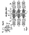
- a device 1 for piping process plants consists, for example, of three valve manifolds B1, B2 and B3, in the most general case of B1 to Bn valve manifolds, which are preferably arranged in rows and in alignment with each other.
- Each valve manifold tree B1, B2, B3 (Bi) is in the form of an elongate hollow structure B1a, B2a, B3a (in the most general case B1a to Bna; Bia), preferably in the form of a cylindrical tube or an aggregation of individual structural sections 5 (see FIG. FIG. 2 ) executed, which has a rising from bottom to top, usually a vertical course (first direction variant).
- the illustrated device 1 further shows a first pipe system 2, which consists of a first group of pipes 2.1, 2.2, 2.3 (in the most general case from 2.1 to 2.i to 2.n pipes), and a second pipe system 3, which consists of a second Group pipelines 3.1, 3.2, 3.3 (in the most general case from 3.1 to 3.i to 3.n piping) consists.
- a third pipe system 4 (for example, for cleaning) may be connected, if this place or access should not be available for other precautions.
- the first group of pipes 2.1, 2.2, 2.3 and the second group of pipes 3.1, 3.2, 3.3 are each arranged in a row with each other and, with respect to the front two Ventilverteilerbäume B1 and B2, on opposite sides of the hollow structure B1a, B2a, in two parallel to each other and to the longitudinal axis of the hollow structure arranged parallel planes and past this (two-sided arrangement of mix safe double seat valves V R ).
- the third hollow structure B3a is located, for example, directly in front of a vertical wall, so that only the first pipe system 2 is to be guided past it and to be connected (one-sided arrangement of the mix-proof double-seat valves V R ).
- FIG. 7 A perspective view of the rear valve manifold tree B3 substantially corresponding arrangement shows FIG. 7 .
- the hollow structure B1a, B2a, B3a has connection openings 6a (FIG. Figures 2 and 2a ) for connecting its interior to each of the pipes 2.1, 2.2, ..., 2.i, ..., 2.n and 3.1, 3.2, ..., 3.1, ..., 3.n and possibly 4
- the double-seated valve V R designed to be mixproof is arranged, which switches this connection in the immediate vicinity of the hollow structure B1 a, B2a, B3a.
- the respective valve manifold B1 to B3 (in the most general case B1 to Bi to Bn) opens either directly in the lower tank bottom T1a to T3a (in the most general case T1a to Tia to Tna) of a respectively assigned tank T1 to T3 (tank T;
- the most common case is T1 to Ti to Tn) of the process plant (first arrangement variant) or it is connected via an associated pipe connection R (R1 to R3, in the most general case R1 to Ri to Rn) with an associated process unit P (P1, P2, in the most general case P1 to Pi to Pn) or tank T1 (tank T, in the most general case T1 to Ti to Tn) of the process plant and the pipe joint R (R1 to R3 (in the most general case R1 to Ri to Rn) opens into the upper end of the valve manifold B1 to B3 (B1 to Bi to Bn) (second arrangement variant)
- the two aforementioned basic arrangement variants can also occur in a single device 1 (mix
- the upper end of the first valve manifold B1 is connected to a first process unit P1 via a first pipe connection R1
- the second valve manifold B2 is connected to a first tank T1 via a second pipe connection R2
- the third valve manifold B3 is connected via a third pipe connection R3 connected to a second process unit P2.
- the process units P or the tanks T can assume any arrangement and positioning in the second arrangement variant, while the valve manifolds B1 to Bn are preferably arranged in rows or in a matrix.
- the illustrated pipe joint R1 to R3 may be in the region of their connected to the valve manifold tree B1 to B3 (B1 to Bn) end portion in each case a vertical or any inclined end portion.
- the inclined end portion which extends horizontally in the limiting case, with a corresponding pipe bend connection to the tank or process unit end of the respective valve manifold tree B1 to B3 (B1 to Bn).
- valve manifolds Bi can, as will be explained in detail later, also be arranged horizontally (second direction variant).
- first direction variant For the connection of the respective horizontally arranged valve manifold tree Bi with the associated tank Ti or process unit Pi, the above statements apply mutatis mutandis.
- FIG. 2 shows that the hollow structure B1a, B2a (in the most general case Bia) can be composed, for example, of three identical structural sections 5, wherein each structural section 5 (FIG. FIG. 2a ) is formed in the peripheral region of its connection openings 6a as an annular housing 6, each receiving on the inside a first seat 6b, a second seat 6c and a cylindrical recess 6d.
- the annular housing 6 is adjoined, in each case transversely to the longitudinal direction (longitudinal axis L) of the structural section 5, on both sides by a first valve housing 7 (see also FIG FIG.
- the valve housing 7 is part of the mixproof double-seat valve V R. Connected to the valve housing 7, seen in the longitudinal direction of the double-sighted valve V R , laterally a leakage and drain housing 8 ( Figures 3 . 2 ) with a drain connection 8a and a non-descript drive, the latter being connected to the leakage and drain housing 8 via a lantern housing 9.
- the double seat valve V R is formed with two serially arranged closing members 10, 11, which in the closed position of the valve prevent the overflow of fluids from the hollow structure Bia or from the building section 5 into the valve housing 7.
- the closure members 10, 11 define both in the closed and in the open position a leakage cavity 14, the at least one connection path having the environment of the double seat valve V R.
- the interior of the leakage and drain housing 8 and its drain port 8a are part of this connection path.
- the first closing member 10 is connected to a first valve rod 10a and the second closing member 11 is connected to a second valve rod 11a, which are arranged concentrically in one another and on one side through the first valve housing 7 and from this via the leakage and drain housing 8 to the drive led out.
- the guidance and sealing of the second closing member 11 in a region 21-25 between the housings 7, 8 and the second valve rod 11a in a region 16-21 between the housings 8, 9 is not described in detail.
- FIGS. 4 to 4c An advantageous embodiment of the building section 5, its two annular housing 6 and the respectively adjoining valve housing 7 show the FIGS. 4 to 4c ,
- the structural section 5 and the two annular housings 6 are made in one piece, and the first valve housing 7 in each case surrounds the annular housing 6 radially on the outside and is connected to it in a material-locking manner, preferably by welding.
- Designated connection opening 6a forms with its peripheral boundary, the cylindrical first seat surface 6b for the first closing member 10 from.
- a flushing port 28 may be provided.
- the pipe connections 7a are, as already described above, tangentially connected to the first valve housing 7.
- the first valve housing 7 has at its the leak and drain housing 8 facing the end in each case a first clamping flange 7b, via which it is releasably connected to the leakage and drain housing 8 via a so-called. Clamping ring.
- FIGS. 5 to 5c show one opposite the FIGS. 4 to 4c modified housing configuration.
- the difference is, in particular, that the two first valve housings 7 are now no longer of the same size, but that a second valve housing 7 * is smaller than the first valve housing 7 and that the first valve housing 7 associated pipe connections 7a and the second valve housing. 7 * assigned modified pipe connection 7a * each center out of the respective valve housing 7, 7 *.
- the modified pipe connection 7a * is provided with a second clamping flange 7b *, with which it is connected to a leakage and drain housing 8 of corresponding nominal diameter, not shown, by means of a further clamping ring.
- FIG. 3 shows further details of the mixproof double seat valve V R. From the valve manifold Bi only one structural section 5 is taken out, wherein the valve manifold Bi is connected via a pipe connection with a process unit or a tank. Based on the features of the double-seat valve V R already described above, it should be added that the first closing member 10 is driven independently and comes into abutment with its opening movement on the second closing member 11 designed as a seat plate and likewise transfers this into the open position.
- the second closing member 11 is formed as a hollow rod, preferably as a cylindrical closing sleeve or tubular and at least approximately cylindrical inside and outside, which has on its the first closing member 10 facing end face an axially acting second seat seal which adjacent to the cylindrical first seat 6b second seat 6c cooperates ( FIG. 2a ).
- the trained as a spool first closing member 10 has a radially acting first seat seal, which is in the closed position of the double seat valve V R in the first seat 6b sealingly receiving.
- the cylindrical first seat surface 6b is formed in the peripheral wall defining the connection opening 6a.
- the second closing member 11 has at its the second seat seal receiving end portion on the inside a cylindrical receiving bore formed with the same diameter with the cylindrical first seat surface 6b. In the closed position of the second closing member 11, the receiving bore and the first seat surface 6b are flush with each other, so that leakage-free switching with only two seat seals is provided.
- the formed as a hollow rod second closing member 11 is formed on its outer circumferential surface cylindrical, and it opens into the leakage and drain housing 8 ( FIG. 3 ), which adjoins the latter with a clamping flange on the side facing away from the annular housing 6 of the valve housing 7.
- the detachable connection takes over a clamping ring.
- the outer circumferential surface is guided and sealed in the connection region between the valve housing 7 and the leakage and drain housing 8.
- the second closing member 11 is in the region of the interior of the leakage and drain housing 8 on the smaller diameter second valve rod 11 a via ( FIG. 3 ), and there is provided a fluid-permeable connection between the interior of the second closing member 11 and the interior of the hollow bar-shaped second valve rod 11a via at least one substantially radially oriented traverse.
- the valve rods 10a, 11a are on the side facing away from the valve housing 7 of the leakage and drain housing 8 through the latter and led out of this, where they pass through the lamp housing 9 axially and are guided to a drive of the double seat valve V R , not shown.
- the leakage cavity 14 is connected via a limited by an inner circumferential surface of the second closing member 11 drain hole with the interior of the leakage and drain housing 8, which opens into the drain port 8a.
- the leakage and drain housing 8 is closed at the lantern housing side by a cover part 16, which is sealed on the housing side by means of a further housing seal 21 and valve rod side by means of a rod seal.
- the illustrated horizontal arrangement of the double-seat valve V R represents a preferred arrangement, which is possible because even in this position by the above-described embodiment of the double seat valve V R, a self-emptying of the leakage cavity 14 without puddling is possible.
- the double seat valves V R provided on each hollow structure Bia, wherein, based on the arrangement position, the longitudinal axis of the concentrically arranged closing members 10, 11 and their valve rods 10a, 11a horizontally or, seen from the closing members 10, 11 from , Down to an angle to the horizontal sloping, and wherein a running at the lowest point surface line of the inner circumferential surface of the second closing member 11 also at least horizontally or at an angle to the horizontal sloping.
- the hollow structure B1a to Bna can each also be composed of an aggregation of a number of individual structural sections 5 (see this FIGS. 1 . 2 . 2a . 6 ), which are fluidly interconnected in the direction of the longitudinal axis L of the valve manifold tree B1 to Bn and each have at least on one side the connection opening 6a.
- the structural sections 5 can in the form of housing parts B1a.1 to B6a.1 and B1a.2 to B6a.2 (s. FIG.
- connection opening 6 in the most general case Bia.1 to Bia.m with housing parts 1 to m of the hollow structure Bia) be designed to be different in size, in which case, for example, the respective connection opening 6a may have a dependent on the size of the respective associated structure section 5 passage cross-section. If there is more than one connection opening 6a on the respective building section 5, differently sized passage cross sections of the connection openings 6a are also carried out if necessary.
- FIG. 6 shows that the hollow structure B1a to B6a in an existing of six valve manifolds B1 to B6 device (in the most general case Bia) may be composed of two sections 5 example.
- the ring housing 6 see FIG. 2a
- the pipe connection 7a on the valve housing 7, with respect to the arrangement position opens tangentially with its lowermost inner surface line at the lowest point of the interior of the valve housing 7.
- This pipe 3.2 * is consistently designed with an unobstructed, circular shape having flow cross-section, making them suitable for a newt is consistent; it is guided past the associated valve housing 7 of the mixproof double-seat valve V R and fluidly connected to the latter.
- each of the pipes 2.1 to 2.n of the first group of pipes of the first pipe system 2 and each of the pipes 3.1 to 3.n of the second group of pipes of the second pipe system 3 and possibly also the third pipe system 4 can be made piggable in the manner described above .
- the valve housing 7 of a further double-seat valve V R is arranged only on the left side, to whose pipe connection 7 a the first pipe 3.1 from the second group of pipes of the second pipe system 3 is brought.
- the pipe connection 7a on the valve housing 7, with respect to the arrangement position opens tangentially with its lowermost inner surface line at the lowest point of the interior of the valve housing 7.
- the respective valve housing 7 is part of the mixproof double-seat valve V R. Connected to the valve housing 7, seen in the longitudinal direction of the double sight valve V R , laterally the leakage and drain housing 8 with the drain port 8a and a unspecified drive to, the latter is connected to the leakage and drain housing 8 via the lamp housing 9.
- each one-sided arrangement of three superimposed mix-proof double seat valves V R according to the in FIG. 1 already described piping (there the rear valve manifold B3) shows FIG. 7 ,
- FIG. 6 With regard to the further embodiment of this aggregation, reference is made to the explanations FIG. 6 directed.
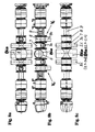
- FIGS. 8a to 8c An advantageous embodiment of the structural section 5, from which the hollow structure B1 a (Bia) of the valve manifold tree B1 (Bi) is composed, with both sides arranged and aligned leak-proof double seat valves V R , as he preferably in the horizontally arranged valve manifold tree B1 (Bi) for use comes (second direction variant), show the FIGS. 8a to 8c .
- the pipe connection 7a is arranged tangentially in the lower region of the valve housing 7.
- the hollow structure B1a (Bia), which in each case has the shape of a circular cross-section pipe section, opens in such a way in the upper region of the building section 5 that by avoiding a swamp-forming space in the building section 5 below the hollow structure B1a (Bia) shaping measures a complete flow of liquid from the latter is ensured in the valve housing 8 connected on both sides.
- the valve distributor tree Bi extends transversely, as a rule horizontally, and the first and possibly the second group of pipes 2.1 to 2.n and 3.1 to 3.n are arranged side by side in mutually parallel planes and on one side or on opposite sides Side of the hollow structure Bia and in its longitudinal axis L crossing planes passed this.
- a piping is used when the height below the tank Ti or the process unit Pi limited and thereby the arrangement of a valve manifold Bi with a rising from bottom to top, usually with a vertical course, is not possible and if at the same time the entire relevant piping below the outlet of the tank Ti or the process unit Pi is to be arranged.
Landscapes
- Engineering & Computer Science (AREA)
- Mechanical Engineering (AREA)
- General Engineering & Computer Science (AREA)
- Valve Housings (AREA)
- Pipeline Systems (AREA)
- Multiple-Way Valves (AREA)
- Tea And Coffee (AREA)
- General Preparation And Processing Of Foods (AREA)
- Lift Valve (AREA)
Abstract
Description
Die Erfindung betrifft eine Vorrichtung zur Verrohrung von Prozessanlagen der Nahrungsmittel- und Getränkeindustrie nach dem Oberbegriff des Anspruchs 1, wobei diese Vorrichtungen insbesondere dort Anwendung finden, wo die der Produktbearbeitung und dem Produkttransfer dienenden Prozessanlagen hohen mikrobiologischen Qualitätsanforderungen und Forderungen nach bester Reinigungsfähigkeit im Durchfluss (sog. CIP-Fähigkeit) unterliegen und wo eine kompakte und flexible Auslegung der Anlage erforderlich ist. Die Anwendung schließt auch Bereiche insbesondere der Pharmazie und der Biotechnologie ein.The invention relates to a device for piping of process equipment of the food and beverage industry according to the preamble of
Der gattungsbildende und wohl am weitesten verbreitete Stand der Technik auf dem vorgenannten Gebiet ist in
Die Zuführleitungen aus den verschiedenen Tanks und Prozessaggregaten werden zu einem Ventilblock (als VB bezeichnet) geführt und von dort beispielsweise an zugeordnete Abfüllmaschinen verteilt und angeschlossen. Die Anschlussstellen, an denen sich unverträgliche Medien gegenüberstehen können (beispielsweise Würze oder Hefe oder Jungbier und jeweils Reinigungsmittel), sind mit sogenannten vermischungssicheren Ventilen, typischerweise Doppelsitzventilen, ausgerüstet.The supply lines from the various tanks and process units are fed to a valve block (referred to as VB) and distributed from there, for example, to associated filling machines and connected. The connection points at which incompatible media can face each other (for example seasoning or yeast or young beer and in each case cleaning agents) are equipped with so-called mix-proof valves, typically double-seated valves.
Ein Vorteil dieses Verrohrungssystems ist, dass der Ventilblock kompakt ausgelegt werden kann, auch in Prozessanlagen, worin die Tanks und Prozessaggregate beliebig positioniert sind. Zusätzlich zu reduzierten Kosten und zu reduziertem Platzbedarf vereinfacht dies die Reinigung, Wartung und Überwachung der Prozessanlage.An advantage of this piping system is that the valve block can be made compact, even in process plants, where the tanks and process units are arbitrarily positioned. In addition to reduced costs and reduced space requirements, this simplifies the cleaning, maintenance and monitoring of the process plant.
Ein weiteres Verrohrungssystem ist zum Beispiel aus der
Bei dem vorgenannten Verrohrungssystem können die Funktionsventile entweder seitlich am Tankauslaufbaum, dem sog. Ventilverteilerbaum, oder senkrecht am Bodenflansch des Tanks befestigt werden. Diese Verrohrungstechnik minimiert deutlich die Entstehung von Kontamination und deren spätere Verteilung im Prozesssystem. Das vom Tank getrennt aufgebaute Rohrleitungssystem ermöglicht eine vollständige Produktentleerung und eine vom Tank unabhängige Reinigung. Im Vergleich zu den traditionellen Systemen mit vom Tank entfernt angeordneten sog. Ventilmatrixsystemen, bei denen eine Vielzahl von Ventilen zur Schaltung der vielfältigen Rohrleitungen des jeweiligen Prozesses in sog. Ventilblöcken zusammengefasst sind, verringert sich bei dieser neueren Verrohrungstechnik der instrumentelle Aufwand, während der Prozess für einen nahezu verlustfreien Produktionsbetrieb optimiert werden kann.In the aforementioned piping system, the function valves can either be attached to the side of the tank outlet tree, the so-called. Ventilverteilerbaum, or perpendicular to the bottom flange of the tank. This piping technique significantly minimizes the formation of contamination and its subsequent distribution in the process system. The piping system, separated from the tank, allows for complete product evacuation and tank-independent cleaning. In comparison with the traditional systems with so-called valve matrix systems arranged away from the tank, in which a multiplicity of valves for switching the manifold pipelines of the respective process are combined in so-called valve blocks, the instrumentation costs are reduced in this newer piping technique, while the process for a nearly lossless production operation can be optimized.
Der Ventilverteilerbaum ist als langgestreckter Hohlkörper ausgebildet, er ist im Wesentlichen senkrecht orientiert und er besitzt Anschlussöffnungen zum Verbinden seines Innenraumes mit Rohrleitungen eines Rohrsystems, die seitlich an dem Ventilverteilerbaum vorbeigeführt sind. In jeder Verbindung zwischen der Rohrleitung und der zugeordneten Anschlussöffnung ist ein in seinem Sitzbereich vermischungssicher ausgestaltetes Ventil angeordnet, das diese Verbindung in unmittelbarer Nähe zum Hohlkörper schaltet. Als vermischungssicheres Ventil kann dabei jeweils ein sog. Doppelsitzventil mit zwei relativ zueinander bewegbaren Schließgliedern oder ein sog. Doppeldichtventil mit zwei auf einem einzigen Schließglied in Hubrichtung beabstandeten Sitzdichtungen oder ein sog. leckagegesichertes Scheibenventil zur Anwendung kommen. Zwischen den axial beabstandeten Abdichtungsstellen des vermischungssicheren Ventils befindet sich ein Leckagehohlraum, der über wenigstens einen Verbindungsweg mit der Umgebung des Doppelsitzventils verbunden ist.The valve manifold is designed as an elongated hollow body, it is oriented substantially vertically and it has connection openings for connection its interior with piping of a pipe system, which are guided laterally on the valve manifold. In each connection between the pipe and the associated connection opening, a mixing-resistant valve configured in its seating area is arranged, which switches this connection in the immediate vicinity of the hollow body. In this case, a so-called double-seat valve with two closing elements movable relative to one another or a so-called double-sealing valve with two seat seals spaced apart on a single closing element in the stroke direction or a so-called leak-proof disk valve can be used as a mix-proof valve. Between the axially spaced sealing locations of the mixproof valve is a leakage cavity connected to the vicinity of the double seat valve via at least one communication path.
Als bevorzugtes vermischungssicheres Ventil findet in den in Rede stehenden Verrohrungssystemen bislang das vorg. Doppelsitzventil Verwendung, wobei letzteres konzentrisch ineinander angeordnete Ventilstangen für die Schließglieder aufweist, die einseitig durch das Ventilgehäuse hindurch- und aus diesem zu einem Antrieb herausgeführt sind. Ein Doppelsitzventil mit einer diesbezüglichen Schließglied- und Ventilstangenkonfiguration ist bereits aus der
Eine in der
Dabei ist das Ventil der
Die bekannte Rohrverzweigungsanordnung nach der
Aufgabe der Erfindung ist es, eine Vorrichtung zur Verrohrung der gattungsgemä-βen Art zu schaffen, die bei hoher Betriebssicherheit höchsten Anforderungen an die Qualität des in ihr behandelten fluiden Produktes gerecht wird, die insgesamt, einschließlich der vermischungssicheren Ventile, einfach, flexibel und kostengünstig aufgebaut ist und die bei allen in der Praxis vorkommenden Anordnungsvarianten des Ventilverteilerbaums in Bezug zum zugeordneten Prozessaggregat oder Tank der Prozessanlage im jeweiligen Ventilverteilerbaum weitestgehend die gleichen technologischen Bedingungen und Zustandsgrößen wie im Prozessaggregat oder Tank abbildet.The object of the invention is to provide a device for piping the gattungsgemä-βen type, which meets high demands on the quality of the treated fluid product in high reliability, the total, including the mix-safe valves, simple, flexible and inexpensive is constructed and in all occurring in practice arrangement variants of the valve manifold tree in relation to the associated process unit or tank of the process plant in each valve manifold tree largely the same technological conditions and state variables as in the process unit or tank maps.
Die Aufgabe wird durch eine Vorrichtung zur Verrohrung mit den Merkmalen des Anspruchs 1 gelöst. Vorteilhafte Ausgestaltungen der vorgeschlagenen Vorrichtung gemäß der Erfindung sind Gegenstand der Unteransprüche.The object is achieved by a device for piping with the features of
Der Kern der Erfindung besteht darin, dass die aus dem Rohrsystem zu- oder abzuführenden fluiden Produkte das vom Ventilverteilerbaum begrenzte hohle Gebilde auf dem Weg über Anschlussöffnungen durchströmen und dass das jeweilige Fluid in diesem hohlen Gebilde in unmittelbarer Nähe zu dessen Begrenzung von den an die zugeordnete(n) Anschlussöffnung(en) heran- und an dem hohlen Gebilde vorbeigeführten Rohrleitungen des Rohrsystems durch ein vermischungssicheres Ventil wahlweise, schaltbar und vermischungssicher abtrennbar ist. Dabei mündet der jeweilige Ventilverteilerbaum unmittelbar im unteren Tankboden eines jeweils zugeordneten Tanks der Prozessanlage aus (erste Anordnungsvariante) oder/und der jeweilige Ventilverteilerbaum ist über eine zugeordnete Rohrverbindung mit einem zugeordneten Prozessaggregat oder Tank der Prozessanlage verbunden und die Rohrverbindung mündet in das tank- oder prozessaggregatseitige Ende des Ventilverteilerbaumes ein (zweite Anordnungsvariante). Dadurch werden die Verrohrungssysteme für die unterschiedlichsten Anwendungen denkbar einfach.The essence of the invention consists in that the fluid products to be supplied or discharged from the pipe system flow through the hollow structures delimited by the valve manifold on the way via connection openings and that the respective fluid in this hollow structure is in close proximity to its boundary from the associated (n) connection opening (s) zoom in and on the hollow structure passing piping of the pipe system by a mix-safe valve optional, switchable and mix safe separation. In this case, the respective valve manifold opens directly into the lower tank bottom of a respectively assigned tank of the process plant (first arrangement variant) or / and the respective valve manifold is connected via an associated pipe connection with an associated process unit or tank of the process plant and the pipe connection opens into the tank or process unit side End of the valve manifold tree (second arrangement variant). This makes the piping systems for the most diverse applications extremely easy.
Eine vorteilhafte Ausführungsform sieht vor, dass bei der ersten Richtungsvariante, bei der der Ventilverteilerbaum einen von unten nach oben aufsteigenden, im Regelfall einen senkrechten Verlauf aufweist, die erste und die zweite Gruppe Rohrleitungen in jeweils reihenförmiger Anordnung untereinander, auf einander gegenüberliegenden Seiten des hohlen Gebildes, in zueinander und zur Längsachse des hohlen Gebildes parallelen Ebenen angeordnet sind. Eine derartige Verrohrung ist äußerst kompakt, raumsparend und übersichtlich.An advantageous embodiment provides that in the first directional variant, in which the valve manifold tree ascends from bottom to top, usually a vertical course, the first and the second group of pipes in each row-like arrangement with each other, on opposite sides of the hollow structure , in each other and to the longitudinal axis of the hollow structure are arranged in parallel planes. Such piping is extremely compact, space-saving and clear.
Ein anderer Vorschlag sieht vor, dass bei der zweiten Richtungsvariante, bei der der Ventilverteilerbaum quer, im Regelfall waagerecht verläuft, die erste und die zweite Gruppe Rohrleitungen jeweils in zueinander parallelen Ebenen nebeneinander angeordnet und auf einer Seite oder auf gegenüberliegenden Seiten des hohlen Gebildes und in sich mit dessen Längsachse kreuzenden Ebenen an diesem vorbeigeführt sind. Eine derartige Verrohrung kommt dann zur Anwendung, wenn die Bauhöhe unterhalb des Tanks oder des Prozessaggregats begrenzt und dadurch die Anordnung eines Ventilverteilerbaumes mit einem von unten nach oben aufsteigenden, im Regelfall mit einem senkrechten Verlauf, nicht möglich ist und wenn gleichzeitig die gesamte relevante Verrohrung unterhalb des Auslaufs des Tanks oder des Prozessaggregats anzuordnen ist.Another proposal provides that in the second directional variant, in which the valve manifold crosswise, as a rule, runs horizontally, the first and second group of pipes arranged side by side in mutually parallel planes and on one side or on opposite sides of the hollow structure and in Placed with its longitudinal axis crossing planes are past this. Such a piping is used when the height below the tank or the processing unit limited and thereby the arrangement of a valve manifold with a rising from bottom to top, usually with a vertical course, is not possible and if at the same time the entire relevant piping below the outlet of the tank or the process unit is to be arranged.
Das hohle Gebilde erlaubt einen sehr einfachen Anschluss des vermischungssicheren Ventils, wenn es im Umfassungsbereich seiner Anschlussöffnung als Ringgehäuse ausgebildet ist, das die beiden Sitzflächen aufnimmt und dem Anschluss des Ventilgehäuses dient.The hollow structure allows a very simple connection of the mix-proof valve, if it is formed in the peripheral area of its connection opening as an annular housing which receives the two seats and serves to connect the valve housing.
Die Ausführung des hohlen Gebildes gestaltet sich besonders einfach, wenn es, wie dies weiterhin vorgesehen ist, als zylindrisches Rohr ausgebildet ist.The execution of the hollow structure is particularly simple if it, as is still provided, is designed as a cylindrical tube.
Das hohle Gebilde lässt sich restlos entleeren und einwandfrei reinigen, wenn sein dem jeweiligen Tank oder der jeweiligen vom Prozessaggregat oder Tank herangeführten Rohrverbindung abgewandtes unterstes Ende mit einem dritten Rohrsystem verbunden ist.The hollow structure can be completely emptied and cleaned properly, if its the lower end remote from the respective tank or the respective pipe connection brought from the process unit or tank is connected to a third pipe system.
Die Vorrichtung wird besonders übersichtlich und einfach, wenn die Rohrleitungen, gemäß einem weiteren Vorschlag, jeweils als durchgehende, allen Rohrverbindungen in gleicher Funktion zugeordnete Rohrleitungen (Füllen; Entleeren; Rohrreinigung) ausgeführt sind.The device becomes particularly clear and simple if, according to a further proposal, the pipelines are each designed as continuous pipelines (filling, emptying, pipe cleaning) assigned to all pipe connections in the same function.
Einfache und übersichtliche Rohrleitungsführungen ergeben sich im Rahmen des Verrohrungssystems, wenn die Ventilverteilerbäume eine reihen- oder matrixförmige Anordnung aufweisen.Simple and clear pipe guides arise in the context of the piping system, if the valve manifolds have a series or matrix-shaped arrangement.
Alternativ zur Ausgestaltung des hohlen Gebildes in Form eines zylindrischen Rohres ist weiterhin vorgesehen, dass das hohle Gebilde jeweils aus einer Aggregation von einzelnen Gebildeabschnitten zusammengesetzt ist, die in Richtung der Längsachse des hohlen Gebildes fluiddurchgängig miteinander verbunden sind und jeweils mindestens eine Anschlussöffnung aufweisen. Bei diesen Gehäuseteilen kann es sich entweder um diskrete, separate Teile handeln, die zu dem hohlen Gebilde in seiner Gesamtheit gefügt werden, oder um ein einstückiges Ganzes, bei dem die einzelnen Gehäuseteile stoffschlüssig miteinander verbunden sind.As an alternative to the embodiment of the hollow structure in the form of a cylindrical tube, it is further provided that the hollow structure is composed in each case of an aggregation of individual structural sections which are fluidly interconnected in the direction of the longitudinal axis of the hollow structure and each have at least one connection opening. These housing parts may be either discrete, separate parts that are joined to the hollow structure in its entirety, or a one-piece, in which the individual housing parts are materially interconnected.
Bei beiden vorg. Ausführungsvarianten sind, gemäß einem weiteren Vorschlag, die Gebildeabschnitte in Form von Gehäuseteile unterschiedlich groß ausgebildet, so dass an diesen Gehäuseteilen im Bedarfsfall, wie dies gleichfalls vorgesehen ist, wenigstens eine Anschlussöffnung ausgeführt werden kann, die einen von der Größe des jeweils zugeordneten Gehäuseteils abhängigen Durchtrittsquerschnitt aufweist. Anschlussöffnungen mit unterschiedlich großen Durchtrittsquerschnitten an einem Gehäuseteil sind gleichfalls vorgesehen. Durch diese Gestaltungsvielfalt lässt sich das hohle Gebilde in allen seinen durchströmten Bereichen an die strömungstechnischen Erfordernisse der angeschlossenen Rohrleitungen unterschiedlicher Nennweite anpassen.In both vorg. Embodiments are, according to another proposal, the sections of the building in the form of housing parts of different sizes, so that at these housing parts, if necessary, as is also provided, at least one connection opening can be performed, which is dependent on the size of the respective associated housing part passage cross-section having. Connection openings with different sized passage cross sections on a housing part are also provided. Due to this design variety, the hollow structure in all its areas through which it flows can be adapted to the fluidic requirements of the connected pipelines of different nominal widths.
Ausführungsbeispiele der Vorrichtung zur Verrohrung von Prozessanlagen im Rahmen der ersten und der zweiten Anordnungsvariante sowie in der ersten und der zweiten Richtungsvariante gemäß der Erfindung sind in den Figuren der Zeichnung dargestellt und werden nachfolgend hinsichtlich Aufbau und Funktion beschrieben. Es zeigen
-
Figur 1 - in Form einer teilweise schematisch dargestellten Perspektive eine erfindungsgemäße Vorrichtung mit drei Ventilverteilerbäumen in reihenförmig fluchtender Anordnung, wobei an den hohlen Gebilden der beiden vorderen Ventilverteilerbäume jeweils beidseitig, einander gegenüberliegend, in zueinander und zur Längsachse des hohlen Gebildes parallelen Ebenen Rohrsysteme vorbeigeführt und angeschlossen sind und das dritte hohle Gebilde vor einer Wand angeordnet und einseitig an das zugeordnete Rohrsystem angeschlossen ist;
-
Figur 2 - einen Mittelschnitt durch den vorderen Ventilverteilerbaum gemäß
Figur 1 - Figur 2a
- in vergrößerter Darstellung einen Mittelschnitt durch einen der drei das hohle Gebilde gemäß
Figur 2 bildenden Gebildeabschnitte mit einem im Umfassungsbereich seiner Anschlussöffnungen jeweils vorgesehenen Ringgehäuse; -
Figur 3 - in weiter vergrößerter Darstellung der Mittelschnitt durch einen der Gebildeabschnitte gemäß
Figur 2 mit den beidseitig angeschlossenen vermischungssicheren Doppelsitzventilen, wobei diese jeweils in ihrem Schließglied- und Ventilgehäusebereich dargestellt sind; - Figur 4
- in Ansicht eine vorteilhafte erste Ausführungsform des Gebildeabschnitts in stoffschlüssiger Verbindung mit einem auf jeder Seite angeordneten, im Nenndurchmesser jeweils gleichen Ventilgehäuse, das jeweils beidseitig tangential angeordnete Rohranschlüsse besitzt, wobei die Betrachtungsrichtung, bezogen auf die Anordnungslage, von unten erfolgt und die Verbindungsstellen zwischen dem Gebildeabschnitt und dem jeweiligen Ventilgehäuse jeweils in einem meridian verlaufenden Teilschnitt dargestellt sind;
- Figur 4a
- einen Schnitt durch den Gebildeabschnitt gemäß
Figur 4 entsprechend einem dort mit B-B gekennzeichneten Schnittverlauf; - Figur 4b
- die Draufsicht auf den Gebildeabschnitt gemäß
Figur 4 ; - Figur 4c
- die Seitenansicht auf den Gebildeabschnitt gemäß
Figur 4 , wobei die Darstellung Teilschnitte durch die beiderseitigen Klemmflansche und Einzelheiten im Bereich der Verbindungsstellen zwischen dem Gebildeabschnitt und den Ventilgehäusen entsprechend einem inFigur 4 mit C-C gekennzeichneten Schnittverlauf enthält; -
Figur 5 - in Ansicht eine vorteilhafte zweite Ausführungsform des Gebildeabschnitts in stoffschlüssiger Verbindung mit einem auf jeder Seite angeordneten, im Nenndurchmesser jeweils unterschiedlichen Ventilgehäuse, von denen das eine beidseitig, mittig angeordnete Rohranschlüsse und das andere einen einseitig, mittig angeordneten Rohranschluss besitzt, wobei die Betrachtungsrichtung, bezogen auf die Anordnungslage, von unten erfolgt und die Verbindungsstellen zwischen dem Gebildeabschnitt und dem jeweiligen Ventilgehäuse jeweils in einem meridian verlaufenden Teilschnitt dargestellt sind;
- Figur 5a
- einen Schnitt durch den
Gebildeabschnitt gemäß Figur 5 entsprechend einem dort mit D-D gekennzeichneten Schnittverlauf; - Figur 5b
- die Draufsicht auf den
Gebildeabschnitt gemäß Figur 5 ; - Figur 5c
- die Seitenansicht auf den
Gebildeabschnitt gemäß Figur 5 , wobei die Darstellung Teilschnitte durch die beiderseitigen Klemmflansche und Einzelheiten im Bereich der Verbindungsstellen zwischen Gebildeabschnitt und Ventilgehäusen entsprechend einem inFigur 5 -
Figur 6 - in perspektivischer Darstellung einen Ventilverteilerbaum mit den beidseitig angeschlossenen vermischungssicheren Doppelsitzventilen und darüber mit einem einseitig angeschlossenen vermischungssicheren Doppelsitzventil, wobei die Gebildeabschnitte in Form von Gehäuseteilen unterschiedlich groß ausgebildet sind;
-
Figur 7 - in perspektivischer Darstellung die erfindungsgemäße Vorrichtung in der aus
Figur 1 ersichtlichen zweiten Anordnungsvariante mit einseitig am senkrecht angeordneten Ventilverteilerbaum (erste Richtungsvariante) angeschlossenen vermischungssicheren Doppelsitzventilen und -
Figuren 8a bis 8c - in Unteransicht, Ansicht und Draufsicht eine spezielle Ausführungsform eines Gebildeabschnitts des hohlen Gebildes mit beiderseits daran angeordneten leckagegesicherten Doppelsitzventilen, wobei es sich um einen Ventilverteilerbaum in waagerechter Anordnung (zweite Richtungsvariante der ersten oder zweiten Anordnungsvariante) handelt.
- FIG. 1
- in the form of a partially schematically illustrated perspective, a device according to the invention with three valve manifolds in a row aligned arrangement, wherein on the hollow structures of the two front valve manifolds on both sides, opposite each other, in parallel to each other and to the longitudinal axis of the hollow structure piping systems are passed and connected and the third hollow structure arranged in front of a wall and connected on one side to the associated pipe system;
- FIG. 2
- a central section through the front valve manifold according to
FIG. 1 corresponding to a section line marked there with AA , wherein corresponding center sections of the two other valve manifolds lead in the present embodiment in the same components to the same representations; - FIG. 2a
- in an enlarged view a central section through one of the three the hollow structure according to
FIG. 2 forming sections with a housing provided in the peripheral region of its connection openings ring housing; - FIG. 3
- in a further enlarged view of the central section through one of the sections according to
FIG. 2 with the mixproof double-seat valves connected on both sides, wherein these are each shown in their closing member and valve housing area; - FIG. 4
- in view of an advantageous first embodiment of the structural section in material connection with a arranged on each side, in each case the same nominal valve housing, each having tangentially arranged pipe connections on both sides, wherein the viewing direction, based on the arrangement position, from below and the connection points between the building section and the respective valve housing are each shown in a meridian extending partial section;
- FIG. 4a
- a section through the structure section according to
FIG. 4 according to a section line marked BB there; - FIG. 4b
- the top view of the structure section according to
FIG. 4 ; - Figure 4c
- the side view of the structure section according to
FIG. 4 , The representation of partial sections through the mutual clamping flanges and details in the region of the connection points between the structural section and the valve housings corresponding to one inFIG. 4 Contains CC marked cutting course; - FIG. 5
- in view of an advantageous second embodiment of the structural section in material connection with a arranged on each side, the nominal diameter respectively different valve housing, one of which has on both sides, centrally located pipe connections and the other has a one-sided, centrally located pipe connection, wherein the viewing direction, based on the arrangement position, taken from below and the connection points between the structural section and the respective valve housing are each shown in a meridian extending partial section;
- FIG. 5a
- a section through the structure section according to
FIG. 5 according to a sectional course marked there with DD ; - FIG. 5b
- the top view of the structure section according to
FIG. 5 ; - FIG. 5c
- the side view of the structure section according to
FIG. 5 , The representation of partial sections through the mutual clamping flanges and details in the region of the connection points between the building section and valve housings corresponding to one inFIG. 5 Contains EE marked cutting course; - FIG. 6
- a perspective view of a valve manifold with the mixed-side double-seat valves connected to both sides and above with a mixing-proof double-seat valve connected on one side, wherein the component sections are designed differently in the form of housing parts;
- FIG. 7
- in a perspective view of the device according to the invention in the
FIG. 1 apparent second arrangement variant with one-sided on the vertically arranged valve manifold tree (first direction variant) connected mixproof double-seat valves and - FIGS. 8a to 8c
- in a bottom view, view and plan view of a special embodiment of a structural portion of the hollow structure with both sides arranged thereon leak-proof double seat valves, which is a valve manifold tree in a horizontal arrangement (second direction variant of the first or second arrangement variant).
Eine Vorrichtung 1 zur Verrohrung von Prozessanlagen bestehe beispielhaft aus drei Ventilverteilerbäumen B1, B2 und B3, im allgemeinsten Falle aus B1 bis Bn Ventilverteilerbäumen, die vorzugsweise reihenförmig und miteinander fluchtend nebeneinander angeordnet sind. Jeder Ventilverteilerbaum B1, B2, B3 (Bi) ist als langgestrecktes hohles Gebilde B1a, B2a, B3a (im allgemeinsten Falle B1a bis Bna; Bia), vorzugsweise in Form eines zylindrischen Rohres oder aus einer Aggregation von einzelnen Gebildeabschnitten 5 (s.
Die erste Gruppe Rohrleitungen 2.1, 2.2, 2.3 und die zweite Gruppe Rohrleitungen 3.1, 3.2, 3.3 sind jeweils in reihenförmiger Anordnung untereinander und, in Bezug auf die vorderen beiden Ventilverteilerbäume B1 und B2, auf einander gegenüberliegenden Seiten des hohlen Gebildes B1a, B2a, in zwei zueinander und zur Längsachse des hohlen Gebildes parallelen Ebenen angeordnet und an diesem vorbeigeführt (beidseitige Anordnung der vermischungssicheren Doppelsitzventile VR). Das dritte hohle Gebilde B3a befindet sich beispielsweise unmittelbar vor einer vertikalen Wand, so dass an diesem nur das erste Rohrsystem 2 vorbeigeführt werden und Anschluss finden soll (einseitige Anordnung der vermischungssicheren Doppelsitzventile VR).The first group of pipes 2.1, 2.2, 2.3 and the second group of pipes 3.1, 3.2, 3.3 are each arranged in a row with each other and, with respect to the front two Ventilverteilerbäume B1 and B2, on opposite sides of the hollow structure B1a, B2a, in two parallel to each other and to the longitudinal axis of the hollow structure arranged parallel planes and past this (two-sided arrangement of mix safe double seat valves V R ). The third hollow structure B3a is located, for example, directly in front of a vertical wall, so that only the
Eine perspektivische Darstellung der dem hinteren Ventilverteilerbaum B3 im Wesentlichen entsprechende Anordnung zeigt
Bei der in
Wie dies in
Bei der zweiten Anordnungsvariante ist das obere Ende des ersten Ventilverteilerbaumes B1 über eine erste Rohrverbindung R1 beispielhaft mit einem ersten Prozessaggregat P1 verbunden, der zweite Ventilverteilerbaum B2 ist über eine zweite Rohrverbindung R2 mit einem ersten Tank T1 und der dritte Ventilverteilerbaum B3 ist über eine dritte Rohrverbindung R3 mit einem zweiten Prozessaggregat P2 verbunden. Die Rohrverbindungen R1, R2 und R3 sind im allgemeinsten Falle Rohrverbindungen R zugeordnet, die aus einer Anzahl i = 1 bis n Rohrverbindungen R1 bis Rn bestehen können.In the second arrangement variant, the upper end of the first valve manifold B1 is connected to a first process unit P1 via a first pipe connection R1, the second valve manifold B2 is connected to a first tank T1 via a second pipe connection R2 and the third valve manifold B3 is connected via a third pipe connection R3 connected to a second process unit P2. The pipe connections R1, R2 and R3 are assigned in the most general case pipe connections R, which may consist of a number i = 1 to n pipe connections R1 to Rn.
Die Prozessaggregate P oder die Tanks T können bei der zweiten Anordnungsvariante jede Anordnung und Positionierung einnehmen, während die Ventilverteilerbäume B1 bis Bn vorzugsweise reihen- oder matrixförmig angeordnet sind. Bei den dargestellten Rohrverbindung R1 bis R3 (R1 bis Rn) kann es sich im Bereich ihres an den Ventilverteilerbaum B1 bis B3 (B1 bis Bn) angeschlossenen Endabschnitts jeweils um einen senkrechten oder einen wie auch immer geneigten Endabschnitt handeln. Der geneigte Endabschnitt, der im Grenzfall waagerecht verläuft, findet mit einem entsprechenden Rohrbogen Anschluss an dem tank- oder prozessaggregatseitigen Ende des jeweiligen Ventilverteilerbaumes B1 bis B3 (B1 bis Bn).The process units P or the tanks T can assume any arrangement and positioning in the second arrangement variant, while the valve manifolds B1 to Bn are preferably arranged in rows or in a matrix. In the illustrated pipe joint R1 to R3 (R1 to Rn) may be in the region of their connected to the valve manifold tree B1 to B3 (B1 to Bn) end portion in each case a vertical or any inclined end portion. The inclined end portion, which extends horizontally in the limiting case, with a corresponding pipe bend connection to the tank or process unit end of the respective valve manifold tree B1 to B3 (B1 to Bn).
Die Ventilverteilerbäume Bi können, wie später noch im Einzelnen dargelegt wird, auch waagerecht angeordnet sein (zweite Richtungsvariante). Für die Verbindung des jeweiligen waagerecht angeordneten Ventilverteilerbaumes Bi mit dem zugeordneten Tank Ti oder Prozessaggregat Pi gelten die vorstehenden Ausführungen sinngemäß.The valve manifolds Bi can, as will be explained in detail later, also be arranged horizontally (second direction variant). For the connection of the respective horizontally arranged valve manifold tree Bi with the associated tank Ti or process unit Pi, the above statements apply mutatis mutandis.
Das Ventilgehäuse 7 ist Teil des vermischungssicheren Doppelsitzventils VR. An das Ventilgehäuse 7 schließt sich, in Längsrichtung des Doppelsichtventils VR gesehen, seitlich ein Leckage- und Ablaufgehäuse 8 (
Das Doppelsitzventil VR ist mit zwei seriell angeordneten Schließglieder 10, 11 ausgebildet, die in der Schließstellung des Ventils das Überströmen von Fluiden vom hohlen Gebilde Bia bzw. von dem Gebildeabschnitt 5 in das Ventilgehäuse 7 verhindern. Die Schließglieder 10, 11 begrenzen sowohl in der Schließ- als auch in der Offenstellung einen Leckagehohlraum 14, der mindestens einen Verbindungsweg mit der Umgebung des Doppelsitzventils VR aufweist. Im dargestellten Ausführungsbeispiel sind der Innenraum des Leckage- und Ablaufgehäuses 8 und sein Ablaufanschluss 8a Teil dieses Verbindungsweges. Das erste Schließglied 10 ist mit einer ersten Ventilstange 10a und das zweite Schließglied 11 ist mit einer zweiten Ventilstange 11a verbunden, die konzentrisch ineinander angeordnet sind und einseitig durch das erste Ventilgehäuse 7 hindurch- und aus diesem über das Leckage- und Ablaufgehäuse 8 zu dem Antrieb herausgeführt sind. Die Führung und Abdichtung des zweiten Schließgliedes 11 in einem Bereich 21 - 25 zwischen den Gehäusen 7, 8 sowie der zweiten Ventilstange 11a in einem Bereich 16 - 21 zwischen den Gehäusen 8, 9 ist nicht im Einzelnen beschrieben.The double seat valve V R is formed with two serially arranged closing
Eine vorteilhafte Ausführungsform des Gebildeabschnitts 5, seiner beiden Ringgehäuse 6 und des sich jeweils daran anschließenden Ventilgehäuses 7 zeigen die
Die
Die
Das zweite Schließglied 11 weist an seinem die zweite Sitzdichtung aufnehmenden Endabschnitt innenseits eine zylindrische Aufnahmebohrung auf, die durchmessergleich mit der zylindrischen ersten Sitzfläche 6b ausgebildet ist. In der Schließstellung des zweiten Schließgliedes 11 gehen die Aufnahmebohrung und die erste Sitzfläche 6b bündig ineinander über, so dass leckagefreies Schalten mit nur zwei Sitzdichtungen gegeben ist.The
Das als Hohlstange ausgebildete zweite Schließglied 11 ist an seiner äußeren Mantelfläche zylindrisch ausgebildet, und es mündet in das Leckage- und Ablaufgehäuse 8 aus (
Das zweite Schließglied 11 geht im Bereich des Innenraumes des Leckage- und Ablaufgehäuses 8 auf die im Durchmesser kleinere zweite Ventilstange 11a über (
Das Leckage- und Ablaufgehäuse 8 ist laternengehäuseseitig durch einen Deckelteil 16 verschlossen, der gehäuseseitig mittels einer weiteren Gehäusedichtung 21 und ventilstangenseitig mittels einer Stangendichtung abgedichtet ist.The leakage and drain
Die dargestellte horizontale Anordnung des Doppelsitzventils VR stellt eine bevorzugte Anordnung dar, die deshalb möglich ist, weil selbst in dieser Lage durch die vorstehend beschriebene Ausgestaltung des Doppelsitzventils VR eine Selbstentleerung des Leckagehohlraumes 14 ohne Pfützenbildung möglich ist. Im allgemeinsten Falle ist eine hinsichtlich möglicher Einbaulagen aus der
Das hohle Gebilde B1a bis Bna kann jeweils auch aus einer Aggregation von einer Anzahl einzelner Gebildeabschnitten 5 zusammengesetzt sein (s. hierzu
Das am unteren Gebildeabschnitt 5 linksseitig angeordnete Ventilgehäuse 7 mündet über den senkrecht nach unten orientierten Rohranschluss 7a in eine molchbare zweite Rohrleitung 3.2* aus der zweiten Gruppe Rohrleitungen des zweiten Rohrsystems 3 ein. Diese Rohrleitung 3.2* ist durchgängig mit einem unversperrten, Kreisform aufweisenden Durchtrittsquerschnitt ausgeführt, wodurch sie für einen Molch durchgängig ist; sie ist an dem zugeordneten Ventilgehäuse 7 des vermischungssicheren Doppelsitzventils VR vorbeigeführt und mit letzterem fluidgängig verbunden. Prinzipiell kann jede der Rohrleitungen 2.1 bis 2.n der ersten Gruppe Rohrleitungen des ersten Rohrsystems 2 und jede der Rohrleitungen 3.1 bis 3.n der zweiten Gruppe Rohrleitungen des zweiten Rohrsystems 3 und ggf. auch das dritte Rohrsystem 4 in der vorbeschriebenen Weise molchbar ausgeführt werden. Am oberen Gebildeabschnitt 5 (
Das jeweilige Ventilgehäuse 7 ist Teil des vermischungssicheren Doppelsitzventils VR. An das Ventilgehäuse 7 schließt sich, in Längsrichtung des Doppelsichtventils VR gesehen, seitlich das Leckage- und Ablaufgehäuse 8 mit dem Ablaufanschluss 8a sowie ein nicht näher bezeichneter Antrieb an, wobei letzterer mit dem Leckage- und Ablaufgehäuse 8 über das Laternengehäuse 9 verbunden ist.The
Die an einem senkrecht angeordneten Ventilverteilerbaum B3 (im allgemeinsten Falle Bi) jeweils einseitige Anordnung von drei übereinander angeordneten vermischungssicheren Doppelsitzventilen VR entsprechend der in
Eine vorteilhafte Ausführungsform des Gebildeabschnitts 5, aus dem sich das hohle Gebilde B1 a (Bia) des Ventilverteilerbaumes B1 (Bi) zusammensetzt, mit beiderseits angeordneten und miteinander fluchtenden leckagesicherten Doppelsitzventilen VR, wie er vorzugsweise im waagerecht angeordneten Ventilverteilerbaum B1 (Bi) zur Anwendung kommt (zweite Richtungsvariante), zeigen die
Bei der zweiten Richtungsvariante verläuft der Ventilverteilerbaum Bi quer, im Regelfall waagerecht, und die erste und ggf. die zweite Gruppe Rohrleitungen 2.1 bis 2.n und 3.1 bis 3.n sind jeweils in zueinander parallelen Ebenen nebeneinander angeordnet und auf einer Seite oder auf gegenüberliegenden Seiten des hohlen Gebildes Bia und in sich mit dessen Längsachse L kreuzenden Ebenen an diesem vorbeigeführt. Eine derartige Verrohrung kommt dann zur Anwendung, wenn die Bauhöhe unterhalb des Tanks Ti oder des Prozessaggregats Pi begrenzt und dadurch die Anordnung eines Ventilverteilerbaumes Bi mit einem von unten nach oben aufsteigenden, im Regelfall mit einem senkrechten Verlauf, nicht möglich ist und wenn gleichzeitig die gesamte relevante Verrohrung unterhalb des Auslaufs des Tanks Ti oder des Prozessaggregats Pi anzuordnen ist.In the second direction variant, the valve distributor tree Bi extends transversely, as a rule horizontally, and the first and possibly the second group of pipes 2.1 to 2.n and 3.1 to 3.n are arranged side by side in mutually parallel planes and on one side or on opposite sides Side of the hollow structure Bia and in its longitudinal axis L crossing planes passed this. Such a piping is used when the height below the tank Ti or the process unit Pi limited and thereby the arrangement of a valve manifold Bi with a rising from bottom to top, usually with a vertical course, is not possible and if at the same time the entire relevant piping below the outlet of the tank Ti or the process unit Pi is to be arranged.
Aus dem oben Genannten wird verständlich, dass verschiedene Modifikationen und Varianten der Vorrichtung zur Verrohrung von Prozessanlagen der Nahrungsmittel- und Getränkeindustrie realisiert werden können, ohne vom neuen Konzept der vorliegenden Erfindung abzuweichen. Dies ist so zu verstehen, dass keine Beschränkung auf die speziellen Ausführungsformen beabsichtigt ist, welche hier illustriert worden sind. Die Offenbarung soll alle solchen Abwandlungen umfassen, die sich innerhalb des von den Ansprüchen beanspruchten Schutzbereichs befinden.From the above, it will be understood that various modifications and variations of the apparatus for piping food and beverage process equipment can be realized without departing from the novel concept of the present invention. It is to be understood that it is not intended to be limited to the specific embodiments illustrated herein. The disclosure is intended to cover all such modifications as are within the scope of the claims claimed by the claims.
- 11
- Vorrichtungcontraption
- 22
- erstes Rohrsystemfirst pipe system
- 2.1, 2.2, ..., 2.n2.1, 2.2, ..., 2.n
- erste Gruppe Rohrleitungenfirst group of pipelines
- 2.i2.i
- eine der Rohrleitungen aus der ersten Gruppeone of the pipelines from the first group
- 2.12.1
- erste Rohrleitung aus der ersten Gruppefirst pipeline from the first group
- 2.22.2
- zweite Rohrleitung aus der ersten Gruppesecond pipeline from the first group
- 33
- zweites Rohrsystem (z.B. Entleeren)second pipe system (e.g., emptying)
- 3.1, 3.2, ..., 3.n3.1, 3.2, ..., 3.n
- zweite Gruppe Rohrleitungensecond group of pipelines
- 3.i3.i
- eine der Rohrleitungen aus der zweiten Gruppeone of the pipes from the second group
- 3.13.1
- erste Rohrleitung aus der zweiten Gruppefirst pipeline from the second group
- 3.23.2
- zweite Rohrleitung aus der zweiten Gruppesecond pipeline from the second group
- 3.2*3.2 *
- molchbare zweite Rohrleitung aus der zweiten Gruppepiggable second pipeline from the second group
- 44
- drittes Rohrsystem (z.B. Reinigung)third pipe system (e.g., cleaning)
- 55
- Gebildeabschnittstructure section
- 66
- Ringgehäusering case
- 6a6a
- Anschlussöffnungport opening
- 6b6b
- erste Sitzflächefirst seat
- 6c6c
- zweite Sitzflächesecond seat
- 6d6d
- zylindrische Ausnehmungcylindrical recess
- 77
- erstes Ventilgehäusefirst valve housing
- 7a7a
- Rohranschlusspipe connection
- 7b7b
- erster Klemmflanschfirst clamping flange
- 7*7 *
- zweites Ventilgehäusesecond valve housing
- 7a*7a *
- modifizierter Rohranschlussmodified pipe connection
- 7b*7b *
- zweiter Klemmflanschsecond clamping flange
- 88th
- Leckage- und AblaufgehäuseLeakage and drain housing
- 8a8a
- Ablaufanschlussdrain connection
- 8b8b
- dritter Klemmflanschthird clamping flange
- 99
- Laternengehäuselantern housing
- 9a9a
- Verschlussplatteclosing plate
- 9b9b
- vierter Klemmflanschfourth clamping flange
- 1010
- erstes Schließglied (Schieberkolben)first closing member (spool)
- 10a10a
- erste Ventilstangefirst valve rod
- 1111
- zweites Schließglied (Sitzteller)second closing element (seat plate)
- 11 a11 a
- zweite Ventilstange (Hohlstange)second valve rod (hollow rod)
- 1212
- erste Sitzdichtungfirst seat seal
- 1313
- zweite Sitzdichtungsecond seat seal
- 1414
- Leckagehohlraumleakage cavity
- 1616
- Deckelteilcover part
- 2121
- Gehäusedichtunghousing seal
- 2222
- Drainageringdrainage ring
- 22a22a
- Drainagebohrungdrain hole
- 2828
- SpülanschlussFlushing connection
- B1 bis BnB1 to Bn
- VentilverteilerbaumValve manifold tree
- BiBi
- einer der Ventilverteilerbäume B1 bis Bnone of the valve manifolds B1 to Bn
- B1a bis BnaB1a to Bna
- hohles Gebildehollow structure
- BiaBia
- der Rohrleitung Ri zugeordnetes hohles Gebilde B1 a bis Bnathe pipe Ri associated hollow structure B1 a to Bna
- Bia.1 bis Bia.mBia.1 to Bia.m
-
Gehäuseteile 1 bis m des hohlen Gebildes Bia
Housing parts 1 to m of the hollow structure Bia - LL
- Längsachse des hohlen Gebildes/VentilverteilerbaumesLongitudinal axis of the hollow structure / valve manifold tree
- PP
- Prozessaggregat (allgemein)Process unit (general)
- P1P1
- erstes Prozessaggregatfirst process unit
- P2P2
- zweites Prozessaggregatsecond process unit
- P3P3
- drittes Prozessaggregatthird process unit
- Pipi
- i-tes Prozessaggregati th process unit
- Pnpn
- n-tes Prozessaggregatnth process unit
- RR
- Rohrverbindungen (allgemein); die an das obere Ende des jeweiligen Ventilverteilerbaumes B1 bis Bn herangeführt istPipe joints (general); which is brought to the upper end of the respective valve manifold tree B1 to Bn
- R1R1
- erste Rohrverbindungfirst pipe connection
- R2R2
- zweite Rohrverbindungsecond pipe connection
- R3R3
- dritte Rohrverbindungthird pipe connection
- RiRi
- Ventilverteilerbaum Bi zugeordnete RohrverbindungValve distributor tree Bi associated pipe connection
- Rnrn
- n-te Rohrverbindungnth pipe connection
- TT
- Tank (allgemein)Tank (general)
- T1T1
- erster Tankfirst tank
- T2T2
- zweiter Tanksecond tank
- T3T3
- dritter Tankthird tank
- TiTi
- i-ter Tanki-th tank
- TnTn
- n-ter Tanknth tank
- T1a bis TnaT1a to Tna
- unterer Tankboden des jeweiligen Tanks T1 bis Tnlower tank bottom of the respective tank T1 to Tn
- TiaTia
- i-ter Tankbodeni-th tank bottom
- VR V R
- DoppelsitzventilDouble seat valve
Claims (12)
dadurch gekennzeichnet,
dass die Vorrichtung (1) aus wenigstens einem Ventilverteilerbaum (B1, B2, ..., Bi, ..., Bn) besteht, der als langgestrecktes hohles Gebilde (B1a, B2a, ..., Bia, ..., Bna) ausgeführt ist, dass der Innenraum des Ventilverteilerbaums mit der zugeordneten Rohrverbindung (R; R1, R2, ..., Ri, ..., Rn) verbunden ist, dass wenigstens eine erste Gruppe Rohrleitungen (2.1, 2.2, ..., 2.i, ..., 2.n) und im Bedarfsfall zusätzlich eine zweite Gruppe Rohrleitungen (3.1, 3.2, ..., 3.i, ..., 3.n) jeweils reihenförmig und in zur Längsachse des hohlen Gebildes parallelen Ebenen angeordnet und an diesem vorbeigeführt sind, und dass der Ventilverteilerbaum wenigstens eine Anschlussöffnung (6a) zum Verbinden seines Innenraumes mit jeder der Rohrleitungen (2.1, 2.2, ..., 2.i, ..., 2.n; 3.1, 3.2, ..., 3.1, ..., 3.n; 4) besitzt, wobei ein in seinem Sitzbereich vermischungssicher ausgestaltetes Ventil (VR) in jeder Verbindung zwischen Anschlussöffnung (6a) und zugeordneter Rohrleitung angeordnet ist und diese Verbindung in unmittelbarer Nähe zum hohlen Gebilde schaltet.Apparatus (1) for the piping of process plants, which consists of a plurality of arbitrarily positioned process units (P; P1, P2,..., Pi,..., Pn) and / or tanks (T; T1, T2,. Ti, ..., Tn) and one of at least one pipeline (2.1, 2.2, ..., 2.i, ..., 2.n; 3.1, 3.2, ..., 3.1, ..., 3 4) existing pipe system (2, 3, 4), wherein for conveying fluids from each tank (T) and / or each process unit (P) an associated pipe connection (R; R1, R2, ..., Ri , ..., Rn) leads to the device (1) and wherein at least a part of at least one of the pipe connections (R) has a non-vertical course,
characterized,
in that the device (1) consists of at least one valve distributor tree (B1, B2,..., Bi,..., Bn), which is in the form of an elongate hollow structure (B1a, B2a,..., Bia,..., Bna ), that the interior of the valve manifold is connected to the associated pipe joint (R; R1, R2, ..., Ri, ..., Rn), that at least a first group of pipes (2.1, 2.2, ..., 2.i, ..., 2.n) and, if necessary, in addition a second group of pipes (3.1, 3.2, ..., 3.i, ..., 3.n) each in a row and in the longitudinal axis of the hollow structure arranged and led past parallel planes, and that the valve manifold tree at least one connection opening (6a) for connecting its interior with each of the pipes (2.1, 2.2, ..., 2.i, ..., 2.n; 3.1, 3.2, ..., 3.1, ..., 3.n; 4), wherein a non-intermixing valve (V R ) designed in its seating area is arranged in each connection between the connection opening (6a) and associated piping nd this connection in close proximity to the hollow structure switches.
Applications Claiming Priority (4)
| Application Number | Priority Date | Filing Date | Title |
|---|---|---|---|
| DE102008026149A DE102008026149A1 (en) | 2008-05-30 | 2008-05-30 | Piping system for use in food- and beverage industries, has cylindrical receiving borehole formed with cylindrical seat surface, where borehole and seat surface are merged with each other in closed position in aligned manner |
| DE102008035940 | 2008-07-31 | ||
| DE102008051819A DE102008051819A1 (en) | 2008-07-31 | 2008-10-15 | Apparatus for piping process plants in the food and beverage industry and method for operating a device |
| EP09757208A EP2281132B1 (en) | 2008-05-30 | 2009-05-27 | Device for installing piping in process plants in the food and beverage industry |
Related Parent Applications (1)
| Application Number | Title | Priority Date | Filing Date |
|---|---|---|---|
| EP09757208.5 Division | 2009-05-27 |
Publications (1)
| Publication Number | Publication Date |
|---|---|
| EP2434186A1 true EP2434186A1 (en) | 2012-03-28 |
Family
ID=43414265
Family Applications (2)
| Application Number | Title | Priority Date | Filing Date |
|---|---|---|---|
| EP20110008568 Withdrawn EP2434186A1 (en) | 2008-05-30 | 2009-05-27 | Device for installing piping in process plants in the food and beverage industry |
| EP09757208A Active EP2281132B1 (en) | 2008-05-30 | 2009-05-27 | Device for installing piping in process plants in the food and beverage industry |
Family Applications After (1)
| Application Number | Title | Priority Date | Filing Date |
|---|---|---|---|
| EP09757208A Active EP2281132B1 (en) | 2008-05-30 | 2009-05-27 | Device for installing piping in process plants in the food and beverage industry |
Country Status (9)
| Country | Link |
|---|---|
| US (1) | US8596298B2 (en) |
| EP (2) | EP2434186A1 (en) |
| AT (1) | ATE551563T1 (en) |
| CA (1) | CA2726068C (en) |
| DK (1) | DK2281132T3 (en) |
| ES (1) | ES2384148T3 (en) |
| PL (1) | PL2281132T3 (en) |
| PT (1) | PT2281132E (en) |
| WO (1) | WO2009146825A1 (en) |
Families Citing this family (4)
| Publication number | Priority date | Publication date | Assignee | Title |
|---|---|---|---|---|
| US9644795B2 (en) * | 2012-12-18 | 2017-05-09 | Baker Hughes Incorporated | Fracturing fluid process plant and method thereof |
| EP2816266B1 (en) * | 2013-06-21 | 2018-04-25 | Alfa Laval Corporate AB | Double seat valve |
| JP6751552B2 (en) * | 2015-06-04 | 2020-09-09 | サーパス工業株式会社 | Fluid equipment |
| EP4093997A1 (en) * | 2020-01-24 | 2022-11-30 | GEA Tuchenhagen GmbH | Valve and cleaning method |
Citations (3)
| Publication number | Priority date | Publication date | Assignee | Title |
|---|---|---|---|---|
| US4436106A (en) | 1977-01-29 | 1984-03-13 | Otto Tuchenhagen Gmbh & Co. Kg | Pipeline switch with leakage control and cleanable leakage cavity |
| DE10108259C1 (en) | 2001-02-21 | 2002-01-03 | Tuchenhagen Gmbh | Storage tank system for use in food and drink, pharmaceutical and biotechnology industries, comprises pipes connected to distributor trees attached to tank bases and fitted with valves for control of liquid flow |
| DE102005051467A1 (en) | 2005-10-24 | 2007-04-26 | Südmo Holding GmbH | Manifold arrangement |
Family Cites Families (17)
| Publication number | Priority date | Publication date | Assignee | Title |
|---|---|---|---|---|
| DE900763C (en) | 1952-04-27 | 1954-01-04 | Paul Kahle Rohrleitungsbau G M | Device for forced expansion compensation on pipelines and the like like |
| DE2229987A1 (en) | 1972-06-20 | 1974-01-10 | Eltro Gmbh | DEVICE FOR DETERMINING THE AXLE LOAD ON VEHICLES |
| DE2847038C3 (en) | 1978-10-28 | 1984-06-28 | Leonhard Schleicher Südmo-Armaturenfabrik GmbH, 7081 Riesbürg | Flap-like shut-off element with leak protection in pipeline systems |
| DE3042895A1 (en) | 1979-12-01 | 1982-05-19 | Leonhard Schleicher Südmo-Armaturenfabrik GmbH, 7081 Riesbürg | Butterfly-type stop valve - has two butterflies normally synchronised but changeable to allow independent operation |
| DE2948534A1 (en) | 1979-12-01 | 1981-07-16 | Leonhard Schleicher Südmo-Armaturenfabrik GmbH, 7081 Riesbürg | BUTTERFLY VALVE WITH LEAKAGE PROTECTION IN PIPELINE SYSTEMS |
| EP0625249B1 (en) | 1992-02-08 | 1996-11-20 | OTTO TUCHENHAGEN GmbH & Co. KG | Double seat valve |
| US5275201A (en) * | 1992-07-23 | 1994-01-04 | Tri-Clover, Inc. | Manifold valve assembly with removable valve seat |
| US5232023A (en) * | 1992-12-22 | 1993-08-03 | Tri-Clover, Inc. | Manifold valve assemblies |
| US5390694A (en) * | 1993-10-13 | 1995-02-21 | Tri-Clover, Inc. | Vat bottom fill CIP system |
| US5441079A (en) * | 1994-04-22 | 1995-08-15 | Tri-Clover, Inc. | Manifold valve assemblies |
| US6178986B1 (en) * | 1997-03-18 | 2001-01-30 | Tuchenhagen Gmbh | Double seat valve with cleanable seats |
| DE19722615A1 (en) | 1997-05-30 | 1998-12-03 | Lavrids Knudsen Maskinfabrik A | Leak-free double seat valve |
| DE29821813U1 (en) | 1998-12-07 | 1999-02-04 | Anton Steinecker Maschinenfabrik GmbH, 85356 Freising | Switch panel |
| US6136362A (en) * | 1998-12-10 | 2000-10-24 | Alfa Laval Flow Inc. | High temperature/short time pasteurization system and method of cleaning |
| ATE272814T1 (en) | 1999-10-07 | 2004-08-15 | Tuchenhagen Gmbh | DEVICE FOR DETACHABLE CONNECTING PIPES SUBJECT TO THERMAL EXPANSION |
| DE102006059556B3 (en) | 2006-12-16 | 2007-10-31 | Tuchenhagen Gmbh | Automatic sampling arrangement for use in e.g. brewery industry, has tank storage system with several tanks, sampling device that is assigned for all tanks, and supply and return pipes connected with each other over sampling device |
| DE102007020183B3 (en) | 2007-04-28 | 2008-09-04 | Tuchenhagen Gmbh | Device for operating a petrol storage system comprises pipelines formed in the region of a valve distribution tree in the form of a equalizing arc partly enclosed with its sides in a plane perpendicular to a longitudinal axis of the tree |
-
2009
- 2009-05-27 US US12/995,067 patent/US8596298B2/en active Active
- 2009-05-27 EP EP20110008568 patent/EP2434186A1/en not_active Withdrawn
- 2009-05-27 ES ES09757208T patent/ES2384148T3/en active Active
- 2009-05-27 DK DK09757208.5T patent/DK2281132T3/en active
- 2009-05-27 CA CA2726068A patent/CA2726068C/en active Active
- 2009-05-27 AT AT09757208T patent/ATE551563T1/en active
- 2009-05-27 EP EP09757208A patent/EP2281132B1/en active Active
- 2009-05-27 WO PCT/EP2009/003771 patent/WO2009146825A1/en active Application Filing
- 2009-05-27 PL PL09757208T patent/PL2281132T3/en unknown
- 2009-05-27 PT PT09757208T patent/PT2281132E/en unknown
Patent Citations (3)
| Publication number | Priority date | Publication date | Assignee | Title |
|---|---|---|---|---|
| US4436106A (en) | 1977-01-29 | 1984-03-13 | Otto Tuchenhagen Gmbh & Co. Kg | Pipeline switch with leakage control and cleanable leakage cavity |
| DE10108259C1 (en) | 2001-02-21 | 2002-01-03 | Tuchenhagen Gmbh | Storage tank system for use in food and drink, pharmaceutical and biotechnology industries, comprises pipes connected to distributor trees attached to tank bases and fitted with valves for control of liquid flow |
| DE102005051467A1 (en) | 2005-10-24 | 2007-04-26 | Südmo Holding GmbH | Manifold arrangement |
Also Published As
| Publication number | Publication date |
|---|---|
| EP2281132A1 (en) | 2011-02-09 |
| PL2281132T3 (en) | 2012-09-28 |
| WO2009146825A1 (en) | 2009-12-10 |
| US8596298B2 (en) | 2013-12-03 |
| WO2009146825A4 (en) | 2010-01-28 |
| DK2281132T3 (en) | 2012-07-16 |
| CA2726068A1 (en) | 2009-12-10 |
| ATE551563T1 (en) | 2012-04-15 |
| CA2726068C (en) | 2014-08-19 |
| PT2281132E (en) | 2012-06-04 |
| ES2384148T3 (en) | 2012-07-02 |
| US20110114198A1 (en) | 2011-05-19 |
| EP2281132B1 (en) | 2012-03-28 |
Similar Documents
| Publication | Publication Date | Title |
|---|---|---|
| DE10108259C1 (en) | Storage tank system for use in food and drink, pharmaceutical and biotechnology industries, comprises pipes connected to distributor trees attached to tank bases and fitted with valves for control of liquid flow | |
| DE60111149T2 (en) | Double seat valve | |
| DE3030989C2 (en) | ||
| WO1992021900A1 (en) | Process for cleaning a double seat valve and valve device for carrying out the process | |
| EP2434186A1 (en) | Device for installing piping in process plants in the food and beverage industry | |
| EP1941194B1 (en) | Pipe branching arrangement | |
| EP0527177B1 (en) | Cleanable scraper station | |
| EP2359038B1 (en) | Device for the piping of process systems in the food and beverage industry | |
| EP2100123B1 (en) | Arrangement and method for the automatic sampling in a storage tank system interconnected to a pipe system for supplying cleaning fluids | |
| EP2152625B1 (en) | Device for operating tank storage systems connected to pipe systems for fluids by fixed pipes | |
| DE102008026149A1 (en) | Piping system for use in food- and beverage industries, has cylindrical receiving borehole formed with cylindrical seat surface, where borehole and seat surface are merged with each other in closed position in aligned manner | |
| EP3642521B1 (en) | Connection head and valve manifold | |
| EP2715197A1 (en) | Method for operating a valve of a product-carrying process system, valve device having such a valve, and use of such a valve | |
| EP1714063B1 (en) | Distributor device for valves | |
| DE69729053T2 (en) | Hydraulic valve and dispenser for liquids with such valves | |
| WO2008043186A1 (en) | Arrangement for cleaning a drinks line | |
| EP3324085B1 (en) | Ring block diaphragm valve | |
| DE102018123151B4 (en) | Device for filtering a fluid, in particular Bernoulli filter device | |
| EP3263957B1 (en) | Piggable line valve | |
| DE102016118579A1 (en) | Device for controlling the flow direction of fluids | |
| DE3045860A1 (en) | Parallel connection of esp. small filters to common manifolds - uses inlet and return headers in one pipe | |
| EP0060910A1 (en) | Double-seat valve with leak control | |
| DE146757C (en) | ||
| DE1029580B (en) | Optionally applicable gas meter for left and right connection |
Legal Events
| Date | Code | Title | Description |
|---|---|---|---|
| PUAI | Public reference made under article 153(3) epc to a published international application that has entered the european phase |
Free format text: ORIGINAL CODE: 0009012 |
|
| AC | Divisional application: reference to earlier application |
Ref document number: 2281132 Country of ref document: EP Kind code of ref document: P |
|
| AK | Designated contracting states |
Kind code of ref document: A1 Designated state(s): AT BE BG CH CY CZ DE DK EE ES FI FR GB GR HR HU IE IS IT LI LT LU LV MC MK MT NL NO PL PT RO SE SI SK TR |
|
| STAA | Information on the status of an ep patent application or granted ep patent |
Free format text: STATUS: THE APPLICATION HAS BEEN WITHDRAWN |
|
| 18W | Application withdrawn |
Effective date: 20121117 |