RU2103507C1 - Method and cutter-loader machine for development of seam deposits of minerals - Google Patents
Method and cutter-loader machine for development of seam deposits of minerals Download PDFInfo
- Publication number
- RU2103507C1 RU2103507C1 RU96114000A RU96114000A RU2103507C1 RU 2103507 C1 RU2103507 C1 RU 2103507C1 RU 96114000 A RU96114000 A RU 96114000A RU 96114000 A RU96114000 A RU 96114000A RU 2103507 C1 RU2103507 C1 RU 2103507C1
- Authority
- RU
- Russia
- Prior art keywords
- combine
- development
- harvester
- drums
- workings
- Prior art date
Links
Images

Landscapes
- Excavating Of Shafts Or Tunnels (AREA)
Abstract
Description
Изобретение относится к горной промышленности и может быть использовано для разработки пластов полезного ископаемого камерными системами, при разработке забалансовых запасов, в том числе опасных по динамическим явлениям. The invention relates to the mining industry and can be used for the development of mineral strata by chamber systems, in the development of off-balance reserves, including hazardous by dynamic phenomena.
Известен способ разработки пластов полезного ископаемого [1], заключающийся в проведении подготовительных выработок в выемочном участке, послойную выемку полезного ископаемого при камерной системе разработки прямым и обратным ходом комбайна с оставлением межкамерных целиков и транспортировку полезного ископаемого. There is a method of developing mineral strata [1], which consists in conducting preparatory workings in the excavation section, layer-by-layer mining of minerals with a chamber system for developing direct and reverse harvester leaving interchamber pillars and transportation of minerals.
Недостатком этого способа является невозможность разработки мощных пластов, необходимость проведения большого числа вспомогательных выработок, отсутствие устройств для установки крепи и необходимость разворота добычного комбайна на 180o или его холостой перегон на длину камеры.The disadvantage of this method is the impossibility of developing powerful formations, the need for a large number of auxiliary workings, the absence of devices for installing the lining and the need to turn the mining combine 180 o or idle distillation to the length of the chamber.
Известен также проходческий комбайн [2] для осуществления послойной выемки полезного ископаемого при камерных системах разработки, содержащий ходовую часть и установленную на ней поворотную опору с исполнительным органом с режущим барабаном, стол для приема полезного ископаемого. A tunneling machine [2] is also known for performing layer-by-layer mining of minerals in chamber development systems, comprising a running gear and a rotary support mounted thereon with an actuator with a cutting drum, a table for receiving minerals.
Однако такой комбайн не позволяет осуществлять разворот исполнительного органа на 180o, поэтому требует холостых перегонов при отработке камер, не включает устройства для быстрого возведения крепи.However, such a harvester does not allow the executive body to rotate 180 o , therefore, it requires idle hauls when working out the chambers, and does not include devices for quickly erecting roof supports.
Известен способ разработки пластов [3], принятый за прототип, заключающийся в проведение штреков, оконтуривающих выемочный участок, выемку полезного ископаемого при прямых и обратных ходах проходческого комбайна рядом полос шириной, равной максимальной зоне захвата исполнительного органа комбайна с формированием между полосами целиков полезного ископаемого с перегрузкой горной массы в транспортное средство. Способ осуществляется с помощью проходческо-добычного комплекса, включающего комбайн, выполненный в виде гусеничного шасси с корпусом со смонтированным на нем с возможностью поворота в вертикальной плоскости исполнительным органом, передаточным конвейером, приемным устройством с наклонной плитой, скребковым конвейером, нагребающими лапами и гидроцилиндрами, транспортное средство для приема горной массы [2]. A known method of developing formations [3], adopted for the prototype, which consists in drifts, contouring the excavation section, the extraction of minerals in the forward and reverse passages of a roadheader with a number of strips with a width equal to the maximum capture zone of the executive body of the combine with the formation of mineral pillars between the strips reloading the rock mass into a vehicle. The method is carried out using a mining and production complex, including a combine harvester made in the form of a caterpillar chassis with a body mounted on it with the possibility of rotation in the vertical plane of the actuator, a transfer conveyor, a receiving device with an inclined plate, a scraper conveyor, scraping feet and hydraulic cylinders, transport means for receiving rock mass [2].
Недостатком этого способа и проходческого комплекса является невозможность его использования для пластов мощностью значительно более 4 м, а также необходимость проходки большого числа вспомогательных выработок и нарезки (ввода в работу) более, чем двух блоков для достижения достаточной производительности, т. е. характеризуется недостаточной концентрацией горных работ. Кроме этого, известный способ не позволяет проводить добычные и проходческие работы без дополнительных средств по предупреждению динамических явлений (ДЯ). The disadvantage of this method and the tunneling complex is the impossibility of its use for formations with a capacity of significantly more than 4 m, as well as the need to drill a large number of auxiliary workings and cut (commissioning) more than two blocks to achieve sufficient productivity, i.e., it is characterized by insufficient concentration mining operations. In addition, the known method does not allow mining and tunneling without additional means for the prevention of dynamic phenomena (DY).
Задачей изобретения является отработка пластов любой мощности, в том числе опасных по ДЯ (удары, выбросы) и с пластичными, неустойчивыми слоистыми кровлями, а также пучащими почвами, повышение эффективности их отработки и формирование выработок с любой конфигурацией кровли. The objective of the invention is the development of formations of any power, including hazardous in terms of impact (impacts, emissions) and with plastic, unstable layered roofs, as well as heaving soils, increasing the efficiency of their mining and forming workings with any roof configuration.
Это достигается тем, что полезное ископаемое вынимают в камерах в нисходящем порядке при погоризонтной (послойной) отработке пласта в пределах выемочного участка на всю мощность пласта, причем выемочные штреки проходят с панельных выработок последовательно в нисходящем порядке с подрывкой с углом наклона до 18o, а параметры выемочного участка определяют из выражения:
Пв.уч.≤ (T•aуст•vk)/η (м2),
где Пв. уч.. - площадь выемочного участка, м2;
Т - время отработки пласта, сутки;
ауст - показатель устойчивости комплекса "кровля-целик", м;
η - количество отрабатываемых горизонтов;
Vk - скорость проходки, м/сут.This is achieved by the fact that the mineral is removed in the chambers in a descending order during horizontal (layer-by-layer) mining of the formation within the excavation section for the entire thickness of the formation, and the excavation drifts pass from the panel workings sequentially in a descending order with a blasting angle of up to 18 o , and the parameters of the excavation section are determined from the expression:
P v.uch. ≤ (T • a mouth • v k ) / η (m 2 ),
where P c. student . - the area of the excavation site, m 2 ;
T - the time of development of the reservoir, day;
and mouth - an indicator of the stability of the complex "roof-rear", m;
η is the number of horizons worked out;
V k - penetration rate, m / day.
При проходке подготовительных выработок в породах ниже средней устойчивости выработку крепят кассетной временной крепью. When driving preparatory workings in rocks below average stability, the workings are secured with temporary cassette support.
Проходческо-добычной комбайн для осуществления способа содержит ходовую часть и установленные на ней поворотную опору с исполнительным органом с режущим барабаном, столы для приема полезного ископаемого, отличающийся тем, что исполнительный орган комбайна снабжен двумя рукоятями с выдвижными стрелами, расположенными симметрично относительно продольной оси комбайна и содержащими барабаны с встроенными в них индивидуальными приводами, причем барабаны установлены с возможностью разворота вокруг продольной оси выдвижных стрел рукоятей и качательных движений в вертикальной плоскости, перпендикулярной к продольной оси комбайна, а выдвижные стрелы и столы для приема полезного ископаемого снабжены телескопическими гидроцилиндрами, шарнирно связанными соответственно с горизонтальными частями рукоятей и корпусом комбайна. A roadheader for the implementation of the method comprises a running gear and a rotary support mounted thereon with an executive body with a cutting drum, tables for receiving minerals, characterized in that the executive body of the combine is equipped with two arms with retractable arrows located symmetrically relative to the longitudinal axis of the combine and containing drums with individual drives built into them, and the drums are mounted with the possibility of rotation around the longitudinal axis of the retractable boom arms minutes and swinging motions in a vertical plane perpendicular to the longitudinal axis of the harvester and the boom and sliding tables for receiving mineral telescopic cylinders are provided, hingedly connected respectively with the horizontal portions of the handles and harvester housing.
Поворотная опора снабжена выдвигаемым режущим баром, качающимся в плоскости продольной оси комбайна и устройством для установки кассеты временной крепи, включающем платформу с направляющими, тележку с телескопической рукоятью и каретку. The swivel bearing is equipped with a retractable cutting bar swinging in the plane of the longitudinal axis of the combine and a device for installing a temporary support cassette, including a platform with rails, a cart with a telescopic handle and a carriage.
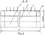
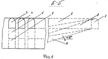
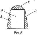
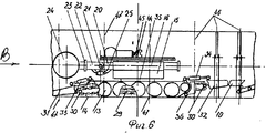
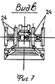
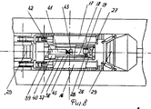
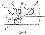
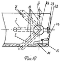
На фиг. 1 показан прямой ход комбайна в первом слое камеры; на фиг. 2 - обратный ход комбайна; на фиг. 3 - разрез А-А на фиг. 1; на фиг. 4 - разрез 5-5 на фиг. 1; на фиг. 5 - порядок отработки забоя исполнительным органом; на фиг. 6 - проходческий комбайн в продольном разрезе; на фиг 7 - вид спереди; на фиг. 8 - план; на фиг. 9 - положение исполнительного органа и бара при проходке и добыче; на фиг. 10 - положение бара при опережающем резе. In FIG. 1 shows the forward stroke of the combine in the first layer of the chamber; in FIG. 2 - return stroke of the combine; in FIG. 3 is a section AA in FIG. one; in FIG. 4 is a section 5-5 in FIG. one; in FIG. 5 - the procedure for mining the face by the executive body; in FIG. 6 - tunneling machine in longitudinal section; Fig. 7 is a front view; in FIG. 8 - plan; in FIG. 9 - the position of the executive body and the bar during sinking and production; in FIG. 10 - bar position with leading cut.
Способ разработки пластов полезного ископаемого предназначен для использования при камерной системе с блоковой подготовкой, включающей конвейерный 1 и вентиляционный 2 штреки, оконтуривающие выемочный участок, верхний слой (горизонт) 3 камер, имеющий арочное сечение, междукамерные целики 4, панельную выработку 5, камеры прямоугольного сечения второго 6 и третьего 7 слоя (горизонта), наклонную часть подготовительной выработки 8 при подготовке второго слоя (горизонт) 6 в камерах. The method of developing mineral strata is intended for use in a chamber system with block preparation, including conveyor 1 and
Отработка слоев (горизонтов) 3, 6, 7 в камерах и проходка штреков 1, 2 осуществляется проходческо-добычным универсальным комбайном (ПДКУ) 9 с перегрузкой горной массы на бункер-перегружатель 10 и в транспортное средство 11, например самоходные вагоны, с последующей перегрузкой на штрековую транспортную систему 12. The development of layers (horizons) 3, 6, 7 in the chambers and the passage of the
Проходческо-добычной комплекс состоит из комбайна 9, бункера-перегружателя 10 и транспортного средства 11 (фиг. 1, 2). Комбайн (фиг. 6, 7, 8) выполнен в виде гусеничного шасси 13 со смонтированной на корпусе полноповоротной в плоскости опирания 14 башней 15, на которой расположена левая 16 и правая 17 рукояти исполнительного органа, а также выдвигаемый бар 18 с приводом 19. Каждая из рукоятей 16 и 17 имеет выдвижные стрелы 20, состоящие из шарнирно (21) соединенных частей. Забойная часть стрелы 22 имеет механизм разворота 23 барабанов (шнеков) 24 вокруг продольной оси рукояти и гидроцилиндры 25, осуществляющие качающее движение барабанов (шнеков) 24 совместно с осями их крепления. Барабаны (шнеки) 24 имеют встроенный индивидуальный привод. The tunneling-mining complex consists of a
Выдвижной бар 18 установлен в направляющих балках 26 и имеет возможность выдвигаться на забой совместно с приводом 19 с помощью привода подачи 27, например в виде цевочного зацепления. Бар 18 с помощью гидроцилиндра (на чертеже не показан) имеет возможность совершать качающиеся движение вокруг оси 28 в плоскости, перпендикулярной плоскости почвы 14 и в направлении продольном оси комбайна. The
В корпусе комбайна 9 расположен изгибающийся скребковый конвейер 29, приводные звездочки 30 которого вынесены на симметричные, расположенные в передней и задней части комбайна, приемные столы 31 и 32, шарнирно (36) закрепленные на корпусе комбайна. Приемные столы 31 и 32 посредством гидроцилиндров соответственно 33 и 34 могут быть переведены из нижнего положения (под шнеком 24) в верхнее (в задней части комбайна). In the case of the
Башня 15 установлена на корпусе комбайна в поворотной опоре (погоне) 35 с приводом. Tower 15 is mounted on the housing of the combine in a rotary support (chase) 35 with a drive.
На корпусе комбайна 9 на опоре 35 над выдвижным баром 18 с приводом 19 и системой направляющих (выдвижных секций) 26 с приводом подачи 27 между рукоятями 16 и 17 располагается устройство для возведения временной и постоянной крепи, состоящее из платформы 37 с направляющими 38, в которых перемещается тележка 39 с помощью привода 40 с размещенной на ней телескопической рукоятью 41 и приводом 42, посредством которого рукоять 41 совершает качательные движения вокруг оси крепления к тележке 39. На конце рукояти 41 смонтирована каретка 43, имеющая возможность совершать качательные движения вокруг оси крепления 44 к рукояти 41 с помощью системы силовых гидроцилиндров 45. На каретке 43 предусмотрены устройства для размещения приспособления для анкерного крепления пород кровли (типа АК) и крепления выработок кассетной крепью 46 для постоянного крепления, располагаемой за комбайном и 47 для временного крепления, располагаемой над комбайном. On the housing of the
Способ разработки мощных, в том числе опасных по динамическим (газодинамическим) явлениям и с пластичными, неустойчивыми слоистыми кровлями, а также пучащими почвами, пластов полезного ископаемого реализуется с помощью проходческо-добычного комплекса, включающего комбайн (ПДКУ) 9 с выдвижным качающимся баром 18, бункер-перегружатель 10, транспортное средство 11. A method of developing powerful, including hazardous in dynamic (gas-dynamic) phenomena and with plastic, unstable layered roofs, as well as scattering soils, mineral strata is realized using a mining and production complex, including a combine harvester (MPC) 9 with a sliding swinging
При этом параметры выемочного участка определяются по формуле, позволяющей выбрать рациональные и безопасные условия ведения очистных работ:
Пв.уч.≤ (T•aуст•vk)/η (м2),
где Пв. уч. - площадь выемочного участка, м2;
T - время отработки пласта, сут;
ауст - показатель устойчивости комплекса "кровля-целик", м;
η - количество отрабатываемых горизонтов;
Vk - скорость проходки, м/сут.In this case, the parameters of the excavation site are determined by the formula, which allows you to choose rational and safe conditions for the treatment:
P v.uch. ≤ (T • a mouth • v k ) / η (m 2 ),
where P c. student - the area of the excavation site, m 2 ;
T is the time of development of the reservoir, days;
and mouth - an indicator of the stability of the complex "roof-rear", m;
η is the number of horizons worked out;
V k - penetration rate, m / day.
Вентиляционный 2 и конвейерный 1 штреки для нарезки блока (фиг. 1) и отработки первого слоя (горизонта) 3 камер проходятся комбайном 9 с панельной выработки 5. В случае работы на опасных по ДЯ пластах перед началом отработки забоя барабаном (шнеком) 24 производится опережающий рез баром 18, при этом снижается напряженное состояние массива, работы при этом ведутся в следующем порядке. Комбайн 9 устанавливается по центру выработки, максимально придвинутый к забою, шнеки 24 стрел 20 гидроцилиндрами 25 удерживаются в горизонтальном положении (положение 1 фиг. 9), а сами стрелы 20 находятся в максимально вдвинутом положении относительно рукоятей 16 и 17 так, что шнеки 24 упираются в забой. Посредством привода подачи 27 бар 18 в направляющих балках 26 выдвигается на забой, при этом режущая цепь приводится в движение приводом 19. Консольно выдвинутый бар 18, заглубленный на полную длину (положение I на фиг. 10), посредством гидроцидиндра начинает осуществлять круговой рез, перемещаясь относительно шарнира 28, поднимаясь до тех пор, пока высота реза превысит высоту выработки (положение II фиг. 10). Затем, бар 18 опускается в рабочем режиме до положения, когда начинает разрушаться почва (положение III фиг. 10), после этого бар 18 переводится в горизонтальное положение и перемещается в нерабочее (транспортное) положение приводом 27.
Выемка породы (угля) в забое осуществляется по различным схемам, зависящим от вида сечения выработки. The extraction of rock (coal) in the face is carried out according to various schemes, depending on the type of cross-section of the mine.
При проходке выработок (камер) по полезному ископаемому с f < 4 квадратного сечения (зона "0" на фиг. 5) отбойка производится только с помощью гидроцилиндра 25 в вертикальной плоскости, гидроцилиндрами телескопического выдвижения стрел 20, а отбойка целиков, оставшихся между барабанами (шнеками), производится поворотом башни 15 с помощью механизма поворотного круга 35. When excavating workings (chambers) along a mineral with f <4 square sections (zone "0" in Fig. 5), breaking is carried out only with the help of
При проходке выработок по породе с f < 4, сечение которых отличается от трапециевидного или прямоугольного, необходимо выполнить дополнительные движения исполнительным органом по отбойке зон "Л, К, П" (фиг. 5). Для отбойки породы в правой части зоны "К" (фиг. 5) барабаны (шнеки) 24 с помощью стрелы 20 рукояти 17 с помощью гидроцилиндров телескопического действия выводятся из контакта с забоем, барабаны (шнеки) 24 поворачиваются вокруг продольной оси стрелы 20 механизмом 23, затем отрабатывается зона "К" с использованием гидроцилиндров телескопического выдвижения, цилиндров качания стрелы 25 и механизма поворотного круга 35. В это время стрела 20 рукояти 18 втянута во внутрь последней и опущена. Левая часть зоны "К" (фиг. 5) отрабатывается рукоятью 16. Зона "П" (фиг. 5) отрабатывается правой рукоятью 17 при втянутой стреле 20 в левую рукоять 16, забойная часть 22 которой находится в горизонтальном положении. When driving workings through the breed with f <4, the cross section of which differs from the trapezoidal or rectangular, it is necessary to perform additional movements by the executive body to break the zones "L, K, P" (Fig. 5). To break the rock in the right part of the zone "K" (Fig. 5), the drums (screws) 24 using the
Отбитая порода попадает на приемный стол 31 (опущенный) и транспортируется конвейером 29 в заднюю часть комбайна 9, где поступает на приемный стол 32 (поднятый). Далее грузопоток проходит бункер-перегружатель 10 и попадает в транспортное средство 11. The broken rock enters the receiving table 31 (lowered) and is transported by a
Крепление проводимых выработок осуществляется с помощью устройства для возведения временной и постоянной кассетной крепи. Возведение временной крепи осуществляется следующим образом: тележка 39 по направляющим 38 платформы 37 перемещается в направлении приемного стола 32, находящегося в верхнем положении, при этом телескопическая рукоять 41 находится в горизонтальном положении и выдвинута на необходимую длину в направлении приемного стола 32. На каретку 43 помещается верхняя секция арочной крепи и тележка 39 по направляющим 38 платформы 37 перемещается в направлении приемного стола 31, находящегося в нижнем положении, при этом телескопическая рукоять 41 поворачивается вокруг оси крепления к тележке 39 в том же направлении, каретка 43 с верхней секцией крепи прижимается к кровле выработки за барабанами (шнеками) 24 и удерживается в этом положении, пока не будут смонтированы боковые стойки крепи. Постоянная кассетная крепь аналогичным образом возводится за комбайном 9 . Анкерная крепь возводится с помощью приспособления для анкерной крепи, монтируемого на каретке 43 с помощью специального устройства. Mounting of the workings is carried out using a device for the construction of temporary and permanent cassette lining. The construction of the temporary lining is carried out as follows: the trolley 39 along the guides 38 of the platform 37 moves in the direction of the receiving table 32, which is in the upper position, while the
Добычные работы в слоях (горизонтах) 3 (6, 7) камер ведутся аналогично проходке камер 1, 2, при этом при проходке первого слоя (горизонта) 3 камер арочного сечения производится анкерное крепление кровли. Mining operations in layers (horizons) of 3 (6, 7) chambers are carried out similarly to the passage of
При добычных работах в присечку в камерах слоя (горизонта) (фиг. 1, 2), комбайн 9 не имеет холостых перегонов. После выхода на штрек 2 барабаны (шнеки) 24 гидроцилиндрами 25 приводятся в положение IV (фиг. 9), башня 15 комбайна 9 разворачивается на 180o, приемный стол 31 из нижнего положения переводится в верхнее, а стол 32 - из верхнего в нижнее, шнеки 24 переводятся в рабочее положение 1, 11 (фиг. 9), осуществляется зарубка и работа по добыче в присечку.During mining operations in the notch in the chambers of the layer (horizon) (Fig. 1, 2), the
После окончания добычных работ по отработке камер первого слоя (горизонта) 3 камер во всем участке, комбайн 9 перегоняется по штреку 1(2) на панельную выработку 5 и производит проходку наклонной части 8 выработки 1(2) для подготовки блока и отработки камер второго слоя 6 (прямоугольного сечения) (фиг. 3, 4). При этом комбайн 9 осуществляет подрывку почвы в выработке 8 с помощью барабанов (шнеков) 24, опущенных в положение 11 (фиг. 9) при предельно выдвинутых стрелах 20 относительно рукоятей 16, 17. Отработка (подрывка) почвы 14 (фиг. 1, 4, 9, 10) производится комбайном 9 при последовательном увеличении глубины подрывки на расстояние от выработки 5 до блока таким образом, что при подходе к блоку (фиг. 4) высота слоя 6 камер должна быть в пределах 3 - 4 м. Угол заглубления (падения) штреков 1, 2 в их частях 8 не должен превышать 18o по условию нормальной работы конвейерного транспорта 12. Далее комбайн 9 осуществляет отработку слоя (горизонта) 6 во всех камерах в пределах выемочного участка. Аналогично производится подготовка следующего горизонта выемочного участка к добыче и собственно добыча при заглублении на слой (горизонт) 7 камер выемочного участка и более нижних слоев (горизонтов) при выемке пласта на всю мощность.After the completion of mining operations to develop the chambers of the first layer (horizon) of 3 chambers in the entire section, the
При ведении добычных работ в выработках с пучащими почвами их подрывка осуществляется комбайном 9 при установке шнеков в положение 11 (фиг. 9). When conducting mining operations in workings with sweeping soils, their undermining is carried out by the
Отличительные признаки изобретения позволяют повысить эффективность отработки мощных пластов за счет повышения концентрации горных работ, а также обеспечить высокую эффективность и безопасность выработок на пластовых месторождениях по пластам, опасным по динамическим явлениям (удары, выбросы), при наличии неустойчивых слоистых, пластинчатых пород в кровле и пучащих почв за счет использования проходческо-добычного комбайна (ПДКУ) с универсальным исполнительным органом, активно воздействующим на геомеханические параметры призабойного массива и формирующим выработки с необходимой конфигурацией сечений. Distinctive features of the invention can improve the efficiency of mining powerful formations by increasing the concentration of mining, as well as ensure high efficiency and safety of workings in reservoir deposits in formations that are dangerous in dynamic phenomena (impacts, emissions), in the presence of unstable layered, lamellar rocks in the roof and sowing soils through the use of a tunneling-mining combine (MPCU) with a universal executive body that actively affects geomechanical parameters bottom-hole on the array and forms a generation with the necessary configuration sections.
Claims (5)
Пв . у ч ≤ (Т • ау с т • vк)/n,
где Пв . у ч площадь выемочного участка, м2;
Т время отработки пласта, сутки;
ауст показатель устойчивости комплекса кровля целик, м;
n количество отрабатываемых горизонтов;
vк скорость проходки, м/сутки.2. The method according to p. 1, characterized in that the parameters of the excavation section is determined from the expression
P in. y h ≤ (T • a y s t • v k ) / n,
where P c . y h excavation site area, m 2;
T the time of development of the reservoir, day;
and mouth is an indicator of the stability of the whole roof complex, m;
n number of horizons worked out;
v to the speed of penetration, m / day.
Priority Applications (1)
| Application Number | Priority Date | Filing Date | Title |
|---|---|---|---|
| RU96114000A RU2103507C1 (en) | 1996-07-15 | 1996-07-15 | Method and cutter-loader machine for development of seam deposits of minerals |
Applications Claiming Priority (1)
| Application Number | Priority Date | Filing Date | Title |
|---|---|---|---|
| RU96114000A RU2103507C1 (en) | 1996-07-15 | 1996-07-15 | Method and cutter-loader machine for development of seam deposits of minerals |
Publications (2)
| Publication Number | Publication Date |
|---|---|
| RU96114000A RU96114000A (en) | 1998-01-27 |
| RU2103507C1 true RU2103507C1 (en) | 1998-01-27 |
Family
ID=20183111
Family Applications (1)
| Application Number | Title | Priority Date | Filing Date |
|---|---|---|---|
| RU96114000A RU2103507C1 (en) | 1996-07-15 | 1996-07-15 | Method and cutter-loader machine for development of seam deposits of minerals |
Country Status (1)
| Country | Link |
|---|---|
| RU (1) | RU2103507C1 (en) |
Cited By (6)
| Publication number | Priority date | Publication date | Assignee | Title |
|---|---|---|---|---|
| EA014034B1 (en) * | 2008-07-29 | 2010-08-30 | Открытое Акционерное Общество "Белгорхимпром" (Оао "Белгорхимпром") | Excavation method of minerals seam |
| RU2490454C1 (en) * | 2012-03-11 | 2013-08-20 | Федеральное государственное бюджетное учреждение науки Институт угля Сибирского отделения Российской академии наук (ИУ СО РАН) | Method for open-underground mining of thick steep coal bed |
| RU2555997C1 (en) * | 2014-06-24 | 2015-07-10 | Федеральное государственное бюджетное учреждение науки Институт угля Сибирского отделения Российской академии наук (ИУ СО РАН) | Method of open-underground development of thick single steeply inclined coal seam |
| RU2651833C1 (en) * | 2017-03-29 | 2018-04-24 | Федеральное государственное бюджетное научное учреждение "Федеральный исследовательский центр угля и углехимии Сибирского отделения Российской академии наук (ФИЦ УУХ СО РАН) | Method of open-underground development of coal bed, lying in the form of brachysyncline |
| CN108035715A (en) * | 2017-12-27 | 2018-05-15 | 山东科技大学 | A kind of unregulated fully mechanized coal mining face just adopts stage isometric tune face method |
| CN118187848A (en) * | 2024-04-18 | 2024-06-14 | 陕煤集团神木张家峁矿业有限公司 | Ore layer cutting off device for coal mine exploitation |
-
1996
- 1996-07-15 RU RU96114000A patent/RU2103507C1/en active
Cited By (7)
| Publication number | Priority date | Publication date | Assignee | Title |
|---|---|---|---|---|
| EA014034B1 (en) * | 2008-07-29 | 2010-08-30 | Открытое Акционерное Общество "Белгорхимпром" (Оао "Белгорхимпром") | Excavation method of minerals seam |
| RU2490454C1 (en) * | 2012-03-11 | 2013-08-20 | Федеральное государственное бюджетное учреждение науки Институт угля Сибирского отделения Российской академии наук (ИУ СО РАН) | Method for open-underground mining of thick steep coal bed |
| RU2555997C1 (en) * | 2014-06-24 | 2015-07-10 | Федеральное государственное бюджетное учреждение науки Институт угля Сибирского отделения Российской академии наук (ИУ СО РАН) | Method of open-underground development of thick single steeply inclined coal seam |
| RU2651833C1 (en) * | 2017-03-29 | 2018-04-24 | Федеральное государственное бюджетное научное учреждение "Федеральный исследовательский центр угля и углехимии Сибирского отделения Российской академии наук (ФИЦ УУХ СО РАН) | Method of open-underground development of coal bed, lying in the form of brachysyncline |
| CN108035715A (en) * | 2017-12-27 | 2018-05-15 | 山东科技大学 | A kind of unregulated fully mechanized coal mining face just adopts stage isometric tune face method |
| CN108035715B (en) * | 2017-12-27 | 2019-05-07 | 山东科技大学 | A kind of unregulated fully mechanized coal mining face just adopts stage isometric tune face method |
| CN118187848A (en) * | 2024-04-18 | 2024-06-14 | 陕煤集团神木张家峁矿业有限公司 | Ore layer cutting off device for coal mine exploitation |
Similar Documents
| Publication | Publication Date | Title |
|---|---|---|
| US8317430B2 (en) | Crawler-type and height adjustment drilling machine for setting roof and side wall anchor bolts and anchor cables | |
| KR100209103B1 (en) | Excavator for forming underground continuous wall | |
| US4014574A (en) | Mining machine having rectangular thrust transmitting conveyor column | |
| CN101881162B (en) | Drill loader | |
| CN101169036B (en) | Pedrail type lifting top slope anchor shaft anchor cable construction drilling machine and single-alley fast tunneling technique | |
| CN101403302B (en) | Pedrail type liftable anchor bar anchor cable construction drill rig and double-lane fast digging technique | |
| CN102213094B (en) | Construction system and construction method for mine rock drivage | |
| RU2344291C2 (en) | System of deposit development | |
| CN103742176A (en) | Excavating and anchor-supporting all-in-one unit | |
| CN109538224A (en) | A kind of novel coal lane high-speed driving machine | |
| CN107191191A (en) | A kind of rock gangway fast digging technique of the breaking rock gangway anchor driving machine of three hammering blows | |
| CN201401166Y (en) | Drill loader | |
| CN101781972B (en) | Crawler-type lifting top and slope bolt and anchor construction drill | |
| CN114718588A (en) | Four-stage sliding cutting type four-wheel drive combined device for digging, supporting, anchoring and transporting and working method | |
| CN101302932A (en) | Method for underground chamber digging and laneway opening digging | |
| RU2103507C1 (en) | Method and cutter-loader machine for development of seam deposits of minerals | |
| CN102383795B (en) | Comprehensive mechanical rock drift excavating process | |
| CN102425415A (en) | Gangue racking machine for half-coal rock roadway blasting driving | |
| AU2004216593B2 (en) | Combination panline and utility drilling or bolting unit | |
| CN209494569U (en) | A kind of novel coal lane high-speed driving machine | |
| CN115929368B (en) | Anchor rod transfer unit suitable for arch roadway, combined device and construction method | |
| USRE31622E (en) | Mining machine having rectangular thrust transmitting conveyor column | |
| Okubo et al. | Underground mining methods and equipment | |
| RU2295037C1 (en) | Method for extracting thick inclined coal formation by column-chambers | |
| RU2302529C1 (en) | Complex for tunnel excavation in weak ground |