CN114718588A - Four-stage sliding cutting type four-wheel drive combined device for digging, supporting, anchoring and transporting and working method - Google Patents
Four-stage sliding cutting type four-wheel drive combined device for digging, supporting, anchoring and transporting and working method Download PDFInfo
- Publication number
- CN114718588A CN114718588A CN202210260074.3A CN202210260074A CN114718588A CN 114718588 A CN114718588 A CN 114718588A CN 202210260074 A CN202210260074 A CN 202210260074A CN 114718588 A CN114718588 A CN 114718588A
- Authority
- CN
- China
- Prior art keywords
- supporting
- anchoring
- tunneling
- frame
- main
- Prior art date
- Legal status (The legal status is an assumption and is not a legal conclusion. Google has not performed a legal analysis and makes no representation as to the accuracy of the status listed.)
- Pending
Links
Images


Classifications
-
- E—FIXED CONSTRUCTIONS
- E21—EARTH DRILLING; MINING
- E21D—SHAFTS; TUNNELS; GALLERIES; LARGE UNDERGROUND CHAMBERS
- E21D9/00—Tunnels or galleries, with or without linings; Methods or apparatus for making thereof; Layout of tunnels or galleries
- E21D9/10—Making by using boring or cutting machines
- E21D9/1006—Making by using boring or cutting machines with rotary cutting tools
-
- E—FIXED CONSTRUCTIONS
- E21—EARTH DRILLING; MINING
- E21D—SHAFTS; TUNNELS; GALLERIES; LARGE UNDERGROUND CHAMBERS
- E21D20/00—Setting anchoring-bolts
- E21D20/003—Machines for drilling anchor holes and setting anchor bolts
-
- E—FIXED CONSTRUCTIONS
- E21—EARTH DRILLING; MINING
- E21D—SHAFTS; TUNNELS; GALLERIES; LARGE UNDERGROUND CHAMBERS
- E21D23/00—Mine roof supports for step- by- step movement, e.g. in combination with provisions for shifting of conveyors, mining machines, or guides therefor
- E21D23/04—Structural features of the supporting construction, e.g. linking members between adjacent frames or sets of props; Means for counteracting lateral sliding on inclined floor
-
- E—FIXED CONSTRUCTIONS
- E21—EARTH DRILLING; MINING
- E21D—SHAFTS; TUNNELS; GALLERIES; LARGE UNDERGROUND CHAMBERS
- E21D23/00—Mine roof supports for step- by- step movement, e.g. in combination with provisions for shifting of conveyors, mining machines, or guides therefor
- E21D23/08—Advancing mechanisms
-
- E—FIXED CONSTRUCTIONS
- E21—EARTH DRILLING; MINING
- E21D—SHAFTS; TUNNELS; GALLERIES; LARGE UNDERGROUND CHAMBERS
- E21D9/00—Tunnels or galleries, with or without linings; Methods or apparatus for making thereof; Layout of tunnels or galleries
- E21D9/10—Making by using boring or cutting machines
- E21D9/1086—Drives or transmissions specially adapted therefor
-
- E—FIXED CONSTRUCTIONS
- E21—EARTH DRILLING; MINING
- E21D—SHAFTS; TUNNELS; GALLERIES; LARGE UNDERGROUND CHAMBERS
- E21D9/00—Tunnels or galleries, with or without linings; Methods or apparatus for making thereof; Layout of tunnels or galleries
- E21D9/10—Making by using boring or cutting machines
- E21D9/1093—Devices for supporting, advancing or orientating the machine or the tool-carrier
-
- E—FIXED CONSTRUCTIONS
- E21—EARTH DRILLING; MINING
- E21D—SHAFTS; TUNNELS; GALLERIES; LARGE UNDERGROUND CHAMBERS
- E21D9/00—Tunnels or galleries, with or without linings; Methods or apparatus for making thereof; Layout of tunnels or galleries
- E21D9/10—Making by using boring or cutting machines
- E21D9/11—Making by using boring or cutting machines with a rotary drilling-head cutting simultaneously the whole cross-section, i.e. full-face machines
- E21D9/112—Making by using boring or cutting machines with a rotary drilling-head cutting simultaneously the whole cross-section, i.e. full-face machines by means of one single rotary head or of concentric rotary heads
-
- E—FIXED CONSTRUCTIONS
- E21—EARTH DRILLING; MINING
- E21D—SHAFTS; TUNNELS; GALLERIES; LARGE UNDERGROUND CHAMBERS
- E21D9/00—Tunnels or galleries, with or without linings; Methods or apparatus for making thereof; Layout of tunnels or galleries
- E21D9/12—Devices for removing or hauling away excavated material or spoil; Working or loading platforms
- E21D9/126—Loading devices or installations
Abstract
The invention discloses a four-stage sliding cutting type tunneling, supporting, anchoring and transporting four-wheel drive combined device and a working method, wherein the device comprises a tunneling mechanism, an anchoring mechanism and a supporting mechanism, the tunneling mechanism can realize four-stage sliding, and full-face cutting can be realized under the condition that a tunneling host is not moved; the full-section shovel plate can realize the functions of overturning, stretching, small star wheel auxiliary operation and the like, and can realize full-section shoveling operation; the front section and the rear section of the tunneling mechanism are driven to travel in four directions, so that the actions of rotation, torsion, pitching and the like can be realized, and the tunneling mechanism has high horsepower and strong climbing capability. The supporting mechanism can realize the operation of leaving the machine with the tunneling main machine, and the effect of supporting the top plate and the side wall of the roadway without repeated rolling is achieved. The anchoring mechanism is treated in a modularized way, so that rapid assembly and separation can be realized; the anchoring mechanism can realize multi-process operation of top anchoring, side anchoring and anchor rope, has the function of mechanically feeding steel strips, and can effectively improve the anchoring efficiency.
Description
Technical Field
The invention relates to the technical field of coal mine roadway rapid tunneling equipment, in particular to a four-stage sliding cutting type tunneling, support, anchoring and transportation four-wheel drive combined device and a working method.
Background
The problems of small space, multiple processes, complex system, poor geological condition and the like of the underground driving face of the coal mine lead the intelligent development of the driving face to be seriously lagged behind the coal face, thereby greatly reducing the coal mining efficiency.
To realize intensive, personnel-reduced, rapid, efficient and safe construction of a fully-mechanized excavation working face, workers must be far away from a severe operation environment to ensure that the workers operate under a safe roof, and the existing excavation equipment cannot be safe and efficient at the same time and is difficult to adapt to complex geological conditions.
The chinese patent with patent number 201910245399.2 proposes a fast tunneling system and a fast tunneling method, before a tunneling device cuts, a temporary support device is firstly adopted to temporarily support a roadway to ensure the safety of roadway construction, after a cutting assembly cuts for a preset time, a support assembly jacks up at least one support, the support is switched from a support state to a retraction state, and the support assembly drives the support to move to a preset position. Meanwhile, the supporting device supports the anchor rod and/or the anchor cable of the roadway. The support transported to the preset position is switched to a supporting state from a retraction state to support the roadway, so that the temporary supporting device moves forwards, and the tunneling device continues to perform cutting operation. The patent realizes that the tunneling action of the tunneling device and the supporting operation of the supporting device are carried out simultaneously, but still has the following defects:
1. the tunneling mechanism can only excavate towards the tunneling direction, and the coal bed can be cut only by moving the whole device to move forwards and backwards, so that the device is inconvenient to use;
2. the actions of rotation, torsion, pitching and the like can not be realized before and after the tunneling mechanism, and the tunneling mechanism is difficult to adapt to complex working condition conditions;
3. the transportation mechanism is difficult to collect the collected coal slag, and the working efficiency of the whole device is influenced;
4. the anchoring mechanism is not designed in a modularized mode, cannot be used independently and is poor in flexibility.
In order to overcome the defects of the prior art, a four-stage sliding cutting type excavating, supporting, anchoring and transporting four-wheel drive combined device and a working method thereof are urgently needed.
Disclosure of Invention
The invention provides a four-stage sliding cutting type excavating, supporting, anchoring and transporting four-wheel drive combined device and a working method aiming at the defects of the prior art, the device and the method realize the simultaneous tunneling and supporting, a tunneling mechanism can realize four-stage sliding, full-section cutting is realized in the state that the device is not moved, and in addition, a full-section shovel plate can realize the functions of turning, stretching, small star wheel auxiliary operation and the like, so that full-section shoveling and transporting can be realized; the front section and the rear section of the tunneling mechanism can realize actions such as rotation, torsion, pitching and the like, and are suitable for complex working conditions.
In order to solve the technical problems, the invention adopts the technical scheme that:
a four-stage sliding cutting type tunneling, supporting, anchoring and transporting four-wheel drive combined device comprises a supporting mechanism, an anchoring mechanism and a tunneling mechanism.
The fast tunneling direction in the roadway is defined as an X-axis direction, the main supporting direction of the supporting mechanism is a Z-axis direction, and the side wall supporting direction of the supporting mechanism is a Y-axis direction.
The tunneling mechanism comprises a tunneling mechanism front section, a three-degree-of-freedom cutting platform, a telescopic cutting head, a multiple-degree-of-freedom connecting mechanism, a tunneling mechanism rear section and a scraper conveyor.
The front section of the tunneling mechanism comprises a front travelling mechanism, a main frame and a full-section shovel plate.
The front walking mechanism is a crawler-type walking device; the top of the front walking mechanism is fixed with a main frame; the full-section shovel plate is hinged with the main frame, and the rotating direction of the full-section shovel plate is that the plane where the X axis and the Y axis are located rotates towards the plane where the Y axis and the Z axis are located.
A three-degree-of-freedom cutting platform is fixed at the top of the main frame; the three-degree-of-freedom cutting platform comprises an X axial pushing platform, an X axial guiding device, a Y axial pushing platform, a Y axial guiding device, a rotary platform and a rotary device.
The X axial pushing platform and the X axial guiding device form an X axial moving sliding pair which relatively slides in the X axial direction; the Y-axis pushing platform and the Y-axis guiding device form a sliding pair moving in the Y-axis direction and relatively slide in the Y-axis direction; the rotary platform and the rotary device form a hinge pair which can rotate 360 degrees on a plane formed by an X axis and a Y axis.
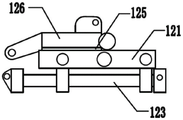
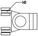
The top of the three-degree-of-freedom cutting platform is fixedly provided with a telescopic cutting head; the telescopic cutting head is used for cutting a coal wall during rapid tunneling; the multi-degree-of-freedom connecting mechanism comprises a torsion joint, a rotary joint and a pitching joint; the torsional joint provides a rotational degree of freedom in the X-axis direction; the rotary joint provides a rotational degree of freedom in the Y-axis direction; the pitch joint provides rotational freedom in the Z-axis direction.
The back section of the tunneling mechanism comprises a back travelling mechanism, a back frame and a power device.
The rear travelling mechanism is a crawler-type travelling device; the top of the rear walking mechanism is fixed with a rear frame; a power device is fixed on the rear frame and provides walking power for the rear walking mechanism; and a trailing rod is also fixed on the rear frame.
The scraper conveyor is fixed on the top of the rear frame and connected with the full-section shovel plate.
The anchoring mechanism comprises an anchoring base, an anchoring rack, a groove seat, a top anchor rod drilling machine and a side anchor rod drilling machine.
The bottom of the anchoring base is provided with a sliding shoe, and the anchoring base slides on the ground through the sliding shoe; the top of the anchoring base is fixed with a groove seat which is clamped with a dragging rod on the rear frame to connect the anchoring base with the rear frame.
An anchoring rack is vertically fixed at the top of the anchoring base; a top anchor rod drilling machine and a side anchor rod drilling machine are fixed on the anchoring rack; the top anchor rod drilling machine nails an anchor rod into the top of the roadway along the Z-axis direction; and the side anchor rod drilling machine nails the anchor rods into two side walls of the roadway along the Y-axis direction.
The supporting mechanism comprises a main supporting frame, an auxiliary supporting frame, a constraint track, a supporting mechanism walking motor, a circulating supporting top plate and a side wall support.
The main supporting frame comprises two main supporting support rods and a main supporting cross beam connected with the two main supporting support rods; the main supporting struts are vertically arranged, the bottom of each main supporting strut is provided with a walking crawler belt, and the main supporting framework can freely move under the driving of a walking motor of the supporting mechanism.
The auxiliary supporting frame and the main supporting frame are arranged in parallel; the auxiliary supporting frame comprises two auxiliary supporting struts and an auxiliary supporting cross beam for connecting the two auxiliary supporting struts; the bottom of the auxiliary supporting strut is provided with a sliding shoe, and the auxiliary supporting framework slides on the ground through the sliding shoe.
The main supporting frame is matched with the auxiliary supporting frame through the constraint track, the constraint track constrains the main supporting frame and the auxiliary supporting frame to only generate displacement in the X-axis direction, and no relative displacement exists in the Y-axis direction and the Z-axis direction.
The auxiliary supporting frame is sleeved outside the main supporting frame, and the main supporting frame is sleeved on the front section of the tunneling mechanism to provide support for the tunneling mechanism.
The main supporting rod and the auxiliary supporting rod are both provided with telescopic cylinders, and the main supporting rod and the auxiliary supporting rod are driven to stretch in the Z-axis direction.
And the circulating support top plate is fixed at the top ends of the main support cross beam and the auxiliary support cross beam and is used for supporting the top surface of the roadway.
The side wall support is vertically fixed on the side wall of the auxiliary support supporting rod facing the roadway and used for supporting the two side wall surfaces of the roadway.
Further preferably, the full-face shovel plate comprises a main shovel plate, a main star wheel and a side shovel plate; the main shovel plate is hinged with the main frame, and the main shovel plate takes the Y-axis direction as a rotating shaft to realize pitching rotation; a main star wheel is arranged on the main shovel plate and used for scraping coal in a rotating mode and conveying the coal cut by the telescopic cutting head into a scraper conveyor; the side shovel plate is hinged with the main shovel plate, and the side shovel plate uses the X axis as a rotating shaft to realize pitching rotation.
Further preferably, the full-section shovel plate further comprises a telescopic shovel plate, an auxiliary shovel plate and an auxiliary star wheel; the telescopic shovel plate is connected with the side shovel plate through a built-in oil cylinder and can be expanded in a Y-axis direction in a telescopic mode; an auxiliary star wheel is fixed on the telescopic shovel plate; the auxiliary star wheel continuously rotates to enable the coal on the full-section shovel plate to be in a floating state all the time; the auxiliary shovel plate is in threaded connection with the telescopic shovel plate and can be flexibly detached.
Further preferably, the anchoring mechanism further comprises a cable drill; the anchor cable drilling machine is fixed on the anchoring rack along the X-axis direction and the Y-axis direction respectively; and the anchor cable drilling machine nails the anchor cable into the top of the roadway and two side walls of the roadway.
Further preferably, the anchoring mechanism further comprises a steel belt feeding device; the steel belt feeding device is fixed on the anchoring rack;
the steel belt feeding device comprises a fixing frame, a chain wheel set, a steel belt support frame, a ratchet wheel, a main pawl, an auxiliary pawl, a hand lever, a steel belt tray and a pushing oil cylinder;
the fixed frame is horizontally fixed on the anchoring rack; the chain wheel set is vertically arranged on the fixing frame and comprises an upper chain wheel and a lower chain wheel which are connected through a chain; the chain is provided with a steel belt support frame for placing a steel belt; the ratchet wheel is connected with the chain wheel set in a matched manner through a flat key; the hand-operated lever is hinged with the anchoring rack through a pin shaft; the main pawl and the auxiliary pawl are respectively hinged with the hand-operated rod, the hand-operated rod is toggled to drive the ratchet wheel to rotate, the ratchet wheel rotates to drive the chain wheel set to rotate, the chain wheel set rotates to drive the steel belt strut to descend, and the steel belt strut falls into the steel belt tray arranged on the fixed frame; the bottom of the steel belt tray is provided with a roller which is pushed by the pushing oil cylinder to move to the upper part of the top anchor rod drilling machine, and the top anchor rod drilling machine drives the steel belt into a roadway to finish the steel belt arrangement operation.
Preferably, the side faces, facing the roadway, of the secondary supporting struts are all provided with side wall supports, each secondary supporting strut is provided with two groups of side wall supports, and the two groups of side wall supports are arranged in a staggered manner.
A working method of a four-stage sliding cutting type excavating, supporting, anchoring and transporting four-wheel drive combined device specifically comprises the following steps:
s1, covering the front section of the tunneling mechanism by a supporting mechanism, and fixing an anchoring mechanism at the rear section of the tunneling mechanism; a telescopic cutting head of the tunneling mechanism and the three-degree-of-freedom cutting platform are cooperatively controlled to cut the section of the front end of the roadway into a preset depth according to a preset contour; the three-degree-of-freedom cutting platform can enable the telescopic cutting head to have moving degrees of freedom in the directions of an X axis, a Y axis and a Z axis;
s2, loading the coal cinder materials accumulated on the ground onto a scraper conveyor by a full-section shovel plate, and transporting the coal cinder materials to a designated position backwards;
s3, in the tunneling process of the tunneling device, a top anchor rod drilling machine, a side anchor rod drilling machine and an anchor cable drilling machine of the anchoring mechanism work simultaneously, an anchor rod and an anchor cable are nailed into the coal wall of the roadway, and the roadway top wall and the roadway side wall around the anchoring mechanism are permanently supported;
s4, synchronously starting a steel belt feeding device, and providing steel belts for a top anchor rod drilling machine, a side anchor rod drilling machine and an anchor cable drilling machine when the top anchor rod drilling machine, the side anchor rod drilling machine and the anchor cable drilling machine work;
s5, the supporting mechanism and the top wall of the roadway are always in stable contact and supporting relation, and after S2-S4 is completed, the front section of the tunneling mechanism and the rear section of the tunneling mechanism simultaneously drive forwards to a preset position; the main supporting frame of the supporting mechanism contracts and separates from the circulating supporting top plate, and after the main supporting frame travels a preset distance in the tunneling direction, the main supporting frame extends again and supports the circulating supporting top plate; then the auxiliary supporting frame contracts to separate from the circulating supporting top plate, slides in the forward tunneling direction under the traction of the constraint track, and extends out and supports the circulating supporting top plate again after the auxiliary supporting frame travels the same distance with the main supporting frame;
s6, the anchoring mechanism is clamped with the rear frame through the dragging rod; after the rear section of the tunneling mechanism moves towards the tunneling direction, the anchoring mechanism is dragged to move and keeps still relative to the tunneling mechanism;
s7, when the bottom surface of the roadway is uneven, the multi-degree-of-freedom connecting mechanism enables the relative position of the front section of the tunneling mechanism and the rear section of the tunneling mechanism to change along with the terrain, and the good ground contact effect of the whole machine is ensured.
The invention has the following beneficial effects:
1. the tunneling device can realize four-stage sliding, and comprises a tunneling host machine, a rotary table, a cutting part and a driving mechanism, wherein the tunneling host machine travels forwards and backwards, the rotary table slides leftwards and rightwards, and the cutting part stretches out and draws back, so that full-section cutting is realized under the combined action of the tunneling host machine and the cutting part under the immovable state of the machine body;
2. the full-section shovel plate can realize the functions of overturning, stretching, small star wheel auxiliary operation and the like, and can realize full-section shoveling;
3. the front section and the rear section of the tunneling mechanism are driven to travel in four directions, so that the actions of rotation, torsion, pitching and the like can be realized, the high-horsepower and strong climbing capability is realized, and the high-power tunneling mechanism can adapt to complex working conditions;
4. the modular design of the anchoring system can be realized, the system can be used independently, and can also be quickly connected and installed for integral anchoring operation; the steel band loading device can realize the mechanized installation of steel bands.
Drawings
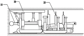
FIG. 1 is a schematic view of the connection of the whole structure of a four-stage slipping cutting type digging, supporting, anchoring and transporting four-wheel drive combined device of the invention.
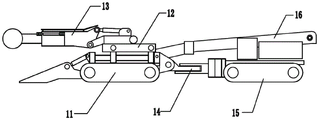
Fig. 2 is a schematic diagram of a tunneling mechanism of a four-stage slipping cutting type tunneling, support, anchoring and four-wheel drive combined device.
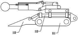
Fig. 3 is a front schematic view of a tunneling mechanism of a four-stage slipping cutting type tunneling, support, anchoring and four-wheel drive combined device.
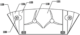
FIG. 4 is a schematic structural view of a full-section shovel plate of the four-stage slipping cutting type tunneling, support, anchoring and transporting combined device of the invention.
Fig. 5 is a top view of a three-degree-of-freedom cutting platform of a four-stage sliding cutting type digging, supporting, anchoring and transporting four-wheel drive combined device.
Fig. 6 is a front view of a three-degree-of-freedom cutting platform of a four-stage sliding cutting type digging, supporting, anchoring and transporting four-wheel drive combined device.
FIG. 7 is a front view of a multi-degree-of-freedom connecting mechanism of the four-stage slipping cutting type tunneling, support, anchoring and transporting combined device.
FIG. 8 is a top view of the multi-degree-of-freedom connecting mechanism of the four-stage slipping cutting type tunneling, support, anchoring and transporting four-wheel drive combined device of the invention.
Fig. 9 is a schematic structural diagram of a rear section of a tunneling mechanism of the four-stage slipping cutting type tunneling, support, anchoring and four-wheel drive combined device.
Fig. 10 is a schematic structural diagram of an anchoring mechanism of a four-stage slipping cutting type excavating, supporting, anchoring and transporting four-wheel drive combined device.
FIG. 11 is a schematic structural diagram of an upper steel belt device of a four-stage slipping cutting type digging, supporting, anchoring and transporting four-wheel drive combined device.
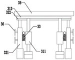
Fig. 12 is a front view of the supporting mechanism of the four-stage slipping cutting type excavating, supporting, anchoring and transporting four-wheel drive combined device.
Fig. 13 is a left side view of a supporting mechanism of the four-stage slipping cutting type digging, supporting, anchoring and transporting four-wheel drive combined device.
Among them are:
10. a tunneling mechanism; 11. a front section of the tunneling mechanism; 111. a front travel mechanism; 112. a main frame; 113. a full-section shovel plate; 1131. a main blade; 1132. a main star wheel; 1133. a side shovel plate; 1134. a telescopic shovel plate; 1135. an auxiliary shovel plate; 1136. an auxiliary star wheel; 12. a three-degree-of-freedom cutting platform; an X axial pushing platform; x axial guide means; a Y-axis thrust platform; y-axis guide means; 125. a rotating platform; 126. a turning device; 13. a telescopic cutting head; 14. a multi-degree-of-freedom connecting mechanism; 141. a torsion joint; 142. a revolute joint; 143. a pitch joint; 15. a rear section of the tunneling mechanism; 151. a rear traveling mechanism; 152. a rear frame; 153. a power plant; 154. a drag lever; 16. a scraper conveyor;
20. an anchoring mechanism; 21. an anchoring base; 22. an anchoring frame; 23. a slot seat; 24. a top jumbolter; 25. a side bolter; 26. an anchor cable drilling machine; 27. feeding a steel belt device; 271. a fixed mount; 272. a sprocket set; 273. a steel belt support frame; 274. a ratchet wheel; 275. a primary pawl; 276. a secondary pawl; 277. a hand lever; 278. a steel belt tray; 279. a pushing cylinder;
30. a support mechanism; 31. a primary support frame; 311. a main supporting rod; 312. a main supporting beam; 32. a secondary support frame; 321. a secondary support strut; 322. a secondary support beam; 33. constraining the track; 34. a support mechanism traveling motor; 35. circularly supporting a top plate; 36. and (5) supporting the side wall.
Detailed Description
The present invention will be described in further detail with reference to the accompanying drawings and specific preferred embodiments.
In the description of the present invention, it should be understood that the terms "left side", "right side", "upper part", "lower part", etc. indicate orientations or positional relationships based on those shown in the drawings, only for convenience of description and simplification of description, but do not indicate or imply that the device or element referred to must have a specific orientation, be constructed and operated in a specific orientation, "first", "second", etc. do not represent an important degree of the component, and thus, are not to be construed as limiting the present invention. The specific dimensions used in the present example are only for illustrating the technical solution and do not limit the scope of protection of the present invention.
The present invention will be described in further detail with reference to the accompanying drawings and specific preferred embodiments.
As shown in figure 1, the four-stage slipping cutting type tunneling, supporting, anchoring and transporting four-wheel drive combined device comprises a tunneling mechanism 10, an anchoring mechanism 20 and a supporting mechanism 30.
The fast tunneling direction in the roadway is defined as an X-axis direction, the main supporting direction of the supporting mechanism is a Z-axis direction, and the side wall supporting direction of the supporting mechanism is a Y-axis direction.
As shown in fig. 2, the tunneling mechanism 10 includes a tunneling mechanism front section 11, a three-degree-of-freedom cutting platform 12, a telescopic cutting head 13, a multiple-degree-of-freedom connecting mechanism 14, a tunneling mechanism rear section 15, and a scraper conveyor 16.
As shown in fig. 3, the heading mechanism front section 11 includes a front travel mechanism 111, a main frame 112, and a full face shovel 113.
The front traveling mechanism 111 is a crawler-type traveling device; the top of the front walking mechanism 111 is fixed with a main frame 112; the full-face shovel plate 113 is hinged with the main frame 112, and the rotation direction of the full-face shovel plate 113 is that the plane where the X axis and the Y axis are located rotates towards the plane where the Y axis and the Z axis are located.
As shown in fig. 4, full-face blade 113 includes a main blade 1131, a main star 1132, a side blade 1133, a telescopic blade 1134, an auxiliary blade 1135, and an auxiliary star 1136.
The main shovel plate 1131 is hinged to the main frame 112, and the main shovel plate 1131 realizes pitching rotation by taking the Y-axis direction as a rotating shaft; the main shovel plate 1131 is provided with a main star wheel 1132, and the main star wheel 1132 is used for rotating and scraping coal and conveying the coal cut by the telescopic cutting head 13 into the scraper conveyor 16. The side shovel plate 1133 is hinged to the main shovel plate 1131, and the side shovel plate 1133 realizes pitching rotation by using the X axis as a rotation axis. The telescopic shovel 1134 is connected to the side shovel 1133 through a built-in oil cylinder, and the telescopic shovel 1134 can be extended in a Y-axis direction. An auxiliary star wheel 1136 is fixed on the telescopic shovel plate 1134; the auxiliary spider 1136 continues to rotate, keeping the coal on the full-face shovel plate 113 in a floating state all the time, preventing water, mud and coal from being accumulated into lumps. The auxiliary shovel plate 1135 is in threaded connection with the telescopic shovel plate 1134, and can be flexibly disassembled.
The main shovel plate 1131 can rotate up and down in the Z-axis direction by taking the Y-axis direction as a rotating shaft, so as to collect coal slag and other substances accumulated in the roadway; the side shoveling plate 1133 rotates up and down in the Z-axis direction by taking the X-axis as a rotating shaft, so that the side shoveling plate can be turned over to adapt to the width change of the section of the roadway; the telescopic shovel plate 1134 is connected with the side shovel plate 1133 through a built-in oil cylinder and is telescopically expanded in the Y-axis direction, so that the telescopic shovel plate further adapts to the section sizes of roadways with different widths; the auxiliary shovel plate 1135 is in threaded connection with the telescopic shovel plate 1134, and can be installed when needed, so that the coverage range of the full-section shovel plate 113 is widened, and the auxiliary shovel plate can be easily detached and flexibly used when not needed. The main star wheel 1132 can realize the rotation of scraping coal into the scraper conveyor 16 to play a main coal collecting role; the auxiliary star wheel 1136 can ensure that the coal blocks are always in a floating state, and prevent water, mud and coal from being accumulated into blocks.
As shown in fig. 5 and 6, the three-degree-of-freedom cutting platform 12 is fixed on the top of the main frame 112; the three-degree-of-freedom cutting platform 12 comprises an X-axis pushing platform 121, an X-axis guiding device 122, a Y-axis pushing platform 123, a Y-axis guiding device 124, a rotary platform 125 and a rotary device 126.
The X-axis pushing platform 121 and the X-axis guiding device 122 form a sliding pair moving in the X-axis direction and relatively slide in the X-axis direction; the Y-axis pushing platform 123 and the Y-axis guiding device 124 form a sliding pair moving in the Y-axis direction and relatively slide in the Y-axis direction; the rotating platform 125 and the rotating device 126 form a hinge pair capable of rotating 360 degrees on a plane formed by an X axis and a Y axis. The three-freedom-degree cutting platform 12 can be randomly arranged and combined in the three-freedom-degree position sequence, and the overall function is not influenced.
The top of the three-degree-of-freedom cutting platform 12 is fixed with a telescopic cutting head 13; the telescopic cutting head 13 is used for cutting a coal wall during rapid tunneling. The telescopic cutting head 13 has the functions of self-extension and lifting, the telescopic cutting head 13 is fixed on the three-degree-of-freedom cutting platform 12, and the telescopic cutting head 13 can slide back and forth, slide left and right and stretch in cooperation with the three-degree-of-freedom cutting platform 12, so that full-section cutting is realized under the state that the machine body is not moved.
As shown in fig. 7 and 8, the multiple degrees of freedom link mechanism 14 includes a torsion joint 141, a rotation joint 142, and a pitch joint 143; the torsional joint 141 provides the rotational freedom degree in the X-axis direction, and the front section 11 of the tunneling mechanism and the rear section 15 of the tunneling mechanism can be twisted by taking the X-axis as a rotating shaft; the rotary joint 142 provides a rotational degree of freedom in the Y-axis direction, and the front section 11 of the tunneling mechanism and the rear section 15 of the tunneling mechanism can rotate by taking the Z axis as a rotating axis; the elevation joint 143 provides a rotational degree of freedom in the Z-axis direction, and the tunneling mechanism front section 11 and the tunneling mechanism rear section 15 can rotate about the Y-axis as a rotational axis.
As shown in fig. 9, the heading mechanism rear section 15 includes a rear traveling mechanism 151, a rear frame 152, and a power unit 153.
The rear traveling mechanism 151 is a crawler type traveling device; a rear frame 152 is fixed at the top of the rear travelling mechanism 151; the rear frame 152 is fixed with a power device 153, and the power device 153 provides walking power for the rear walking mechanism 151. The tunneling mechanism 10 provides moving power through a power device 153, the front tunneling mechanism section 11 and the rear tunneling mechanism section 15 transmit power through a multi-degree-of-freedom connecting mechanism 14, and the front traveling mechanism 111 and the rear traveling mechanism 151 are both of crawler-type traveling structures.
A trailing arm 154 is also secured to the rear frame 152, the trailing arm 154 connecting the ripping mechanism 10 to the anchoring mechanism 20.
The scraper conveyor 16 is fixed on the top of the rear frame, the scraper conveyor 16 is connected with the full-section shovel plate 113, and the cinder and other substances collected by the full-section shovel plate 113 are transported to a rear designated position.
As shown in fig. 10, the anchoring mechanism 20 includes an anchoring base 21, an anchoring frame 22, a slot bed 23, a roof bolt drill 24, a side bolt drill 25, an anchor cable drill 26, and a steel belting 27.
The bottom of the anchoring base 21 is provided with a sliding shoe, and the anchoring base 21 slides on the ground through the sliding shoe; the top of the anchoring base 21 is fixed with a slot seat 23, the slot seat 23 is clamped with a dragging rod 154 on the rear frame, and the anchoring base 21 is detachably connected with the rear frame 152. And the tunneling part is required to operate independently under special working conditions, and the anchoring mechanism 20 can be detached and separated from the tunneling mechanism 10.
An anchoring frame 22 is vertically fixed at the top of the anchoring base 21; a top anchor rod drilling machine 24 and a side anchor rod drilling machine 25 are fixed on the anchoring frame 22; the top anchor drilling machine 24 nails the anchor into the top of the roadway along the Z-axis direction; the side anchor rod drilling machine 25 nails the anchor rods into two side walls of the roadway along the Y-axis direction; the anchor cable drilling machine 26 is respectively fixed on the anchoring rack 22 along the X-axis direction and the Y-axis direction; the anchor cable drilling machine 26 nails the anchor cables into the top of the roadway and two side walls of the roadway, and anchor rods and the anchor cables are arranged at intervals.
The layout of anchor rods and anchor cables is described in combination with a specific embodiment, the width of the roadway is 5200mm, the height of the roadway is 3600mm, two anchor rods with the diameter of 22 x 4200mm are respectively nailed into the two side walls of the roadway at the positions 600mm, 1400mm, 2200mm and 3000mm away from the bottom surface of the roadway, and two anchor cables with the diameter of 22 x 8300mm are respectively nailed into the positions 1000mm and 2500mm away from the bottom surface of the roadway; and (3) respectively nailing a phi 22 x 4200mm anchor rod at the positions 200mm, 1000mm, 1800mm, 3400mm, 4200mm and 5000mm away from one side wall on the top surface of the roadway, and respectively nailing a phi 22 x 8300mm anchor cable at the positions 600mm, 1600mm, 2600mm, 3600mm and 4600mm away from one side wall. And the anchor rod and the anchor cable are nailed into the coal bed on the inner wall of the roadway to reinforce the roadway.
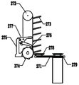
As shown in fig. 11, the steel belt feeding device 27 includes a fixed frame 271, a sprocket set 272, a steel belt bracket 273, a ratchet wheel 274, a main pawl 275, an auxiliary pawl 276, a hand lever 277, a steel belt tray 278, and a push cylinder 279.
The fixed mount is horizontally fixed on the anchoring rack 22; the chain wheel set 272 is vertically arranged on the fixing frame 271, the chain wheel set 272 comprises an upper chain wheel and a lower chain wheel, and the chain wheels are connected through a chain; a steel belt support 273 is arranged on the chain and used for placing a steel belt; the ratchet wheel 274 is connected with the chain wheel set 272 in a matching way through a flat key; the hand lever 277 is hinged with the anchoring rack 22 through a pin shaft; the main pawl 275 and the auxiliary pawl 276 are respectively hinged with a hand-operated rod 277, the hand-operated rod 277 is toggled to drive a ratchet wheel 274 to rotate, the ratchet wheel 274 rotates to drive a chain wheel set 272 to rotate, the chain wheel set 272 rotates to drive a steel belt supporting frame 273 to descend, and the steel belt supporting frame 272 falls into a steel belt tray 278 arranged on the fixed frame 271; the bottom of the steel belt tray 278 is provided with a roller which is pushed by a pushing oil cylinder 279 to move to the upper part of the top anchor rod drilling machine 24, and the top anchor rod drilling machine 24 drives the steel belt into a roadway to finish the steel belt arrangement operation. The steel belt is matched with the anchor rod and the anchor cable, so that the roadway is reinforced more firmly.
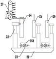
As shown in fig. 12 and 13, the timbering mechanism 30 includes a primary timbering frame 31, a secondary timbering frame 32, a restraint rail 33, a timbering mechanism traveling motor 34, a circulating timbering roof 35, and a side wall timbering 36.
The primary support frame 31 includes two primary support struts 311 and a primary support cross beam 312 connecting the two primary support struts 311; the main supporting struts 311 are vertically arranged, the walking tracks are arranged at the bottoms of the main supporting struts 311, and the main supporting frame 31 can freely move under the driving of the supporting mechanism walking motors 34.
The secondary support frame 32 is arranged in parallel with the primary support frame 31; the secondary support frame 32 includes two secondary support struts 321 and a secondary support cross beam 322 connecting the two secondary support struts 321; the bottom of the secondary support strut 321 is provided with a slipper, and the secondary support frame 32 slides on the ground through the slipper.
The primary support frame 31 is matched with the secondary support frame 32 through the constraint rail 33, the constraint rail 33 constrains the primary support frame 31 and the secondary support frame 32 to only generate displacement in the X-axis direction, and no relative displacement exists in the Y-axis direction and the Z-axis direction.
The auxiliary supporting frame 32 is sleeved outside the main supporting frame 31, and the main supporting frame 31 is sleeved on the front section 11 of the tunneling mechanism to provide support for the tunneling mechanism 10.
The main supporting rod 311 and the auxiliary supporting rod 321 are both provided with telescopic cylinders to drive the main supporting rod 311 and the auxiliary supporting rod 321 to extend and retract in the Z-axis direction; the circulating support top plate 35 is fixed at the top ends of the main support cross beam 312 and the secondary support cross beam 322 and is used for supporting the top surface of the roadway; the side wall supports 36 are vertically fixed on the side wall of the secondary support strut 321 facing the roadway, and two groups of side wall supports 36 are arranged in a staggered manner and used for supporting the two side wall surfaces of the roadway.
The supporting mechanism 30 and the tunneling mechanism 10 are in a mutually matched relationship, the supporting mechanism 30 is provided with an independent power and traveling mechanism, and when the supporting mechanism operates, the supporting mechanism covers the front section of the tunneling mechanism 10 to provide temporary support for the tunneling mechanism 10, and permanent support is achieved by the anchoring mechanism 20 arranged on the rear section 15 of the tunneling mechanism.
The supporting mechanism 30 and the top wall of the roadway are always kept in stable contact and supporting relation, and the front section 11 of the tunneling mechanism and the rear section 15 of the tunneling mechanism simultaneously move forwards to preset positions; the main supporting frame 31 of the supporting mechanism contracts and is separated from the circulating supporting top plate 35, and after the main supporting frame 31 extends again and supports the circulating supporting top plate 35 after the main supporting frame travels a certain distance towards the tunneling direction; the secondary timbering frames 32 are then retracted away from the circulating timbering roof 35 and slid in the forward driving direction under the traction of the restraint rails 33, and after traveling the same distance as the primary timbering frames 31, the secondary timbering frames 32 are extended and re-support the circulating timbering roof 35. In the process, the side wall supports 36 on the secondary support strut 321 are arranged in a staggered manner, so that the side wall supports 36 always have a support effect on the side wall of the roadway.
A working method of a four-stage sliding cutting type excavating, supporting, anchoring and transporting four-wheel drive combined device specifically comprises the following steps:
s1, covering the front section 11 of the tunneling mechanism by a supporting mechanism, and fixing an anchoring mechanism at the rear section 15 of the tunneling mechanism; a telescopic cutting head 13 of the tunneling mechanism and the three-degree-of-freedom cutting platform 12 are cooperatively controlled to cut the section of the front end of the roadway into a preset depth according to a preset contour; the three-degree-of-freedom cutting platform 12 can enable the telescopic cutting head 13 to have moving degrees of freedom in the directions of an X axis, a Y axis and a Z axis;
s2, loading the coal cinder materials accumulated on the ground onto the scraper conveyor 16 by the full-section shovel board 113, and transporting the coal cinder materials to a designated position backwards;
s3, in the tunneling process of the tunneling device, the top anchor rod drilling machine 24, the side anchor rod drilling machine 25 and the anchor cable drilling machine 26 of the anchoring mechanism 20 work simultaneously, anchor rods and anchor cables are nailed into the coal wall of the roadway, and the roadway top wall and the roadway side wall around the anchoring mechanism are supported permanently;
s4, synchronously starting the steel belt feeding device 27, and providing steel belts for the top anchor rod drilling machine 24, the side anchor rod drilling machine 25 and the anchor cable drilling machine when the top anchor rod drilling machine 24, the side anchor rod drilling machine 25 and the anchor cable drilling machine work;
s5, the supporting mechanism 30 and the top wall of the roadway are always in stable contact and supporting relation, and after S2-S4 are completed, the front section 11 of the tunneling mechanism and the rear section 15 of the tunneling mechanism simultaneously move forwards to preset positions; the main supporting frame 31 of the supporting mechanism contracts and is separated from the circulating supporting top plate 35, and after the main supporting frame 31 travels a preset distance in the tunneling direction, the main supporting frame 31 extends again and supports the circulating supporting top plate 35; then the secondary supporting frame 32 contracts to be separated from the circulating supporting top plate 35, slides in the forward tunneling direction under the traction of the constraint track 33, and extends out of the secondary supporting frame 32 and supports the circulating supporting top plate 35 again after the secondary supporting frame travels the same distance with the main supporting frame 31;
s6, the anchoring mechanism 20 is clamped with the rear frame 152 through the dragging rod 154; after the rear section 15 of the tunneling mechanism moves towards the tunneling direction, the anchoring mechanism 20 is dragged to move and keeps still relative to the tunneling mechanism 10;
s7, when the roadway bottom is uneven, the multi-degree-of-freedom connecting mechanism 14 enables the relative position of the front section 11 of the tunneling mechanism and the rear section 15 of the tunneling mechanism to change along with the terrain, and ensures good ground contact effect of the whole machine.
The tunneling mechanism can realize four-stage sliding, and can realize full-face cutting under the condition that the tunneling host is not moved; the full-section shovel plate can realize the functions of overturning, stretching, small star wheel auxiliary operation and the like, and can realize full-section shoveling operation; the front section and the rear section of the tunneling mechanism are driven to travel in four directions, so that the actions of rotation, torsion, pitching and the like can be realized, and the tunneling mechanism has high horsepower and strong climbing capability. The supporting mechanism can realize the operation of leaving the machine with the tunneling main machine, and has the effect of supporting the top plate and the side wall of the roadway without repeated rolling. The anchoring mechanism is treated in a modularized way, so that rapid assembly and separation can be realized; the anchoring mechanism can realize multi-process operation of top anchoring, side anchoring and anchor rope, has the function of mechanically feeding steel strips, and can effectively improve the anchoring efficiency.
Although the preferred embodiments of the present invention have been described in detail, the present invention is not limited to the details of the embodiments, and various equivalent changes may be made within the technical spirit of the present invention, and the technical scope of the present invention is also covered by the present invention.
Claims (7)
1. The utility model provides a level four cutting type that slides digs a fortune four-wheel drive aggregate unit which characterized in that: comprises a tunneling mechanism (10), an anchoring mechanism (20) and a supporting mechanism (30);
defining the direction of rapid tunneling in a roadway as an X-axis direction, the main supporting direction of a supporting mechanism as a Z-axis direction, and the side wall supporting direction of the supporting mechanism as a Y-axis direction;
the tunneling mechanism (10) comprises a tunneling mechanism front section (11), a three-degree-of-freedom cutting platform (12), a telescopic cutting head (13), a multi-degree-of-freedom connecting mechanism (14), a tunneling mechanism rear section (15) and a scraper conveyor (16);
the front section (11) of the tunneling mechanism comprises a front walking mechanism (111), a main frame (112) and a full-face shovel plate (113);
the front travelling mechanism (111) is a crawler-type travelling device; the top of the front walking mechanism (111) is fixed with a main frame (112); the full-section shovel plate (113) is hinged with the main frame (112), and the rotating direction of the full-section shovel plate (113) is that the plane where the X axis and the Y axis are located rotates to the plane where the Y axis and the Z axis are located;
a three-degree-of-freedom cutting platform (12) is fixed at the top of the main frame (112); the three-degree-of-freedom cutting platform (12) comprises an X axial pushing platform (121), an X axial guiding device (122), a Y axial pushing platform (123), a Y axial guiding device (124), a rotary platform (125) and a rotary device (126);
the X-axial pushing platform (121) and the X-axial guiding device (122) form a sliding pair moving in the X-axial direction and relatively slide in the X-axial direction; the Y-axis pushing platform (123) and the Y-axis guiding device (124) form a sliding pair moving in the Y-axis direction and relatively slide in the Y-axis direction; the rotary platform (125) and the rotary device (126) form a hinge pair which can rotate 360 degrees on a plane formed by an X axis and a Y axis;
a telescopic cutting head (13) is fixed at the top of the three-degree-of-freedom cutting platform (12); the telescopic cutting head (13) is used for cutting a coal wall during rapid tunneling; the multi-degree-of-freedom connecting mechanism (14) comprises a torsion joint (141), a rotary joint (142) and a pitching joint (143); the torsional joint (141) provides a rotational degree of freedom in the X-axis direction; a rotary joint (142) providing rotational freedom in the Y-axis direction; the pitch joint (143) provides a rotational degree of freedom in the Z-axis direction;
the rear section (15) of the tunneling mechanism comprises a rear travelling mechanism (151), a rear frame (152) and a power device (153);
the rear travelling mechanism (151) is a crawler-type travelling device; a rear frame (152) is fixed at the top of the rear travelling mechanism (151); a power device (153) is fixed on the rear frame (152), and the power device (153) provides walking power for the rear walking mechanism (151); a trailing rod (154) is also fixed on the rear frame (152);
the scraper conveyor (16) is fixed at the top of the rear frame, and the scraper conveyor (16) is connected with a full-section shovel plate (113);
the anchoring mechanism (20) comprises an anchoring base (21), an anchoring rack (22), a groove seat (23), a top anchor drilling machine (24) and a side anchor drilling machine (25);
the bottom of the anchoring base (21) is provided with a sliding shoe, and the anchoring base (21) slides on the ground through the sliding shoe; a groove seat (23) is fixed at the top of the anchoring base (21), the groove seat (23) is clamped with a dragging rod (154) on the rear rack, and the anchoring base (21) is connected with the rear rack (152);
an anchoring rack (22) is vertically fixed at the top of the anchoring base (21); a top anchor rod drilling machine (24) and a side anchor rod drilling machine (25) are fixed on the anchoring frame (22); the top anchor rod drilling machine (24) nails an anchor rod into the top of the roadway along the Z-axis direction; the side anchor rod drilling machine (25) nails the anchor rods into two side walls of the roadway along the Y-axis direction;
the supporting mechanism (30) comprises a main supporting frame (31), an auxiliary supporting frame (32), a restraint track (33), a supporting mechanism walking motor (34), a circulating supporting top plate (35) and a side wall support (36);
the primary support frame (31) comprises two primary support struts (311) and a primary support cross beam (312) connected with the two primary support struts (311); the main supporting rods (311) are vertically arranged, the bottom of each main supporting rod (311) is provided with a walking crawler, and the main supporting frame (31) can freely move under the driving of a walking motor (34) of the supporting mechanism;
the auxiliary supporting frame (32) and the main supporting frame (31) are arranged in parallel; the secondary support frame (32) comprises two secondary support struts (321) and a secondary support cross beam (322) connected with the two secondary support struts (321); the bottom of the secondary supporting strut (321) is provided with a sliding shoe, and the secondary supporting frame (32) slides on the ground through the sliding shoe;
the main supporting frame (31) is matched with the auxiliary supporting frame (32) through a constraint track (33), the constraint track (33) constrains the main supporting frame (31) and the auxiliary supporting frame (32) to only generate displacement in the X-axis direction, and no relative displacement exists in the Y-axis direction and the Z-axis direction;
the auxiliary supporting frame (32) is sleeved outside the main supporting frame (31), and the main supporting frame (31) is sleeved on the front section (11) of the tunneling mechanism to support the tunneling mechanism (10);
the main supporting rod (311) and the auxiliary supporting rod (321) are both provided with telescopic cylinders to drive the main supporting rod (311) and the auxiliary supporting rod (321) to stretch in the Z-axis direction;
the circulating supporting top plate (35) is fixed at the top ends of the main supporting cross beam (312) and the auxiliary supporting cross beam (322) and is used for supporting the top surface of the roadway;
and the side wall supports (36) are vertically fixed on the side wall of the auxiliary support rod (321) facing the roadway and are used for supporting the two side wall surfaces of the roadway.
2. The four-stage slipping cutting type tunneling, supporting, anchoring and transporting four-wheel drive combined device according to claim 1, wherein: the full-section shovel plate (113) comprises a main shovel plate (1131), a main star wheel (1132) and a side shovel plate (1133);
the main shovel plate (1131) is hinged with the main frame (112), and the main shovel plate (1131) realizes pitching rotation by taking the Y-axis direction as a rotating shaft; a main star wheel (1132) is arranged on the main shovel plate (1131), the main star wheel (1132) is used for rotationally scraping coal and conveying the coal cut by the telescopic cutting head (13) into a scraper conveyor (16);
the side shovel plate (1133) is hinged with the main shovel plate (1131), and the side shovel plate (1133) uses an X axis as a rotating shaft to realize pitching rotation.
3. The four-stage slipping cutting type tunneling, supporting, anchoring and transporting four-wheel drive combined device as claimed in claim 2, wherein: the full-section shovel plate (113) further comprises a telescopic shovel plate (1134), an auxiliary shovel plate (1135) and an auxiliary star wheel (1136);
the telescopic shovel plate (1134) is connected with the side shovel plate (1133) through a built-in oil cylinder, and the telescopic shovel plate (1134) can be expanded in a telescopic mode in the Y-axis direction; an auxiliary star wheel (1136) is fixed on the telescopic shovel plate (1134); the auxiliary star wheel (1136) continuously rotates to enable the coal on the full-section shovel plate (113) to be in a floating state all the time;
the auxiliary shovel plate (1135) is in threaded connection with the telescopic shovel plate (1134), and can be flexibly detached.
4. The four-stage slipping cutting type tunneling, supporting, anchoring and transporting four-wheel drive combined device according to claim 1, wherein: the anchoring mechanism further comprises a cable drill (26); the anchor cable drilling machine (26) is fixed on the anchoring rack (22) along the X-axis direction and the Y-axis direction respectively; the anchor cable drilling machine (26) nails the anchor cable into the top of the roadway and two side walls of the roadway.
5. The four-stage slipping cutting type tunneling, supporting, anchoring and transporting four-wheel drive combined device as claimed in claim 1, wherein: the anchoring mechanism further comprises a steel belt feeding device (27); the steel belt feeding device (27) is fixed on the anchoring rack (22);
the steel belt loading device (27) comprises a fixed frame (271), a chain wheel set (272), a steel belt support frame (273), a ratchet wheel (274), a main pawl (275), an auxiliary pawl (276), a hand lever (277), a steel belt tray (278) and a pushing cylinder (279);
the fixed frame is horizontally fixed on the anchoring rack (22); the chain wheel set (272) is vertically arranged on the fixed frame (271), the chain wheel set (272) comprises an upper chain wheel and a lower chain wheel, and the chain wheels are connected through a chain; a steel belt support frame (273) is arranged on the chain and used for placing a steel belt; the ratchet wheel (274) is matched and connected with the chain wheel set (272) through a flat key; the hand-operated rod (277) is hinged with the anchoring rack (22) through a pin shaft; the main pawl (275) and the auxiliary pawl (276) are respectively hinged with a hand-operated rod (277), the hand-operated rod (277) is toggled to drive a ratchet wheel (274) to rotate, the ratchet wheel (274) rotates to drive a chain wheel set (272) to rotate, the chain wheel set (272) rotates to drive a steel strip support frame (273) to descend, and the steel strip support frame (272) falls into a steel strip tray (278) arranged on the fixed frame (271); the bottom of the steel belt tray (278) is provided with a roller, the roller is pushed by a pushing oil cylinder (279) to move to the upper part of the top anchor rod drilling machine (24), and the top anchor rod drilling machine (24) drives a steel belt into a roadway to finish steel belt arrangement operation.
6. The four-stage slipping cutting type tunneling, supporting, anchoring and transporting four-wheel drive combined device according to claim 1, wherein: the side faces, facing the roadway, of the auxiliary supporting struts (321) are respectively provided with a side wall support (36), each auxiliary supporting strut (321) is provided with two groups of side wall supports (36), and the two groups of side wall supports (36) are arranged in a staggered mode.
7. The working method of the four-stage slipping cutting type tunneling, support, anchoring and transporting four-wheel drive combined device based on claim 6 is characterized in that: the method specifically comprises the following steps:
s1, the front section (11) of the tunneling mechanism is covered by the support mechanism, and the anchoring mechanism is fixed on the rear section (15) of the tunneling mechanism; a telescopic cutting head (13) of the tunneling mechanism and a three-degree-of-freedom cutting platform (12) are cooperatively controlled to cut the section of the front end of the roadway into a preset depth according to a preset profile; the three-degree-of-freedom cutting platform (12) can enable the telescopic cutting head (13) to have moving degrees of freedom in the directions of an X axis, a Y axis and a Z axis;
s2, loading the coal slag materials accumulated on the ground onto a scraper conveyor (16) by a full-section shovel plate (113), and transporting the coal slag materials to a designated position backwards;
s3, in the tunneling process of the tunneling device, a top anchor rod drilling machine (24), a side anchor rod drilling machine (25) and an anchor cable drilling machine (26) of the anchoring mechanism (20) work simultaneously, an anchor rod and an anchor cable are nailed into the coal wall of the roadway, and the top wall and the side wall of the roadway around the anchoring mechanism are permanently supported;
s4, synchronously starting a steel belt feeding device (27), and providing steel belts for the top anchor rod drilling machine (24), the side anchor rod drilling machine (25) and the anchor cable drilling machine when the top anchor rod drilling machine (24), the side anchor rod drilling machine (25) and the anchor cable drilling machine work;
s5, the supporting mechanism (30) and the top wall of the roadway are always in stable contact and supporting relation, and after S2-S4 is completed, the front section (11) of the tunneling mechanism and the rear section (15) of the tunneling mechanism simultaneously move forwards to a preset position; the main supporting frame (31) of the supporting mechanism contracts and is separated from the circulating supporting top plate (35), and after the main supporting frame (31) drives for a preset distance in the tunneling direction, the main supporting frame stretches again and supports the circulating supporting top plate (35); then the secondary supporting frame (32) is contracted to be separated from the circulating supporting roof (35), slides in the forward tunneling direction under the traction of the constraint track (33), and extends out and supports the circulating supporting roof (35) again after the secondary supporting frame (32) travels the same distance with the main supporting frame (31);
s6, the anchoring mechanism (20) is clamped with the rear frame (152) through the dragging rod (154); after the rear section (15) of the tunneling mechanism moves towards the tunneling direction, the anchoring mechanism (20) is dragged to move and keeps still relative to the tunneling mechanism (10);
s7, when the roadway bottom is uneven, the multi-degree-of-freedom connecting mechanism (14) enables the relative position of the front section (11) of the tunneling mechanism and the rear section (15) of the tunneling mechanism to change along with the terrain, and the good ground contact effect of the whole machine is ensured.
Priority Applications (1)
| Application Number | Priority Date | Filing Date | Title |
|---|---|---|---|
| CN202210260074.3A CN114718588A (en) | 2022-03-16 | 2022-03-16 | Four-stage sliding cutting type four-wheel drive combined device for digging, supporting, anchoring and transporting and working method |
Applications Claiming Priority (1)
| Application Number | Priority Date | Filing Date | Title |
|---|---|---|---|
| CN202210260074.3A CN114718588A (en) | 2022-03-16 | 2022-03-16 | Four-stage sliding cutting type four-wheel drive combined device for digging, supporting, anchoring and transporting and working method |
Publications (1)
| Publication Number | Publication Date |
|---|---|
| CN114718588A true CN114718588A (en) | 2022-07-08 |
Family
ID=82238395
Family Applications (1)
| Application Number | Title | Priority Date | Filing Date |
|---|---|---|---|
| CN202210260074.3A Pending CN114718588A (en) | 2022-03-16 | 2022-03-16 | Four-stage sliding cutting type four-wheel drive combined device for digging, supporting, anchoring and transporting and working method |
Country Status (1)
| Country | Link |
|---|---|
| CN (1) | CN114718588A (en) |
Cited By (2)
| Publication number | Priority date | Publication date | Assignee | Title |
|---|---|---|---|---|
| CN114941534A (en) * | 2022-07-22 | 2022-08-26 | 山西天地煤机装备有限公司 | Heading machine and heading method |
| CN115075839A (en) * | 2022-07-22 | 2022-09-20 | 山西天地煤机装备有限公司 | Rock boring machine and rock roadway boring method |
-
2022
- 2022-03-16 CN CN202210260074.3A patent/CN114718588A/en active Pending
Cited By (3)
| Publication number | Priority date | Publication date | Assignee | Title |
|---|---|---|---|---|
| CN114941534A (en) * | 2022-07-22 | 2022-08-26 | 山西天地煤机装备有限公司 | Heading machine and heading method |
| CN115075839A (en) * | 2022-07-22 | 2022-09-20 | 山西天地煤机装备有限公司 | Rock boring machine and rock roadway boring method |
| CN115075839B (en) * | 2022-07-22 | 2022-11-04 | 山西天地煤机装备有限公司 | Rock tunneling machine and rock roadway tunneling method |
Similar Documents
| Publication | Publication Date | Title |
|---|---|---|
| US8317430B2 (en) | Crawler-type and height adjustment drilling machine for setting roof and side wall anchor bolts and anchor cables | |
| CN111140245B (en) | Intelligent tunnel digging and supporting machine and method for rapidly forming tunnel | |
| CN114718588A (en) | Four-stage sliding cutting type four-wheel drive combined device for digging, supporting, anchoring and transporting and working method | |
| US4056284A (en) | Machines for use in mining or tunnelling work | |
| EP0157286B1 (en) | Conveyor belt system for a continuous mining machine | |
| CN107060802A (en) | Rock-gangway bomb-dug bores shipment complete set of equipments | |
| CN101169036B (en) | Pedrail type lifting top slope anchor shaft anchor cable construction drilling machine and single-alley fast tunneling technique | |
| CN111485900A (en) | Rock tunnel boring machine | |
| CN103742176A (en) | Excavating and anchor-supporting all-in-one unit | |
| CN201794610U (en) | Drilling, loading, anchoring, supporting and transporting integrated machine in high outburst mine coal drift | |
| CN213478364U (en) | Stock reprints unit | |
| CN101975077B (en) | High-outburst coal mine coal roadway drilling-loading-bolting integrated machine | |
| CN106979015A (en) | A kind of climbing control method of the high inclination-angle development machine with auxiliary climbing apparatus | |
| CN101403302A (en) | Pedrail type liftable anchor bar anchor cable construction drill rig and double-lane fast digging technique | |
| CN101781972B (en) | Crawler-type lifting top and slope bolt and anchor construction drill | |
| CN203742636U (en) | Tunneling, supporting and anchoring integrated unit | |
| US3834761A (en) | Deep-mine augering machine | |
| AU2004216593B2 (en) | Combination panline and utility drilling or bolting unit | |
| CN102425415A (en) | Gangue racking machine for half-coal rock roadway blasting driving | |
| CN217001866U (en) | Flexible arm tunneling machine | |
| CN206888989U (en) | Rock-gangway bomb-dug bores shipment complete set of equipments | |
| RU2103507C1 (en) | Method and cutter-loader machine for development of seam deposits of minerals | |
| CN114320417A (en) | Anchoring forward-moving type rapid tunneling and supporting device and working method thereof | |
| CN106869956A (en) | A kind of high inclination-angle development machine with auxiliary climbing apparatus | |
| US9810024B2 (en) | Drill system |
Legal Events
| Date | Code | Title | Description |
|---|---|---|---|
| PB01 | Publication | ||
| PB01 | Publication | ||
| SE01 | Entry into force of request for substantive examination | ||
| SE01 | Entry into force of request for substantive examination |