RU2043983C1 - Installation for ventilation and regulation of moist and fermentable organic product - Google Patents
Installation for ventilation and regulation of moist and fermentable organic product Download PDFInfo
- Publication number
- RU2043983C1 RU2043983C1 SU4743114/15A SU4743114A RU2043983C1 RU 2043983 C1 RU2043983 C1 RU 2043983C1 SU 4743114/15 A SU4743114/15 A SU 4743114/15A SU 4743114 A SU4743114 A SU 4743114A RU 2043983 C1 RU2043983 C1 RU 2043983C1
- Authority
- RU
- Russia
- Prior art keywords
- installation according
- reactor
- perforated
- paragraphs
- product
- Prior art date
Links
Images


Classifications
-
- F—MECHANICAL ENGINEERING; LIGHTING; HEATING; WEAPONS; BLASTING
- F26—DRYING
- F26B—DRYING SOLID MATERIALS OR OBJECTS BY REMOVING LIQUID THEREFROM
- F26B9/00—Machines or apparatus for drying solid materials or objects at rest or with only local agitation; Domestic airing cupboards
- F26B9/10—Machines or apparatus for drying solid materials or objects at rest or with only local agitation; Domestic airing cupboards in the open air; in pans or tables in rooms; Drying stacks of loose material on floors which may be covered, e.g. by a roof
-
- C—CHEMISTRY; METALLURGY
- C05—FERTILISERS; MANUFACTURE THEREOF
- C05F—ORGANIC FERTILISERS NOT COVERED BY SUBCLASSES C05B, C05C, e.g. FERTILISERS FROM WASTE OR REFUSE
- C05F17/00—Preparation of fertilisers characterised by biological or biochemical treatment steps, e.g. composting or fermentation
- C05F17/70—Controlling the treatment in response to process parameters
-
- C—CHEMISTRY; METALLURGY
- C05—FERTILISERS; MANUFACTURE THEREOF
- C05F—ORGANIC FERTILISERS NOT COVERED BY SUBCLASSES C05B, C05C, e.g. FERTILISERS FROM WASTE OR REFUSE
- C05F17/00—Preparation of fertilisers characterised by biological or biochemical treatment steps, e.g. composting or fermentation
- C05F17/90—Apparatus therefor
- C05F17/914—Portable or transportable devices, e.g. transport containers or trucks
-
- C—CHEMISTRY; METALLURGY
- C05—FERTILISERS; MANUFACTURE THEREOF
- C05F—ORGANIC FERTILISERS NOT COVERED BY SUBCLASSES C05B, C05C, e.g. FERTILISERS FROM WASTE OR REFUSE
- C05F17/00—Preparation of fertilisers characterised by biological or biochemical treatment steps, e.g. composting or fermentation
- C05F17/90—Apparatus therefor
- C05F17/964—Constructional parts, e.g. floors, covers or doors
- C05F17/971—Constructional parts, e.g. floors, covers or doors for feeding or discharging materials to be treated; for feeding or discharging other material
- C05F17/979—Constructional parts, e.g. floors, covers or doors for feeding or discharging materials to be treated; for feeding or discharging other material the other material being gaseous
-
- F—MECHANICAL ENGINEERING; LIGHTING; HEATING; WEAPONS; BLASTING
- F26—DRYING
- F26B—DRYING SOLID MATERIALS OR OBJECTS BY REMOVING LIQUID THEREFROM
- F26B1/00—Preliminary treatment of solid materials or objects to facilitate drying, e.g. mixing or backmixing the materials to be dried with predominantly dry solids
-
- F—MECHANICAL ENGINEERING; LIGHTING; HEATING; WEAPONS; BLASTING
- F26—DRYING
- F26B—DRYING SOLID MATERIALS OR OBJECTS BY REMOVING LIQUID THEREFROM
- F26B21/00—Arrangements or duct systems, e.g. in combination with pallet boxes, for supplying and controlling air or gases for drying solid materials or objects
- F26B21/06—Controlling, e.g. regulating, parameters of gas supply
- F26B21/12—Velocity of flow; Quantity of flow, e.g. by varying fan speed, by modifying cross flow area
-
- F—MECHANICAL ENGINEERING; LIGHTING; HEATING; WEAPONS; BLASTING
- F26—DRYING
- F26B—DRYING SOLID MATERIALS OR OBJECTS BY REMOVING LIQUID THEREFROM
- F26B3/00—Drying solid materials or objects by processes involving the application of heat
- F26B3/32—Drying solid materials or objects by processes involving the application of heat by development of heat within the materials or objects to be dried, e.g. by fermentation or other microbiological action
-
- Y—GENERAL TAGGING OF NEW TECHNOLOGICAL DEVELOPMENTS; GENERAL TAGGING OF CROSS-SECTIONAL TECHNOLOGIES SPANNING OVER SEVERAL SECTIONS OF THE IPC; TECHNICAL SUBJECTS COVERED BY FORMER USPC CROSS-REFERENCE ART COLLECTIONS [XRACs] AND DIGESTS
- Y02—TECHNOLOGIES OR APPLICATIONS FOR MITIGATION OR ADAPTATION AGAINST CLIMATE CHANGE
- Y02P—CLIMATE CHANGE MITIGATION TECHNOLOGIES IN THE PRODUCTION OR PROCESSING OF GOODS
- Y02P20/00—Technologies relating to chemical industry
- Y02P20/141—Feedstock
- Y02P20/145—Feedstock the feedstock being materials of biological origin
-
- Y—GENERAL TAGGING OF NEW TECHNOLOGICAL DEVELOPMENTS; GENERAL TAGGING OF CROSS-SECTIONAL TECHNOLOGIES SPANNING OVER SEVERAL SECTIONS OF THE IPC; TECHNICAL SUBJECTS COVERED BY FORMER USPC CROSS-REFERENCE ART COLLECTIONS [XRACs] AND DIGESTS
- Y02—TECHNOLOGIES OR APPLICATIONS FOR MITIGATION OR ADAPTATION AGAINST CLIMATE CHANGE
- Y02W—CLIMATE CHANGE MITIGATION TECHNOLOGIES RELATED TO WASTEWATER TREATMENT OR WASTE MANAGEMENT
- Y02W30/00—Technologies for solid waste management
- Y02W30/40—Bio-organic fraction processing; Production of fertilisers from the organic fraction of waste or refuse
Abstract
Description
Изобретение относится к области сельского хозяйства, в частности к установкам для переработки органических отходов путем аэробного брожения. The invention relates to the field of agriculture, in particular to installations for the processing of organic waste by aerobic fermentation.
Для ускорения процесса компостирования предлагалось множество решений с использованием принудительной аэрации, например с вдуванием или всасыванием воздуха или газа [1] Однако они не могут быть использованы в промышленных масштабах. To speed up the composting process, many solutions have been proposed using forced aeration, for example, by blowing or sucking in air or gas [1] However, they cannot be used on an industrial scale.
В известном способе предлагается регулировать респираторную активность продуктов в процессе обработки, регулируя количество вдуваемого в них воздуха в зависимости от величины, такой как содержание углекислого газа в выходящих газах или температура, на практике температура самих этих продуктов, принимая ее в качестве отражения этой активности [2]
Целью изобретения является устройство для обработки биологическим путем сырого и способного к брожению органического продукта, обеспечивающее успешную промышленную эксплуатацию.In the known method, it is proposed to regulate the respiratory activity of the products during processing, by adjusting the amount of air blown into them depending on the value, such as the carbon dioxide content in the exhaust gases or temperature, in practice, the temperature of these products themselves, taking it as a reflection of this activity [2 ]
The aim of the invention is a device for the biological processing of raw and fermentable organic product, ensuring successful industrial operation.
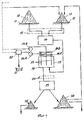
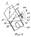
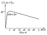
На фиг. 1 показана блок-диаграмма различных этапов обработки; на фиг.2 установка вентиляции и регулирования для обработки влажного и способного к брожению органического продукта, общий вид в аксонометрии; на фиг.3 разрез А-А на фиг. 2; на фиг.4 разрез Б-Б на фиг.2; на фиг.5 вид по стрелке В на фиг. 4; на фиг.6 узел I на фиг.5; на фиг.7 узел II на фиг.6; на фиг.8 график изменения продукта в процессе обработки в установке согласно изобретению; на фиг. 9 вариант выполнения фиг.3, поперечный разрез; на фиг.10 вариант выполнения фиг.2. In FIG. 1 is a flowchart of various processing steps; figure 2 installation of ventilation and regulation for the processing of wet and fermentable organic product, General view in a perspective view; in Fig.3 a section aa in Fig. 2; in Fig.4 a section bB in Fig.2; in Fig.5 a view along arrow B in Fig. 4; in Fig.6 node I in Fig.5; in Fig.7 node II in Fig.6; on Fig graph of product changes during processing in the installation according to the invention; in FIG. 9 embodiment of figure 3, a cross section; figure 10 embodiment of figure 2.
Как показано на фиг.1 обрабатываемый продукт 10 хранится на любой складской площадке 11. Если речь идет об обезвоживаемом сыром продукте, то такое складирование предпочтительно осуществляется под навесом (не показан). Таким путем обеспечивается предварительный нагрев продукта 10. Для этого достаточно в качестве навеса использовать прозрачный навес. В этом случае воздух, соприкасающийся с таким покрытием, сам предварительно нагревается, за счет чего и достигается дополнительное преимущество. As shown in figure 1, the processed
В примере выполнения на другой складской площадке 12 находится другой продукт 13, который примешивается к обрабатываемому продукту 10 перед его обработкой, причем продукт 13 выбирается таким, чтобы он был способен придать смеси натуральные структурные свойства и облегчить тем самым циркуляцию воздуха. В зависимости от обрабатываемого продукта 10 может идти речь о продукте, который служит углеродистой добавкой, а также, например, кожуре, лавандовой соломе, виноградных отходах, кукурузных кочерыжках, отходах обрезки деревьев, древесных щепках, прутьях или других растительных отходах. Но речь может идти и о нейтральном продукте и (или) минеральном продукте, таком как галька или гравий. In an exemplary embodiment, another
На фиг.1 сплошной линией представлена обработка продукта, если он обладает удовлетворительной структурой. Прерывистой линией 15 на фиг.1 указано предварительное дозирование разных соответствующих ингредиентов. In figure 1, the solid line represents the processing of the product, if it has a satisfactory structure. The
На складских площадках 11, 12 отбор производится с помощью ковшовых механизмов, дозирование производится из расчета числа ковшей для отбора, например, по одному ковшу обрабатываемого продукта 10 на один-два ковша продукта 13. Если необходимо смешивание обрабатываемого продукта 10 с продуктом 13 и эвентуальными добавками сопровождается измельчением смеси. Полученная смесь загружается в реактор 16. At
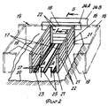
На фиг. 2-4 представлен реактор, который работает на открытом воздухе и который, открытый сверху в своей верхней части, просто образован стенками 17, 18, установленными прямо на земле 20 по прямоугольному контуру. В этом примере реактор 16 не имеет неподвижной стенки с одной из своих сторон, для того чтобы загрузочный или разгрузочный механизм мог проникать туда непосредственно. Эти стенки могут быть выполнены из бетона или из облицовочного камня, что очень просто и экономично. Они выполняются предпочтительно с помощью металлических опор 21 или деревянных рам 22, вставляющихся одна в другую, причем эти деревянные рамы 22 сами обладают соответствующими теплоизоляционными свойствами и могут легко заменяться при необходимости. Размеры реактора 16, ограниченного таким образом, не имеют никакого значения. Однако стенки 17 и 18 располагаются, по меньшей мере, на половину высоты этого продукта. Стенки 17 и 18 можно дополнить (прерывистой линией представлено на схеме фиг. 2), верхней стенкой 19, съемной, дополняющей эту боковую защиту, закрыв с его четвертой стороны этот реактор 16 после его загрузки. Основанием может быть естественное земляное основание 20, например, обработанное, например, смесью песок-цемент, а также покрытие из тонкого бетона или предохранительное покрытие. Основанию 20 придают небольшой наклон, чтобы облегчить стекание воды. In FIG. 2-4, a reactor is shown which operates in the open air and which, open at the top in its upper part, is simply formed by
В любом варианте реактор 16, согласно изобретению, имеет в своем основании перфорированную решетку 23, способную обеспечить циркуляцию воздуха через смесь, которая в нем содержится, с двумя установленными параллельно первичными баллонами 24А, 24В, каждый из которых может подключаться отдельно, первый для всасывания воздуха через лежащую под ней смесь, второй для вдувания воздуха в нее. In any embodiment, the
В примере выполнения, представленном на фиг.2-4, эта перфорированная решетка 23 имеет множество перфорированных каналов 25, которые расположены параллельно друг другу и обычно параллельно боковым стенкам 17 реактора 16, все соединены одним из своих концов с одним и тем же баллоном 26, называемым здесь для удобства вторичным баллоном, расположенным позади донной стенки 18 реактора 16, и которые другим своим концом все, каждый отдельно, находятся в тупике. In the exemplary embodiment shown in FIGS. 2-4, this perforated
В представленном примере выполнения предусмотрены три таких перфорированных канала 25 для образования между ними пространства, предназначенного для прохода загрузочного и/или разгрузочного механизма, расстояние между ними соответствует расстоянию между осями колес этого механизма. Речь идет, например, о трубах из синтетического материала, имеющих по их верхней образующей отверстия 27, например небольшие поперечные прорези. Предпочтительно иметь трубы из полиэтилена, так как этот материал прочен при вдавливании, дешев и довольно прост в обслуживании. Перфорированные каналы 25 в любом случае находятся прямо вровень с землей 20, выступая над ней только своей перфорированной частью. In the presented embodiment, three such
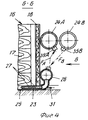
На фиг.3 перфорированные каналы 25 расположены каждый отдельно в желобе 28 из облицовочного камня, что позволяет легко заменять их при необходимости. В варианте выполнения на фиг.9 они могут быть врыты прямо в землю 20. In Fig.3, the
Перфорированные каналы 25 располагаются преимущественно строго горизонтально с небольшим обратным скатом в направлении вторичного баллона 26, с которым они соединены, и с ними соединены отводные средства, предназначенные для удаления оттуда конденсирующейся там воды, причем эти отводные средства состоят, например, из насоса 30, на отсосе которого подключен трубопровод 31, который соответствующими рукавами входит в перфорированные каналы 25, в их нижней части. По каналу 32 подача этого насоса 30 связана, например, с водостоком. Вторичный баллон 26 находится поперечно по отношению к перфорированным каналам 25, и он представляет собой отрезок трубопровода, закрытый на своих концах. Первичные баллоны 24А, 24В также как и вторичный баллон 26, лежат параллельно друг другу за донной стенкой 18 реактора 16, состоят, например, из отрезков труб. Каждый надлежащим образом соединены с воздуходувкой 34А, 34В, которая на фиг.2-4 не видна, но которая схематично представлена на фиг.1. Каждый из первичных баллонов 24А, 24В имеет Т-образную соединительную часть 35А, 35В, более или менее наклонную, через которую он может соединяться посредством мягкой манжеты 36 (фиг.5) с перфорированной решеткой 23 реактора 16. На практике подача воздуха, циркулирующего в составленном таким образом реакторе 16, контролируется регулирующим устройством, состоящим в комбинации, с одной стороны, из регулировочного клапана 37 и, с другой стороны, термометрического зонда 38, с которым связан указанный регулировочный клапан 37, и который проявляет чувствительность к температуре воздуха, выходящего из этого реактора 16. The
В примере выполнения регулировочный клапан 37 и термометрический зонд 38 расположены внутри камеры 39, находящейся между манжетой 36 и вторичным баллоном 26. Регулировочный клапан 37 выполнен в виде дроссельной заслонки. Термометрический зонд 38 имеет систему переменного объема, в которой предпочтительно содержится жидкость с большим коэффициентом теплового расширения и его стенка связана с приводом регулировочного клапана 37. В представленном примере выполнения система переменного объема термометрического зонда 38 образована двумя емкостями 40, 41, внутренние объемы которых соединены друг с другом проходом 42, и одна из которых, емкость 40, больше, чем другая, является неподвижной, тогда как другая емкость 41 меньше, чем предыдущая, имеет подвижную стенку 43. Как и емкость 40, емкость 41 может быть размещена внутри камеры 39. Только для большей ясности чертежа на фиг.6 эта камера представлена снаружи. В представленном примере выполнения подвижная стенка 43 выполнена в виде поршня, причем соответствующая емкость 41 выполнена, например, в виде шприца. Но в варианте выполнения эта подвижная стенка 43 может быть выполнена также из сильфона и даже представлять собой такой сильфон. Во всяком случае, эта подвижная стенка 43 сцеплена с приводом 44 регулировочного клапана 37 штоком 45. Несмотря на то, что привод 44 регулировочного клапана 37 состоит, например, из жесткой тяги, насаженной с возможностью вращения на оси этого регулировочного клапана 37, шток 45 предпочтительно является гибким. Кроме того, гибкий шток 45 преимущественно находится в зацеплении с приводом 44 с возможностью позиционного регулирования как продольно, так и поперечно. Например, как представлено на фиг.7, привод продольно имеет ряд отверстий 46, а гибкий шток 45, который имеет винтовую нарезку на своем конце, проходит сквозь одно из этих отверстий, блокируясь позиционно на этом приводе 44 двумя гайками 47, оказывающими свое воздействие каждая соответственно с той и другой его стороны. In an exemplary embodiment, the
Как схематично представлено на фиг.6, предусмотрен также на входе регулировочного клапана 37, в камере 39, клапан 48, называемый программирующим. Этот клапан 48 может быть с ручным управлением или механизированным. Помимо этого может быть предусмотрен один и тот же клапан программирующий и регулировочный, управляемый, например, серводвигателем. As shown schematically in FIG. 6, there is also provided at the inlet of the
Предпочтительно применять разные клапаны 24А, 24В и 26, а также систему трубопроводов, обслуживающих их, которые были бы термоизолирующими. На практике, как представлено прерывистой линией на фиг.2, установка включает несколько реакторов 16 в виде батареи, все имеющие сообща одни и те же первичные баллоны 24А, 24В. Например, этих реакторов 16 может быть четыре. Как бы там ни было, загрузка в такой реактор 16 обрабатываемой смеси производится предпочтительно на слой корки, чтобы избежать закрытия отверстий 27 перфорированных каналов 25, имеющихся в его основании. В смеси, размещенной таким образом в реакторе 16, в этом случае естественно происходит определенное брожение. Чтобы ускорить брожение, через эту смесь пропускают воздух в течение, по меньшей мере, части времени ее нахождения в реакторе 16. По существу такая циркуляция воздуха производится отсасыванием из первичного баллона 24А непрерывно. Для начала брожения и/или для возбуждения его периодически можно производить из первичного баллона 24В поддувку горячего и сухого воздуха сквозь смесь в процессе обработки ее в реакторе 16. Достаточно всякий раз последовательно подсоединять мягкую манжету 36 то к соединению первичного баллона 24А по стрелке FA на фиг.4, то к соединению 35В первичного баллона 24В по стрелке FB на этой фигуре. В том и другом случае давление воздуха может быть, например, порядка нескольких миллибар.It is preferable to use
Согласно изобретению, для регулирования подачи воздуха, циркулирующего в реакторе 16, определяют значение величины, связанной с состоянием обрабатываемого продукта 10, находящегося в этом реакторе 16, сравнивают измеренное таким образом значение этой величины с данным значением, запрограммированным заранее, и считающимся идеальным для подачи воздуха в данный момент, изменяют эту подачу воздуха, если измеренное значение соответствующей величины отклоняется от этого идеального значения. На практике величиной, выбранной для этой цели, обычно является температура выходящего воздуха. Но в этом случае может идти речь и о степени влажности этого выходящего воздуха или о его составе и, в частности, о содержании в нем энзимов и их природе, или также о любой другой величине, способной отражать состояние в данный момент продукта 10 в процессе обработки. Но оказывается, что температура выходящего воздуха, которую легко определить, является наиболее значимой для этого. Оказывается также, что через определенное время, например порядка недели, идеальное значение для температуры выходящего воздуха развивается почти линейно. According to the invention, to regulate the flow of air circulating in the
На фиг. 8 на оси абсцисс нанесено время (t), в днях, а на оси ординат температура (Т) воздуха, выходящего из реактора 16, в градусах, или подача воздуха Д, всасываемого через этот реактор. Соответствующая кривая, сначала поднимающаяся, следующая по прямой наклона относительно высокого, затем опускается по прямой наклона более слабого, чем предыдущий. Разумеется эта кривая меняется по амплитуде в зависимости от обрабатываемого продукта. Но опыт показывает, что ход ее одинаков для их смеси. В период первой фазы при повышении температуры нужно, следовательно, увеличить подачу всасываемого воздуха. Во время второй фазы, более длительной, при падении температуры следует, наоборот, параллельно уменьшить эту подачу воздуха. In FIG. 8, the time (t) is plotted on the abscissa axis, in days, and on the ordinate axis the temperature (T) of the air leaving the
Отмечено, что в течение первых пяти дней в реакторе, содержащем около 40-50 т обрабатываемого продукта 10, возможно пропускать около 500 м3/ч воздуха, температура которого на выходе составляет, например, 47-52оС, и степень влажности которого в этом случае равна 100, что соответствует в целом извлечению одной тонны воды ежедневно. Между пятым и десятым днями температура выходящего воздуха обычно не больше, чем 47-40оС, и подача воздуха может достигать 450 м3/ч. В течение последующих пяти дней температура выходящего воздуха падает с 42 до 37оС, и подача воздуха может достигать 400 м3/ч. В течение следующих пяти дней температура выходящего воздуха падает еще больше от 37 до 32оС, а соответствующая подача воздуха может быть ограничена 350 м3/ч. В дальнейшем можно либо продолжать пропускать воздух, либо периодически вдувать горячий воздух, чтобы снова оживить брожение. Обычно обработка продолжается не более одного месяца и, согласно изобретению, она программируется соответственно. Для фазы поднимающейся температуры соответствующее программирование может быть обеспечено действием на программирующий клапан 48. В период фазы поднимающейся температуры регулирующее устройство с регулировочным клапаном 37 и термометрическим зондом 38 позволяет, по меньшей мере, в первом приближении обеспечить одновременное программирование и необходимое регулирование подачи всасываемого воздуха. Так если температура, измеряемая термометрическим зондом, поднимается, она управляет раскрытием регулировочного клапана 37, вызывает таким образом увеличение подачи всасываемого воздуха. Одновременно, если измеряемая температура падает, термометрический зонд 38 управляет ею на закрытие регулировочного клапана 37, вызывая, следовательно, одновременное уменьшение подачи всасываемого воздуха. Таким образом, регулирующее устройство, согласно изобретению, само обеспечивает соблюдение линейности между развитием температуры выходящего воздуха и изменением его подачи. Следовательно, достаточно для определенного продукта соответствующим образом оперировать гибким штоком 45 термометрического зонда 38, изменяя его положение по отношению к приводу 44 регулировочного клапана 37, как продольно, переставляя шток 45 в отверстиях 46 привода 44, так и поперечно гайками 47, чтобы отрегулировать соответствующим образом нулевое положение. Если желательно, обработка может быть прервана мгновенно, чтобы снова возобновиться после механической обработки обрабатываемого продукта 10, такой как перевертывание и/или рассев. Обработка продолжается в течение довольно длительного времени для того, чтобы содержание воды в обрабатываемом продукте 10, измеряемое в процентах относительно сырого продукта 10, было бы уменьшено, по меньшей мере, наполовину. Опыт показывает, что потребность в кислороде обработанного продукта 10 в этом случае вполне удовлетворяется и что этот продукт оказывается в этом случае соответственно стабилизированным. Циркуляцией горячего воздуха в реакторе 16 можно произвести дополнительную сушку обработанного продукта 10, чтобы еще больше снизить содержание в нем воды. Когда обрабатываемый продукт 10 смешивается с другим продуктом 13, в период нахождения смеси в реакторе 16 происходит ее разделение в результате просеивания (на два продукта 10 и 13), как схематично представлено сплошной линией 53 на фиг.1, причем соответствующее просеивание может предшествоваться разрыхлением, как показано прерывистой линией на фиг. 1. Просеивание позволяет отделить от обработанной смеси, с одной стороны, мелкую фракцию 55, и, с другой стороны, более крупную фракцию 56.It is noted that during the first five days in a reactor containing about 40-50 tons of the processed
Мелкая фракция 55 соответствует продукту, свойства которого подобны свойствам исходного продукта 10, но, как уже подчеркивалось выше, с гораздо меньшим содержанием воды, уменьшенным почти наполовину. Этот продукт можно считать готовым продуктом или переработанным полуфабрикатом. Что касается более крупной фракции 56, она соответствует другому продукту 13 и может быть целиком или частично возвращена в цикл обработки. На практике эта рециркуляция продукта 13 может достигать 70-80%
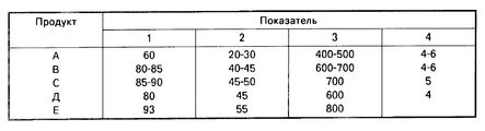
Применяемый продукт 13 сам оценивается с энергетической точки зрения, причем содержание воды в нем также меньше. Воздух, выходящий из реактора 16 и который извлекается первичным баллоном 24А, является горячим и влажным. Этот выходящий воздух проходит в любую термическую машину 50, например простой тепловой насос, с целью рекуперации из него, по меньшей мере, части энергии. Горячий воздух, такой как схематично представлено прерывистыми линиями на фиг.1, может быть использован для вдувания горячего и/или сухого воздуха в реактор 16 для предварительного нагрева продукта 13 или для другого любого применения и, с другой стороны, воды, которая собирается в бак 51 или сливается в водосток. Когда обрабатываемый продукт 10 складывается и спрессовывается, можно рекуперовать горячий и влажный воздух, который может быть обработан и использован известным способом. В том и в другом случае рекуперация горячего и влажного воздуха, и, следовательно, энергии осуществляется преимущественно без какого бы то ни было нарушения последующей обработки, а рекуперованная таким образом энергия преимущественно используется в течение того же самого процесса. Если применяется параллельная батарея реакторов 16, каждый из этих реакторов 16 преимущественно может соответствовать другому состоянию обрабатываемого продукта 10. Чтобы лучше проиллюстрировать возможности изобретения, в качестве неограничительных примеров приводятся результаты некоторого числа испытаний, проведенных на разных продуктах А, В, С, D и E. Эти испытания были проведены с помощью четырех реакторов объемом 100 м3 каждый, причем количества обработанных продуктов каждый раз в среднем составляли 40 т на испытание.The
The
В таблице последовательно занесены различные продукты А, В, С, D, E, а в вертикальных столбцах:
1 исходное содержание воды,
2 конечное содержание воды,
3 количество испарившейся воды, кг на тонну обработанного продукта, при имевших место, или нет, атмосферных осадках;
4 время обработки, в неделях, в реакторе.The various products A, B, C, D, E are sequentially listed in the table, and in the vertical columns:
1 initial water content,
2 final water content,
3 the amount of evaporated water, kg per ton of processed product, with or without atmospheric precipitation;
4 processing time, in weeks, in the reactor.
Обработанные продукты представляли собой:
A очистная грязь завода по изготовлению желатина, смешанная с сосновой корой;
В очистная грязь консервного завода, смешанная с сосновой корой;
С очистная грязь промышленной фармацевтической установки по обработке мака, смешанная с сосновой корой;
D побочные продукты промышленной установки, обрабатывающей отходы кожи, смешанные с сосновой корой;
Е побочные продукты промышленной установки для экстрагирования пектина из цитрусовых, смешанные с кукурузными отходами.Processed products were:
A gelatin plant treatment mud mixed with pine bark;
Into the canning sludge mixed with pine bark;
With treatment mud from an industrial pharmaceutical poppy processing plant mixed with pine bark;
D by-products of an industrial plant processing leather waste mixed with pine bark;
E by-products of an industrial plant for extracting pectin from citrus fruits mixed with corn wastes.
Для продуктов D и E дополнительная сушка горячим воздухом позволила снизить содержание воды до 37%
В варианте выполнения, представленном на фиг.10, реактор 16 образован из кузова с перфорированными каналами 25, которые он имеет в своих лонжеронах 58. Этот пример выполнения имеет преимущество непосредственной стандартизации и может быть использован в других конкретных применениях. Он обладает другим преимуществом, будучи модулируемым, не сложен в строительстве и минимально загрязняет среду, поскольку может быть легко перенесен с одного места пользования на другое, а также легко перекрыт при необходимости.For products D and E, additional drying with hot air reduced the water content to 37%
In the embodiment of FIG. 10, the
В варианте установки типа "кузов" можно предусмотреть осуществление циркуляции воздуха снизу вверх через обрабатываемый продукт либо посредством продувания снизу этого продукта, либо всасыванием его в верхней части, защищая, например, этот обрабатываемый продукт покрытием, которое размещается в конкретном случае на бункере. Можно также использовать средства информатики для программирования и/или регулирования. In a “body” type of installation, it is possible to provide for the circulation of air from the bottom up through the processed product, either by blowing from below this product or by suctioning it in the upper part, protecting, for example, this processed product with a coating that is placed in a particular case on the hopper. You can also use informatics for programming and / or regulation.
Claims (15)
Applications Claiming Priority (2)
| Application Number | Priority Date | Filing Date | Title |
|---|---|---|---|
| FR8901609 | 1989-02-08 | ||
| FR8901609A FR2642825B1 (en) | 1989-02-08 | 1989-02-08 | VENTILATION AND REGULATION PROCESS AND PLANT FOR THE TREATMENT, IN PARTICULAR OF BIOLOGICAL DEHYDRATION AND STABILIZATION, OF ANY WET AND FERMENTABLE TARGET ORGANIC PRODUCT |
Publications (1)
| Publication Number | Publication Date |
|---|---|
| RU2043983C1 true RU2043983C1 (en) | 1995-09-20 |
Family
ID=9378582
Family Applications (1)
| Application Number | Title | Priority Date | Filing Date |
|---|---|---|---|
| SU4743114/15A RU2043983C1 (en) | 1989-02-08 | 1990-02-07 | Installation for ventilation and regulation of moist and fermentable organic product |
Country Status (6)
| Country | Link |
|---|---|
| US (1) | US5628812A (en) |
| EP (1) | EP0391753A1 (en) |
| JP (1) | JPH02289480A (en) |
| DD (1) | DD297003A5 (en) |
| FR (1) | FR2642825B1 (en) |
| RU (1) | RU2043983C1 (en) |
Families Citing this family (10)
| Publication number | Priority date | Publication date | Assignee | Title |
|---|---|---|---|---|
| ES2113407T3 (en) * | 1991-11-08 | 1998-05-01 | Veluwse Afval Recycling B V | PROCEDURE AND DEVICE TO AEROBICALLY FERTILIZE ORGANIC MATERIAL. |
| FI962625A0 (en) * | 1995-11-01 | 1996-06-25 | Vapo Oy | Logistics for the production of tunnel composting and control of tunnel composting |
| FR2743803B1 (en) * | 1996-01-19 | 1998-03-27 | Tempe Maurice | METHOD FOR THE BIOLOGICAL DEGRADATION OF ORGANIC PRODUCTS, AND IMPLEMENTING PLANTS |
| FR2763585B1 (en) * | 1997-05-21 | 1999-08-06 | Lanvin | PROCESS FOR TREATING SLUDGE, FACILITIES OPERATING ACCORDING TO THIS PROCESS AND MATERIALS OBTAINED BY IMPLEMENTING THE PROCESS |
| FR2819504B1 (en) * | 2001-01-16 | 2003-06-13 | Lyonnaise Eaux Eclairage | COMPOSTING PLANT FOR SLUDGE FROM SEWAGE TREATMENT PLANTS |
| US6881370B2 (en) * | 2002-03-05 | 2005-04-19 | Karl R. Meyer | Method for fabricating a hard cover for an article |
| FR2839305B1 (en) * | 2002-05-03 | 2005-02-18 | Audit Conseil Efficacite Strat | MODULAR AND OPTIMIZED INSTALLATION FOR COMPOSTING ORGANIC MATERIALS |
| US7081147B2 (en) * | 2003-04-16 | 2006-07-25 | Philip John Giesy | Easy-to-turn compost bin |
| JP6383687B2 (en) * | 2015-03-20 | 2018-08-29 | 太平洋セメント株式会社 | Ventilation equipment and fuel conversion method for organic sludge |
| RU2695460C1 (en) * | 2019-01-22 | 2019-07-23 | Владимир Степанович Григорьев | Method for production of humus from vegetable wastes and device for its implementation |
Family Cites Families (20)
| Publication number | Priority date | Publication date | Assignee | Title |
|---|---|---|---|---|
| DE700737C (en) * | 1937-02-10 | 1940-12-31 | Eau Et Assainissement Anciens | Process and device for the production of fertilizers by fermenting household waste |
| GB676123A (en) * | 1950-01-24 | 1952-07-23 | Serck Radiators Ltd | Improvements relating to thermostats |
| GB886485A (en) * | 1960-09-14 | 1962-01-10 | Naturizer Co | Process of decomposing and stabilizing refuse |
| US3138448A (en) * | 1961-03-28 | 1964-06-23 | Schulze Karl Ludwig | Method for control of aerobic decomposition |
| GB1060461A (en) * | 1963-02-12 | 1967-03-01 | Simon Handling Eng Ltd | Improvements in bacteriological digesters for conversion of organic waste |
| US3285732A (en) * | 1963-12-05 | 1966-11-15 | Schulze Karl Ludwig | Continuous single-zone thermophilic phase composting process |
| FR1462221A (en) * | 1965-06-30 | 1966-04-15 | Automatic and hygienic process for the accelerated transformation of household waste into composts | |
| DE1582111B1 (en) * | 1966-02-05 | 1971-08-26 | Voith Muellex Gmbh | Device for supplying and removing gas or vaporous media in a compost pile set up on a sole area |
| JPS5437230B2 (en) * | 1972-06-02 | 1979-11-14 | ||
| DE2319081B1 (en) * | 1973-04-16 | 1973-12-06 | Voith-Müllex GmbH, 7920 Heidenheim | Dump plate - for composting plant |
| US3976245A (en) * | 1974-06-24 | 1976-08-24 | Cole James D | Automatic, temperature responsive damper assembly |
| FR2303776A1 (en) * | 1975-03-14 | 1976-10-08 | Kroczynski Patrice | Batch control instrument for compost fermentation - compares temp. and moisture readings with values from optimisation curve |
| DE2541070B2 (en) * | 1975-09-15 | 1980-03-06 | Gebrueder Weiss Kg, 6340 Dillenburg | Process for the continuous composting of organic waste and / or sewage sludge and device for carrying out the process |
| DE2729379A1 (en) * | 1976-07-07 | 1978-01-12 | Graefe Gernot | PROCESS AND PLANT FOR THE PRODUCTION OF HIGH QUALITY DUENGER |
| US4339265A (en) * | 1980-02-27 | 1982-07-13 | Veda, Inc. | Sewage treatment method and apparatus |
| FR2482084B1 (en) * | 1980-05-08 | 1985-07-12 | Weynandt Jean | COMPOST FROM ORGANIC WASTE, PROCESS FOR OBTAINING SAME, AND INSTALLATION FOR IMPLEMENTING THE PROCESS |
| US4483704A (en) * | 1980-08-07 | 1984-11-20 | Easter Ii James M | Method for composting sludge |
| IT1156543B (en) * | 1982-11-05 | 1987-02-04 | Ipla Ist Piante Legno Ambiente | PROCEDURE FOR THE MANUFACTURE OF AN ORGANIC AND FERTILIZER AGRICULTURAL FERTILIZER OBTAINED BY SUCH PROCEDURE |
| US4521517A (en) * | 1983-04-25 | 1985-06-04 | Gauthier, Alvarado & Associates, Inc. | Compost aeration system |
| DE3401889A1 (en) * | 1984-01-20 | 1985-07-25 | Gebrüder Bühler AG, Uzwil | Process and apparatus for converting refuse materials into compost |
-
1989
- 1989-02-08 FR FR8901609A patent/FR2642825B1/en not_active Expired - Lifetime
-
1990
- 1990-02-07 EP EP19900400338 patent/EP0391753A1/en not_active Withdrawn
- 1990-02-07 RU SU4743114/15A patent/RU2043983C1/en not_active IP Right Cessation
- 1990-02-07 DD DD90337659A patent/DD297003A5/en not_active IP Right Cessation
- 1990-02-08 JP JP2029371A patent/JPH02289480A/en active Pending
- 1990-02-08 US US07/476,784 patent/US5628812A/en not_active Expired - Fee Related
Non-Patent Citations (2)
| Title |
|---|
| 1. Патент Франции N 2523953, кл. C 05F 9/04, 1983. * |
| 2. Патент Франции N 2519972, кл. C 05F 1/02, 1983. * |
Also Published As
| Publication number | Publication date |
|---|---|
| FR2642825A1 (en) | 1990-08-10 |
| EP0391753A1 (en) | 1990-10-10 |
| FR2642825B1 (en) | 1994-08-12 |
| US5628812A (en) | 1997-05-13 |
| JPH02289480A (en) | 1990-11-29 |
| DD297003A5 (en) | 1991-12-19 |
Similar Documents
| Publication | Publication Date | Title |
|---|---|---|
| US2178818A (en) | Bacteriological digester for conversion of organic waste | |
| US4208279A (en) | Method and apparatus for processing animal waste | |
| RU2043983C1 (en) | Installation for ventilation and regulation of moist and fermentable organic product | |
| CA2671108C (en) | Method and apparatus for drying organic material | |
| DE2723581A1 (en) | METHOD FOR AEROBIC ROTATION OF ORGANIC SOLIDS AND DEVICE FOR CARRYING OUT THE METHOD | |
| EP0999194A2 (en) | Waste treatment system | |
| EP1980546A2 (en) | Process and system for the production of energy and composted material from agricultural waste containing cellulose | |
| US4956002A (en) | Method for the composting of organic materials | |
| EP1555255A1 (en) | Device for utilization of organic waste material particularly animal by - products | |
| CN106220254A (en) | Modern pasture, cold ground excrement dirt integrated conduct method | |
| US20080022739A1 (en) | Vertical composter with leachate retention system | |
| DE19947339A1 (en) | Agricultural methane generator reactor has sub-surface inlet accelerating fermentation | |
| US6672251B1 (en) | Method for drying slurry, rinse water and industrial effluent and/or residues | |
| Basnayake | Municipal solid waste (msw) for organic agriculture | |
| KR101939626B1 (en) | Vegetative soil produced by recycling system of organic waste and construction method of inclined plane using the same | |
| KR101247668B1 (en) | The composting system of livestock excreta by the fly larva | |
| JP3706097B2 (en) | Organic waste fermentation treatment system | |
| EP0707559B1 (en) | Plant and process for composting organic material | |
| RU2244698C1 (en) | Apparatus and method for composting with the use of vermiculite culture | |
| US1730489A (en) | Process of disposal of sewage or other waste organic matter | |
| Wellinger et al. | New systems for the digestion of solid wastes | |
| RU2092469C1 (en) | Method and installation for preparing organic fertilizer from wastes | |
| Duvoort-van Engers et al. | State of the Art” on Sludge Composting | |
| Caetano | Composting | |
| DE3644710A1 (en) | Fermenting chamber process for the fermentation of biological waste material |
Legal Events
| Date | Code | Title | Description |
|---|---|---|---|
| MM4A | The patent is invalid due to non-payment of fees |
Effective date: 20030208 |