RU121216U1 - ELECTRIC ACTUATOR ARROW TYPE JV ON THE BASIS OF A NON-CONTACT AUTOMATIC SWITCH - Google Patents
ELECTRIC ACTUATOR ARROW TYPE JV ON THE BASIS OF A NON-CONTACT AUTOMATIC SWITCH Download PDFInfo
- Publication number
- RU121216U1 RU121216U1 RU2012124211/11U RU2012124211U RU121216U1 RU 121216 U1 RU121216 U1 RU 121216U1 RU 2012124211/11 U RU2012124211/11 U RU 2012124211/11U RU 2012124211 U RU2012124211 U RU 2012124211U RU 121216 U1 RU121216 U1 RU 121216U1
- Authority
- RU
- Russia
- Prior art keywords
- switch
- contacts
- control
- housing
- reed
- Prior art date
Links
Landscapes
- Train Traffic Observation, Control, And Security (AREA)
Abstract
1. Электропривод стрелочный, содержащий корпус с крышкой, в котором смонтирован ряд агрегатов и механизмов, в том числе электродвигатель, автопереключатель, кинематическая группа, обеспечивающая перемещение шибера и контрольных линеек, отличающийся тем, что автопереключатель выполнен бесконтактным, содержащим герконовые датчики положения с магнитными контактами, при этом каждый из датчиков положения управляется роликовым поводком контрольного рычага, и связан с соответствующим одним из двух переключающих рычагов, взаимодействующих с профилем диска главного вала шиберной шестерни. ! 2. Электропривод стрелочный по п.1, отличающийся тем, что корпус герконового датчика положения содержит неподвижный статор с попарно срабатывающими герметическими контактами и вращаемый ротор с диаметрально расположенными постоянными магнитами, управляемый контрольным рычагом. ! 3. Электропривод стрелочный по п.2, отличающийся тем, что неподвижный статор содержит четыре герметичных контакта, а вращаемый ротор - два магнита. 1. Electric switch actuator, containing a housing with a cover, in which a number of units and mechanisms are mounted, including an electric motor, an autoswitch, a kinematic group that ensures the movement of the gate and control rulers, characterized in that the autoswitch is made contactless, containing reed position sensors with magnetic contacts , wherein each of the position sensors is controlled by a roller drive of the control lever, and is associated with the corresponding one of two switching levers interacting with the profile of the disk of the main shaft of the gate gear. ! 2. Electric switch actuator according to claim 1, characterized in that the housing of the reed position sensor contains a stationary stator with pairwise actuated hermetic contacts and a rotatable rotor with diametrically located permanent magnets, controlled by a control lever. ! 3. Electric switch actuator according to claim 2, characterized in that the stationary stator contains four sealed contacts, and the rotating rotor contains two magnets.
Description
Полезная модель относится к стрелочным электроприводам железнодорожной автоматики и телемеханики, которые могут быть использованы для установки на гарнитуре у железнодорожных стрелок с правой или левой стороны стрелочного перевода и управления с поста электрической централизации, и предназначены для перевода в повторно-кратковременном режиме, запирания и контроля положения в непрерывном режиме стрелок с нераздельным ходом остряков.The utility model relates to turnout electric drives of railway automation and telemechanics, which can be used for mounting on a headset near railroad switches on the right or left side of the turnout switch and control from the electric centralization station, and are intended for intermittent translation, locking and position monitoring in continuous mode the shooter with the indivisible course of wits.
Известно устройство - электропривод стрелочный невзрезной бесконтактный типа СПГБ-4Б (Сайт http://edu.dvgups.ru/METDOC/GDTRAN/YAT/AT/ST_SYS_AT/METOD/STREL_ELEKTROPR/Pel_4.htm.) [1]. Отличие устройства в том, что оно содержит трансформаторные бесконтактные датчики и более скоростной электродвигатель. Однако область применения известного устройства ограничена установкой на стрелочных переводах сортировочных горок, а также включением в девятипроводную схему управления для скоростного перевода стрелок, и не предназначено для работы на стрелочных переводах путей с пяти- и двухпроводной схемами подключения к централизованному управлению.A device is known - an electric non-cutting arrow non-contact type SPGB-4B (Website http://edu.dvgups.ru/METDOC/GDTRAN/YAT/AT/ST_SYS_AT/METOD/STREL_ELEKTROPR/Pel_4.htm.) [1]. The difference between the device is that it contains transformer proximity sensors and a faster electric motor. However, the scope of the known device is limited to the installation on the turnouts of sorting slides, as well as the inclusion of a nine-wire control circuit for high-speed turnouts, and is not intended to work on turnouts of tracks with five- and two-wire circuits for connecting to centralized control.
Известно устройство - электропривод стрелочный с внутренним замыканием типа СП-6М (Армавирский электромеханический завод, филиал ОАО «ЭЛТЕЗА». Сайт http://www.100best.ru/Catalogue/Products/259700/) [2], управляемое с поста электрической централизации, для перевода в повторно-кратковременном режиме, запирания и контроля положения в непрерывном режиме стрелок с нераздельным ходом остряков, которое содержит корпус 1 с крышкой, в корпусе смонтирован ряд агрегатов и механизмов, в том числе электродвигатель 2, автопереключатель 3, кинематическая группа, обеспечивающая перемещение шибера и контрольных линеек, см. чертеж ЮКЛЯ.303341.007 ТУ 32 ЦШ 2104-2002 (фиг.1).A device is known - electric switch with internal circuit type SP-6M (Armavir Electromechanical Plant, a branch of OJSC ELTEZA. Website http://www.100best.ru/Catalogue/Products/259700/) [2], controlled from the post of electric centralization , for translation in intermittent mode, locking and monitoring the position in continuous mode of the shooter with an indivisible move of the wit, which contains a housing 1 with a cover, a number of units and mechanisms are mounted in the housing, including an electric motor 2, a circuit breaker 3, a kinematic group, which provides I move the gate and control rulers, see the drawing YUKLYA.303341.007 TU 32 TsSh 2104-2002 (Fig. 1).
Взаимодействие главного вала с автопереключателем осуществляется посредством пары трения ось-ролик переключающего рычага. Автопереключатель состоит из неподвижной контактной колодки и колодки с ножами, образующие замыкание либо размыкание цепи электрического питания электродвигателя.The interaction of the main shaft with the auto-switch is carried out by means of an axis-roller friction pair of the switching lever. A circuit breaker consists of a fixed terminal block and a block with knives, forming a short circuit or opening of the electric motor power circuit.
Электропривод типа СП-6М позволяет осуществить перевод, запирание и контроль положения в непрерывном режиме стрелок с нераздельным ходом остряков.The electric drive of the type SP-6M allows you to translate, lock and control the position in the continuous mode of the shooter with the inseparable movement of the wits.
Недостаток электропривода типа СП-6М заключается в том, что применяемый в его конструкции автопереключатель 3 открытого типа с колодками контактными 4 и колодками ножевыми 5 (фиг.2) отличается низкой надежностью и большим количеством отказов в работе, такими как: излом, индевение или обледенение, подгар или нарушение регулировки контактов автопереключателя, что приводит к применению различных защитных мер (специальных смазок, обогрева, защиты контактной зоны, нанесения специальных насечек на ножах и т.д.).The disadvantage of the type SP-6M electric drive is that the open switch 3 used in its design with contact blocks 4 and knife blocks 5 (Fig. 2) is characterized by low reliability and a large number of failures in operation, such as: kink, frosting or icing , a burnout or a violation of the adjustment of the contacts of the auto-switch, which leads to the use of various protective measures (special lubricants, heating, protection of the contact zone, applying special notches on knives, etc.)
Электропривод типа СП-6М по совокупности признаков принят в качестве наиболее близкого аналога.The electric drive type SP-6M in terms of features accepted as the closest analogue.
Указанные недостатки устранены автопереключателем бесконтактного типа на основе герконовых датчиков положения с магнитными контактами.These disadvantages are eliminated by a contactless type auto-switch based on reed position sensors with magnetic contacts.
Технический результат, достигаемый настоящей полезной моделью, заключается в возможности получения малообслуживаемой, стабильной и долговременной работы электропривода стрелочного по переводу, запиранию и контролю положения в непрерывном режиме стрелок с нераздельным ходом остряков, а также увеличению срока межремонтного периода и значительному уменьшению количества отказов электроприводов и связанных с этим простоев на железной дороге.The technical result achieved by this utility model consists in the possibility of obtaining low-maintenance, stable and long-term operation of the switch electric drive for translating, locking and monitoring the position in continuous operation of the switch with inseparable movement of witters, as well as increasing the overhaul period and significantly reducing the number of failures of electric drives and associated with this downtime on the railway.
Технический результат достигается тем, что в электроприводе стрелочном, содержащем корпус с крышкой, в котором смонтирован ряд агрегатов и механизмов, в том числе электродвигатель, автопереключатель, кинематическая группа, обеспечивающая перемещение шибера и контрольных линеек, согласно полезной модели автопереключатель выполнен бесконтактным, содержащим два герконовых датчика положения с магнитными контактами, при этом каждый из датчиков положения управляется роликовым поводком контрольного рычага, и связан с соответствующим одним из двух переключающих рычагов, взаимодействующих с профилем диска главного вала шиберной шестерни.The technical result is achieved by the fact that in a turnout electric actuator containing a housing with a cover, in which a number of units and mechanisms are mounted, including an electric motor, an automatic switch, a kinematic group that provides movement of the gate and control rulers, according to a utility model, the automatic switch is made non-contact, containing two reed switches a position sensor with magnetic contacts, wherein each of the position sensors is controlled by a roller leash of the control lever, and is connected with the corresponding one m of two switching levers interacting with the disk profile of the main shaft of the vane gear.
При этом корпус герконового датчика положения содержит статор с попарно срабатывающими герметическими контактами, и ротор, с диаметрально расположенными постоянными магнитами, управляемый контрольным рычагом.The housing of the reed switch position sensor contains a stator with pairwise actuated hermetic contacts, and a rotor with diametrically arranged permanent magnets, controlled by a control lever.
При этом неподвижный статор содержит четыре герметичных контакта, а вращаемый ротор - два магнита.In this case, the fixed stator contains four tight contacts, and the rotated rotor contains two magnets.
Заявляемая полезная модель поясняется следующими графическими материалами.The inventive utility model is illustrated by the following graphic materials.
Фиг.1 - Общий вид электропривода СП-6М - наиболее близкого аналога.Figure 1 - General view of the electric drive SP-6M - the closest analogue.
Фиг.2 - Схема автопереключателя электропривода СП-6М.Figure 2 - Diagram of the auto-switch electric drive SP-6M.
Фиг.3 - Общий вид заявляемого электропривода на базе бесконтактного автопереключателя.Figure 3 - General view of the inventive electric drive based on a proximity contact switch.
Фиг.4 - Схема бесконтактного автопереключателя с герконовыми датчиками положения.Figure 4 - Diagram of a contactless auto switch with reed position sensors.
Фиг.5 - Схема общего вида герконового датчика положения с магнитными контактами.5 is a diagram of a General view of a reed switch position sensor with magnetic contacts.
Фиг.6. - Схема герконового датчика положения с магнитными контактами, вид А на фиг.5.6. - Diagram of a reed switch position sensor with magnetic contacts, view A in FIG. 5.
Фиг.7 - Кинематическая схема и алгоритм работы автопереключателя с герконовыми датчиками положения.7 - Kinematic diagram and algorithm of the operation of the switch with reed position sensors.
Перечень позиций на фигурах.The list of positions in the figures.
1 - корпус,1 - housing
2 - электродвигатель,2 - electric motor,
3 - автопереключатель,3 - auto switch,
4 - колодки контактные,4 - contact pads,
5 - колодки ножевые,5 - knife pads,
6 - кулачковая муфта,6 - cam clutch,
7 - редуктор,7 - gear
8 - основание автопереключателя,8 - the basis of the auto switch,
9 - контрольные рычаги,9 - control levers,
10 - ролик контрольного рычага,10 - roller control lever
11 - герконовые датчики положения,11 - reed position sensors,
12 - шибер;12 - gate;
13 - контрольные линейки;13 - control rulers;
14, 15 - герметичные контакты (герконы),14, 15 - sealed contacts (reed switches),
16 - статор,16 - stator
17 - разъем,17 - connector
18 - поводок,18 - leash
19 - ротор,19 - rotor
20 - магниты,20 - magnets,
21 - корпус датчика положения,21 - the housing of the position sensor,
22 - главный вал,22 - the main shaft,
23 - пружины растяжения,23 - tension springs,
24 - диск главного вала,24 - a disk of the main shaft,
25, 28 - переключающие рычаги,25, 28 - shifting levers,
26 - зуб контрольного рычага,26 - tooth control lever,
27 - ролик переключающего рычага 25,27 - roller switching lever 25,
29 - ролик переключающего рычага 28.29 - roller shift lever 28.
Заявляемый электропривод стрелочный типа СП (фиг.3…7) содержит:The inventive switch arrow type joint venture (Fig.3 ... 7) contains:
- корпус 1 с крышкой, запираемой изнутри специальным замком; в корпусе смонтирован ряд агрегатов и механизмов, в том числе:- housing 1 with a lid, locked from the inside with a special lock; a number of units and mechanisms are mounted in the housing, including:
- электродвигатель 2, предающий вращение через кулачковую муфту 6 на редуктор 7, состоящий из фрикционной муфты и зубчатых передач;- an electric motor 2, which rotates through a cam clutch 6 to a gearbox 7, consisting of a friction clutch and gears;
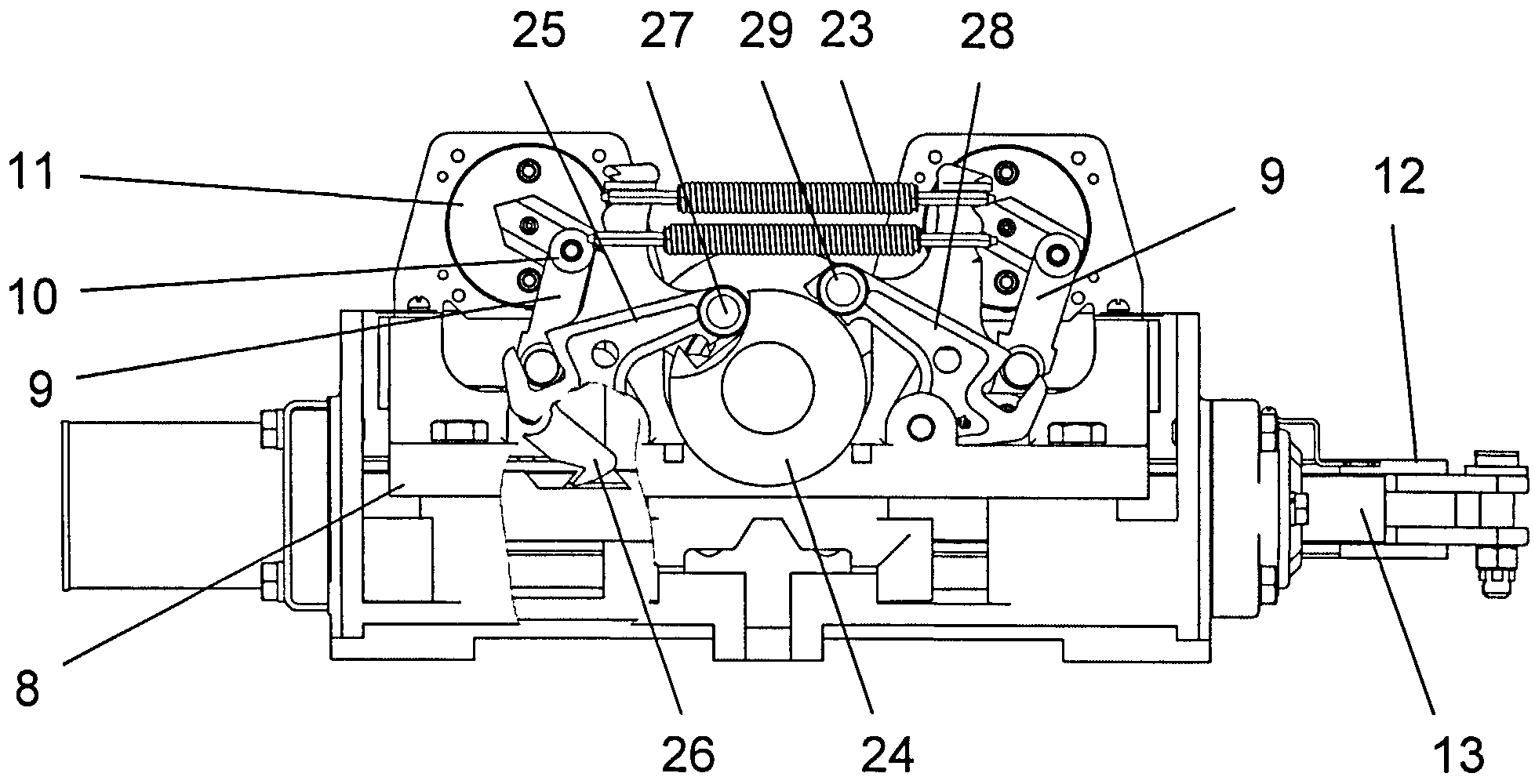
- автопереключатель 3 (фиг.4), содержащий чугунное основание 8, на котором установлены свободно поворачиваемые стальные контрольные рычаги 9, каждый из которых содержит запорный зуб 26 для фиксации в пазах контрольных линеек 13 и ролик 10, для управления герконовыми датчиками положения 11, а также шибер 12 и контрольные линейки 13;- auto-switch 3 (figure 4), containing a cast-iron base 8, on which are freely rotatable steel control levers 9, each of which contains a locking tooth 26 for fixing in the grooves of the control rulers 13 and the roller 10, for controlling reed switch position sensors 11, and also the gate 12 and the control line 13;
- кинематическую группу, обеспечивающую перемещение шибера 12 и контрольных линеек 13, содержащую две параллельных пружины растяжения 23, переключающие рычаги 25 и 28, ролики 27 и 29 переключающих рычагов 25 и 28, соответственно, профильный диск 24 главного вала 22;- a kinematic group that provides movement of the gate 12 and the control rulers 13, containing two parallel tension springs 23, the switching levers 25 and 28, the rollers 27 and 29 of the switching levers 25 and 28, respectively, a profile disk 24 of the main shaft 22;
- герконовые датчики положения 11 с магнитными контактами (фиг.5…7), выполненные в металлическом корпусе 21. Корпус герконового датчика положения (фиг.6) содержит неподвижный статор 16, в котором попарно установлены четыре герметичных контакта 14 и 15, которые проводниками соединены с разъемом 17, и отклоняемый ротор 19, управляемый контрольным рычагом 9. Во вращающемся роторе 19, который расположен на валу поводка 18, помещены магниты 20. Ротор с магнитами, вращаясь под действием контрольных рычагов 9 автопереключателя, действует на герметичные контакты (герконы) 14 или 15, замыкая их своим магнитным полем и занимая при этом различные варианты фиксированных (фиг.7) положений (при соответствующей ситуации на стрелочном переводе): а) контроль переведенного положения и контроль начального положения; б) состояние потери контроля прижатия остряков рельса; в) контроль начального положения и контроль переведенного положения; г) взрез стрелочного перевода.- reed switch position sensors 11 with magnetic contacts (Fig.5 ... 7), made in a metal housing 21. The housing of the reed switch position sensor (Fig.6) contains a fixed stator 16, in which four sealed contacts 14 and 15 are connected in pairs, which are connected by conductors with a connector 17, and a deflectable rotor 19, controlled by the control lever 9. In the rotating rotor 19, which is located on the shaft of the leash 18, magnets 20 are placed. The rotor with magnets, rotating under the action of the control levers 9 of the auto switch, acts on tight contacts you (reed switches) 14 or 15, closing them with your own magnetic field and occupying various variants of fixed (Fig. 7) positions (in the corresponding situation on the turnout): a) control of the translated position and control of the initial position; b) the state of loss of control of pressing wit rail; c) control of the initial position and control of the translated position; d) incision of the turnout switch.
Герконовый датчик положения с магнитными контактами является изделием универсальным и взаимозаменяемым, алгоритм его работы не зависит от местоположения на автопереключателе и определяется распайкой проводников соединительного кабеля в разъемах и положением контрольных линеек электропривода, что исключает возможность перепутывания датчиков. Герконовые датчики положения допускаются для использования во всех климатических зонах мира. Предполагаемое количество рабочих циклов датчиков - 106 циклов.The reed switch with magnetic contacts is a universal and interchangeable product, its operation algorithm does not depend on the location on the circuit breaker and is determined by the wiring of the conductors of the connecting cable in the connectors and the position of the control rulers of the electric drive, which eliminates the possibility of entanglement of the sensors. Reed position sensors are approved for use in all climatic zones of the world. Estimated number of sensor operating cycles is 10 6 cycles.
Электропривод стрелочный типа СП может быть снабжен электродвигателями различных исполнений по типу электрического тока, номинальному напряжению.Switch electric drive type SP can be equipped with electric motors of various designs according to the type of electric current, rated voltage.
Возможность осуществления полезной модели иллюстрируется примером конкретного выполнения электропривода стрелочного типа СП на базе бесконтактного автопереключателя с применением герконовых датчиков положения, общий вид и схема которого представлены на фиг.3 и 4.The feasibility of the utility model is illustrated by an example of a specific embodiment of an electric switch arrow type SP based on a non-contact auto-switch using reed switch position sensors, a general view and diagram of which are shown in FIGS. 3 and 4.
Корпус 1 электропривода представляет собой чугунную отливку прямоугольной формы, по двум противоположным сторонам которой в местах выхода рабочего шибера 12 и контрольных линеек 13, для предохранения от проникновения внутрь его брызг воды и песка устанавливаются уплотнения. Закрывается электропривод сварной стальной крышкой, имеющей по бортам уплотнения. Запирается электропривод изнутри специальным замком.The housing 1 of the electric drive is a cast-iron casting of a rectangular shape, on two opposite sides of which at the exit points of the working gate 12 and the control rulers 13, seals are installed to prevent water and sand from penetrating inside it. The electric drive is closed by a welded steel cover with sealing on the sides. The electric drive is locked from the inside with a special lock.
В корпусе 1 установлен электродвигатель 2, на конце вала которого установлена специальная кулачковая муфта 6, которая одновременно соединяется с вал-шестерней редуктора 7. Редуктор 7 со встроенной фрикционной муфтой представляет собой отдельный узел, монтируемый в корпусе электропривода.An electric motor 2 is installed in the housing 1, at the end of the shaft of which a special cam clutch 6 is installed, which is simultaneously connected to the gear shaft of the gearbox 7. The gearbox 7 with an integrated friction clutch is a separate assembly mounted in the drive housing.
Автопереключатель 3 состоит из чугунного основания 8, на котором установлены два герконовых датчика положения 11 (фиг.4). К датчикам 11 также подсоединены электрические жгуты, которые не показаны на чертеже. На осях в чугунном основании помещаются свободно поворачиваемые стальные контрольные рычаги 9 с зубьями 26 и роликами 10. Под действием двух пружин растяжения 23, закрепленных параллельно на переключающих рычагах 25 и 28, контрольный рычаг 9 своим роликом 10 отклоняет ротор 19 (фиг.6) герконового датчика положения 11, тем самым замыкая диагонально расположенные герметичные контакты 14 (фиг.6, 7), контролируя при этом положение стрелочного перевода, которое соответствует состоянию а) (фиг.7). При этом положении ролик 27 переключающего рычага 25 западает в вырез диска 24 главного вала 22, а ролик 29 переключающего рычага 28 находится на поверхности диска 30 главного вала 22. Контрольные рычаги 9 обеспечивают потерю контроля положения стрелки при сближении остряков вследствие деформации тяг от ударов и т.д. Контрольные линейки 13 имеют вырезы, в которые попеременно при ходе их вместе с остряками стрелок западают зубья 26 контрольных рычагов 9.The switch 3 consists of a cast iron base 8, on which are installed two reed switch position sensors 11 (figure 4). To the sensors 11 are also connected electrical harnesses, which are not shown in the drawing. On the axes in a cast-iron base, freely rotatable steel control levers 9 with teeth 26 and rollers 10 are placed. Under the action of two tension springs 23 mounted in parallel on the switching levers 25 and 28, the control lever 9 deflects the reed rotor 19 (6) with its roller 10 position sensor 11, thereby closing the diagonally located sealed contacts 14 (Fig.6, 7), while controlling the position of the switch, which corresponds to state a ) (Fig.7). In this position, the roller 27 of the switching lever 25 falls into the cutout of the disk 24 of the main shaft 22, and the roller 29 of the switching lever 28 is located on the surface of the disk 30 of the main shaft 22. The control levers 9 provide loss of control of the position of the arrow when approaching wit due to deformation of rods from impacts and t .d. The control rulers 13 have cutouts in which, alternately during the course of their movement, along with the sharp points of the arrows, the teeth 26 of the control levers 9 fall.
Работа электропривода стрелочного типа СП на базе бесконтактного автопереключателя с применением герконовых датчиков положения.The operation of an electric drive of a switch type SP based on a proximity contact switch using reed switch sensors.
Вал электродвигателя, вращаясь через муфту и систему механической передачи редуктора, приводит во вращение зубчатое колесо с упором, которое выжимает ролик одного из переключающих рычагов, например, ролик 27 переключающего рычага 25, и выводит конец этого рычага из выреза диска 24 главного вала.The electric motor shaft, rotating through the clutch and the mechanical transmission system of the gearbox, rotates the gear with an emphasis, which squeezes the roller of one of the switching levers, for example, the roller 27 of the switching lever 25, and outputs the end of this lever from the cutout of the disk 24 of the main shaft.
Одновременно с этим переключающий рычаг 25 переключает через ролик 27 контрольный рычаг 9 с зубом 26 и роликом 10 из контрольного положения в рабочее положение. Под действием двух пружин растяжения 23, закрепленных параллельно на переключающих рычагах 25 и 28, контрольный рычаг 9 своим роликом 10 отклоняет поводки 18 ротора 19 левого и правого герконовых датчика положения 11, тем самым замыкая попарно расположенные по диагонали герметичные контакты 14 (фиг.6, 7), передавая на пост ЭЦ сигнал о рабочем состоянии привода и контролируя переведенное положение и начальное положение остряков стрелочного перевода.At the same time, the switching lever 25 switches through the roller 27 the control lever 9 with the tooth 26 and the roller 10 from the control position to the working position. Under the action of two tension springs 23 mounted in parallel on the switching levers 25 and 28, the control lever 9 with its roller 10 deflects the leads 18 of the rotor 19 of the left and right reed position sensors 11, thereby closing the diagonally sealed contacts 14 (Fig. 6, 7) by transmitting to the EC post a signal about the operating state of the drive and controlling the translated position and the initial position of the switch points.
После поворота зубчатое колесо с упором вращает диск 24 главного вала 22 шиберной шестерни.After rotation, the gear rotates the disk 24 of the main shaft 22 of the vane gear with emphasis.
Далее, как в прототипе-электроприводе стрелочном типа СП-6М, в начале вращения главного вала шиберной шестерни один из запорных зубьев шестерни отпирает запорный зуб рабочего шибера со стороны прижатого остряка и профилем эвольвенты запорного зуба шестерни заставляет перемещаться рабочий шибер, одновременно входя в зацепление с рабочими зубьями шестерни в том же направлении.Further, as in the prototype electric drive switch type SP-6M, at the beginning of the rotation of the main shaft of the slide gear one of the locking teeth of the gear unlocks the locking tooth of the working gate from the side of the pressed pin and the involute profile of the locking tooth of the gear makes the working gate move, while it engages with working gear teeth in the same direction.
К концу перевода стрелки рабочий шибер 12 останавливается, и переключающий рычаг 25 под действием двух параллельных пружин растяжения 23 западает в вырез диска 24 главного вала 22 шиберной шестерни. Одновременно с этим контрольный рычаг 9 с зубом 26 и роликом 10 под действием переключающего рычага 25 переключается и замыкает противоположно расположенную пару герметичных контактов 15 левого и правого герконовых датчиков 11, передавая на пост ЭЦ сигнал о состоянии привода и размыкая при этом герметичные контакты 14. В конце перевода другой запорный зуб шестерни запирает второй запорный зуб рабочего шибера, но уже со стороны второго прижатого остряка.By the end of the translation of the arrow, the working gate 12 stops, and the switching lever 25 under the action of two parallel tension springs 23 falls into the cutout of the disk 24 of the main shaft 22 of the gate gear. At the same time, the control lever 9 with the tooth 26 and the roller 10 under the action of the switching lever 25 switches and closes the oppositely located pair of sealed contacts 15 of the left and right reed sensors 11, transmitting a signal about the drive status to the EC post and opening the sealed contacts 14. V At the end of the translation, another locking tooth of the gear locks the second locking tooth of the working gate, but already from the side of the second pressed wit.
Контрольные линейки служат для контроля положения прижатого остряка и достаточного отведения другого от рамного рельса.The control rulers are used to control the position of the pressed wit and sufficient abduction of the other from the frame rail.
Простая и надежная конструкция бесконтактных герконовых датчиков 11 защищена от влияния электромагнитных помех, индевения и других негативных факторов, которые укорачивают жизненный цикл автопереключателей ныне существующих известных устройств для стрелочных переводов. Это позволит увеличить срок службы и сделать конструкцию электропривода более технологичной.The simple and reliable design of the contactless reed switches 11 is protected from electromagnetic interference, indexing and other negative factors that shorten the life cycle of the current switches of the well-known switch devices. This will increase the service life and make the design of the drive more technological.
Заявляемый электропривод стрелочный типа СП на базе бесконтактного автопереключателя с использованием герконовых датчиков положения позволяет достичь стабильной и долговременной работы электропривода стрелочного по переводу, запиранию и контролю положения в непрерывном режиме стрелок с нераздельным ходом остряков.The inventive switch actuator type SP based on a proximity contact switch using reed switch position sensors allows to achieve stable and long-term operation of the switch actuator for translation, locking and position control in continuous operation of the shooter with inseparable movement of wits.
ИСТОЧНИКИ ИНФОРМАЦИИ.INFORMATION SOURCES.
1. ГОРОЧНЫЕ СТРЕЛОЧНЫЕ ЭЛЕКТРОПРИВОДЫ. Сайт http://edu.dvgups.ru/METDOC/GDTRAN/YAT/AT/ST_SYS_AT/METOD/STREL_ELEKTROPR/Pel_4.htm.1. MOUNTAIN ARROW ELECTRIC DRIVES. Website http://edu.dvgups.ru/METDOC/GDTRAN/YAT/AT/ST_SYS_AT/METOD/STREL_ELEKTROPR/Pel_4.htm.
2. Электропривод стрелочный с внутренним замыканием типа СП-6М. Армавирский электромеханический завод, филиал ОАО "Российские железные дороги". Сайт http://www.100best.ru/Catalogue/Products/259700/) - наиболее близкий аналог.2. Electric switch arrow with internal circuit type SP-6M. Armavir Electromechanical Plant, a branch of Russian Railways. The site http://www.100best.ru/Catalogue/Products/259700/) is the closest analogue.
Claims (3)
Priority Applications (1)
| Application Number | Priority Date | Filing Date | Title |
|---|---|---|---|
| RU2012124211/11U RU121216U1 (en) | 2012-06-09 | 2012-06-09 | ELECTRIC ACTUATOR ARROW TYPE JV ON THE BASIS OF A NON-CONTACT AUTOMATIC SWITCH |
Applications Claiming Priority (1)
| Application Number | Priority Date | Filing Date | Title |
|---|---|---|---|
| RU2012124211/11U RU121216U1 (en) | 2012-06-09 | 2012-06-09 | ELECTRIC ACTUATOR ARROW TYPE JV ON THE BASIS OF A NON-CONTACT AUTOMATIC SWITCH |
Publications (1)
| Publication Number | Publication Date |
|---|---|
| RU121216U1 true RU121216U1 (en) | 2012-10-20 |
Family
ID=47145658
Family Applications (1)
| Application Number | Title | Priority Date | Filing Date |
|---|---|---|---|
| RU2012124211/11U RU121216U1 (en) | 2012-06-09 | 2012-06-09 | ELECTRIC ACTUATOR ARROW TYPE JV ON THE BASIS OF A NON-CONTACT AUTOMATIC SWITCH |
Country Status (1)
| Country | Link |
|---|---|
| RU (1) | RU121216U1 (en) |
Cited By (3)
| Publication number | Priority date | Publication date | Assignee | Title |
|---|---|---|---|---|
| RU189880U1 (en) * | 2018-12-28 | 2019-06-07 | Открытое акционерное общество "Объединенные электротехнические заводы" (ОАО "ЭЛТЕЗА") | CONTROL MODULE OF POSITION OF A SHARK OR HEART OF A CROSSWAY WITH A CONTINUOUS ROLLING SURFACE |
| RU194811U1 (en) * | 2019-10-30 | 2019-12-24 | Открытое акционерное общество "Объединенные электротехнические заводы" | Switch electric drive |
| RU194948U1 (en) * | 2019-11-15 | 2020-01-09 | Открытое акционерное общество "Объединенные электротехнические заводы" | Slide switch electric drive |
-
2012
- 2012-06-09 RU RU2012124211/11U patent/RU121216U1/en not_active IP Right Cessation
Cited By (3)
| Publication number | Priority date | Publication date | Assignee | Title |
|---|---|---|---|---|
| RU189880U1 (en) * | 2018-12-28 | 2019-06-07 | Открытое акционерное общество "Объединенные электротехнические заводы" (ОАО "ЭЛТЕЗА") | CONTROL MODULE OF POSITION OF A SHARK OR HEART OF A CROSSWAY WITH A CONTINUOUS ROLLING SURFACE |
| RU194811U1 (en) * | 2019-10-30 | 2019-12-24 | Открытое акционерное общество "Объединенные электротехнические заводы" | Switch electric drive |
| RU194948U1 (en) * | 2019-11-15 | 2020-01-09 | Открытое акционерное общество "Объединенные электротехнические заводы" | Slide switch electric drive |
Similar Documents
| Publication | Publication Date | Title |
|---|---|---|
| RU121216U1 (en) | ELECTRIC ACTUATOR ARROW TYPE JV ON THE BASIS OF A NON-CONTACT AUTOMATIC SWITCH | |
| CN104681365A (en) | Circuit breaker and closing drive device thereof | |
| CN110853983A (en) | Magnetic latching relay for power electronic equipment | |
| CN200941536Y (en) | Three-station operator for gaseous insulated metallic packed switching gear | |
| RU164932U1 (en) | ELECTRIC DRIVE ARROW ON THE BASIS OF SP-10 FOR METRO | |
| RU194811U1 (en) | Switch electric drive | |
| RU111714U1 (en) | DEVICE OF ELECTROMAGNETIC LOCKING OF SWITCHING APPLIANCES | |
| US2190682A (en) | Direction of rotation responsive switch | |
| CN203895824U (en) | Hand-cranking drawer push-in interlocking mechanism | |
| RU220097U1 (en) | ELECTRIC DRIVE TYPE SP-20 | |
| RU2408488C2 (en) | Method to control joint between switch blade and rack bar, fit between rack bar and stock rail, and device to this end | |
| RU194948U1 (en) | Slide switch electric drive | |
| RU142614U1 (en) | ARROW MOUNTAIN PNEUMATIC DRIVE (OPTIONS) | |
| RU2631366C1 (en) | Contact auto-switch system with floating knives | |
| RU2395637C1 (en) | Slip switch | |
| CN102496495A (en) | Energy storage spring operating mechanism for low-voltage disconnecting switch | |
| CN203386624U (en) | Miniature disconnecting switch | |
| RU118933U1 (en) | SCREW ARROW ELECTRIC DRIVE | |
| CN102723223A (en) | Driving device for switch operation interlocking mechanism | |
| RU91556U1 (en) | ARROW DRIVE DEVICE | |
| CN202816772U (en) | Switch auxiliary device | |
| CN106451182A (en) | Handcart type switch cabinet | |
| RU2570845C2 (en) | Air-operated hump point drive (versions) | |
| CN214956480U (en) | Three-station electric isolating switch with electromagnetic lock | |
| RU2235029C1 (en) | Infrequently attended switch electric drive |
Legal Events
| Date | Code | Title | Description |
|---|---|---|---|
| MM1K | Utility model has become invalid (non-payment of fees) |
Effective date: 20140610 |