KR960010552B1 - 전삭공구의 칩 배출기구 - Google Patents
전삭공구의 칩 배출기구 Download PDFInfo
- Publication number
- KR960010552B1 KR960010552B1 KR1019900012033A KR900012033A KR960010552B1 KR 960010552 B1 KR960010552 B1 KR 960010552B1 KR 1019900012033 A KR1019900012033 A KR 1019900012033A KR 900012033 A KR900012033 A KR 900012033A KR 960010552 B1 KR960010552 B1 KR 960010552B1
- Authority
- KR
- South Korea
- Prior art keywords
- tool
- cover
- chip
- tip
- tool body
- Prior art date
- Legal status (The legal status is an assumption and is not a legal conclusion. Google has not performed a legal analysis and makes no representation as to the accuracy of the status listed.)
- Expired - Lifetime
Links
Images


Classifications
-
- B—PERFORMING OPERATIONS; TRANSPORTING
- B23—MACHINE TOOLS; METAL-WORKING NOT OTHERWISE PROVIDED FOR
- B23Q—DETAILS, COMPONENTS, OR ACCESSORIES FOR MACHINE TOOLS, e.g. ARRANGEMENTS FOR COPYING OR CONTROLLING; MACHINE TOOLS IN GENERAL CHARACTERISED BY THE CONSTRUCTION OF PARTICULAR DETAILS OR COMPONENTS; COMBINATIONS OR ASSOCIATIONS OF METAL-WORKING MACHINES, NOT DIRECTED TO A PARTICULAR RESULT
- B23Q11/00—Accessories fitted to machine tools for keeping tools or parts of the machine in good working condition or for cooling work; Safety devices specially combined with or arranged in, or specially adapted for use in connection with, machine tools
Landscapes
- Engineering & Computer Science (AREA)
- Mechanical Engineering (AREA)
- Auxiliary Devices For Machine Tools (AREA)
- Milling Processes (AREA)
Abstract
Description
Claims (2)
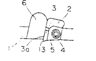
- 축선주위로 회전되는 공구본체의 선단외주부에 절삭날팁이 장착되어 이루어지는 전삭공구에 있어서, 상기한 공구본체(20)에, 그 공구본체(20)를 덮고, 또한, 공구선단측으로 개구하는 커버(34)를 공구축선 주위에 회전가능한 상태로 장착하며, 이 커버(34)에, 커버(34)의 내주면과 공구본체와의 사이에 구획되는 칩수납실(36)과, 커버외부를 연통하는 배출구(37)를 형성하고, 상기한 공구본체(20)의 상기한 칩수납실(36)에 자리잡은 외주면에, 그 공구본체의 회전에 따라서 공구선단측의 공기를 공구기단측으로 흡인하는 회전날개를 형성하며, 상기한 커버(34)에, 상기한 공구본체(20)가 상기한 주축에 장착되는 경우에, 상기한 공작기계의 주축머리(H)와 결합되어 그 커버(34)를 공구본체(20)의 회전에 대하여 구속하고, 또한 상기한 공구본체(20)가 상기한 주축에서 이탈하는 경우에는, 그 공구본체와 결합되어 상기한 커버의 공구본체에 대한 회전을 구속하는 커버구속기구(52)를 배설한 것을 특징으로 하는 전삭공구의 칩 배출기구.
- 제1항에 있어서, 상기한 공구본체(20)의 선단부에, 상기한 절삭날팁의 경사면(21a)과 간극이 생긴 상태로 대향하여 상기한 커버(34)의 공구선단측의 개구부를 좁히는 칩안내부재(41)를 설치한 것을 특징으로 하는 전삭공구의 칩 배출기구.
Applications Claiming Priority (2)
| Application Number | Priority Date | Filing Date | Title |
|---|---|---|---|
| JP2-80159 | 1990-03-28 | ||
| JP2080159A JP2822562B2 (ja) | 1990-03-28 | 1990-03-28 | 転削工具 |
Publications (2)
| Publication Number | Publication Date |
|---|---|
| KR910016420A KR910016420A (ko) | 1991-11-05 |
| KR960010552B1 true KR960010552B1 (ko) | 1996-08-02 |
Family
ID=13710527
Family Applications (1)
| Application Number | Title | Priority Date | Filing Date |
|---|---|---|---|
| KR1019900012033A Expired - Lifetime KR960010552B1 (ko) | 1990-03-28 | 1990-08-06 | 전삭공구의 칩 배출기구 |
Country Status (2)
| Country | Link |
|---|---|
| JP (1) | JP2822562B2 (ko) |
| KR (1) | KR960010552B1 (ko) |
Families Citing this family (4)
| Publication number | Priority date | Publication date | Assignee | Title |
|---|---|---|---|---|
| JP2008002589A (ja) * | 2006-06-23 | 2008-01-10 | Duplo Seiko Corp | 用紙加工装置の動力伝達機構 |
| JP5346611B2 (ja) * | 2009-02-16 | 2013-11-20 | 東洋炭素株式会社 | 面削工具装置 |
| US9937598B2 (en) * | 2010-10-27 | 2018-04-10 | Subaru Corporation | Cover for cutting tool, holder for cutting, and cutting device |
| JP6383162B2 (ja) * | 2014-03-24 | 2018-08-29 | 株式会社三井ハイテック | プレス機のスライド下面の加工方法及びその装置 |
Family Cites Families (3)
| Publication number | Priority date | Publication date | Assignee | Title |
|---|---|---|---|---|
| JPS57170940U (ko) * | 1981-04-17 | 1982-10-27 | ||
| JPS6171313U (ko) * | 1984-10-16 | 1986-05-15 | ||
| JP2535964B2 (ja) * | 1987-10-19 | 1996-09-18 | 三菱マテリアル株式会社 | 転削工具の切り屑排出機構 |
-
1990
- 1990-03-28 JP JP2080159A patent/JP2822562B2/ja not_active Expired - Lifetime
- 1990-08-06 KR KR1019900012033A patent/KR960010552B1/ko not_active Expired - Lifetime
Also Published As
| Publication number | Publication date |
|---|---|
| JPH03281114A (ja) | 1991-12-11 |
| JP2822562B2 (ja) | 1998-11-11 |
| KR910016420A (ko) | 1991-11-05 |
Similar Documents
| Publication | Publication Date | Title |
|---|---|---|
| EP0667209B1 (en) | Rotary cutting tool | |
| KR960010552B1 (ko) | 전삭공구의 칩 배출기구 | |
| US5346341A (en) | Automatic chip removal system for sign engraving machine | |
| JP2535964B2 (ja) | 転削工具の切り屑排出機構 | |
| JP3117533B2 (ja) | 切屑排出装置を備えた正面フライス | |
| KR960010553B1 (ko) | 전삭공구의 칩 배출기구 | |
| JP2547164Y2 (ja) | 切屑排出機構付き転削工具 | |
| JPH07195251A (ja) | エンドミル加工における切屑吸引装置 | |
| KR960003486Y1 (ko) | 전삭공구 | |
| JPH077054Y2 (ja) | 正面フライスの切屑除去装置 | |
| JP2957423B2 (ja) | 転削工具及び転削工具の切屑排出機構 | |
| JPH0751241Y2 (ja) | 切屑吸引機構付き転削工具 | |
| JPH081797Y2 (ja) | 転削工具の切屑排出機構 | |
| KR960010540Y1 (ko) | 칩흡인기구가 부착된 전삭공구 | |
| KR960011083B1 (ko) | 전삭공구의 칩 배출기구 | |
| KR960003487Y1 (ko) | 평면절삭공구 및 칩흡인기구가 부착된 평면절삭공구 | |
| JP2780707B2 (ja) | 転削工具の切り屑排出機構 | |
| JPH0615953U (ja) | 切り屑吸引式転削工具 | |
| JPH078093Y2 (ja) | 転削工具の切屑排出装置 | |
| JPH077053Y2 (ja) | 転削工具の切屑排出装置 | |
| JP2738398B2 (ja) | 切屑排出機構付き転削工具 | |
| JPH088010Y2 (ja) | 転削工具 | |
| KR970000270Y1 (ko) | 전삭공구 및 칩 흡인기구가 설치된 전삭공구 | |
| JPH0744432Y2 (ja) | 切屑吸引機構付き転削工具 | |
| JP2720537B2 (ja) | 転削工具 |
Legal Events
| Date | Code | Title | Description |
|---|---|---|---|
| PA0109 | Patent application |
Patent event code: PA01091R01D Comment text: Patent Application Patent event date: 19900806 |
|
| PG1501 | Laying open of application | ||
| A201 | Request for examination | ||
| PA0201 | Request for examination |
Patent event code: PA02012R01D Patent event date: 19930329 Comment text: Request for Examination of Application Patent event code: PA02011R01I Patent event date: 19900806 Comment text: Patent Application |
|
| E902 | Notification of reason for refusal | ||
| PE0902 | Notice of grounds for rejection |
Comment text: Notification of reason for refusal Patent event date: 19960429 Patent event code: PE09021S01D |
|
| G160 | Decision to publish patent application | ||
| PG1605 | Publication of application before grant of patent |
Comment text: Decision on Publication of Application Patent event code: PG16051S01I Patent event date: 19960711 |
|
| E701 | Decision to grant or registration of patent right | ||
| PE0701 | Decision of registration |
Patent event code: PE07011S01D Comment text: Decision to Grant Registration Patent event date: 19961012 |
|
| GRNT | Written decision to grant | ||
| PR0701 | Registration of establishment |
Comment text: Registration of Establishment Patent event date: 19961030 Patent event code: PR07011E01D |
|
| PR1002 | Payment of registration fee |
Payment date: 19961030 End annual number: 3 Start annual number: 1 |
|
| PR1001 | Payment of annual fee |
Payment date: 19990727 Start annual number: 4 End annual number: 4 |
|
| PR1001 | Payment of annual fee |
Payment date: 20000722 Start annual number: 5 End annual number: 5 |
|
| PR1001 | Payment of annual fee |
Payment date: 20010728 Start annual number: 6 End annual number: 6 |
|
| PR1001 | Payment of annual fee |
Payment date: 20020725 Start annual number: 7 End annual number: 7 |
|
| PR1001 | Payment of annual fee |
Payment date: 20030728 Start annual number: 8 End annual number: 8 |
|
| PR1001 | Payment of annual fee |
Payment date: 20040802 Start annual number: 9 End annual number: 9 |
|
| PR1001 | Payment of annual fee |
Payment date: 20050728 Start annual number: 10 End annual number: 10 |
|
| PR1001 | Payment of annual fee |
Payment date: 20060728 Start annual number: 11 End annual number: 11 |
|
| PR1001 | Payment of annual fee |
Payment date: 20070731 Start annual number: 12 End annual number: 12 |
|
| PR1001 | Payment of annual fee |
Payment date: 20080728 Start annual number: 13 End annual number: 13 |
|
| PR1001 | Payment of annual fee |
Payment date: 20090727 Start annual number: 14 End annual number: 14 |
|
| FPAY | Annual fee payment |
Payment date: 20100728 Year of fee payment: 15 |
|
| PR1001 | Payment of annual fee |
Payment date: 20100728 Start annual number: 15 End annual number: 15 |
|
| EXPY | Expiration of term | ||
| PC1801 | Expiration of term |