KR960010552B1 - Chip ejection mechanism of the turning tool - Google Patents
Chip ejection mechanism of the turning tool Download PDFInfo
- Publication number
- KR960010552B1 KR960010552B1 KR1019900012033A KR900012033A KR960010552B1 KR 960010552 B1 KR960010552 B1 KR 960010552B1 KR 1019900012033 A KR1019900012033 A KR 1019900012033A KR 900012033 A KR900012033 A KR 900012033A KR 960010552 B1 KR960010552 B1 KR 960010552B1
- Authority
- KR
- South Korea
- Prior art keywords
- tool
- cover
- chip
- tip
- tool body
- Prior art date
- Legal status (The legal status is an assumption and is not a legal conclusion. Google has not performed a legal analysis and makes no representation as to the accuracy of the status listed.)
- Expired - Lifetime
Links
Images


Classifications
-
- B—PERFORMING OPERATIONS; TRANSPORTING
- B23—MACHINE TOOLS; METAL-WORKING NOT OTHERWISE PROVIDED FOR
- B23Q—DETAILS, COMPONENTS, OR ACCESSORIES FOR MACHINE TOOLS, e.g. ARRANGEMENTS FOR COPYING OR CONTROLLING; MACHINE TOOLS IN GENERAL CHARACTERISED BY THE CONSTRUCTION OF PARTICULAR DETAILS OR COMPONENTS; COMBINATIONS OR ASSOCIATIONS OF METAL-WORKING MACHINES, NOT DIRECTED TO A PARTICULAR RESULT
- B23Q11/00—Accessories fitted to machine tools for keeping tools or parts of the machine in good working condition or for cooling work; Safety devices specially combined with or arranged in, or specially adapted for use in connection with, machine tools
Landscapes
- Engineering & Computer Science (AREA)
- Mechanical Engineering (AREA)
- Auxiliary Devices For Machine Tools (AREA)
- Milling Processes (AREA)
Abstract
내용 없음.No content.
Description
제1도 내지 제4도는 본 발명의 한 실시예를 표시하는 것으로서, 제1도는 축 방향의 단면도이다.1 to 4 show one embodiment of the invention, in which FIG. 1 is a cross-sectional view in the axial direction.
제2도는 저면도이다.2 is a bottom view.
제3도는 공구본체의 측면도이다.3 is a side view of the tool body.
제4도는 제1도의 I - I선 단면도이다.4 is a cross-sectional view taken along line II of FIG.
제5도는 회전날개 변형예를 표시하는 단면도이다.5 is a cross-sectional view showing a variant of the rotary blades.
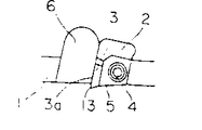
제6도 내지 제8도는 종래의 정면밀링커터(fraise)를 표시하는 것으로서, 제6도는 축방향의 단면도이다.6 to 8 show a conventional front milling cutter, and FIG. 6 is a sectional view in the axial direction.
제7도는 저면도이다.7 is a bottom view.
제8도는 공구본체의 선단외주부의 확대도이다.8 is an enlarged view of the tip outer peripheral part of the tool body.
* 도면의 주요부분에 대한 부호의 설명* Explanation of symbols for main parts of the drawings
20 : 공구본체 21 : 팁(절연팁)20: tool body 21: tip (insulation tip)
21a : 경사면 26 : 절삭날21a: slope 26: cutting edge
34 : 커버 36 : 칩수납실34: cover 36: chip storage room
37 : 배출구 41 : 칩 안내부재37: outlet 41: chip guide member
45 : 칩 안내부재의 단면 50, 60 : 회전날개45: cross section of the
52 : 커버구속 기구 H : 주축 머리52 cover cover mechanism H: spindle head
S : 주축S: spindle
본 발명은, 절삭에 따라서 생성되는 칩을 순차적으로 처리가능한 전삭공구에 관한 것으로, 특히 복합공작기계 등의 자동공구 교환장치를 구비한 공작기계에 사용하기 적합한 전삭공구에 관한 것이다.BACKGROUND OF THE INVENTION 1. Field of the Invention The present invention relates to a grinding tool capable of sequentially processing chips generated in accordance with cutting, and more particularly to a grinding tool suitable for use in a machine tool equipped with an automatic tool changer, such as a composite machine tool.
피절삭재의 평면가공에 사용되는 전삭공구의 한 예로서, 종래로부터, 제6도 내지 제8도에 표시하는 정면밀링 커터가 알려져 있다.As an example of the turning tool used for the planar processing of a to-be-processed material, the front milling cutter shown to FIG. 6 to FIG. 8 is conventionally known.
이들 도면에 표시하는 바와같이, 이 정면밀링커터는, 대략 원통형상을 이루는 커터본체(1)의 선단외주부에, 그 커터본체(1)의 선단면 및 외주면을 향하여 개구하는 오목홈(2)이 원주방향에 등간격으로 복수개 형성되고, 이들 오목홈(2)내에, 드로우어웨이팁(이하, 팁이라고 약칭한다)(3)이 클램프나사(4)로서 고정한 쐐기부재(5)에 의하여 착탈자재하게 장착되는 한쪽에서, 각 팁(3)의 경사면(3a)과 대향하여 접합되는 커터본체(1)의 외주면에, 벽면이 원호형상을 이루는 칩포켓(6)이 형성되고, 다시 커터본체(1)의 중심에 그 커터본체(1)를 축선방향으로 관통하는 중심구멍(7)이 형성되어 이루어지는 것이다.As shown in these figures, this front milling cutter has a
이와같이 구성된 정면밀링커터는, 기체본체의 주축(8)에 키(9)를 개재하여 부착된 아버(10)의 결합축(11)에 중심구멍(7)이 결합된 후, 체결볼트(12)에 의하여 체결되어서 주축(8)과 일체화된다.The front milling cutter is configured such that the
그리고, 이 상태에서, 커터본체(1)가 주축(8)에 의하여 축선주위로 회전됨과 동시에, 축선과 직교하는 방향으로 이송되어서, 팁(3)의 절삭날(13)이 피절삭재를 평면가공하도록 되어 있으며, 이때 생성되는 칩은, 경사면(3a)에서 칩포켓(6)의 벽면으로 유도되어서 말려들어간 다음에 커터본체(1)의 원주방향 바깥쪽으로 배출된다.In this state, the cutter body 1 is rotated around the axis by the
그런데, 상술한 종래의 정면밀링커터는, 생성되는 칩을 단순히 그 주위방향의 바깥쪽으로 유도배출할 따름이므로, 커터본체(1)의 회전에 따라서 칩이 기계주위에 광범하게 비산되고, 이 결과 작업환경이 약화되며, 또 절삭종료후의 칩처리에도 상당한 시간을 요한다는 결점이 있었다.By the way, since the above-mentioned conventional front milling cutter simply draws the produced chip outward of the circumferential direction, the chip scatters widely around the machine as the cutter body 1 rotates, and as a result, There is a drawback that the environment is weakened and a considerable amount of time is required for chip processing after finishing cutting.
또, 절삭을 계속함에 따라서 칩이 피삭재나 기계의 테이블 등에 서서히 퇴적되므로, 이들 칩의 열에 의하여 피절삭재나 기계에 열변형이 발생되어 가공정밀도가 저하된다던지, 또는 절삭날(13)에 칩이 끼어들어가서, 절삭면이 고르지 못한 결점도 있었다.In addition, as the cutting continues, chips are gradually deposited on the workpiece, the table of the machine, or the like, so that heat deformation of the workpiece or the machine occurs due to the heat of the chips, and the precision of the work decreases, or the chips are formed on the
또, 기계주위에 비산된 칩이 미끄럼 이동면 등에 들어가서, 기계자체의 정밀도 저하나, 수명저하를 초래할 우려도 있었다.In addition, chips scattered around the machine may enter a sliding surface or the like, resulting in a decrease in the accuracy of the machine itself or a decrease in life.
이러한 결점은, 특히 장시간의 무인운전이 요구되는 복합공작기계에 있어서 보다 심각한 문제점으로 되어, 그 해결이 절실히 요청되고 있다.This drawback becomes a more serious problem, especially in a complex machine tool requiring long unmanned operation, and the solution is urgently required.
본 발명은, 이와같은 배경하에서 이루어진 것으로, 절삭에 따라서 생성되는 칩을 기계주위에 광범하게 비산시키지 않고, 집중처리하는 것이 가능하고, 또한 자동공구 교환장치를 구비한 공작기계에도 지장없이 사용할 수 있는 전삭공구를 제공하는 것을 목적으로 한다.The present invention has been made under such a background, and it is possible to concentrate the chips generated by cutting without scattering widely around the machine, and can also be used without difficulty in machine tools equipped with an automatic tool changer. An object is to provide a turning tool.
상기한 과제를 해결하기 위하여, 본 발명의 전삭공구는, 공구본체에, 그 공구분체를 피복하며 또한, 공구선단쪽으로 개구한 커버를 공구축선 주위로 회전가능한 상태로 장착하고, 이 커버에, 커버의 내주면과 공구본체와의 사이에 구획하여 형성되는 칩수납실과 커버외부를 연통하는 배출구를 형성하여, 그 공구본체의 회전에 따라서 공구선단측의 공기를 공구기단측으로 흡입하는 회전날개를 형성하고, 상기한 커버에, 상기한 공구본체가 상기한 주축에 장착되는 경우에는, 상기한 공작기계의 주축머리와 결합되어 그 커버를 공구본체의 회전에 대하여 구속하고, 또한, 상기한 공구본체를 상기한 주축에서 떼어낼 경우에는, 그 공구본체와 결합되어, 상기 한 커버의 공구본체에 대한 회전을 구속하는 커버구속기구를 배설한 것이다.In order to solve the above-mentioned problems, the turning tool of the present invention covers the tool powder and covers the tool powder, and mounts a cover open toward the tool tip in a rotatable manner around the tool axis, and covers the cover. A discharge port communicating with the outside of the chip compartment and the cover formed by partitioning between the inner circumferential surface of the tool body and the cover body, and forming a rotary wing that sucks air from the tool tip side to the tool base side according to the rotation of the tool body, When the tool body is mounted on the cover, the tool body is engaged with the head of the machine tool and restrains the cover against rotation of the tool body. In the case of detaching from the main shaft, a cover restraint mechanism is provided which is coupled to the tool body and restrains the rotation of the tool body of the cover.
이 경우, 칩을 한층 정확하게 회수하려면, 공구본체의 선단부에 절삭날팁의 경사면과 간극을 둔 상태로 대향하여, 상기한 커버의 공구선단측의 개구부를 좁히는 칩 안내부재를 설치하는 것이 바람직하다.In this case, in order to recover the chip more accurately, it is preferable to provide a chip guide member for narrowing the opening on the tool tip side of the cover while facing the gap with the inclined surface of the cutting tip at the tip of the tool body.
상기한 구성의 전삭공구에 있어서는, 공구본체의 회전에 따라서 회전날개가 회전되는 것에 의해, 공구선단측의 공기가 기단쪽으로 흡인되므로서, 공구주위의 공기가 커버의 개구부에서 내부로 흡인되고, 이것에 따라서 절삭날팁에서 생성되는 칩이 순차적으로 칩수납실에 흡인된다.In the electrocution tool having the above-described configuration, by rotating the rotor blades in accordance with the rotation of the tool main body, air at the tool tip side is sucked toward the proximal end, so that air around the tool is sucked in through the opening of the cover. As a result, chips generated at the cutting edge tips are sequentially attracted to the chip storage chamber.
이 때문에, 커버의 배출구에서 칩을 집중적으로 회수할 수 있다.For this reason, the chip | tip can be collect | recovered intensively at the discharge port of a cover.
또, 공구본체의 주축으로의 장착시에, 커버가 주축머리쪽과 결합되는 것에 의하여, 공구본체가 회전하여도 커버는 소정위치에 유지된다.In addition, when the tool body is mounted on the main shaft, the cover is engaged with the head of the main shaft so that the cover is held at the predetermined position even when the tool body rotates.
그런 한편, 공구본체를 주축에서 떼어낼 경우에는, 커버와 공구본체가 결합되어 커버의 공구본체에 대한 회전이 구속되므로서, 복합공작기계 등에서 자종공구 교환을 실시하는 경우에, 커버가 회전하여 공구교환동작을 손상시키는 등의 폐해가 발생되지 않고, 공구교환을 실시할 때마다 배출구의 원주방향의 위치가 변화되는 일도 없다.On the other hand, when the tool body is detached from the main shaft, the cover and the tool body are coupled and the rotation of the cover is restrained with respect to the tool body. When the tool is replaced in a multi-task machine or the like, the cover rotates and the tool is rotated. No damage such as impairing the replacement operation occurs, and the position in the circumferential direction of the discharge port does not change every time the tool is changed.
또, 칩 안내부재를 설치하는 것에 의해, 커버의 개구면적이 감소되므로서, 공구 선단부에 발생되는 흡인력이 증대함과 아울러, 절인팁의 경사면을 따라서 생성되는 칩이 칩 안내부재와 경사면과의 간극을 따라서 강제적으로 칩수납실쪽으로 안내된다.In addition, by providing the chip guide member, the opening area of the cover is reduced, so that the suction force generated at the tip of the tool is increased, and the chip generated along the inclined surface of the picking tip has a gap between the chip guide member and the inclined surface. Therefore, it is forcibly guided to the chip storage chamber.
실시예Example
이하, 제1도 내지 제4도를 참조하여, 본 발명의 한 실시예를 설명한다.Hereinafter, an embodiment of the present invention will be described with reference to FIGS. 1 to 4.
이들의 도면에 있어서, 참조부호(20)은 공구본체이다.In these figures,
제1도 내지 제3도에 표시하는 바와같이, 공구본체(20)는 그의 선단외주부에 복수의 팁(절삭날 팁)(21)이 장착되는 한편, 그의 기단측에 아버(22)가 끼워져서 볼트(23)로서 동축적으로 연결되어서 이루어지는 것이다.As shown in Figs. 1 to 3, the
여기에서, 상기한 팁(21)은 초경합금을 정방형의 평판형상으로 성형하여 이루어지는 것으로, 공구본체 외주부의 오목홈(24)에 삽입된 쇄기부재(25)에 의하여 눌려서 공구본체(20)에 착탈자재하게 장착되어 있다.Here, the
그리고, 각팁(21)의 절삭날(26)…은 각각 공구외주 및 선단에서 약간 돌출되어 있다.And cutting
한편, 상기한 아버(22)는, 그 공구본체(20)를 공작기계의 주축머리(H)에 지지된 주축(S)과 연결하기 위한 것으로서, 그의 테이퍼생크(27)가 주축(S)과 결합된 상태에서 플스터드(pull stud)(28)가 주축후단축(제1도에 있어서 윗쪽)으로 이동함에 의하여 주축(S)에 장착된다.On the other hand, the
그리고, 이 아버(22)에는, 키홈(29)이 형성되고, 이들 키홈(29)이 상기한 플스터드(28)의 이동동작에 따라서 주축(S)의 키(30)와 결합하는 것에 의해, 주축(S)이 회전이 공구본체(20)에 전달되도록 되어 있다. 또, 아버(22)에는, 공작기계에 설치된 자동공구 교환장치의 공구교환아암(도면에 표시를 생략)과 결합되는 그립(31)이 형성되어 있다.In this
이 그립(31) 보다는 공구선단측에는, 레디얼베어링(32)이 끼워지고, 그의 내륜쪽은 너트(33)로서 축방향으로 체결되어 있다.The
그리고 레디얼베어링(32)의 의륜측에는 커버(34)가 끼워져 있다.The
이 커버(34)는, 그의 기단측이 상기한 레디얼베어링(32)의 외륜에 체결된 캡(35)과 볼트(35a)로 연결되고, 이것에 의하여 커버(34)는, 그 축방향의 이동이 구속되어서 공구본체(20)에 회전자재하게 지지되어 있다.This
커버(34)의 선단부는, 공구선단을 향하여 개구하는 원통형상으로 형성되고, 그 선단과 팁(21)의 코너부 사이의 거리(ℓ1)는, 공구외주측을 향하는 절삭날(26)의 절입깊이 보다도 어느 정도 크게 설정되어 있다.The tip end of the
또, 커버(34) 선단부의 내경은, 상기한 절삭날(26)의 회전직경보다도 약간 크게 설정되어 있다.The inner diameter of the tip of the
이 커버(34)의 내주면과 상기한 절삭갈(26)사이의 지름방향의 간극량(δ)은, 피절삭재의 재질이나 절삭조건등에 따라서 적당하게 설정되지만, 0.5㎜ 내지 2㎜의 범위내로 설정하는 것이 바람직하고, 보다 정확한 칩처리를 실시하려면 0.5㎜ 내지 1㎜의 범위내로 설정하는 것이 바람직하다.The gap amount δ in the radial direction between the inner circumferential surface of the
간극량(δ)이 0.5㎜미만이면, 커버(34)의 편심 등에 의하여 절삭날(26)이 손상될 우려가 있으며, 또, 간극량(δ)이 2㎜를 초과하면 뒤에 설명하는 칩흡인력이 저하되어, 칩처리에 지장을 초래할 우려가 있기 때문이다.If the gap amount δ is less than 0.5 mm, the
또, 커버(34)의 외주부에는, 그 커버(34)의 내주면과 공구본체(20)의 외주면과의 사이에 구획형성되는 칩수납실(36)과, 커버(34)의 외부를 연통하는 원형의 배출구(37)가 형성되어 있다.The outer circumferential portion of the
그리고, 이 배출구(37)에 중공형상의 배출관(39)이 끼워져 있다.A
또, 커버(34)의 내주면의 상부에는, 칩수납실(36)과 레디얼베어링(30)을 격리시키는 격벽(40)이 형성되어 있다.Moreover, the
제2도 및 제3도에 의하여 상세하게 표시하는 바와같이, 공구본체(20)의 선단의 각 팁경사면(21a)과 대향하는 위치에는, 평판형상의 칩안내부재(41)가 배설되어 있다.As shown in detail in FIG. 2 and FIG. 3, a flat
이들 칩안내부재(41)는, 공구본체(20)의 부착시이트(42)에 설치되어서 볼트(43)로서 고정되고, 그의 표면은 공구본체(20)의 선단면과 대략 면일치하게 되어 있다.These
이들 칩안내부재(41)의 외주측은, 공구본체(20)에 형성된 칩포켓(44)을 거의 폐쇄하는 형상으로 형성되어 있다.The outer circumferential side of these
그리고, 각 칩안내부재(41)의 상기한 경사면(21a)과 대향하는 단면(45)과 경사면(21a)과의 사이에는, 절삭날(26)에서 생성되는 칩을 칩수납실(36)측으로 안내하는 소정이 간극(t)이 설정되어 있다.And between the
이 간극(t)의 크기는, 피절삭재의 재질이나 절삭조건 등에 따라서 적당하게 설정되나, 가급적 0.5㎜ 내지 2㎜의 범위로 설정하는 것이 바람직하다.The size of the gap t is appropriately set according to the material, cutting conditions, and the like of the workpiece, but preferably set in the range of 0.5 mm to 2 mm.
간극량(t)이 0.5㎜미만이면, 칩에 의한 막힘이 발생될 우려가 있으며, 또, 한편, 간극량(t)이 2㎜를 초과하면, 칩흡인력이 저하되어 칩처리능력이 손상될 우려가 있기 때문이다.If the gap amount t is less than 0.5 mm, clogging due to the chip may occur. On the other hand, if the gap amount t exceeds 2 mm, the chip suction force may be lowered and the chip processing capacity may be impaired. Because there is.
그리고, 또 칩안내부재(41)의 이면에는, 상기한 단면(45)에서 칩포켓(44)의 벽면을 향하여 연장된 홈부(46)가 형성되어, 상기한 간극(t)을 통과하는 칩의 막힘을 방지하여, 칩을 지체없이 칩포켓(44)으로 배출시키도록 되어 있다.Further, on the rear surface of the
또, 제1도 및 제3도에 표시하는 바와 같이, 상기한 공구본체(20)의 외주면에는 복수의 회전날개(50)가 형성되어 있다.As shown in Figs. 1 and 3, a plurality of
이들 회전날개(50)는, 공구본체(20)의 외주부를 원주방향으로 소정의 간극으로 깎아 들어가는 것에 의하여 형성되는 것으로, 그 형상은, 공구선단측에서 기단측으로 향함에 따라서 점차 공구회전방향의 후방측으로 경사지도록 설정되어 있다.These
제1도에 표시하는 바와 같이, 상기한 커버(34)의 기단측은 선단부의 축방향으로 팽창되는 타원형상으로 형성되고, 이 타원형상의 돌출부(51)에는 커버구속기구(52)가 설치되어 있다.As shown in Fig. 1, the proximal end of the
이 커버의 구속기구(52)는, 상기한 커버(34)의 회전을 구속하기 위한 것으로서, 상기한 돌축부(51)의 안내구멍(53)에 자유자재로 미끄럼이동하게 삽입된 결합축(54과, 이 결합축(54)을 공구축선방향의 기단측으로 밀어내는 코일스프링(55)과, 결합축(54)에서 공구경방향의 중심측으로 연장된 스톱퍼(56)로서 개략적으로 구성되어 있다.The
여기에서, 상기한 결합축(54)은, 그 키홈(54a)이 상기한 돌출부(51)에 체결된 나사(57) 선단과 결합되어 그 회전이 구속되어 있다.Here, the above-mentioned
또, 결합축(54)의 선단은, 상기한 아버(22)가 주축(S)에 끼워진 상태에 있어서, 공작기계의 주축머리(H)에 부착된 결합블록(58)의 결합구멍(59)에 끼워져서, 커버(34)의 회전을 구속할 수 있도록 되어 있다.Moreover, the distal end of the engaging
또, 제1도 및 제4도에 표시하는 바와같이, 상기한 스톱퍼(56)는, 그 선단이, 아버(22)에 형서된 결합홈(60)에 도달하는 위치까지 연장되고, 상기한 결합축(56)의 축선방향으로의 이동에 따라서 계합홈(60)에서 출몰할 수 있도록 되어 있다.Moreover, as shown in FIG. 1 and FIG. 4, the said
다음에, 이상과 같이 구성된 정면밀링커터의 작용에 대하여 설명한다.Next, the operation of the front milling cutter configured as described above will be described.
상기한 구성의 정면밀링커터는, 공작기계의 자동공구 교환장치의 매거진(도면에 표시를 생략)안에 수납되고, 이 상태에서 자동공구 교환장치의 공구교환아암으로 반송되어서 주축(S)에 장착된다.The front milling cutter of the above-mentioned structure is accommodated in the magazine (not shown in the figure) of the automatic tool changer of a machine tool, is conveyed to the tool change arm of an automatic tool changer, and is attached to the main shaft S in this state. .
이러한 동안에, 결합축(54)은, 코일스프링(55)에 의하여 공구기단쪽으로 밀려나고, 이 때문에, 스톱퍼(56)는 아버(22)의 결합홈(60)과 결합된다.During this time, the
따라서, 매거진 수납상태 및 공구교환중에 있어서는, 커버(34)의 회전이 저지되어, 커버(34)는 아버(22)에 대하여 원주방향 소정위치에 구속된다.Therefore, the rotation of the
이어서, 아버(22)가 주축(S)에 장착되는 것에 의해, 결합축(54)의 선단부는 주축머리(H)에 고정된 결합블록(58)의 결합구멍(59)에 끼워진다.Subsequently, the
이것에 의하여, 결합축(54)은 코일스프링(55)에 저항하여 공구선단축으로 눌려지고, 이 결과 스톱퍼(56)는 아버(22)의 결합홈(60)에서 개방된다.As a result, the
이것에 의하여, 아버(22) 및 커버(34)는 서로 독립하여 회전가능한 상태에 놓여지지만, 커버(34)는 계속적으로 결합축(54)을 개재하여 결합블록(58)과 결합되므로, 그 회전이 구속된다.Thereby, the
아버(22)가 주축(S)에 장착된 후, 공구본체(20)가 주축(S)에 의하여 축선주위로 회전됨과 아울러, 공구선단과 대향하는 피절삭재와 주축(S)과의 사이에 공구축선과 직교하는 방향의 상대운동이 부여되고, 이것에 따라서 팁(21)의 절삭날(26)이 피절삭재를 절삭한다.After the
여기에서, 상기한 절삭시에 있어서는, 공구본체(20)의 회전에 따라서 그 공구본체(20)의 외주에 설치된 회전날개(50)도 일체적으로 회전되고, 이것에 의하여 공구선단축의 공기가 순차적으로 공구기단으로 흡입된다.Here, at the time of said cutting, the
이 때문에, 커버(34) 선단의 개구부분에서는, 공구본체(20)의 주위공기가 칩수납실(36) 안을 향하여 순차적으로 흡인된다.For this reason, the surrounding air of the tool
한편, 상기한 팁(21)의 절삭날(26)에서 경사면(21a)을 따라서 생성되는 칩은, 칩안내부재(41)의 단면(45)과 경사면(21a)과의 사이의 간극(t)을 통고하여 칩포켓(44)에 유도되고, 그 칩포켓(44)에 의하여 말려들어가서 분단된다.On the other hand, the chip generated along the inclined surface 21a at the
그리고, 분단된 칩은, 커버(34)의 선단개구부에서 흡인되는 공기와 함께 칩수납실(36)내로 흡인된다.The divided chip is sucked into the
그리고, 흡인된 칩은, 배출구(37)에서 배출관(39)을 개재하여 커버(34)의 외부에 집중적으로 배출된다.Then, the sucked chip is discharged intensively to the outside of the
가공이 종료되어 주축(S)에서 공구를 빼낼 경우에는, 공구본체(20)는, 공구교환아암과의 결합을 위하여, 주축(S)의 오리엔테이션 기능에 의하여 주축(S)으로의 장착시와 원주방향의 동일위치에 위치결정되고, 이것에 따라서 아버(22)의 결합홈(60)은, 스톱퍼(56)의 선단과 대응하는 위치에 위치결정된다.When machining is completed and the tool is pulled out from the spindle S, the
그리고, 상기한 공구교환아암에 의하여 아버(22)가 주축(S)에서 이탈됨과 동시에, 결합축(54)이 코일스프링(55)에 의하여 공구축선방향의 기단쪽으로 복귀되고, 이 것에 따라서 결합홈(60)과 스톱퍼(56)가 다시 결합된다.The
이것에 의하여, 커버(34)의 회전은 다시 아버(22)에 의하여 구속되게 된다.As a result, the rotation of the
이 때문에, 공구교환시나 공구를 수납하는 매거진을 구동할 때의 커버(34)의 유동이 저지되고, 공구교환을 반복하여도 배출구(37) 및 배출관(39)의 원주방향의 위치는 항상 일정하게 된다.For this reason, the flow of the
따라서, 칩의 배출위치가 항상 일정하게 되므로, 기계측의 배출관(39)이 자리잡은 위치에 칩수납상자 등의 칩처리장치를 실시하는 것에 의하여, 기계측에서 용이하게 칩의 집중처리를 도모할 수 있다.Therefore, since the discharge position of the chip is always constant, a chip processing apparatus such as a chip storage box is provided at the position where the
위에서 설명한 바와 같이, 본 실시예의 정면밀링커터에 의하면, 회전날개(50)의 회전에 따른 흡인력에 의하여, 절삭시에 생성되는 칩이 흡인되어 커버(34)외부의 특정위치에 집중적으로 배출되므로, 그 칩배출위치에서 칩을 집중처리하여, 작업환경의 개선, 칩처리에 요하는 시간의 단축화 등을 도모할 수 있다.As described above, according to the front milling cutter of the present embodiment, due to the suction force due to the rotation of the
다시, 칩흡인력이 공구본체(20)에 형성된 회전날개(50)에 의하여 발생되는 것이므로, 칩을 흡인하기 위하여 흡인기 등의 특별한 기계쪽에 설치할 필요가 없고, 이 때문에 장치가 간단하고, 또한, 가격이 저하된다는 잇점이 있다.In addition, since the chip suction force is generated by the
추가로, 본 실시예의 정면밀링커터에 있어서는, 주축(S)에서 이탈된 상태에서 커버(34)가 아버(22)에 대하여 원주방향의 소정위치에서 구속되고, 또 아버(22)의 주축(S)으로의 장착에 연동하여 커버(34)가 아버(22)와의 결합이 해제되는 구조이므로, 자동공구 교환장치를 구비한 복합공작기계 등의 공작기계에도 하등의 지장없이 사용될 수 있어서, 복합공작기계에 의한 장시간의 무인가공을 실시하는 경우 등과 같이, 생성되는 칩의 양이 많고, 또한, 작업자에 의한 칩처리를 기대할 수 없는 경우에 현저한 효과를 발휘한다.In addition, in the front milling cutter of the present embodiment, the
덧붙이면, 커버구속기구(52)를 설치하지 않는 경우에 있어서, 공구교환을 할 경우나, 또는 공구가 수납된 매거진을 구동하는 경우 등에는 커버(34)가 원주방향으로 유동하여 공작기계나 다른 공구 등에 간섭할 우려가 있고 또, 공구교환을 실시할 때마다 배출구(37)의 주위방향의 위치가 변화하여 칩의 배출위치가 일정하지 않으므로, 칩 배출방향이 공구교환때마다 변화하여 처리가 불가능하게 된다.In addition, the
또한, 본 실시예에서는, 특히 공구본체(20)의 선단에 팁(21)을 정착한 소위 드로우어웨이식의 정면밀링커터에 대하여 설명하였으나, 본 발명의 전삭공구는 이것으로 국한되는 것은 아니고, 팁을 납땜한 정면밀링커터등, 각종의 전삭공구에 적용되는 것이다.In addition, in the present embodiment, the so-called drawaway type front milling cutter, in which the
또, 본 실시예에서는, 특히 회전날개(50)를 공구본체(20)와 일체로 형성하고 있지만, 본 발명은 이것에 국한되는 것은 아니고, 예컨대 제5도에 표시하듯이, 별도로 제작된 회전날개(60)를 공구본체(20)의 외주부에 끼워서 볼트(61)로서 체결하는 구성이라도 좋다.In the present embodiment, in particular, the
또, 회전날개(50)의 형상에 대하여서도, 상기한 실시예에서는 특히, 공구선단측에서 기단측으로 나아감에 따라서 점차 공구회전방향의 후방쪽으로 경사지는 측류식 날개형상으로 형성하고 있으나, 본 발명은 이것에 국한되는 것은 아니고, 예컨대 평면에서 볼 때 소용돌이 형상의 소위 원심날개형상으로 형성하여도 동일한 효과를 발휘할 수 있고, 기타 각종의 변형이 가능하다.In addition, in the embodiment described above, the shape of the
다시, 본 실시예에서는 특히, 공구본체(20)의 선단면에 칩안내부재(41)를 설치하는 것에 의해, 커버(34)의 개구부를 좁히고 있으나, 회전날개(50)에 의하여 충분한 흡인력이 얻어지는 경우에는 생략하여도 상관없다.Again, in this embodiment, in particular, the opening of the
위에서 설명한 바와같이, 본 발명에 의하면, 절삭시에 생성되는 칩을 기계주위에 비산시키지 않고, 순차적으로 흡인하여, 공구주위의 특정한 위치에 집중적으로 배출되므로서, 기계의 배출구의 소정위치에 칩처리장치를 배설함에 의하여, 칩을 집중처리하여 칩처리시간의 단축이나, 작업환경의 대폭적인 개선 등을 도모할 수 있다.As described above, according to the present invention, the chips generated at the time of cutting are sucked sequentially without being scattered around the machine, and are discharged intensively at a specific position around the tool, thereby chip processing at a predetermined position of the discharge port of the machine. By disposing the device, the chip can be centralized to shorten the chip processing time, to drastically improve the working environment, and the like.
게다가, 칩흡인력이 공구본체의 외주부에 설치된 날개에 의하여 발생되는 구성이므로, 칩의 흡인을 위하여 흡인기 등의 특별한 장치를 설치할 필요가 없으므로, 장치가 간단하고 가격도 낮아지는 효과를 발휘한다.In addition, since the chip suction force is generated by the blades provided on the outer circumference of the tool body, it is not necessary to install a special device such as a suction device for the chip suction, thereby providing an effect that the device is simple and the price is lowered.
이에 더하여, 공구가 공작기계의 주축에서 이탈한 상태에 있어서는, 커버가 공구본체에 대하여 원주방향의 소정위치에 구속되고, 또 공구본체를 주측에 장착하는 경우에는, 이것에 연동되어 커버와 공구본체와의 결합이 해제됨과 동시에 커버와 공작기계가 결합하여 커버가 공구본체의 회전에 대하여 소정위치에 유지되므로, 자동공구 교환장치를 구비한 공작기계에도 하등 지장없이 사용할 수 있어서, 장시간 무인가공을 실시하는 경우, 특히, 칩의 생성량이 많고 작업자에 의한 칩처리도 기대할 수 없는 경우에 현저한 효과를 발휘한다.In addition, when the tool is separated from the main axis of the machine tool, the cover is constrained to a predetermined position in the circumferential direction with respect to the tool body, and when the tool body is mounted on the main side, the cover and the tool body are interlocked with this. The combination of the cover and the machine tool is released, and the cover is held at a predetermined position with respect to the rotation of the tool body. Therefore, the machine can be used without difficulty even for a machine tool equipped with an automatic tool changer. In particular, when the amount of chips generated is large and the chip processing by the operator cannot be expected, a significant effect is obtained.
다시, 공구본체의 선단에 칩안내부재를 설치한 경우에는, 커버의 개구면적이 감소되어 공구선단부에 작용하는 흡인력이 증대됨과 동시에, 경사면을 따라서 생성되는 칩이 강제적으로 칩수납실측으로 안내되므로서, 칩을 보다 정확하게 흡인할 수 있는 효과를 발휘한다.In addition, when the chip guide member is provided at the tip of the tool body, the opening area of the cover is reduced to increase the suction force acting on the tool tip, and the chips generated along the inclined surface are forcibly guided to the chip storage chamber side. The effect is that the chip can be sucked more accurately.
Claims (2)
Applications Claiming Priority (2)
| Application Number | Priority Date | Filing Date | Title |
|---|---|---|---|
| JP2-80159 | 1990-03-28 | ||
| JP2080159A JP2822562B2 (en) | 1990-03-28 | 1990-03-28 | Milling tool |
Publications (2)
| Publication Number | Publication Date |
|---|---|
| KR910016420A KR910016420A (en) | 1991-11-05 |
| KR960010552B1 true KR960010552B1 (en) | 1996-08-02 |
Family
ID=13710527
Family Applications (1)
| Application Number | Title | Priority Date | Filing Date |
|---|---|---|---|
| KR1019900012033A Expired - Lifetime KR960010552B1 (en) | 1990-03-28 | 1990-08-06 | Chip ejection mechanism of the turning tool |
Country Status (2)
| Country | Link |
|---|---|
| JP (1) | JP2822562B2 (en) |
| KR (1) | KR960010552B1 (en) |
Families Citing this family (4)
| Publication number | Priority date | Publication date | Assignee | Title |
|---|---|---|---|---|
| JP2008002589A (en) * | 2006-06-23 | 2008-01-10 | Duplo Seiko Corp | Power transmission mechanism for sheet processor |
| JP5346611B2 (en) * | 2009-02-16 | 2013-11-20 | 東洋炭素株式会社 | Face milling tool device |
| US9937598B2 (en) * | 2010-10-27 | 2018-04-10 | Subaru Corporation | Cover for cutting tool, holder for cutting, and cutting device |
| JP6383162B2 (en) * | 2014-03-24 | 2018-08-29 | 株式会社三井ハイテック | Processing method and apparatus for lower surface of slide of press machine |
Family Cites Families (3)
| Publication number | Priority date | Publication date | Assignee | Title |
|---|---|---|---|---|
| JPS57170940U (en) * | 1981-04-17 | 1982-10-27 | ||
| JPS6171313U (en) * | 1984-10-16 | 1986-05-15 | ||
| JP2535964B2 (en) * | 1987-10-19 | 1996-09-18 | 三菱マテリアル株式会社 | Chip removal mechanism for rolling tools |
-
1990
- 1990-03-28 JP JP2080159A patent/JP2822562B2/en not_active Expired - Lifetime
- 1990-08-06 KR KR1019900012033A patent/KR960010552B1/en not_active Expired - Lifetime
Also Published As
| Publication number | Publication date |
|---|---|
| JPH03281114A (en) | 1991-12-11 |
| JP2822562B2 (en) | 1998-11-11 |
| KR910016420A (en) | 1991-11-05 |
Similar Documents
| Publication | Publication Date | Title |
|---|---|---|
| EP0667209B1 (en) | Rotary cutting tool | |
| KR960010552B1 (en) | Chip ejection mechanism of the turning tool | |
| US5346341A (en) | Automatic chip removal system for sign engraving machine | |
| JP2535964B2 (en) | Chip removal mechanism for rolling tools | |
| JP3117533B2 (en) | Face mill with chip evacuation device | |
| KR960010553B1 (en) | Chip ejection mechanism of the turning tool | |
| JP2547164Y2 (en) | Milling tool with chip discharge mechanism | |
| JPH07195251A (en) | Chip suction device in end mill processing | |
| KR960003486Y1 (en) | Face milling cutter | |
| JPH077054Y2 (en) | Face milling chip remover | |
| JP2957423B2 (en) | Milling tool and chip discharge mechanism of milling tool | |
| JPH0751241Y2 (en) | Rolling tool with chip suction mechanism | |
| JPH081797Y2 (en) | Chip discharging mechanism for rolling tools | |
| KR960010540Y1 (en) | A cutting machine with chip removal device | |
| KR960011083B1 (en) | Rotary cutting tool having a chip suction device | |
| KR960003487Y1 (en) | Face milling cutter having means of sucking chip | |
| JP2780707B2 (en) | Chip discharge mechanism for milling tools | |
| JPH0615953U (en) | Chip suction type cutting tool | |
| JPH078093Y2 (en) | Chip discharging device for rolling tools | |
| JPH077053Y2 (en) | Chip discharging device for rolling tools | |
| JP2738398B2 (en) | Milling tool with chip discharge mechanism | |
| JPH088010Y2 (en) | Rolling tool | |
| KR970000270Y1 (en) | Turning tools with chipping tools and chip suction | |
| JPH0744432Y2 (en) | Rolling tool with chip suction mechanism | |
| JP2720537B2 (en) | Milling tool |
Legal Events
| Date | Code | Title | Description |
|---|---|---|---|
| PA0109 | Patent application |
Patent event code: PA01091R01D Comment text: Patent Application Patent event date: 19900806 |
|
| PG1501 | Laying open of application | ||
| A201 | Request for examination | ||
| PA0201 | Request for examination |
Patent event code: PA02012R01D Patent event date: 19930329 Comment text: Request for Examination of Application Patent event code: PA02011R01I Patent event date: 19900806 Comment text: Patent Application |
|
| E902 | Notification of reason for refusal | ||
| PE0902 | Notice of grounds for rejection |
Comment text: Notification of reason for refusal Patent event date: 19960429 Patent event code: PE09021S01D |
|
| G160 | Decision to publish patent application | ||
| PG1605 | Publication of application before grant of patent |
Comment text: Decision on Publication of Application Patent event code: PG16051S01I Patent event date: 19960711 |
|
| E701 | Decision to grant or registration of patent right | ||
| PE0701 | Decision of registration |
Patent event code: PE07011S01D Comment text: Decision to Grant Registration Patent event date: 19961012 |
|
| GRNT | Written decision to grant | ||
| PR0701 | Registration of establishment |
Comment text: Registration of Establishment Patent event date: 19961030 Patent event code: PR07011E01D |
|
| PR1002 | Payment of registration fee |
Payment date: 19961030 End annual number: 3 Start annual number: 1 |
|
| PR1001 | Payment of annual fee |
Payment date: 19990727 Start annual number: 4 End annual number: 4 |
|
| PR1001 | Payment of annual fee |
Payment date: 20000722 Start annual number: 5 End annual number: 5 |
|
| PR1001 | Payment of annual fee |
Payment date: 20010728 Start annual number: 6 End annual number: 6 |
|
| PR1001 | Payment of annual fee |
Payment date: 20020725 Start annual number: 7 End annual number: 7 |
|
| PR1001 | Payment of annual fee |
Payment date: 20030728 Start annual number: 8 End annual number: 8 |
|
| PR1001 | Payment of annual fee |
Payment date: 20040802 Start annual number: 9 End annual number: 9 |
|
| PR1001 | Payment of annual fee |
Payment date: 20050728 Start annual number: 10 End annual number: 10 |
|
| PR1001 | Payment of annual fee |
Payment date: 20060728 Start annual number: 11 End annual number: 11 |
|
| PR1001 | Payment of annual fee |
Payment date: 20070731 Start annual number: 12 End annual number: 12 |
|
| PR1001 | Payment of annual fee |
Payment date: 20080728 Start annual number: 13 End annual number: 13 |
|
| PR1001 | Payment of annual fee |
Payment date: 20090727 Start annual number: 14 End annual number: 14 |
|
| FPAY | Annual fee payment |
Payment date: 20100728 Year of fee payment: 15 |
|
| PR1001 | Payment of annual fee |
Payment date: 20100728 Start annual number: 15 End annual number: 15 |
|
| EXPY | Expiration of term | ||
| PC1801 | Expiration of term |