KR890004600B1 - Apparatus for cleaning grits - Google Patents
Apparatus for cleaning grits Download PDFInfo
- Publication number
- KR890004600B1 KR890004600B1 KR1019850001882A KR850001882A KR890004600B1 KR 890004600 B1 KR890004600 B1 KR 890004600B1 KR 1019850001882 A KR1019850001882 A KR 1019850001882A KR 850001882 A KR850001882 A KR 850001882A KR 890004600 B1 KR890004600 B1 KR 890004600B1
- Authority
- KR
- South Korea
- Prior art keywords
- base
- stand
- dust box
- vibration
- screen
- Prior art date
Links
Images


Classifications
-
- B—PERFORMING OPERATIONS; TRANSPORTING
- B07—SEPARATING SOLIDS FROM SOLIDS; SORTING
- B07B—SEPARATING SOLIDS FROM SOLIDS BY SIEVING, SCREENING, SIFTING OR BY USING GAS CURRENTS; SEPARATING BY OTHER DRY METHODS APPLICABLE TO BULK MATERIAL, e.g. LOOSE ARTICLES FIT TO BE HANDLED LIKE BULK MATERIAL
- B07B9/00—Combinations of apparatus for screening or sifting or for separating solids from solids using gas currents; General arrangement of plant, e.g. flow sheets
-
- B—PERFORMING OPERATIONS; TRANSPORTING
- B07—SEPARATING SOLIDS FROM SOLIDS; SORTING
- B07B—SEPARATING SOLIDS FROM SOLIDS BY SIEVING, SCREENING, SIFTING OR BY USING GAS CURRENTS; SEPARATING BY OTHER DRY METHODS APPLICABLE TO BULK MATERIAL, e.g. LOOSE ARTICLES FIT TO BE HANDLED LIKE BULK MATERIAL
- B07B1/00—Sieving, screening, sifting, or sorting solid materials using networks, gratings, grids, or the like
- B07B1/46—Constructional details of screens in general; Cleaning or heating of screens
-
- B—PERFORMING OPERATIONS; TRANSPORTING
- B07—SEPARATING SOLIDS FROM SOLIDS; SORTING
- B07B—SEPARATING SOLIDS FROM SOLIDS BY SIEVING, SCREENING, SIFTING OR BY USING GAS CURRENTS; SEPARATING BY OTHER DRY METHODS APPLICABLE TO BULK MATERIAL, e.g. LOOSE ARTICLES FIT TO BE HANDLED LIKE BULK MATERIAL
- B07B4/00—Separating solids from solids by subjecting their mixture to gas currents
- B07B4/08—Separating solids from solids by subjecting their mixture to gas currents while the mixtures are supported by sieves, screens, or like mechanical elements
-
- B—PERFORMING OPERATIONS; TRANSPORTING
- B07—SEPARATING SOLIDS FROM SOLIDS; SORTING
- B07B—SEPARATING SOLIDS FROM SOLIDS BY SIEVING, SCREENING, SIFTING OR BY USING GAS CURRENTS; SEPARATING BY OTHER DRY METHODS APPLICABLE TO BULK MATERIAL, e.g. LOOSE ARTICLES FIT TO BE HANDLED LIKE BULK MATERIAL
- B07B2201/00—Details applicable to machines for screening using sieves or gratings
- B07B2201/04—Multiple deck screening devices comprising one or more superimposed screens
Abstract
Description
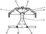
제1도는 본 발명에 따른 장치의 정면도.1 is a front view of the device according to the invention.
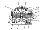
제2도는 제1도의 II-II선 단면도.2 is a cross-sectional view taken along the line II-II of FIG.
제3도는 스탠드와 스탠드 상부를 갖는 본 발명에 따른 개략 측면도.3 is a schematic side view according to the invention with a stand and a stand top;
제4도는 제3도의 구조에 진동장치를 설치한 것을 보인 측면도.4 is a side view showing that the vibration device is installed in the structure of FIG.
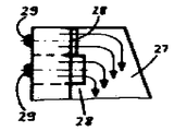
제5도는 본 발명에 따른 장치에서 상부의 공기분배실을 보인 개략 측단면도.5 is a schematic side cross-sectional view showing an upper air distribution chamber in the apparatus according to the present invention.
제6도는 제5도의 VI-VI선 단면도.6 is a sectional view taken along the line VI-VI of FIG.
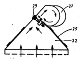
제7도는 제5도에서 보인 구조에 대한 다른 실시형태를 보인 단면도.FIG. 7 is a cross-sectional view of another embodiment of the structure shown in FIG.
제8도는 제7도에서 보인 구조의 부분 평면도.8 is a partial plan view of the structure shown in FIG.
제9도는 가요성 고무연결구로 더스트복스를 지지한 상태를 보인 개략도.9 is a schematic view showing a state in which the dust box is supported by a flexible rubber connector.
제10도는 스프링상에 더스트복스를 지지하고 레바장치상에 진동콘베이어 슈트를 지지한 상태를 보인 개략도.10 is a schematic view showing a state in which a dust box is supported on a spring and a vibration conveyor chute is supported on a lever device.
제11도는 더스트복스로부터 콘베이어슈트로 전달되는 진동전달상태를 설명한 모식도.Figure 11 is a schematic diagram illustrating a vibration transmission state transmitted from the dust box to the conveyor chute.
* 도면의 주요부분에 대한 부호의 설명* Explanation of symbols for main parts of the drawings
1 : 공급구 2 : 배출구1: supply port 2: discharge port
3 : 스크린층 4, 5 : 수집수단3:
6, 7 : 배출구 8 : 더스트복수6, 7: discharge port 8: dust recovery
9 : 스탠드 10 : 스탠드 기부9: stand 10: base donation
12 : 단부지지체 14 : 경사진여진기12: end support 14: inclined exciter
19 : 고무지지체 20 : 레바19: rubber support 20: lever
21 : 수직지지체 22 : 상측 공기분배실21: vertical support 22: upper air distribution chamber
24 : 공기순환실 27 : 흡인수집통로24: air circulation chamber 27: suction collection passage
28 : 조절플랩 30, 31 : 탄성부재28: control flap 30, 31: elastic member
33 : 요입부 34 : 슈트33: recessed part 34: suit
본 발명은 그릿츠(GIRTS) 즉 거칠게 분쇄한 곡물의 분쇄물을 정선하는 장치에 관한 것으로, 특히 양측단부에 위치하여 적어도 하나의 경사진여진기에 의하여 진동 가능한 다수 중첩된 스크린층, 제품의 공급을 위한 공급부, 스크린을 통과하지 못한 것을 배출하기 위한 배출구와, 스크린을 통과하는 것을 조절하고 스크린층을 통하여 흡인수집통로내의 공기분배실로 순환하는 공기순환을 조절하기 위한 플랩을 갖는 수집수단으로 구성되는 그릿츠 정선장치에 관한 것이다.BACKGROUND OF THE INVENTION 1. Field of the Invention The present invention relates to a device for selecting grits (GIRTS), that is, crushed grains of roughly crushed grains. A collecting means having a supply for supplying, an outlet for discharging that has not passed through the screen, and a flap for regulating passing through the screen and adjusting the air circulation circulating through the screen layer into the air distribution chamber in the suction collection passage. It relates to a Ritz selection device.
그릿츠를 정선하기 위한 상기 장치는 거의 제분기에만 사용되는 특수기계를 구성한다. 이들은 일차 분쇄된 초벌 그릿츠로부터 불순물과 곡물 그릿츠를 선별할 수 있도록 한다. 주요기능은 최대입자의 그릿츠류와, 미세하게 갈린 완전한 그릿츠, 혼합제품, 기벼운제품, 특별한 제품(그대로 요리할 수 있는 그릿츠 등), 종자등으로 구성된 그릿츠류를 선별하는 것이며, 미세한 그릿츠의 최대 수율이 기대된다.The apparatus for selecting grit constitutes a special machine used almost exclusively for mills. They make it possible to sort out impurities and grain grits from the primary milled primary grits. The main function is to select grit, which is composed of the largest particles of grit, finely ground complete grit, mixed product, light product, special product (such as cookable grit), seeds, etc. Maximum yield of fine grit is expected.
제품의 공급에 있어 공급량의 변화가 작업특성에 부정적인 영향을 주어서는 않된다. 작업중에 장치의 설정된 특성이 무단히 변화되어서는 않된다.Changes in supply in the supply of the product shall not adversely affect the working characteristics. The set characteristics of the device must not be changed without permission during operation.
산업적인 기계분야의 기본원리에 따라서 다수의 상이한 시스템을 통하여 필요한 구성부품을 얻을 수 있다는 것을 생각할 수 있다. 중요한 기준은 분쇄분(分碎粉)의 무게와 기류내에서 분쇄분의 하강속도 그리고 분쇄분의 크기이다.It is conceivable that the necessary components can be obtained through a number of different systems according to the basic principles of the industrial machinery sector. Important criteria are the weight of the powder, the rate of descent of the powder in the air stream and the size of the powder.
다른 산업적인 기계분야에서도 그와같은 것들은 필요한 것이다. 예를들어 진동기류를 갖는 유동상(流動床), 원심체(centrifugal sifters), 분산장치, 공기분류기와 같은 장치를 위하여서도 이용된다. 그러나 이러한 장치는 그릿츠의 정선장치를 개선하는데에는 이용될 수 없다. 요구된 그릿츠를 얻는데에 관련된 특별한 요구는 18세기초 이래로 알려진 공지의 그릿츠 정선장치에 명백히 부합될 수 있어야 한다. 자전거와 같이 오래전에 공지된 기술은 중요한 새로운 아이디어를 찾아내거나 이를 실시할 수 있는 것을 전환한다는 것은 극히 어렵다.In other industrial machines, such things are necessary. It is also used, for example, for devices such as fluidized beds with vibrating air, centrifugal sifters, dispersers, air classifiers. However, these devices cannot be used to improve Grit's selection. The special requirements relating to obtaining the required grit must be clearly comparable to the known grit selector known since the beginning of the 18th century. It is extremely difficult for long known techniques, such as bicycles, to find important new ideas or to switch from being able to implement them.
그동안 공지의 그릿츠 정선장치가 구조적인면에서나 기능적인면에서 개발되어 왔으며 어떠한 구조적인 조건이 요구되었으나 이 분야에 숙련된자라 할지라도 현저한 개선, 특히 전체적인 구성에 관련된 개선이 더 이상 기대될 수 없었다.In the meantime, the well-known Grit's selection device has been developed in terms of structural and functional aspects, and any structural conditions are required, but even those skilled in the art can not expect any significant improvement, particularly related to the overall configuration.
본 발명은 이러한 형태의 공지된 장치에 비하여 생산성이 개선되고, 선별이 용이하며, 동력이 적게 소요되고, 제작에 있어서 최종제품의 품질과 수율을 낮추지 아니하고 저렴하게 제작될 수 있는 그릿츠 정선장치를 개발하는데 있다.The present invention provides a grit selection apparatus which can be manufactured inexpensively without lowering the quality and yield of the final product in production, improving productivity, making it easier to sort, and requiring less power, compared to the known apparatus of this type. To develop.
본 발명은 이러한 점을 효과적으로 개선한 것으로 본 정선장치는 스탠드 상부를 갖는 스탠드기부와, 상기 상부 및 기부를 연결하는 수직중간 지지체로서 구성되고, 스크린층이 더스트복수(dust box)로서 구성되며 스탠드기부의 부근에서 진동 가능하게 지지되고, 스탠드 상부는 상측 공기분배실로 구성된다. 이러한 구조는 첫째로 보조기능이 주요기능을 위한 자유공간부를 제공하기 위해 방해받지 않는 부위에 설치된다. 그러므로 본 발명의 장치는 외부가 간단하게 설치될 수 있다. 초기시험에서 이러한 장치는 전체적으로 다른 결점없이 효과적으로 나타났다. 아울러 본 발명은 이후 상세히 언급되는 바와같이 구성되는 본 장치에서 다수의 예기치 않은 개선점이 나타났다.The present invention effectively improves this point, and the selection apparatus includes a stand base having a stand upper portion, a vertical intermediate support connecting the upper portion and the base, and a screen layer configured as a dust box and a stand base portion. Vibration is supported in the vicinity of the stand, the upper part of the stand is composed of the upper air distribution chamber. This structure is first installed in an unobstructed area where the auxiliary function provides a free space for the main function. Therefore, the apparatus of the present invention can be installed simply outside. In early trials, these devices proved effective without overall other drawbacks. In addition, the present invention has shown a number of unexpected improvements in the device which are constructed as described in detail below.
복식기계형태로 구성된 본 발명에 따른 그릿츠 정선장치의 경우에 있어서, 스탠드에는 양측단부에 중간지지체를 설치하는 것이 좋다. 더스트복스는 예를들어 스탠드기부구조물상의 스프링장치에 의하여 진동가능하게 지지될 수 있다. 장치의 주요부로서 이 더스트복스는 스탠드기부의 부근에 지지되는 것이 좋으며 그 상측 공간부는 상측 공기분배실의 최적한 구성을 위하여 이용될 수 있다. 본 발명은 제품의 정선과정을 위한 공기의 최적한 분배를 허용한다. 진동장치를 저면부, 좋기로는 스탠드기부에 지지하므로서 진동력이 직접 유도될 수 있다. 스탠드는 그 주요기능으로서 여러 구성부품을 설치하도록 설계될 수 있다. 이들의 실제 작업영역에 그릿츠의 정선과 필요한 기계적인 힘이 집중되므로 작업특성이 유지될 수있고 생산성이 증가될 수 있을 뿐만 아니라 전체 장치의 수명이 연장될 수 있다. 진동이 공기순환부재에는 전달되지 않으므로 공기순환이 이루어지거나 플랩이 이러한 공기순환을 위하여 위치사 설정되었을때에 더 이상의 불필요한 조절이 필요없게 된다.In the case of the grit selecting apparatus according to the present invention configured in the form of a double machine, it is preferable that intermediate stands are provided at both ends of the stand. The dust box may be vibratedly supported by, for example, a spring device on the stand base structure. As the main part of the device, this dust box is preferably supported in the vicinity of the stand base and its upper space can be used for the optimum configuration of the upper air distribution chamber. The present invention allows for optimal distribution of air for the selection process of the product. The vibration force can be directly induced by supporting the vibrating device on the bottom, preferably the stand base. The stand can be designed to install several components as its main function. The grit selection and the necessary mechanical forces are concentrated in their actual working area, which not only maintains the working characteristics, increases productivity, but also prolongs the life of the whole device. Since vibration is not transmitted to the air circulation member, no unnecessary adjustment is necessary when the air circulation is made or when the flap is positioned for this air circulation.
탄성부재는 스탠드와 더스트복스 사이에 배치되어 스탠드와 스탠드 상부가 진동하는 구성부품에 대하여 효과적으로 평형을 이루므로서 실제 장치에 있어서 진동에 의한 장치의 반작용이 줄어들 수 있다. 다른 구체화된 실시형태에 따라서, 탄성부재가 스탠드기부와 스탠드의 중간지지체 사이에 배치될 수 있으며 탄성부재가 스탠드의 중간 지지체와 스탠드 상부 사이에 배치될 수도 있으며 또는 중간 지지체가 그 자체가 탄성부재로서 구성되어 장치의 안정된 작동이 이루어질 수 있도록 할수도 있다.The elastic member is disposed between the stand and the dust box to effectively balance the stand and the top of the stand vibrating components, thereby reducing the reaction of the device due to vibration in the actual device. According to another embodiment, the elastic member may be disposed between the stand base and the intermediate support of the stand and the elastic member may be disposed between the intermediate support of the stand and the top of the stand, or the intermediate support itself is an elastic member. It can also be configured to ensure stable operation of the device.
본 발명에 따라 구체화된 다른 실시형태에 따라서, 중간지지체의 상부는 더스트복스의 상측으로 돌출되어 있고 저면에서는 서로 대칭되게 연결하여 양단부에서는 스탠드기부측으로 연장되고, 두 스탠드기부 사이의 공간부에는 고정된 부재들이 없다. 따라서, 전체 장치의 상부와 측부에는 그 내부와 함께 공기순환을 위한 공간이 형성된다.According to another embodiment embodied according to the invention, the upper part of the intermediate support protrudes upwards of the dust box and connects symmetrically with each other at the bottom to extend to the stand base at both ends, and is fixed to the space between the two stand bases. There are no members. Thus, a space for air circulation is formed at the top and the side of the whole apparatus together with the inside thereof.
더스트복스의 하측에는 저면부에 진동가능하게 지지되고 기부와 더스트복스 사이에 거의 수 센티메타의 흡기간극이 형성된 기부에 의하여 흡기를 위한 하측 공기분배실이 형성되어 공기순환과 최종제품의 분리에 매우 큰 유리한 영향을 줄 수 있다.The lower side of the dust box is vibratingly supported on the bottom part, and a lower air distribution chamber for intake is formed by the base having an absorption period of about several centimeters between the base and the dust box, which is very useful for separating the air circulation and the final product. It can have a big beneficial effect.
지금까지는 흡인방법으로 작동하는 장치의 경우에 있어서는 유동상하측에 있는 흡기 영역으로 흡기되는 순환공기가 공기분배에 현저한 영향을 주지 않는 것이라 하여 특별히 문제될 만한 국소적인 문제점이 없는 것으로 가정되었다. 그러나 본 발명은 공지의 구성에 있어서 하측 공기분배실이 동시에 최종제품의 분배 목적으로도 사용되었으므로 문제의 명확한 근원은 하측 공기분배실에서의 효과가 무시되어 왔음을 인식하게 되었다. 이는 어느 경우든지 분쇄분이 낙하하여 스크린을 통과하는 것으로 믿고 있어 본 발명 이전에는 이점에 대하여 별다른 주의를 주지 않았기 때문으로 생각된다. 본 발명에 따른 해결안은 명확히 구분된 하측 공기분배실을 제공하고 분쇄분의 공급이 이 하측 공기분배실의 하측에서 이루어질 수 있는 반면에 기부에 의하여 분리된다. 일반적로 2-4종류위 분쇄분이 스크린을 통과한후 얻어지며, 입자크기는 길이방향으로 차이가 난다. 본 발명의 다른 유리한 실시형태에 따라서, 각 종류의 분쇄분으로 가장 정확히 분리하기 위하여 기부는 그 중앙의 하측부에 다수의 제품 안내 플랩을 갖는 내향 경사진 콘베이어 슈트로서 구성된다.Until now, it has been assumed that there is no local problem that would be particularly problematic in the case of the device operated by the suction method, since the circulating air sucked into the intake area above and below the fluid does not significantly affect the air distribution. However, the present invention, since the lower air distribution chamber in the known configuration was also used for the purpose of dispensing the final product at the same time, the obvious source of the problem has been recognized that the effect in the lower air distribution chamber has been ignored. It is believed that this is because in any case it is believed that the pulverized powder falls and passes through the screen, so that little attention has been given to the advantages before the present invention. The solution according to the invention provides a clearly distinguished lower air distribution chamber and the grinding of the powder can be made at the lower side of the lower air distribution chamber while separated by the base. Generally, 2-4 kinds of pulverized powder is obtained after passing through the screen, and the particle size varies in the longitudinal direction. According to another advantageous embodiment of the present invention, the base is configured as an inwardly inclined conveyor chute having a plurality of product guide flaps at its lower center in order to most accurately separate each kind of ground powder.
만약 더블 콘베이어 슈트로서 구성된 두 수집장치가 기부의 하측에 배설되고 각각 길이 방향으로 두개의 상이한 배출구를 갖는 경우 요구된 크기에 따라 분쇄분을 분리할 수 있는 특별한 잇점을 갖는바, 저면부는 제품안내플랩의 수에 해당하는 각각의 반원통형 요입부를 가지며, 이 요입부의 하측 개방부는 요구한 바에 따라서 제품 안내 플랩에 의하여 양측의 수집장치측으로 개방될 수 있다. 각각의 경우 회동점에서 경사가능한 슈트의 형태로 설치된 제품안내플랩은 슈트와 기부 사이의 배출구 단면이 흡기 간극의 단면보다 작게 구성되는 것이 좋다. 기류는 저항이 가장 적은 통로를 찾아 흐르게 되므로 이러한 기류는 제품 배출 영역에 기류를 방해할 아무것도 없게되어 본 발명의 해결안으로서 확실하게 보장될 수 있다. 이미 언급된 바와같이, 더스트복스와 같은 방향으로 진동하는 더블 콘베이어 슈트를 스탠드기부상에 직접 배설하여 지지되게 하는 것이 가능하므로 더스트복스의 진동과는 다른 진동이 선택될 수 있다.If the two collectors, configured as double conveyor chutes, are arranged on the underside of the base and each has two different outlets in the longitudinal direction, it has the special advantage of separating the pulverized powder according to the required size. Each semi-cylindrical concave portion corresponds to the number of and the lower opening of the concave portion can be opened to the collecting device on both sides by a product guide flap as required. In each case, the product guide flap installed in the form of a chute tiltable at the pivot point is preferably configured such that the outlet cross section between the chute and the base is smaller than the cross section of the intake gap. Since the airflow flows in the path of least resistance, such airflow can be reliably ensured as a solution of the present invention, since there is nothing in the product discharge area to obstruct the airflow. As already mentioned, a vibration other than the vibration of the dust box can be selected because it is possible to directly support the double conveyor chute vibrating in the same direction as the dust box on the stand base.
본 발명의 다른 유리한 개선점은 기류방향의 관점에서 볼때 공기분배실의 후측에 조절플랩을 구성하는 것이며 또 다른 유리한 개선점은 스크린층의 상부의 공기분배실은 다수의 격벽형 공기순환실을 갖는 원주 경사 형태로 되어 있고 최상측의 스크린층에 근접 연장되게 하는 것이며, 조절플랩이 공기순환실의 경사부 상측단과 흡인통로 사이의 전이부분에 배치되게 한다. 전이부분은 공기순환실의 경사부 상측단과 흡인수집통로 사이에 수평하게 연장되는 것이 좋다.Another advantageous improvement of the present invention is the configuration of a flap on the rear side of the air distribution chamber in terms of the airflow direction. Another advantageous improvement is that the air distribution chamber at the top of the screen layer has a circumferentially inclined shape having a plurality of partition-type air circulation chambers. And extending close to the top screen layer, and the adjusting flap is disposed at the transition portion between the upper end of the inclined portion of the air circulation chamber and the suction passage. The transition portion preferably extends horizontally between the upper end of the inclined portion of the air circulation chamber and the suction collecting passage.
본 발명에 따라서, 더스트복스와 기부는 적당한 진동장치로서 구성되고 두 단부가 스탠드기부상에서 저면부가 진동되도록 지지되어 있다. 또한 더스트복스와 더블 콘베이어 슈트가 공통의 경사진여진기에 의하여 진동되는 경우 더스트복스가 경사진여진기에 고정되어 그 진동방향이 조절되도록 한다. 진동크기를 증가시키기 위하여 더블 콘베이어 슈트는 진동장치에 연결된 레바 조인트에 의하여 구동되는 것이 유리한바, 단부지지체에 의하여 작동하는 레바와 지지체에 따라 더스트복스로부터 수집수단이 진동된다. 단부지지체와 수집수단지지체의 레바의 연결점은 진동범위를 조절하기 위하여 위치가 변동될 수 있다.According to the invention, the dust box and the base are configured as a suitable vibrating device and the two ends are supported such that the bottom part is vibrated on the stand base. In addition, when the dust box and the double conveyor chute are vibrated by a common inclined exciter, the dust box is fixed to the inclined exciter so that the vibration direction thereof is adjusted. In order to increase the vibration size, the double conveyor chute is advantageously driven by a lever joint connected to the vibrator, whereby the collecting means is vibrated from the dust box according to the lever and the support operated by the end support. The connection point of the lever of the end support and the collecting means support may be varied in position to adjust the vibration range.
본 발명에 따라서, 더스트복스는 스프링장치에 의하여 지지되어 진동으로부터 영향받지 않는 별도의 독립된 진동구조체가 주어질 수 있다. 이 스프링장치는 중공형의 고무제스프링, 강철스프링 또는 가요성의 고무연결구로 구성되는 것이 좋다. 이는 진동여진기를 더스트복스에 고정할 수 있도록 하는 반면에 그 진동방향을 조절할 수 있도록 하며 진동장치의 중심(重心)에 대한 진동의 힘작용 방향의 기능으로서 더스트복스의 진동에 있어 진동개시와 종료를 어느방향에서나 조절할 수 있고 필요한 경우 그 세기를 조절할 수 있다. 더스트복스로부터 지지된 레바장치를 통하여 조절가능하게 진동되는 것이 가능한 수집수단은 비록 동일한 경사진여진기에 의하여 진동이 일어나나 더스트복스의 진동에 관계없이 그 진폭이 선택될 수 있다.According to the invention, the dustbox can be given a separate independent vibration structure which is supported by the spring device and is not affected by vibration. The spring device is preferably composed of hollow rubber springs, steel springs or flexible rubber connectors. This allows the vibration excitator to be fixed to the dust box, while the vibration direction can be adjusted, and the vibration start and end of the vibration box as a function of the direction of the force acting on the vibration of the vibration device. You can adjust it in either direction and adjust its intensity if necessary. The collecting means capable of being adjustablely vibrated through the lever device supported from the dustbox, although the vibration is caused by the same inclined exciter, its amplitude can be selected irrespective of the vibration of the dustbox.
본 발명을 첨부도면에 의거하여 보다 상세히 설명하면 다음과 같다.Referring to the present invention in more detail based on the accompanying drawings as follows.
먼저, 제1도와 제2도에서는 제2도에 표시된 바와같은 복식형 그릿츠 선별장치를 표시한 것이다. 이는 중앙의 스탠드 구조물을 중심으로 좌우측부에 독립적으로 배설되어 있다. 도면의 상부좌측에는 공급구(12)가 있고 하부우측에는 스크린을 통과하지 못한 분쇄물의 배출구(2)가 표시되어 있다. 3개의 스크린이 중첩된 것을 부호(3)으로 표시하며 스크린층(3)의 하측에는 내측수집수단(4)과 외측수집수단(5)(제2도)이 도시되어 있다. 이들은 스크린을 통과한 그릿츠를 수집하며, 각각의 수집수단(4)(5)은 두개의 배출구(6)(7)를 갖는다. 스크린층(3)은 각기 조합되어 더스트복스(8)(제2도)를 구성하며, 실시형태에 따라서, 각 더스트복스(8)는 스크린을 통과하지 못한 것을 배출하기 위한 두개의 배출구(2)와 스크린을 통과한 것을 배출하기 위한 4개의 배출구(6)(7)를 갖는다. 또한 더스트복스(8)는 스탠드(9)의 스탠드기부(10)상에 착설된 진동부재, 즉 중공형의 고무 스프링(13)을 통하여 단부지지체(12)(제1도)에 의하여 진동기능하게 지지된다. 경사진여진기(14)가 단부지지체(12)에 착설되고 그 진동방향(제1도의 화살표15)은 관상 횡연결구(16)상에서 경사진여진기(14)를 여자시키므로서 조절될 수있다. 아울러, 공지된 바와같이 이러한 여자의 힘의 강도는 경사진 중량체(17)의 설정으로 조절 될 수있다, 두 경사진여진기(14)는 횡연결구(16)에 고정되고 전기적으로 연결되어 있으며 이들 경사진여진기(14)는 상호 반대방향으로 회전된다. 이는 이들의 측방향 비평형 운동이 상쇄되어 순수한 직선상의 길이방향 진동만이 화살표(15) 방향으로 유도되도록한다. 경사진여진기(14)는 카바(18)에 덮혀 있으며 구조를 간단히 할 목적으로 진동장치의 일부로서 구성되어 있다.First, FIG. 1 and FIG. 2 show the double-type grits sorting apparatus as shown in FIG. It is disposed independently on the left and right sides around the center stand structure. In the upper left side of the figure, there is a
수집수단(4)는 진동콘베이어 슈트로서 구성되고 지지체(19)상에 양단이 걸쳐있다(제1도 참조). 이 수집수단(4)의 진동안 진동단부지지체(12)에 연결된 레바(20)에 의하여 일어나며, 이 레바(20)는 지지체(19)에 연결한다. 레바(20)가 지지체(19)의 상측부에 연결되어 있으므로 더스트복스(8)의 진동에 관계없이 수집수단(4)의 진동을 선택 또는 조절할 수 있다. 스탠드(9)는 진동하지 않는 모든 부품을 재가하며, 진동하는 부품들은 스탠드의 하측부에 착설된다. 스탠드(9)의 양단에는 수직지지체(21)(제2도)가 착설되며 그 저면부에서 연장부를 통하여 기부 구조물로 연장되어 있다. 제2도에 수직지지체(21)는 최상측 스크린층의 밖으로 약간 연장되어 상측 공기분배실(22)을 형성한 스탠드 상부(11)를 재가하며, 공기분배실(22)은 상측으로 경사진 형태이고, 격벽(23)에 의하여 그 전길이를 통하여 16개의 독립된 공기순환실(24)로 나누어진다. 제5도에서 보인 바와같이, 격벽(23)은 상부 스크린층에 근접하여 연장되고, 이들의 간격은 가장큰 입자층의 두께(S)보다 항상 약간 크게 선택된다.The collecting means 4 is configured as a vibrating conveyor chute and spans both ends on the support 19 (see FIG. 1). It is caused by the
공기분배실(22)의 상부 경사면은 그 전길이에 투명창(25)(제2도)이 달려있어 장치의 외부로부터 램프(26)을 이용하여 상부스크린층(3)상에 흘러드는 물질을 관측하는 것이 가능하다. 공기분배실(22)의 상측단부와 흡인수집통로(27)사이에는 제5도와 제6도에서 보인바와같이 조절플랩(28)이 착설되어 있으며, 이는 특별한 공기의 요구정도에 따라서 손잡이(29)로 조절될 수 있다.The upper inclined surface of the
제3도는 장치의 비진동부분의 기본구성(스탠드구성)을 보인 것으로, 이 도면으로 두 실시형태를 설명한다. 한 실시형태는 스탠드기부(10)와 수직지지체(21)사이에 탄성부재(30)가 개재되며 제2실시형태는 탄성부재(31)가 스탠드기부(10) 스탠드 상부(11) 사이에 기재된다. 제1실시형태의 경우 수직지지체(21)와 스탠드상부(11)는 함께 비진동부분을 위한 진동 방지부재를 형성한다. 제2실시형태일 경우 진동 방지부재는 스탠드상부(11)로서만 형성된다. 부가적인 실시형태에 따라서 수직지지체(21)은 탄성부재인 경량구조 형태로 구성될 수 있다. 다른 특별히 유리한 실시형태가 제2도 및 제4도에 도시되어 있다. 더스트복스(8)와 배출구(6)(7)사이에는 스탠드기부(10)상에 지지된 진동기부(32)가 형성되어 있다. 이 기부(32)의 전길이를 통하여 다수의 요입부(33)가 형성되어 있고 저면에는 슈트(34)가 달려있으며 내측 또는 외측 수집수단(4)(5)를 향하여 개방될 수 있도록 되어 있다. 슈트(34)의 수는 공기순환실(24)의 수와 거의 동일하게 하는 것이 좋다. 순환기류가 양측부에 형성된 흡기간극(35)을 통하여 흐를수 있게 되어 있음을 볼 수 있다. 이러한 구조는 다수의 잇점을 제공한다. 첫째로, 기류가 없는 기부(32)의 하측에서 이루어지는 제품의 이동으로부터 완벽하게 독립적으로 기류안내가 이루어진다. 더우기 측방향에서 흘러드는 공기는 기부(32)상에 흘러내리는 제품의 흐름이 슈트(34)가 있고 내측을 향하여 집중된 기부의 중앙을 향하여 편향되게 한다. 이는 제품의 흐름이 슈트(34)에 의하여 진동수집수단(4)(5)의 최내측으로 안내되고 배출구(6)(7)로 이동되는 잇점이 있는 것이다. 또한 제품의 흐름은 어떠한 자기 정선효과를 갖는다. 종래 기술에 따라서는 조절플랩이 수집수단(4)(5)에 직접 착설되어 있다. 따라서 수집수단(4)(5)의 반은 항상 덮혀있으므로 플랩의 하측에 불순물이 붙게된다. 다른 중요한 잇점을 교란기류가 없으므로 스크린을 통과한 것이 요구된 바와에 따라서 매우 정확히 분류되는 것이다.FIG. 3 shows the basic configuration (stand configuration) of the non-vibration part of the apparatus, which describes both embodiments. In one embodiment, the elastic member 30 is interposed between the
본 발명의 그릿츠 정선장치를 작동시키면, 여진기(14)가 동작되어 더스트복스(8), 기부(32) 및 수집수단(4)(5)이 장치의 길이 방향으로 사전에 결정된 진동이 이루어진다. 또한, 전체장치는 흡인수집통로(27) 또는 이에 연결된 흡인수단에 의하여 가벼운 진공하에 놓이게 된다. 모든 슬라이드와 플랩들이 장치의 기능에 따라서 세트된다. 그리고 제품이 공급구(1)로 공급되고 즉시 상부 스크린층(3)으로 흘러내린다. 진동에 의하여 스크린층은 스크린층을 통한 기류와 함께 공급부(1)로부터 배출구(2)로 하향 경사지게 되므로 제품은 유체(流體)와 같이 작용한다(즉, 유동한다). 그릿츠 정선장치의 기본 기능은 실질적인 스크린 선별공정으로 구성된다. 따라서 공기의 흐름, 즉 기류는 제품의 층이 스트린층으로부터 상승될 정도로 강하여서는 않된다. 실제로 공기의 주요기능은 제품의 부풀어 느슨하게 되도록 하여 이들을 전체 표면에 균일하게 분산되게 하는 것이다.When the grit selection device of the present invention is operated, the
이미 문제점으로 거론된 바에 따라서, 제품은 조분쇄 그릿츠, 중간 그릿츠 및 미세한 그릿츠, 또는 조리용 그릿츠와 중간 그릿츠로 분류되어야 한다. 두번째의 경우, 제1의 6개 슈트는 수집수단(4)으로 향하고 다음의 12개 슈트는 수짐수단(5)측으로 향하게 된다. 이와같은 경우 스크린을 통과한 두종류의 그릿츠가 최종제품이 되며, 이들은 보관되거나 수요자에게 공급될 수 있다. 스크린을 통과하지 못한 것은 배출구(2)에서 다시 분쇄기로 반송되어 분쇄된 다음 제2의 그릿츠 정선장치로 보내어진다. 이 장치에서 스크린 망목의 크기는 특별한 요구에 따라 선택되나 이는 본 발명의 일부를 구성하는 것은 아니다.As already mentioned as a problem, the product should be classified into coarse grinding grit, medium grit and fine grit, or cooking grit and medium grit. In the second case, the first six chutes are directed towards the collecting means 4 and the next twelve chutes are directed towards the receiving means 5 side. In this case, the two types of grit passing through the screen become the final product, which can be stored or supplied to the consumer. Failure to pass through the screen is conveyed back to the grinder in the outlet 2 and crushed and then sent to a second grit selection device. The size of the screen mesh in this device is chosen according to particular needs but it is not part of the present invention.
그릿츠 정선장치가 충분히 가동될 때에 제분업자는 장치의 작동과 분쇄분의 분량을 평가히기 시작하여 분쇄분의 분량평가가 얻어진다.When the Grit's selection apparatus is fully operated, the mill begins to evaluate the operation of the apparatus and the amount of the pulverized powder, thereby obtaining a fraction evaluation of the pulverized powder.
이러한 목적을 위하여 램프(26)(제2도)가 점등되고 공기분배실내의 모든 공간이 조명된다. 각 공기순환실(24)내에서 전길이를 통한 제품의 흐름이 투명창(25)을 통하여 관측된다. 만약 하나 이상의 공기 순환실(24)내에서 물이 끓는 것가 같은 형상이 일어나는 경우 그 공기순환실(24)내의 급기량은 조절플랩(28)으로 제한되어야 한다. 반대로 어느한 곳에 제품이 쌓이는 경우에는 부분적으로 급기량이 증가되어야 한다. 만약 제품의 흐름이 완벽하리만치 만족스럽고 혼합된 제품에 스크린을 통과할 수 있을 정도의 분쇄분이 포함되지 않은 경우 다시 한번 그 품질을 체크하여 슈트(34)가 각각의 경우 정확한 수집수단(4)(5)으로 향하도록 고정된다.For this purpose, lamp 26 (FIG. 2) is lit and all the spaces in the air distribution chamber are illuminated. In each
제1도에서 보인 바와같이, 두 상이한 배출구(6)(7)가 각 수집수단(4)(5)에 취부되어 입자크기가 다른 4가지의 분쇄분이 각 더스트복스(8)로부터 분리될 수 있다.As shown in FIG. 1, two
제7도와 제8도는 제5도 및 제6도의 실시형태에 대한 다른 유리한 실시형태를 보인 것이다. 제7도 및 제8도에서는 조절플랩(28) 대신에 슬라이드가 사용된다. 이들 슬라이드는 모든 위치에서 공기의 요구량을 보다 정확히 조절할 수 있도록 한다. 손잡이(29)의 회전에 따라서 슬라이드 개방부의 크기가 비례하여 달라질 수 있다. 플랩의 경우에 있어서는 유효개방 단면이 손잡이의 회전에 비례하여 변화될 수 없다. 슬라이드를 이용하므로서 다른 잇점이 있는바, 흡인수집통로(27)의 자유단면이 슬라이드의 상이한 개방위치에 영향을 받지 않는다.7 and 8 show other advantageous embodiments of the embodiments of FIGS. 5 and 6. In Figures 7 and 8 a slide is used instead of the adjusting flap 28. These slides allow more precise control of the air demand at all locations. As the
제7도 및 제8도의 실시형태에서, 흡인수집통로(27)는 공기의 흐름방향에서 일정한 단면을 가질수 있다.In the embodiment of Figs. 7 and 8, the
제9도는 스프링장치(40)로 구성된 고무연결구(43)의 진동장치의 지지상태를 보이고 있다. 제1도에서 보인 바와같이, 경사진여진기(14)는 횡방향 축인 관상의 횡연결구(16)을 중심으로 회전될 수 있으므로 진동방향(41)은 화살표(41')로 보인 바와같이 요구된 바에 따라서 조절될 수 있다. 만약, 진동방향이 진동장치의 중심(S)을 지나는 경우 전체 스크린을 균일하게 진동시킬 수 있다. 그러나 진동방향(41)이 중심(S)을 지나지 않는 경우는 특별히 요구된 기능으로서 공급부(1)의 부근에서는 진동이 각도 X로 이루어지고 배출구(2)에서는 각도 B로 이루어질수 있도록 할 수 있다.9 shows a support state of the vibration device of the rubber connector 43 composed of the spring device 40. As shown in FIG. 1, the
제10도 및 제11도는 다른 특별히 유리한 실시형태를 보인 것이다. 이와같은 경우 더스트복스(8)는 자유진동체로서 스프링장치(40) 또는 강철스프링(42)상에 진동 가능하게 착설된다. 진동방향에 대하여 조절가능한 경사진여진기는 단부지지체(12)에 고정되고, 반대방향으로 진동하는 두 여진기(14)를 이용하여 제9도 또는 제1도에 따른 실제로 순수한 수평진동이 유도된다. 수집수단(4)(5)은 더스트복스(8)에 관계없이 지지체(19)상에 진동가능하게 착설된다. 단부지지체(12)는 레바(20)에 의하여 지지체(19)에 연결되므로서 스프링장치(40)에 의하여 진동가능하게 지지된 장치의 진동이 레바(20)를 통하여 수집수단(4)(5)에 전달될 수 있다. 레바(20)는 지지체(19)에서 상이한 높이의 위치(X1)(X2)…(X6)에 고정될 수 있다. 이와같이 하므로서 경사진여진기(14)의 진동을 선택된 레바의 진로를 통하여 수집수단(4)(5)의 변화 큰 측방향 진동이 가능하도록 한다. 이는 진동구조물을 아주 간단히 구성되도록 한다. 실제적인 "스크린 선별" 기능을 위하여 각 스크린은 짧게 진동하는 반면에 진동 콘베이어 슈트의 기능에 해당하는 수집수단은 긴 진동의 탄로운동을 수행하는 바, 이는 지지체(19) 상의 정확한 레바(20)의 관절운동에 의하여 보조된다. 이와같이 조합된 자유진동체와 레바진동체의 작동결과는 놀라우리만치 양호한 것으로 판명되었다.10 and 11 show another particularly advantageous embodiment. In this case, the dust box 8 is installed freely on the spring device 40 or the
Claims (18)
Applications Claiming Priority (2)
| Application Number | Priority Date | Filing Date | Title |
|---|---|---|---|
| DEP3410573.5 | 1984-03-22 | ||
| DE3410573A DE3410573C2 (en) | 1984-03-22 | 1984-03-22 | Device for cleaning semolina |
Publications (2)
| Publication Number | Publication Date |
|---|---|
| KR850006866A KR850006866A (en) | 1985-10-21 |
| KR890004600B1 true KR890004600B1 (en) | 1989-11-20 |
Family
ID=6231314
Family Applications (1)
| Application Number | Title | Priority Date | Filing Date |
|---|---|---|---|
| KR1019850001882A KR890004600B1 (en) | 1984-03-22 | 1985-03-22 | Apparatus for cleaning grits |
Country Status (8)
| Country | Link |
|---|---|
| US (2) | US4636305A (en) |
| EP (3) | EP0155527B1 (en) |
| JP (3) | JPS60216872A (en) |
| KR (1) | KR890004600B1 (en) |
| AT (3) | ATE36817T1 (en) |
| DE (4) | DE3410573C2 (en) |
| ES (1) | ES8606797A1 (en) |
| SU (1) | SU1477238A3 (en) |
Families Citing this family (34)
| Publication number | Priority date | Publication date | Assignee | Title |
|---|---|---|---|---|
| DE3410573C2 (en) * | 1984-03-22 | 1986-03-13 | Gebrüder Bühler AG, Uzwil | Device for cleaning semolina |
| US4678560A (en) * | 1985-08-15 | 1987-07-07 | Norton Company | Screening device and process |
| IT1220666B (en) * | 1988-03-22 | 1990-06-15 | Sangati Spa | STRUCTURE OF SEMOLATRICE MACHINE |
| DE4126065C2 (en) * | 1991-04-15 | 1994-09-29 | Buehler Ag | Air routing method for cleaning semolina and semolina cleaning machine |
| TR26890A (en) * | 1991-08-02 | 1994-08-22 | Buehler Ag Geb | Air bite method for grinding semolina and semolina cleaning machine |
| JP3428609B2 (en) * | 1996-03-29 | 2003-07-22 | 株式会社サタケ | Coarse stone removal device |
| US7188730B2 (en) * | 2003-09-24 | 2007-03-13 | Centers Michael C | Separation system for single stream compressed recyclables |
| DE102006005968A1 (en) * | 2006-02-08 | 2007-08-09 | Bühler AG | Screening device for control screening |
| DE102007038038A1 (en) * | 2007-08-10 | 2009-02-12 | Bühler AG | Screening device for control screening |
| DE102007052473A1 (en) * | 2007-11-02 | 2009-05-07 | Schott Solar Gmbh | Method and device for screening out particles |
| CA2649478C (en) * | 2008-01-15 | 2012-08-21 | General Kinematics Corporation | Separator attachment for a vibratory apparatus |
| KR101678625B1 (en) | 2008-07-02 | 2016-11-23 | 뷔흘러 에이지 | Apparatus and method for producing flour and/or semolina |
| JP5370741B2 (en) * | 2009-03-31 | 2013-12-18 | 株式会社サタケ | Purifier |
| JP5229494B2 (en) * | 2009-04-10 | 2013-07-03 | 株式会社サタケ | Purifier |
| JP5446037B2 (en) * | 2009-06-01 | 2014-03-19 | 株式会社サタケ | Purifier |
| CA2698174C (en) * | 2009-03-31 | 2015-09-29 | Satake Corporation | Purifier |
| CN102350412B (en) * | 2011-09-09 | 2013-05-22 | 河南中原轧辊有限公司 | Dual-motor transmission type high-square flat screen |
| FR3008006B1 (en) * | 2013-07-03 | 2017-02-24 | Philippe Vieville | METHOD AND PLANT FOR TREATING SLUDGE, ESPECIALLY PORT SLUDGE |
| EP3107662B1 (en) * | 2014-02-20 | 2018-12-26 | Grainfrac Inc. | System and method for fractionating grain |
| JP2015217381A (en) * | 2014-05-21 | 2015-12-07 | 株式会社サタケ | Granular matter sorter |
| BR102016004243B1 (en) * | 2016-02-26 | 2019-11-05 | Tmsa Tecnologia Em Movimentacao S A | grain cleaning machine |
| CN106216056A (en) * | 2016-07-22 | 2016-12-14 | 唐翔 | A kind of flexible crusher |
| CN106269516B (en) * | 2016-08-27 | 2018-07-27 | 日照广信化工科技有限公司 | A kind of raw material of industry production rapid filtering device |
| CN106391446A (en) * | 2016-10-25 | 2017-02-15 | 无锡市跨克微营养素有限公司 | Shaking screen with continuous shaking function |
| CN108940817A (en) * | 2018-06-20 | 2018-12-07 | 河南金土商贸有限公司 | A kind of nitrogen fertilizer production solid material screening plant |
| ES2901018T3 (en) * | 2018-08-20 | 2022-03-21 | Buehler Ag | Bulk material cleaning device with integrated air separator and bulk material cleaning device with a hollow support frame |
| CN109453986A (en) * | 2018-10-10 | 2019-03-12 | 芜湖天火新能源科技有限公司 | A kind of coal grain size sieving device |
| CN110508485B (en) * | 2019-08-16 | 2022-10-14 | 嘉兴琥珀科技有限公司 | Screen mesh movement mechanism based on force transmission angle change principle |
| CN111375547A (en) * | 2020-03-24 | 2020-07-07 | 李琴 | Seed sieving mechanism for farming |
| CN111921843A (en) * | 2020-08-06 | 2020-11-13 | 浙江通惠矿山机械有限公司 | High-frequency vibrating screen |
| CN112024386B (en) * | 2020-09-22 | 2022-12-06 | 襄阳市飞钟粮食机械有限公司 | Rice preparation screening and selecting processing method |
| CN113042352A (en) * | 2021-02-24 | 2021-06-29 | 河北瑞雪谷物精选机械制造有限公司 | Novel automatic construction waste classification screening installation with universality |
| CN113079822B (en) * | 2021-03-24 | 2022-06-28 | 浙江理工大学 | Matrimony vine is gathered and is selected separately all-in-one |
| CN114367493A (en) * | 2022-02-25 | 2022-04-19 | 广东固特超声股份有限公司 | Sterilization cleaning device |
Family Cites Families (28)
| Publication number | Priority date | Publication date | Assignee | Title |
|---|---|---|---|---|
| US2217710A (en) * | 1938-10-06 | 1940-10-15 | Jennie M Shaler | Screening and purifying machine |
| FR926612A (en) * | 1944-07-06 | 1947-10-07 | Simon Ltd Henry | Improvements in purification machines for cereal products |
| US2548142A (en) * | 1947-01-16 | 1951-04-10 | Dannie M Carter | Peanut cleaner |
| AT185667B (en) * | 1947-09-02 | 1956-05-25 | Buehler Ag Geb | Semolina and haze cleaning machine |
| FR970858A (en) * | 1947-09-02 | 1951-01-10 | Gebru Der Bu Hler | Oatmeal and semolina crusher |
| US2598199A (en) * | 1948-03-19 | 1952-05-27 | Vissac Gustave Andre | Apparatus for drying wet granular materials |
| US2713942A (en) * | 1950-07-26 | 1955-07-26 | Kalker Trieurfabrik Fabr | Apparatus for classifying and cleaning a granular material |
| GB701336A (en) * | 1951-10-22 | 1953-12-23 | Simon Ltd Henry | Improvements in sieving or purifying machines for flour mill stocks |
| GB713294A (en) * | 1952-09-06 | 1954-08-11 | Thomas Robinson & Son Ltd | Improvements in and relating to purifiers for extracting fibrous material from finely ground products |
| DE924596C (en) * | 1953-05-29 | 1955-03-03 | Hinrich Holsten | Flat sieve potato sorting machine |
| GB760135A (en) * | 1953-12-31 | 1956-10-31 | Simon Ltd Henry | Improvements relating to purifiers for flour mill stocks |
| US2810481A (en) * | 1956-10-08 | 1957-10-22 | Elem Corp | Air washer |
| US3380585A (en) * | 1965-10-15 | 1968-04-30 | Refaccionaria De Molinos S A | Material purifying machine |
| US3464553A (en) * | 1967-08-28 | 1969-09-02 | Garth S Hancock | Apparatus and process for separating materials of different specific gravities |
| CH505656A (en) * | 1969-02-21 | 1971-04-15 | Buehler Ag Geb | Method and device for separating mixtures of granular bulk material |
| AU483698B2 (en) * | 1972-05-01 | 1974-11-07 | Duke Sara And Hesme Sara John | Apparatus for cleaning or grading graular material |
| JPS499765U (en) * | 1972-05-04 | 1974-01-26 | ||
| DE2342091A1 (en) * | 1973-08-21 | 1975-03-06 | Kloeckner Humboldt Deutz Ag | Dust separator for washed raw coal - has coarse vibro sifter followed by fine sifter |
| JPS51121566U (en) * | 1975-03-26 | 1976-10-01 | ||
| AU502399B2 (en) * | 1975-10-20 | 1979-07-26 | Brown & Williamson Tobacco Corporation | Separating particulate material |
| DD125529A1 (en) * | 1976-04-14 | 1977-04-27 | ||
| CH631092A5 (en) * | 1978-05-02 | 1982-07-30 | Buehler Ag Geb | FREE-SWINGING PLANNERS. |
| US4315817A (en) * | 1978-06-05 | 1982-02-16 | Popper Engineering Ltd. | Vibrating surface apparatus |
| JPS5645660A (en) * | 1979-09-25 | 1981-04-25 | Asahi Transformer | Ultrasonic wave generator in bath |
| DE3003308C1 (en) * | 1980-01-30 | 1982-08-05 | Gebr. Schmidt, 8432 Beilngries | Device for separating heavier grains of a bulk material from lighter grains and dust |
| SU963578A1 (en) * | 1980-08-15 | 1982-10-07 | Всесоюзный Ордена Трудового Красного Знамени Научно-Исследовательский И Проектный Институт Механической Обработки Полезных Ископаемых | Apparatus for dedusting pellets |
| DE3148475A1 (en) * | 1981-02-23 | 1982-09-23 | Gebrüder Bühler AG, 9240 Uzwil | "SEPARATING DEVICE FOR CEREALS AND SIMILAR GRAIN GOODS" |
| DE3410573C2 (en) * | 1984-03-22 | 1986-03-13 | Gebrüder Bühler AG, Uzwil | Device for cleaning semolina |
-
1984
- 1984-03-22 DE DE3410573A patent/DE3410573C2/en not_active Expired
-
1985
- 1985-02-21 DE DE8585101898T patent/DE3564659D1/en not_active Expired
- 1985-02-21 AT AT85101898T patent/ATE36817T1/en not_active IP Right Cessation
- 1985-02-21 EP EP85101898A patent/EP0155527B1/en not_active Expired
- 1985-02-22 DE DE8585101992T patent/DE3560153D1/en not_active Expired
- 1985-02-22 AT AT85101992T patent/ATE26932T1/en not_active IP Right Cessation
- 1985-02-22 EP EP85101992A patent/EP0155537B1/en not_active Expired
- 1985-02-27 DE DE8585102170T patent/DE3579482D1/en not_active Expired - Fee Related
- 1985-02-27 AT AT85102170T patent/ATE56158T1/en not_active IP Right Cessation
- 1985-02-27 EP EP85102170A patent/EP0155556B1/en not_active Expired - Lifetime
- 1985-03-18 SU SU853875020A patent/SU1477238A3/en active
- 1985-03-21 US US06/714,717 patent/US4636305A/en not_active Expired - Lifetime
- 1985-03-21 ES ES541472A patent/ES8606797A1/en not_active Expired
- 1985-03-22 JP JP60055795A patent/JPS60216872A/en active Granted
- 1985-03-22 KR KR1019850001882A patent/KR890004600B1/en not_active IP Right Cessation
- 1985-03-22 JP JP60055796A patent/JPS60220175A/en active Granted
- 1985-03-22 JP JP60055709A patent/JPS60255181A/en active Granted
-
1986
- 1986-07-01 US US06/880,799 patent/US4806235A/en not_active Expired - Lifetime
Also Published As
| Publication number | Publication date |
|---|---|
| KR850006866A (en) | 1985-10-21 |
| JPS60220175A (en) | 1985-11-02 |
| DE3579482D1 (en) | 1990-10-11 |
| JPH0122827B2 (en) | 1989-04-27 |
| EP0155556A2 (en) | 1985-09-25 |
| JPH0113916B2 (en) | 1989-03-08 |
| SU1477238A3 (en) | 1989-04-30 |
| DE3410573C2 (en) | 1986-03-13 |
| US4806235A (en) | 1989-02-21 |
| DE3410573A1 (en) | 1985-10-03 |
| ATE56158T1 (en) | 1990-09-15 |
| ES8606797A1 (en) | 1986-05-16 |
| ES541472A0 (en) | 1986-05-16 |
| DE3564659D1 (en) | 1988-10-06 |
| JPS60216872A (en) | 1985-10-30 |
| ATE26932T1 (en) | 1987-05-15 |
| DE3560153D1 (en) | 1987-06-11 |
| JPS60255181A (en) | 1985-12-16 |
| US4636305A (en) | 1987-01-13 |
| EP0155527A2 (en) | 1985-09-25 |
| EP0155537A3 (en) | 1986-02-05 |
| EP0155556B1 (en) | 1990-09-05 |
| EP0155527B1 (en) | 1988-08-31 |
| EP0155527A3 (en) | 1986-02-05 |
| JPH0113917B2 (en) | 1989-03-08 |
| ATE36817T1 (en) | 1988-09-15 |
| EP0155537B1 (en) | 1987-05-06 |
| EP0155556A3 (en) | 1987-06-24 |
| EP0155537A2 (en) | 1985-09-25 |
Similar Documents
| Publication | Publication Date | Title |
|---|---|---|
| KR890004600B1 (en) | Apparatus for cleaning grits | |
| KR930008288B1 (en) | Installation and process for the dry-grinding of gramular foodstuffs and feedstuffs | |
| US5860531A (en) | Cereal separator using size and specific gravity grading | |
| US4466542A (en) | Separating contrivance for cereals | |
| JPH0659463B2 (en) | Apparatus and method for selectively removing heavy objects, especially stones, etc. from grains or other loose materials | |
| GB2040190A (en) | Process and apparatus for the dry cleaning of grain | |
| CN2420074Y (en) | Creening and impurity-removing combined machine for raw grain | |
| US3852168A (en) | Stratifier with a pneumatic product recirculation | |
| US3650401A (en) | Apparatus for vibrating a material separator | |
| US5301811A (en) | Apparatus for the separation of grain material and the sorting out of heavy inclusions from grain material | |
| US4301931A (en) | Grain sorter | |
| JPS63500018A (en) | Sieving device with integrated distribution and separation device | |
| CN207533571U (en) | Seed-cleaning apparatus | |
| KR101805969B1 (en) | Method and device for fractionating bulk material | |
| JPH07222956A (en) | Unit type sorting apparatus | |
| CN85101078B (en) | An apparatus for cleaning grits--purifier | |
| SU1763052A1 (en) | Device for air-vibrating separation of grain products | |
| SU1641467A1 (en) | Grain cleaner | |
| US3027101A (en) | Milling apparatus | |
| KR850007730A (en) | Vibratory grain sorter | |
| EP0247237A2 (en) | Method and a device for sorting and dry cleaning wheat | |
| US994659A (en) | Grain-separator. | |
| SU818667A1 (en) | Sieve-type separator | |
| US547609A (en) | Apparatus for separating light material from heavier material | |
| SU975118A1 (en) | Vibration classifier |
Legal Events
| Date | Code | Title | Description |
|---|---|---|---|
| A201 | Request for examination | ||
| E902 | Notification of reason for refusal | ||
| G160 | Decision to publish patent application | ||
| E701 | Decision to grant or registration of patent right | ||
| GRNT | Written decision to grant | ||
| FPAY | Annual fee payment |
Payment date: 20041029 Year of fee payment: 16 |
|
| EXPY | Expiration of term |