KR20220149441A - Storage installation for liquefied gas - Google Patents
Storage installation for liquefied gas Download PDFInfo
- Publication number
- KR20220149441A KR20220149441A KR1020220051379A KR20220051379A KR20220149441A KR 20220149441 A KR20220149441 A KR 20220149441A KR 1020220051379 A KR1020220051379 A KR 1020220051379A KR 20220051379 A KR20220051379 A KR 20220051379A KR 20220149441 A KR20220149441 A KR 20220149441A
- Authority
- KR
- South Korea
- Prior art keywords
- inner barrel
- tank
- welded
- collar
- wall
- Prior art date
Links
- 238000003860 storage Methods 0.000 title claims abstract description 53
- 238000009434 installation Methods 0.000 title description 4
- 239000012528 membrane Substances 0.000 claims abstract description 57
- 230000000149 penetrating effect Effects 0.000 claims abstract description 37
- 239000007789 gas Substances 0.000 claims description 37
- 230000004888 barrier function Effects 0.000 claims description 35
- 238000007789 sealing Methods 0.000 claims description 17
- 239000011261 inert gas Substances 0.000 claims description 16
- 238000007667 floating Methods 0.000 claims description 15
- 239000003351 stiffener Substances 0.000 claims description 15
- 239000012263 liquid product Substances 0.000 claims description 8
- 239000012530 fluid Substances 0.000 claims description 2
- 238000000034 method Methods 0.000 claims description 2
- 238000009413 insulation Methods 0.000 abstract description 6
- 230000035515 penetration Effects 0.000 abstract 2
- VNWKTOKETHGBQD-UHFFFAOYSA-N methane Chemical compound C VNWKTOKETHGBQD-UHFFFAOYSA-N 0.000 description 14
- 239000002184 metal Substances 0.000 description 10
- 239000003949 liquefied natural gas Substances 0.000 description 7
- 238000012856 packing Methods 0.000 description 6
- 238000004873 anchoring Methods 0.000 description 4
- 239000003915 liquefied petroleum gas Substances 0.000 description 4
- 239000007921 spray Substances 0.000 description 3
- 239000010935 stainless steel Substances 0.000 description 3
- 229910001220 stainless steel Inorganic materials 0.000 description 3
- IJGRMHOSHXDMSA-UHFFFAOYSA-N Atomic nitrogen Chemical compound N#N IJGRMHOSHXDMSA-UHFFFAOYSA-N 0.000 description 2
- ATUOYWHBWRKTHZ-UHFFFAOYSA-N Propane Chemical compound CCC ATUOYWHBWRKTHZ-UHFFFAOYSA-N 0.000 description 2
- 230000008602 contraction Effects 0.000 description 2
- 238000009689 gas atomisation Methods 0.000 description 2
- 229930195733 hydrocarbon Natural products 0.000 description 2
- 150000002430 hydrocarbons Chemical class 0.000 description 2
- 239000000203 mixture Substances 0.000 description 2
- 239000011120 plywood Substances 0.000 description 2
- OTMSDBZUPAUEDD-UHFFFAOYSA-N Ethane Chemical compound CC OTMSDBZUPAUEDD-UHFFFAOYSA-N 0.000 description 1
- 229920005830 Polyurethane Foam Polymers 0.000 description 1
- 239000001273 butane Substances 0.000 description 1
- 230000021615 conjugation Effects 0.000 description 1
- 238000010586 diagram Methods 0.000 description 1
- 238000005516 engineering process Methods 0.000 description 1
- 239000006260 foam Substances 0.000 description 1
- 239000000446 fuel Substances 0.000 description 1
- 239000002828 fuel tank Substances 0.000 description 1
- 238000004519 manufacturing process Methods 0.000 description 1
- 229910001092 metal group alloy Inorganic materials 0.000 description 1
- IJDNQMDRQITEOD-UHFFFAOYSA-N n-butane Chemical compound CCCC IJDNQMDRQITEOD-UHFFFAOYSA-N 0.000 description 1
- OFBQJSOFQDEBGM-UHFFFAOYSA-N n-pentane Natural products CCCCC OFBQJSOFQDEBGM-UHFFFAOYSA-N 0.000 description 1
- 229910052757 nitrogen Inorganic materials 0.000 description 1
- 230000003287 optical effect Effects 0.000 description 1
- 229920000642 polymer Polymers 0.000 description 1
- 239000011496 polyurethane foam Substances 0.000 description 1
- 239000001294 propane Substances 0.000 description 1
- 230000008685 targeting Effects 0.000 description 1
- 239000012808 vapor phase Substances 0.000 description 1
- 238000003466 welding Methods 0.000 description 1
Images


Classifications
-
- B—PERFORMING OPERATIONS; TRANSPORTING
- B63—SHIPS OR OTHER WATERBORNE VESSELS; RELATED EQUIPMENT
- B63B—SHIPS OR OTHER WATERBORNE VESSELS; EQUIPMENT FOR SHIPPING
- B63B25/00—Load-accommodating arrangements, e.g. stowing, trimming; Vessels characterised thereby
- B63B25/02—Load-accommodating arrangements, e.g. stowing, trimming; Vessels characterised thereby for bulk goods
- B63B25/08—Load-accommodating arrangements, e.g. stowing, trimming; Vessels characterised thereby for bulk goods fluid
- B63B25/12—Load-accommodating arrangements, e.g. stowing, trimming; Vessels characterised thereby for bulk goods fluid closed
- B63B25/16—Load-accommodating arrangements, e.g. stowing, trimming; Vessels characterised thereby for bulk goods fluid closed heat-insulated
-
- F—MECHANICAL ENGINEERING; LIGHTING; HEATING; WEAPONS; BLASTING
- F17—STORING OR DISTRIBUTING GASES OR LIQUIDS
- F17C—VESSELS FOR CONTAINING OR STORING COMPRESSED, LIQUEFIED OR SOLIDIFIED GASES; FIXED-CAPACITY GAS-HOLDERS; FILLING VESSELS WITH, OR DISCHARGING FROM VESSELS, COMPRESSED, LIQUEFIED, OR SOLIDIFIED GASES
- F17C1/00—Pressure vessels, e.g. gas cylinder, gas tank, replaceable cartridge
- F17C1/12—Pressure vessels, e.g. gas cylinder, gas tank, replaceable cartridge with provision for thermal insulation
-
- B—PERFORMING OPERATIONS; TRANSPORTING
- B63—SHIPS OR OTHER WATERBORNE VESSELS; RELATED EQUIPMENT
- B63B—SHIPS OR OTHER WATERBORNE VESSELS; EQUIPMENT FOR SHIPPING
- B63B27/00—Arrangement of ship-based loading or unloading equipment for cargo or passengers
- B63B27/24—Arrangement of ship-based loading or unloading equipment for cargo or passengers of pipe-lines
-
- B—PERFORMING OPERATIONS; TRANSPORTING
- B63—SHIPS OR OTHER WATERBORNE VESSELS; RELATED EQUIPMENT
- B63B—SHIPS OR OTHER WATERBORNE VESSELS; EQUIPMENT FOR SHIPPING
- B63B27/00—Arrangement of ship-based loading or unloading equipment for cargo or passengers
- B63B27/30—Arrangement of ship-based loading or unloading equipment for transfer at sea between ships or between ships and off-shore structures
- B63B27/34—Arrangement of ship-based loading or unloading equipment for transfer at sea between ships or between ships and off-shore structures using pipe-lines
-
- B—PERFORMING OPERATIONS; TRANSPORTING
- B63—SHIPS OR OTHER WATERBORNE VESSELS; RELATED EQUIPMENT
- B63B—SHIPS OR OTHER WATERBORNE VESSELS; EQUIPMENT FOR SHIPPING
- B63B73/00—Building or assembling vessels or marine structures, e.g. hulls or offshore platforms
- B63B73/20—Building or assembling prefabricated vessel modules or parts other than hull blocks, e.g. engine rooms, rudders, propellers, superstructures, berths, holds or tanks
-
- B—PERFORMING OPERATIONS; TRANSPORTING
- B63—SHIPS OR OTHER WATERBORNE VESSELS; RELATED EQUIPMENT
- B63B—SHIPS OR OTHER WATERBORNE VESSELS; EQUIPMENT FOR SHIPPING
- B63B73/00—Building or assembling vessels or marine structures, e.g. hulls or offshore platforms
- B63B73/40—Building or assembling vessels or marine structures, e.g. hulls or offshore platforms characterised by joining methods
- B63B73/43—Welding, e.g. laser welding
-
- B—PERFORMING OPERATIONS; TRANSPORTING
- B67—OPENING, CLOSING OR CLEANING BOTTLES, JARS OR SIMILAR CONTAINERS; LIQUID HANDLING
- B67D—DISPENSING, DELIVERING OR TRANSFERRING LIQUIDS, NOT OTHERWISE PROVIDED FOR
- B67D9/00—Apparatus or devices for transferring liquids when loading or unloading ships
-
- F—MECHANICAL ENGINEERING; LIGHTING; HEATING; WEAPONS; BLASTING
- F17—STORING OR DISTRIBUTING GASES OR LIQUIDS
- F17C—VESSELS FOR CONTAINING OR STORING COMPRESSED, LIQUEFIED OR SOLIDIFIED GASES; FIXED-CAPACITY GAS-HOLDERS; FILLING VESSELS WITH, OR DISCHARGING FROM VESSELS, COMPRESSED, LIQUEFIED, OR SOLIDIFIED GASES
- F17C13/00—Details of vessels or of the filling or discharging of vessels
- F17C13/004—Details of vessels or of the filling or discharging of vessels for large storage vessels not under pressure
-
- F—MECHANICAL ENGINEERING; LIGHTING; HEATING; WEAPONS; BLASTING
- F17—STORING OR DISTRIBUTING GASES OR LIQUIDS
- F17C—VESSELS FOR CONTAINING OR STORING COMPRESSED, LIQUEFIED OR SOLIDIFIED GASES; FIXED-CAPACITY GAS-HOLDERS; FILLING VESSELS WITH, OR DISCHARGING FROM VESSELS, COMPRESSED, LIQUEFIED, OR SOLIDIFIED GASES
- F17C3/00—Vessels not under pressure
- F17C3/02—Vessels not under pressure with provision for thermal insulation
- F17C3/025—Bulk storage in barges or on ships
-
- F—MECHANICAL ENGINEERING; LIGHTING; HEATING; WEAPONS; BLASTING
- F17—STORING OR DISTRIBUTING GASES OR LIQUIDS
- F17D—PIPE-LINE SYSTEMS; PIPE-LINES
- F17D1/00—Pipe-line systems
- F17D1/08—Pipe-line systems for liquids or viscous products
- F17D1/14—Conveying liquids or viscous products by pumping
-
- F—MECHANICAL ENGINEERING; LIGHTING; HEATING; WEAPONS; BLASTING
- F17—STORING OR DISTRIBUTING GASES OR LIQUIDS
- F17D—PIPE-LINE SYSTEMS; PIPE-LINES
- F17D3/00—Arrangements for supervising or controlling working operations
-
- F—MECHANICAL ENGINEERING; LIGHTING; HEATING; WEAPONS; BLASTING
- F17—STORING OR DISTRIBUTING GASES OR LIQUIDS
- F17D—PIPE-LINE SYSTEMS; PIPE-LINES
- F17D3/00—Arrangements for supervising or controlling working operations
- F17D3/01—Arrangements for supervising or controlling working operations for controlling, signalling, or supervising the conveyance of a product
-
- F—MECHANICAL ENGINEERING; LIGHTING; HEATING; WEAPONS; BLASTING
- F17—STORING OR DISTRIBUTING GASES OR LIQUIDS
- F17C—VESSELS FOR CONTAINING OR STORING COMPRESSED, LIQUEFIED OR SOLIDIFIED GASES; FIXED-CAPACITY GAS-HOLDERS; FILLING VESSELS WITH, OR DISCHARGING FROM VESSELS, COMPRESSED, LIQUEFIED, OR SOLIDIFIED GASES
- F17C2201/00—Vessel construction, in particular geometry, arrangement or size
- F17C2201/01—Shape
- F17C2201/0147—Shape complex
- F17C2201/0157—Polygonal
-
- F—MECHANICAL ENGINEERING; LIGHTING; HEATING; WEAPONS; BLASTING
- F17—STORING OR DISTRIBUTING GASES OR LIQUIDS
- F17C—VESSELS FOR CONTAINING OR STORING COMPRESSED, LIQUEFIED OR SOLIDIFIED GASES; FIXED-CAPACITY GAS-HOLDERS; FILLING VESSELS WITH, OR DISCHARGING FROM VESSELS, COMPRESSED, LIQUEFIED, OR SOLIDIFIED GASES
- F17C2201/00—Vessel construction, in particular geometry, arrangement or size
- F17C2201/05—Size
- F17C2201/052—Size large (>1000 m3)
-
- F—MECHANICAL ENGINEERING; LIGHTING; HEATING; WEAPONS; BLASTING
- F17—STORING OR DISTRIBUTING GASES OR LIQUIDS
- F17C—VESSELS FOR CONTAINING OR STORING COMPRESSED, LIQUEFIED OR SOLIDIFIED GASES; FIXED-CAPACITY GAS-HOLDERS; FILLING VESSELS WITH, OR DISCHARGING FROM VESSELS, COMPRESSED, LIQUEFIED, OR SOLIDIFIED GASES
- F17C2203/00—Vessel construction, in particular walls or details thereof
- F17C2203/03—Thermal insulations
- F17C2203/0304—Thermal insulations by solid means
- F17C2203/0329—Foam
- F17C2203/0333—Polyurethane
-
- F—MECHANICAL ENGINEERING; LIGHTING; HEATING; WEAPONS; BLASTING
- F17—STORING OR DISTRIBUTING GASES OR LIQUIDS
- F17C—VESSELS FOR CONTAINING OR STORING COMPRESSED, LIQUEFIED OR SOLIDIFIED GASES; FIXED-CAPACITY GAS-HOLDERS; FILLING VESSELS WITH, OR DISCHARGING FROM VESSELS, COMPRESSED, LIQUEFIED, OR SOLIDIFIED GASES
- F17C2203/00—Vessel construction, in particular walls or details thereof
- F17C2203/03—Thermal insulations
- F17C2203/0304—Thermal insulations by solid means
- F17C2203/0358—Thermal insulations by solid means in form of panels
-
- F—MECHANICAL ENGINEERING; LIGHTING; HEATING; WEAPONS; BLASTING
- F17—STORING OR DISTRIBUTING GASES OR LIQUIDS
- F17C—VESSELS FOR CONTAINING OR STORING COMPRESSED, LIQUEFIED OR SOLIDIFIED GASES; FIXED-CAPACITY GAS-HOLDERS; FILLING VESSELS WITH, OR DISCHARGING FROM VESSELS, COMPRESSED, LIQUEFIED, OR SOLIDIFIED GASES
- F17C2203/00—Vessel construction, in particular walls or details thereof
- F17C2203/03—Thermal insulations
- F17C2203/0375—Thermal insulations by gas
- F17C2203/0379—Inert
-
- F—MECHANICAL ENGINEERING; LIGHTING; HEATING; WEAPONS; BLASTING
- F17—STORING OR DISTRIBUTING GASES OR LIQUIDS
- F17C—VESSELS FOR CONTAINING OR STORING COMPRESSED, LIQUEFIED OR SOLIDIFIED GASES; FIXED-CAPACITY GAS-HOLDERS; FILLING VESSELS WITH, OR DISCHARGING FROM VESSELS, COMPRESSED, LIQUEFIED, OR SOLIDIFIED GASES
- F17C2205/00—Vessel construction, in particular mounting arrangements, attachments or identifications means
- F17C2205/03—Fluid connections, filters, valves, closure means or other attachments
- F17C2205/0302—Fittings, valves, filters, or components in connection with the gas storage device
- F17C2205/0352—Pipes
- F17C2205/0364—Pipes flexible or articulated, e.g. a hose
-
- F—MECHANICAL ENGINEERING; LIGHTING; HEATING; WEAPONS; BLASTING
- F17—STORING OR DISTRIBUTING GASES OR LIQUIDS
- F17C—VESSELS FOR CONTAINING OR STORING COMPRESSED, LIQUEFIED OR SOLIDIFIED GASES; FIXED-CAPACITY GAS-HOLDERS; FILLING VESSELS WITH, OR DISCHARGING FROM VESSELS, COMPRESSED, LIQUEFIED, OR SOLIDIFIED GASES
- F17C2205/00—Vessel construction, in particular mounting arrangements, attachments or identifications means
- F17C2205/03—Fluid connections, filters, valves, closure means or other attachments
- F17C2205/0302—Fittings, valves, filters, or components in connection with the gas storage device
- F17C2205/0379—Manholes or access openings for human beings
-
- F—MECHANICAL ENGINEERING; LIGHTING; HEATING; WEAPONS; BLASTING
- F17—STORING OR DISTRIBUTING GASES OR LIQUIDS
- F17C—VESSELS FOR CONTAINING OR STORING COMPRESSED, LIQUEFIED OR SOLIDIFIED GASES; FIXED-CAPACITY GAS-HOLDERS; FILLING VESSELS WITH, OR DISCHARGING FROM VESSELS, COMPRESSED, LIQUEFIED, OR SOLIDIFIED GASES
- F17C2209/00—Vessel construction, in particular methods of manufacturing
- F17C2209/22—Assembling processes
- F17C2209/221—Welding
-
- F—MECHANICAL ENGINEERING; LIGHTING; HEATING; WEAPONS; BLASTING
- F17—STORING OR DISTRIBUTING GASES OR LIQUIDS
- F17C—VESSELS FOR CONTAINING OR STORING COMPRESSED, LIQUEFIED OR SOLIDIFIED GASES; FIXED-CAPACITY GAS-HOLDERS; FILLING VESSELS WITH, OR DISCHARGING FROM VESSELS, COMPRESSED, LIQUEFIED, OR SOLIDIFIED GASES
- F17C2221/00—Handled fluid, in particular type of fluid
- F17C2221/03—Mixtures
- F17C2221/032—Hydrocarbons
- F17C2221/033—Methane, e.g. natural gas, CNG, LNG, GNL, GNC, PLNG
-
- F—MECHANICAL ENGINEERING; LIGHTING; HEATING; WEAPONS; BLASTING
- F17—STORING OR DISTRIBUTING GASES OR LIQUIDS
- F17C—VESSELS FOR CONTAINING OR STORING COMPRESSED, LIQUEFIED OR SOLIDIFIED GASES; FIXED-CAPACITY GAS-HOLDERS; FILLING VESSELS WITH, OR DISCHARGING FROM VESSELS, COMPRESSED, LIQUEFIED, OR SOLIDIFIED GASES
- F17C2223/00—Handled fluid before transfer, i.e. state of fluid when stored in the vessel or before transfer from the vessel
- F17C2223/01—Handled fluid before transfer, i.e. state of fluid when stored in the vessel or before transfer from the vessel characterised by the phase
- F17C2223/0146—Two-phase
- F17C2223/0153—Liquefied gas, e.g. LPG, GPL
- F17C2223/0161—Liquefied gas, e.g. LPG, GPL cryogenic, e.g. LNG, GNL, PLNG
-
- F—MECHANICAL ENGINEERING; LIGHTING; HEATING; WEAPONS; BLASTING
- F17—STORING OR DISTRIBUTING GASES OR LIQUIDS
- F17C—VESSELS FOR CONTAINING OR STORING COMPRESSED, LIQUEFIED OR SOLIDIFIED GASES; FIXED-CAPACITY GAS-HOLDERS; FILLING VESSELS WITH, OR DISCHARGING FROM VESSELS, COMPRESSED, LIQUEFIED, OR SOLIDIFIED GASES
- F17C2223/00—Handled fluid before transfer, i.e. state of fluid when stored in the vessel or before transfer from the vessel
- F17C2223/03—Handled fluid before transfer, i.e. state of fluid when stored in the vessel or before transfer from the vessel characterised by the pressure level
- F17C2223/033—Small pressure, e.g. for liquefied gas
-
- F—MECHANICAL ENGINEERING; LIGHTING; HEATING; WEAPONS; BLASTING
- F17—STORING OR DISTRIBUTING GASES OR LIQUIDS
- F17C—VESSELS FOR CONTAINING OR STORING COMPRESSED, LIQUEFIED OR SOLIDIFIED GASES; FIXED-CAPACITY GAS-HOLDERS; FILLING VESSELS WITH, OR DISCHARGING FROM VESSELS, COMPRESSED, LIQUEFIED, OR SOLIDIFIED GASES
- F17C2227/00—Transfer of fluids, i.e. method or means for transferring the fluid; Heat exchange with the fluid
- F17C2227/01—Propulsion of the fluid
- F17C2227/0128—Propulsion of the fluid with pumps or compressors
- F17C2227/0135—Pumps
-
- F—MECHANICAL ENGINEERING; LIGHTING; HEATING; WEAPONS; BLASTING
- F17—STORING OR DISTRIBUTING GASES OR LIQUIDS
- F17C—VESSELS FOR CONTAINING OR STORING COMPRESSED, LIQUEFIED OR SOLIDIFIED GASES; FIXED-CAPACITY GAS-HOLDERS; FILLING VESSELS WITH, OR DISCHARGING FROM VESSELS, COMPRESSED, LIQUEFIED, OR SOLIDIFIED GASES
- F17C2270/00—Applications
- F17C2270/01—Applications for fluid transport or storage
- F17C2270/0102—Applications for fluid transport or storage on or in the water
- F17C2270/0105—Ships
- F17C2270/0107—Wall panels
Landscapes
- Engineering & Computer Science (AREA)
- Mechanical Engineering (AREA)
- General Engineering & Computer Science (AREA)
- Chemical & Material Sciences (AREA)
- Combustion & Propulsion (AREA)
- Ocean & Marine Engineering (AREA)
- Structural Engineering (AREA)
- Architecture (AREA)
- Physics & Mathematics (AREA)
- Optics & Photonics (AREA)
- Thermal Sciences (AREA)
- Health & Medical Sciences (AREA)
- Public Health (AREA)
- Water Supply & Treatment (AREA)
- Filling Or Discharging Of Gas Storage Vessels (AREA)
Abstract
Description
본 발명은 멤브레인이 있는 밀폐 및 단열 탱크를 포함하는 액화가스 저장 설비 분야에 관한 것이다. The present invention relates to the field of liquefied gas storage installations comprising sealed and insulated tanks with membranes.
특히, 본 발명은 예를 들어 -50°C 내지 0°C 사이의 온도를 갖는 액화 석유 가스(LPG라고도 함)를 운송하기 위한 탱크 또는 대기압에서 약 -162°C의 액화 천연 가스(LNG)를 운송하기 위한 탱크와 같이, 저온에서 액화가스를 저장 및/또는 운송하기 위한 밀폐 및 단열 탱크 분야에 관한 것이다. 이들 탱크는 육지나 부유식 구조물에 설치될 수 있다. 부유식 구조물의 경우 탱크는 액화가스를 운송하거나 부유식 구조물의 추진을 위한 연료로 사용할 액화가스를 수용하도록 될 수 있다.In particular, the present invention relates to tanks for transporting, for example, liquefied petroleum gas (also known as LPG) having a temperature between -50 °C and 0 °C or liquefied natural gas (LNG) at about -162 °C at atmospheric pressure. It relates to the field of sealed and insulated tanks for storing and/or transporting liquefied gas at low temperatures, such as tanks for transport. These tanks can be installed on land or on floating structures. In the case of a floating structure, the tank may be adapted to transport the liquefied gas or to receive the liquefied gas to be used as a fuel for the propulsion of the floating structure.
문헌 KR20140088975는 선박의 이중 선체에 의해 형성된 지지 구조체와 지지 구조체 내부에 수용되는 밀폐 및 단열 탱크를 포함하는 액화가스 저장 설비를 개시한다. 저장 설비는 탱크의 내부 공간과 저장 설비의 외부 사이의 순환 경로를 정의하도록 되어 있는 관통 구조체를 포함한다. Document KR20140088975 discloses a liquefied gas storage facility comprising a support structure formed by the double hull of a ship and a sealed and insulated tank accommodated inside the support structure. The storage facility comprises a penetrating structure adapted to define a circulation path between the interior space of the tank and the exterior of the storage facility.
관통 구조체는 이중 선체의 외부 선체를 통과하고 이중 선체의 내부 선체에 용접되는 외부 배럴, 외부 배럴 내부로 연장되고 탱크의 1차 밀폐 멤브레인에 긴밀히 연결되는 내부 배럴 및 내부 배럴과 외부 배럴의 사이에 위치하는 중간 단열 공간을 포함한다.The penetrating structure passes through the outer hull of the double hull and is welded to the inner hull of the outer barrel, the inner barrel extending inside the outer barrel and intimately connected to the primary sealing membrane of the tank, and located between the inner and outer barrels It includes an intermediate insulated space.
외부 배럴은 그 상단에 바깥쪽으로 접혀 있고 제거 가능한 커버를 수용하는 립으로 구성된 조립 플랜지가 있다. 내부 배럴과 단열 중간 공간은 내부 배럴의 상단까지 연장되지 않으며 두 개의 덕트는 내부 배럴과 단열 중간 공간 위의 외부 배럴의 상부 구역에서 외부 배럴을 방사상으로 통과한다. 내부 배럴은 그 상단에서 외부 배럴에 고정된다.The outer barrel has an assembly flange at its top that is folded outward and consists of a lip that receives a removable cover. The inner barrel and the insulated interspace do not extend to the top of the inner barrel and the two ducts pass radially through the outer barrel in the upper section of the outer barrel above the inner barrel and the insulated interspace. The inner barrel is fixed to the outer barrel at its top.
이러한 관통 구조체는 완전히 만족스럽지 않다. 실제로, 그 배치와 설계를 감안할 때 이러한 관통 구조체는 조립하기 복잡하고 저장 설비에 상당한 공간이 필요하며, 이 문서의 관통 구조체가 이러한 응력을 지지 구조체에 직접 전달하도록 액화가스가 통과하는 동안 열 수축/팽창과 관련된 응력을 분리하는 것을 가능하게 하지 않는다.Such penetrating structures are not completely satisfactory. Indeed, given their arrangement and design, these penetrating structures are complex to assemble and require significant space in storage facilities, and heat shrink/reduce during passage of liquefied gas such that the penetrating structures in this document transfer these stresses directly to the support structure. It does not make it possible to isolate the stresses associated with expansion.
본 발명의 기반이 되는 하나의 아이디어는 관통 구조체를 단순화하면서 지지 구조체 및 탱크에 대한 조립을 향상시키는 것이다.One idea underlying the present invention is to improve assembly to support structures and tanks while simplifying the penetrating structures.
본 발명의 기반이 되는 또 다른 아이디어는 관통 구조체의 지지 구조체로의 열 수축/팽창과 관련된 응력의 전파를 제한하는 것이다.Another idea underlying the present invention is to limit the propagation of stresses associated with thermal contraction/expansion of the penetrating structure to the support structure.
일 실시예에 따르면, 본 발명은 지지 구조체 및 지지 구조체에 배치된 밀폐 및 단열 탱크를 포함하는 액화가스 저장 설비를 제공하며, 지지 구조체는 상부 지지 벽을 포함하고, 탱크는 천장 벽을 포함하고, 천장 벽은 지지 구조체의 상부 지지 벽에 고정되고,According to one embodiment, the present invention provides a liquefied gas storage facility comprising a support structure and a sealed and insulated tank disposed on the support structure, the support structure comprising an upper support wall, the tank comprising a ceiling wall, the ceiling wall is fixed to the upper supporting wall of the supporting structure,
천장 벽은 탱크의 외부에서 내부를 향해 두께 방향으로, 적어도 하나의 단열 배리어 및 단열 배리어에 의해 지지되고 탱크에 포함된 유체와 접촉하도록 되어 있는 적어도 하나의 밀폐 멤브레인을 포함하고, the ceiling wall comprises, in thickness direction from the outside to the inside of the tank, at least one insulating barrier and at least one hermetic membrane supported by the insulating barrier and adapted to come into contact with a fluid contained in the tank;
저장 설비는 천장 벽과 지지 구조체의 상부 지지 벽에 생성된 개구를 통과하는 관통 구조체를 포함하고,The storage facility comprises a penetrating structure passing through an opening created in a ceiling wall and an upper supporting wall of the supporting structure,
관통 구조체는 두께 방향으로 연장되고 상부 지지 벽과 천장 벽을 관통하는 내부 배럴을 포함하고, 내부 배럴은 밀폐 멤브레인에 긴밀히 용접되고 고정 장치에 의해 상부 지지 벽에 고정되고,The penetrating structure includes an inner barrel extending in the thickness direction and penetrating the upper supporting wall and the ceiling wall, the inner barrel being closely welded to the hermetic membrane and fixed to the upper supporting wall by a fixing device;
고정 장치는:Fixtures include:
- 지지 구조체의 상부 지지 벽의 외부에 배치되고 내부 배럴의 주위에 용접되는 고정 링,- a retaining ring disposed on the outside of the upper support wall of the support structure and welded to the periphery of the inner barrel;
- 내부 배럴의 주위에 내부 배럴에서 이격되어 방사상으로 연장되고, 지지 구조체의 상부 지지 벽에 대해 개구의 주위에 용접되는 고정 칼라(collar), - a fixing collar extending radially away from the inner barrel around the inner barrel and welded around the opening to the upper support wall of the support structure;
- 내부 배럴의 주위에 연장되고 한편으로는 고정 칼라에, 다른 한편으로는 고정 링에 용접되어 내부 배럴의 지지를 보장하며, 고정 장치는 내부 배럴의 반경 방향 및 길이 방향 수축을 허용하는 지지 외부 튜브.- a supporting outer tube extending around the inner barrel and welded to the retaining collar on the one hand and to the retaining ring on the other hand to ensure the support of the inner barrel, the retaining device allowing radial and longitudinal retraction of the inner barrel .
이러한 특징 덕분에 관통 구조체는 특히 단일 배럴 이하로 구성하고 조립할 요소의 수를 줄임으로써 단순화되었다. 또한, 내부 배럴을 덮는 외부 배럴이 없기 때문에 그 크기가 감소되어 조립 및 취급이 용이하다. 마지막으로 고정 장치는 액화가스가 통과하는 동안 내부 배럴의 열 수축/팽창과 관련된 응력을 흡수할 수 있게 하여 지지 구조체 및/또는 관통 구조체에 대한 응력을 줄이는 것을 가능하게 한다.Thanks to this feature, the penetrating structure has been simplified, especially by reducing the number of elements to be assembled and constructed to be less than a single barrel. In addition, since there is no outer barrel covering the inner barrel, its size is reduced to facilitate assembly and handling. Finally, the fixing device makes it possible to absorb the stresses associated with the thermal contraction/expansion of the inner barrel during passage of the liquefied gas, thereby reducing the stress on the support structure and/or the penetrating structure.
따라서 두께 방향은 천장 벽의 두께 방향으로 정의된다.Therefore, the thickness direction is defined as the thickness direction of the ceiling wall.
실시예에 따르면, 이러한 설비는 다음 특징 중 하나 이상을 포함할 수 있다.According to embodiments, such facilities may include one or more of the following features.
일 실시예에 따르면, 고정 칼라는 평평하다.According to one embodiment, the fixing collar is flat.
일 실시예에 따르면, 상부 지지 벽은 서로 용접된 복수 개의 지지 금속 시트를 포함하고, 적어도 하나의 지지 금속 시트는 개구와 접하고, 고정 칼라는 적어도 하나의 지지 금속 시트에 용접된다.According to one embodiment, the upper support wall comprises a plurality of support metal sheets welded to each other, at least one support metal sheet abuts the opening, and the fixing collar is welded to the at least one support metal sheet.
일 실시예에 따르면, 고정 칼라는 개구와 접하는 적어도 하나의 지지 금속 시트와 동일한 평면에 형성된다.According to one embodiment, the fixing collar is formed flush with the at least one supporting metal sheet abutting the opening.
일 실시예에 따르면, 고정 칼라는 적어도 하나의 지지 금속 시트와 중첩 용접된다.According to one embodiment, the fixing collar is overlap welded with the at least one supporting metal sheet.
일 실시예에 따르면, 고정 칼라는 고리형이고 지지 구조체의 상부 지지 벽에 용접된 외부 윤곽과 내부 배럴에서 이격하여 위치하는 내부 윤곽을 포함하고, 외부 튜브는 고정 칼라 부분이 외부 튜브에서 내부 배럴을 향해 돌출되도록 내부 윤곽에서 이격되어 고정 칼라에 용접된다.According to one embodiment, the anchoring collar is annular and includes an outer contour welded to the upper support wall of the support structure and an inner contour positioned spaced apart from the inner barrel, the outer tube having the anchoring collar portion securing the inner barrel from the outer tube It is welded to the fixing collar spaced apart from the inner contour so as to protrude toward it.
일 실시예에 따르면, 고정 칼라는 여러 플레이트의 조립에 의해 형성된다.According to one embodiment, the fastening collar is formed by assembly of several plates.
일 실시예에 따르면, 외부 튜브와 내부 배럴은 동축이고, 외부 튜브는 고정 칼라와 고정 링 사이에서 두께 방향으로 놓여 있다. 외부 튜브 및/또는 내부 배럴은 예를 들어 압연 금속 시트를 사용하여 생산된다.According to one embodiment, the outer tube and the inner barrel are coaxial, and the outer tube lies in the thickness direction between the retaining collar and the retaining ring. The outer tube and/or inner barrel are produced using, for example, rolled metal sheets.
일 실시예에 따르면, 외부 튜브는 고정 링에 용접된 상단부 및 고정 플랜지에 용접된 하단부를 포함한다.According to one embodiment, the outer tube comprises an upper end welded to the retaining ring and a lower end welded to the retaining flange.
일 실시예에 따르면, 고정 링은 내부 배럴의 주위 전체에 형성되고 용접된 고리형 플레이트를 포함하고, 고리형 플레이트는 고정 칼라에 평행한 평면에 위치하고, 외부 튜브의 일단부는 고리형 플레이트에 용접된다.According to one embodiment, the retaining ring comprises an annular plate welded and formed all around the inner barrel, the annular plate positioned in a plane parallel to the retaining collar, one end of the outer tube welded to the annular plate .
일 실시예에 따르면, 저장 설비는 불활성 가스 유입 덕트를 포함하고, 고정 장치는 불활성 가스 유입 덕트에 의해 통과하여 불활성 가스와 단열 배리어를 연결한다.According to one embodiment, the storage facility comprises an inert gas inlet duct, through which the fixing device connects the inert gas and the insulating barrier.
따라서, 불활성 가스 유입 덕트는 고정 장치를 통과할 때 내부 배럴, 상부 지지 벽을 통과하는 것을 방지할 수 있으며, 2차 밀폐 멤브레인이 있는 경우, 2차 밀폐 멤브레인을 통과할 필요 없이, 단열 배리어에 불활성 분위기를 생성하기 위해 단열 배리어에 도달하는데 필요한 교차(crossing)의 수를 제한할 수 있다.Thus, the inert gas inlet duct can prevent passing through the inner barrel, the upper support wall when passing through the fixture, and if there is a secondary sealing membrane, it is inert to the insulating barrier without having to pass through the secondary sealing membrane It can limit the number of crossings required to reach the thermal barrier to create an atmosphere.
일 실시예에 따르면, 불활성 가스 유입 덕트는 고리형 플레이트 및 고정 칼라 부분에서 고정 장치를 통과한다.According to one embodiment, the inert gas inlet duct passes through the fixing device at the annular plate and the fixing collar part.
일 실시예에 따르면, 불활성 가스 유입 덕트는 외부 튜브 및 고정 칼라 부분에서 고정 장치를 통과한다.According to one embodiment, the inert gas inlet duct passes through the fixing device at the outer tube and the fixing collar part.
일 실시예에 따르면, 고리형 플레이트는 내부 고리형 플레이트이고, 고정 링은 내부 배럴 주위 전체에 형성되고 용접되는 외부 고리형 플레이트를 포함하고, 외부 고리형 플레이트는 내부 고리형 플레이트에 평행한 평면에 위치되며, 고정 링은 한편으로는 내부 고리형 플레이트에 다른 한편으로는 외부 고리형 플레이트에 고정된 보강재를 포함하며, 보강재는 내부 배럴의 주위 전체에 분포하여 고정 링을 보강한다.According to one embodiment, the annular plate is an inner annular plate, the retaining ring comprising an outer annular plate formed and welded all around the inner barrel, the outer annular plate being in a plane parallel to the inner annular plate positioned, the retaining ring comprising a stiffener secured to the inner annular plate on the one hand and to the outer annular plate on the other hand, the stiffener distributed throughout the perimeter of the inner barrel to reinforce the retaining ring.
일 실시예에 따르면, 밀폐 멤브레인은 1차 밀폐 멤브레인이고 단열 배리어는 1차 단열 배리어고, 천장 벽은 탱크의 외부에서 내부를 향해 벽의 두께 방향으로 상부 지지 벽에 고정된 2차 단열 배리어, 2차 단열 배리어에 의해 지지되는 2차 밀폐 멤브레인을 포함하고, 1차 단열 배리어는 2차 밀폐 멤브레인에 의해 지지되고, 1차 밀폐 멤브레인은 1차 단열 배리어에 의해 지지된다. According to one embodiment, the hermetic membrane is a primary hermetic membrane and the insulating barrier is a primary insulating barrier, the ceiling wall is a secondary insulating barrier fixed to the upper supporting wall in the thickness direction of the wall from the outside to the inside of the tank, 2 a secondary hermetic membrane supported by the primary insulating barrier, the primary insulating barrier supported by the secondary sealing membrane, and the primary hermetic membrane supported by the primary insulating barrier.
일 실시예에 따르면, 관통 구조체는 탱크 내부에 위치하고 내부 배럴의 주위 전체에 용접된 연결 칼라를 포함하고, 1차 밀폐 멤브레인은 내부 배럴에서 이격되어 차단되고 연결 플레이트를 통해 연결 칼라의 주위 전체에 용접된다.According to one embodiment, the penetrating structure is located inside the tank and comprises a connecting collar welded all over the perimeter of the inner barrel, wherein the primary sealing membrane is spaced apart from the inner barrel and blocked and welded through the connecting plate all around the connecting collar do.
일 실시예에 따르면, 2차 밀폐 멤브레인은 내부 배럴에서 이격되어 차단되고, 밀폐 멤브레인은 내부 배럴의 주위 전체에 연장되는 연결 링을 통해 고정 칼라에 고정된다.According to one embodiment, the secondary hermetic membrane is blocked away from the inner barrel, and the hermetic membrane is secured to the retaining collar via a connecting ring extending all around the inner barrel.
일 실시예에 따르면, 저장 설비는 고정 칼라의 외부 표면으로부터 탱크의 외부를 향해 돌출되는 원형 보강재를 포함한다.According to one embodiment, the storage arrangement comprises a circular stiffener projecting from the outer surface of the fastening collar towards the outside of the tank.
일 실시예에 따르면, 원형 보강재와 연결 링은 동축이고 동일한 직경을 가지며, 원형 보강재는 탱크 외부에서 연결 링의 확장을 형성한다.According to one embodiment, the circular stiffener and the connecting ring are coaxial and have the same diameter, the circular stiffener forming an extension of the connecting ring outside the tank.
일 실시예에 따르면, 관통 구조체는 천장을 포함하고, 천장은 탱크 밖으로 돌출된 내부 배럴의 일단부에 고정된다.According to one embodiment, the penetrating structure comprises a ceiling, the ceiling being fixed to one end of the inner barrel projecting out of the tank.
일 실시예에 따르면, 천장은 돔형이다.According to one embodiment, the ceiling is domed.
따라서 돔형 천장은 관통 구조체가 탱크의 내부 압력을 더 잘 지지할 수 있도록 한다.The domed ceiling thus allows the penetrating structure to better support the internal pressure of the tank.
일 실시예에 따르면, 탱크는 사용 시에 0 barg(1.01 × 10⁵ Pa)와 3 barg(3.01 × 10⁵ Pa) 사이의 내부 압력을 받는다.According to one embodiment, the tank is subjected to an internal pressure of between 0 barg (1.01 x 10 5 Pa) and 3 barg (3.01 x 10 5 Pa) in use.
일 실시예에 따르면, 관통 구조체는 액화가스 적재 덕트 및 액화가스 하역 덕트 중 적어도 하나의 덕트를 포함하고, 적어도 하나의 덕트는 탱크 내부에 위치하는 단부를 포함하도록 내부 배럴의 내부의 탱크의 천장 벽을 통과하고, 관통 구조체의 천장은 내부 배럴의 단부에 용접되고, 관통 구조체는 돔형 구조체를 형성한다.According to one embodiment, the penetrating structure comprises at least one duct of a liquefied gas loading duct and a liquefied gas unloading duct, wherein the at least one duct comprises an end located inside the tank, the ceiling wall of the tank inside of the inner barrel. passing through, the ceiling of the penetrating structure is welded to the end of the inner barrel, and the penetrating structure forms a dome-shaped structure.
일 실시예에 따르면, 내부 배럴 및 천장은 상부 지지 벽으로부터 돌출된 외부 표면을 포함하고, 외부 표면은 적어도 부분적으로, 바람직하게는 전체적으로 단열 패킹으로 덮인다.According to one embodiment, the inner barrel and the ceiling comprise an outer surface protruding from the upper supporting wall, the outer surface being at least partially, preferably entirely covered with an insulating packing.
일 실시예에 따르면, 적어도 하나의 덕트는 관통 구조체의 내부 배럴 또는 천장을 통과한다.According to one embodiment, the at least one duct passes through the inner barrel or ceiling of the penetrating structure.
일 실시예에 따르면, 적어도 하나의 덕트는 관통 구조체의 외부에 위치한 덕트 부분을 포함하고, 덕트 부분은 단열 패킹으로 적어도 부분적으로 덮인 외부 표면을 포함한다.According to one embodiment, the at least one duct comprises a duct portion located outside of the penetrating structure, the duct portion comprising an outer surface at least partially covered with an insulating packing.
일 실시예에 따르면, 고정 링의 보강재는 단열 패킹에 의해 서로 이격된다.According to one embodiment, the stiffeners of the retaining ring are spaced from each other by means of an insulating packing.
일 실시예에 따르면, 천장은 예를 들어 나사 결합에 의해 내부 배럴의 단부에 제거 가능하게 고정되고, 관통 구조체는 맨홀 구조체를 형성한다.According to one embodiment, the ceiling is removably fixed to the end of the inner barrel, for example by screwing, and the penetrating structure forms a manhole structure.
일 실시예에 따르면, 내부 배럴 및 천장은 상부 지지 벽으로부터 돌출된 내부 표면을 포함하고, 외부 표면은 단열 패킹으로 적어도 부분적으로 덮인다. 바람직하게는, 천장의 내부 표면은 단열 패킹으로 완전히 덮여 있다.According to one embodiment, the inner barrel and the ceiling comprise an inner surface projecting from the upper support wall, the outer surface being at least partially covered with an insulating packing. Preferably, the inner surface of the ceiling is completely covered with insulating packing.
일 실시예에 따르면, 맨홀 구조체의 천장은 적어도 하나의 레벨 센서에 의해 통과된다.According to one embodiment, the ceiling of the manhole structure is passed by at least one level sensor.
일 실시예에 따르면, 관통 구조체는 제1 관통 구조체고 개구는 제1 개구이며, 저장 설비는 천장 벽과 상부 지지 벽에 생성된 제2 개구를 통과하는 제2 관통 구조체를 포함하며, 제2 개구는 제1 개구로부터 떨어져 있고, 제1 관통 구조체는 돔 구조체를 형성하고 제2 관통 구조체는 맨홀 구조체를 형성한다.According to one embodiment, the penetrating structure is a first penetrating structure and the opening is a first opening, the storage facility comprises a second penetrating structure passing through a second opening created in the ceiling wall and the upper supporting wall, the second opening is spaced from the first opening, the first through structure forming a dome structure and the second through structure forming a manhole structure.
일 실시예에 따르면, 2차 단열 배리어는 병치된(juxtaposed) 복수 개의 평행육면체 단열 블록을 포함하고, 2차 밀폐 멤브레인은 복수 개의 평행 스트레이크(strake)를 포함하며, 스트레이크는 2차 단열 배리어의 단열 블록의 상부 표면에 놓인 평평한 중앙 부분 및 중앙 부분에 대해 1차 밀폐 멤브레인을 향해 돌출되는 2개의 융기된 에지를 포함하고, 스트레이크는 반복된 패턴에 따라 병치되고 융기된 에지에서 서로 긴밀히 용접되며, 2차 단열 배리어의 단열 블록에 고정된 고정 날개는 병치된 스트레이크들 사이에 배치되어 2차 단열 배리어의 2차 밀폐 멤브레인에 유지시킨다.According to one embodiment, the secondary insulating barrier comprises a plurality of parallelepiped insulating blocks juxtaposed, and the secondary hermetic membrane comprises a plurality of parallel strakes, wherein the strakes are of the secondary insulating barrier. a flat central portion lying on the upper surface of the insulating block and two raised edges projecting toward the primary sealing membrane with respect to the central portion, wherein the strakes are juxtaposed according to a repeated pattern and closely welded to each other at the raised edges, A stator blade fixed to the insulating block of the secondary insulating barrier is placed between the juxtaposed strakes to hold it to the secondary sealing membrane of the secondary insulating barrier.
일 실시예에 따르면, 2차 밀폐 멤브레인은 0.5 × 10⁻⁶ 내지 7.5 × 10⁻⁶ K-1의 열팽창 계수를 갖는 금속 합금으로 형성된다.According to one embodiment, the secondary hermetic membrane is formed of a metal alloy having a coefficient of thermal expansion of 0.5×10 −6 to 7.5×10 −6 K −1 .
일 실시예에 따르면, 1차 밀폐 멤브레인은 연속적인 시트층을 형성하기 위해 서로 조립된 주름진 스테인리스 스틸 시트로 구성되며, 연속적인 시트층은 서로 직각인 2개의 일련의 주름을 갖는다.According to one embodiment, the primary hermetic membrane consists of corrugated stainless steel sheets assembled together to form a continuous sheet layer, the continuous sheet layer having two series of pleats perpendicular to each other.
일 실시예에 따르면, 고정 장치는 스테인리스 스틸로 만들어진다.According to one embodiment, the fixing device is made of stainless steel.
이러한 저장 설비는 예를 들어 LNG를 저장하기 위한 육상 저장 설비이거나 부유식, 연안 또는 심해 구조물, 특히 메탄 선박, 부유식 저장 및 재기화 장치(FSRU), 부유식 생산 및 저장 연안 유닛(FPSO) 등에 설치될 수 있다. 이러한 저장 설비는 모든 유형의 선박에서 연료 탱크 역할도 할 수 있다.Such storage facilities are, for example, onshore storage facilities for storing LNG or floating, offshore or deep-sea structures, in particular methane vessels, Floating Storage and Regasification Units (FSRUs), Floating Production and Storage Offshore Units (FPSOs), etc. can be installed. These storage facilities can also serve as fuel tanks in all types of ships.
일 실시예에 따르면, 저온 액체 제품을 운송하기 위한 선박은 이중 선체 및 이중 선체에 배치된 전술한 저장 설비를 포함한다.According to one embodiment, a vessel for transporting cold liquid products comprises a double hull and the aforementioned storage facilities arranged in the double hull.
일 실시예에 따르면, 본 발명은 또한 저온 액체 제품을 위한 운반 시스템을 제공하며, 시스템은 전술한 선박, 외부의 부유식 또는 육상 저장 설비에 선박의 선체에 설치된 탱크를 연결하도록 배치된 단열 파이프라인 및 선박의 탱크로 또는 탱크로부터 외부의 부유식 또는 육상 저장 설비로부터 또는 부유식 또는 육상 저장 설비로 단열 파이프라인을 통해 저온 액체 제품 유동을 구동하기 위한 펌프를 포함한다.According to one embodiment, the present invention also provides a conveying system for a cryogenic liquid product, the system comprising an insulated pipeline arranged to connect a tank installed in the hull of the vessel to the above-mentioned vessel, an external floating or onshore storage facility. and a pump for driving a flow of cold liquid product through an insulated pipeline to or from a tank on a ship or from an external floating or onshore storage facility to a floating or onshore storage facility.
일 실시예에 따르면, 본 발명은 또한 저온 액체 제품이 외부의 부유식 또는 육상 저장 설비로부터 또는 부유식 또는 육상 저장 설비로부터 선박의 탱크로 또는 탱크로부터 단열 파이프라인을 통해 운반되는 이러한 선박에 적재 또는 하역하기 위한 방법을 제공한다.According to one embodiment, the present invention also provides for loading or unloading on such vessels wherein the cryogenic liquid product is transported from an external floating or onshore storage facility or from a floating or onshore storage facility to or from a tank of the vessel via an insulated pipeline. It provides a method for unloading.
본 발명은 첨부된 도면을 참조하여, 순전히 예시적이고 비제한적인 방식으로 주어진 발명의 여러 특정 실시예의 다음 설명으로부터, 더 잘 이해될 것이고, 그 다른 목적, 세부사항, 특징 및 이점이 더욱 명확해질 것이다.BRIEF DESCRIPTION OF THE DRAWINGS The invention will be better understood, and other objects, details, features and advantages of which will become more apparent, from the following description of several specific embodiments of the invention, given in a purely illustrative and non-limiting manner, with reference to the accompanying drawings, .
도 1은 천장 벽에 돔 구조체 및 맨홀 구조체를 포함하는 제1 실시예에 따른 저장 설비의 부분 단면도를 나타낸다.
도 2는 돔 구조체를 나타내는 도 1의 상세 II의 절개 사시도이다.
도 3은 돔 구조체를 나타내는 도 1의 상세 II의 단면도이다.
도 4는 맨홀 구조체를 나타내는 도 1의 상세 IV의 단면도이다.
도 5는 제2 실시 형태에 따른 맨홀 구조체의 부분 단면도이다.
도 6은 일 실시예에 따른 불활성 가스 유입 덕트를 통과한 고정 장치의 단면도로서, 천장 벽이 도시되어 있다.
도 7은 본 발명의 다른 실시예에 따른 불활성 가스 유입 덕트를 통과한 고정 장치의 단면도이다.
도 8은 저장 설비 및 이 탱크를 적재/하역하기 위한 터미널을 포함하는 메탄 선박의 절단 개략도이다.1 shows a partial cross-sectional view of a storage facility according to a first embodiment comprising a dome structure and a manhole structure on a ceiling wall.
FIG. 2 is a cutaway perspective view of detail II of FIG. 1 showing the dome structure;
Fig. 3 is a cross-sectional view of detail II of Fig. 1 showing the dome structure;
4 is a cross-sectional view of detail IV of FIG. 1 showing the manhole structure.
5 is a partial cross-sectional view of a manhole structure according to a second embodiment.
6 is a cross-sectional view of a fixture through an inert gas inlet duct according to one embodiment, with a ceiling wall shown;
7 is a cross-sectional view of a fixing device through an inert gas inlet duct according to another embodiment of the present invention.
8 is a cut-away schematic diagram of a methane vessel including storage facilities and terminals for loading/unloading these tanks.
본 출원에서 용어 "내부" 및 "외부"는 탱크 내부에 대한 저장 설비 요소의 상대적 위치를 지정하며, 소위 내부 요소는 소위 외부 요소보다 탱크의 내부에 더 가깝다. The terms "inside" and "outside" in the present application designate the relative position of the storage facility element with respect to the inside of the tank, the so-called inner element being closer to the interior of the tank than the so-called outer element.
액화가스용 저장 설비(71)는 예를 들어 도 8에 도시된 바와 같이 선박(70)의 이중 선체(72)에 의해 형성된 지지 구조체(3) 및 도 1에 도시된 바와 같이 지지 구조체(3) 내부에 수용된 탱크(1)를 포함한다.The
탱크(1)는 액화가스를 저장하는 것을 가능하게 하는 멤브레인이 있는 탱크이다. 탱크(1)는 특히 도 5에 도시된 다층 구조체를 가지며, 벽의 두께 방향으로 외부에서 내부로, 지지 구조체(3)에 지지되는 단열 요소를 포함하는 2차 단열 배리어(2), 2차 단열 배리어(2)에 지지되는 2차 밀폐 멤브레인(4), 2차 밀폐 멤브레인(4)에 지지되는 단열 요소를 포함하는 1차 단열 배리어(5) 및 탱크(1)에 포함된 액화가스와 접촉하도록 되어 있는 1차 밀폐 멤브레인(6)을 포함한다. 1차 밀폐 멤브레인(6)은 액화가스를 수용하도록 되어 있는 내부 공간(7)을 정의한다. 예를 들어, 멤브레인이 있는 이러한 탱크는 출원인에 의해 개발된 Mark V®, Mark III® 및 NO96® 기술을 각각 타겟으로 하는 특허 출원 WO14057221, FR2691520 및 FR2877638에 명확히 설명되어 있다.
도 6에 도시된 실시예에서, 2차 밀폐 멤브레인(4)은 복수 개의 평행한 스트레이크를 포함한다. 각각의 스트레이크는 2차 단열 배리어(2)의 단열 요소의 상부 표면에 놓인 평평한 중앙 부분과 중앙 부분에 대해 1차 밀폐 멤브레인(6)을 향해 돌출되는는 2개의 융기된 에지를 포함한다. 스트레이크는 반복되는 패턴에 따라 병치되고 융기된 에지에서 함께 긴밀히 용접된다. 2차 단열 배리어(2)의 단열 요소에 고정된 고정 날개는 2차 단열 배리어(2)에 2차 밀폐 멤브레인(4)을 유지하기 위해 병치된 스트레이크 사이에 배치된다. 1차 밀폐 멤브레인(6)은 연속적인 금속 시트층을 형성하도록 서로 조립된 주름진 스테인리스 스틸 시트로 구성된다. 연속적인 금속 시트층에는 서로 직각으로 연결된 두 개의 주름이 있다. In the embodiment shown in FIG. 6 , the secondary
탱크(1)에 저장되도록 되어 있는 액화가스는 특히 액화 천연 가스(LNG), 즉 대부분 메탄 및 하나 이상의 다른 탄화수소를 포함하는 가스 혼합물일 수 있다. 액화가스는 또한 에테인 또는 액화 석유 가스(LPG), 즉 본질적으로 프로페인 및 부테인을 포함하는 오일 정제로부터 유도된 탄화수소의 혼합물일 수 있다.The liquefied gas intended to be stored in the
탱크(1)는 특히 지지 구조체(3)의 상부 지지 벽(9)에 고정된 천장 벽(8) 및 지지 구조체(3)의 하부 지지 벽(11)에 고정된 바닥 벽(10)을 포함하는 다면체 탱크이다. The
도 1은 천장 벽(8)의 일부와 바닥 벽(9)의 대응하는 부분만이 표현된 저장 설비(71)의 일부를 나타낸다.1 shows a part of a
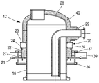
도 1에서 볼 수 있는 바와 같이, 저장 설비(71)는 천장 벽(8) 및 상부 지지 벽(9)에 생성된 개구(14, 15)를 통과하는 2개의 관통 구조체(12, 13)를 포함한다. 제1 관통 구조체는 제1 개구(14)를 관통하는 돔 구조체(12)이고, 제2 관통 구조체는 제2 개구(15)를 관통하는 맨홀 구조체다. 제1 개구(14) 및 제2 개구(15)는 도 1에 도시된 바와 같이 서로 이격되어 있다. As can be seen in FIG. 1 , the
돔 구조체(12)는 특히 액화가스 적재 및 하역 덕트(14, 15)를 위한 천장 벽(8)의 긴밀한 교차를 제공하는 것을 가능하게 한다. 맨홀 구조체(13)는 그 부분에 대해, 예를 들어 수리 작업을 위해 탱크(1)의 내부 공간(7)으로 이어지는 작업자의 접근을 유지하는 것을 가능하게 한다.The
따라서, 적재 덕트(14) 및 하역 덕트(15)는 그로부터 액화가스를 적재 또는 하역하기 위해 탱크(1)의 내부 공간(7)에 드러난다. 또한, 도 1에서 볼 수 있는 바와 같이, 바닥 벽(10)에 고정되며, 돔 구조체(12)의 축에서 적재 및 하역 덕트(14, 15)를 유지하도록 적재 덕트(14)의 단부 및 하역 덕트(15)의 단부를 둘러싸는 안내 장치(17)가 제공되는 지지 풋(16)이 제공된다.Accordingly, the loading duct 14 and the unloading duct 15 are exposed in the
관통 구조체(12, 13) 및 특히 지지 구조체(3)에 대한 관통 구조체의 고정은 이하에서 더 상세히 설명될 것이다.The fastening of the penetrating
도 2 및 도 3은 돔 구조체(12)를 보다 상세하게 나타내는 반면, 도 4 및 도 5는 맨홀 구조체(13)를 보다 상세하게 나타낸다.2 and 3 show the
아래에서 설명되는 관통 구조체, 즉 돔 구조체(12) 및 맨홀 구조체(13)는 실질적으로 유사한 구조를 가지며, 이들의 용도, 이들을 통과하는 요소 및 잠재적으로 이들의 치수에 의해서만 서로 상이하다. 또한, 맨홀 구조체(13)는 돔 구조체(12)와 달리 탈착 가능한 커버가 구비된다. The penetrating structures described below, ie the
따라서, 관통 구조체(12, 13)는 벽의 두께 방향으로 연장되고 상부 지지 벽(9) 및 천장 벽(8)을 통과하는 내부 배럴(18)을 포함한다. 내부 배럴(18)은 원형 단면을 갖는 원통형 형태이다. 내부 배럴(18)은 1차 밀폐 멤브레인(6)에 긴밀하게 용접되고 고정 장치(19)에 의해 상부 지지 벽(9)에 용접된다. Thus, the penetrating
고정 장치(19)는 다음을 포함한다:
The fixing
- 상부 지지 벽(9)의 외부에 배치되고 내부 배럴(18)의 주위에 용접되는 고정 링(20), - a retaining ring (20) arranged on the outside of the upper support wall (9) and welded to the periphery of the inner barrel (18);
- 내부 배럴(18)의 주위에 내부 배럴(18)에서 이격되어 방사상으로 연장되며, 개구(23)의 주위에서 상부 지지 벽(9)에 용접되는 고정 칼라(21),
- a
- 내부 배럴(18)의 주위에서 연장되고 한편으로는 고정 칼라(21)에 용접되고 다른 한편으로는 고정 링(20)에 용접되어 내부 배럴(18)의 지지를 보장하는 지지 외부 튜브(22).- a supporting
고정 장치(19)는 내부 배럴(18)의 반경 방향 및 길이 방향 수축을 가능하게 한다. 실제로, 예를 들어 그 안에 액화가스의 통로와 연결된 내부 배럴(18)의 수축 시, 고정 장치(19)는 상부 지지 벽(9), 용접부 또는 내부 배럴(18)에 대한 응력을 제한하도록 자체 변형함으로써 내부 배럴(18)의 변형을 따른다. The securing
도 2 내지 도 5에서 알 수 있는 바와 같이, 고정 링(20)은 내부 배럴(18)의 주위 전체에 형성되고 용접되는 내부 고리형 플레이트(24) 및 외부 고리형 플레이트(25)를 포함한다. 고리형 플레이트(24)는 고정 칼라(21)에 평행한 평면에 위치되며, 서로 이격된다. 외부 튜브(22)의 일단은 내부 고리형 플레이트(24)에 용접된다. 고정 링(20)은 한편으로는 내부 고리형 플레이트(24)에 고정되고 다른 한편으로는 외부 고리형 플레이트(25)에 고정되는 보강재(26)를 추가로 포함한다. 예를 들어 보강재(26)는 고리형 플레이트(24, 25)에 직교하는 평면에 형성된 플레이트이며, 보강재의 일측은 내부 배럴(18)과 접촉한다. 보강재(26)는 고정 링(20)을 보강하기 위해 내부 배럴(18)의 주위 전체에 분포된다. 2-5 , the retaining
고정 칼라(21)는 개구(23)와 접하는 적어도 하나의 지지 금속 시트와 동일한 평면에 형성된 평평한 플레이트로 구성되고, 상부 지지 벽(9) 상에 적어도 하나의 지지 금속 시트에 용접된다. 고정 칼라(21)는 고리형이며 상부 지지 벽(9)에 용접된 외부 윤곽과 내부 배럴(18)로부터 이격되어 위치하는 내부 윤곽을 포함한다. 외부 튜브(22)는 내부 윤곽으로부터 이격되어 고정 칼라(21)에 용접되어, 고정 칼라 부분(27)이 내부 배럴(18)을 향해 외부 튜브(22) 상에서 돌출된다. 이는 고정 칼라(21) 상의 외부 튜브(22)의 용접을 용이하게 하는 것을 가능하게 한다. The fixing
상부 지지 벽(9)에 대한 고정 칼라(21)의 고정을 돕기 위해, 지지 탭(39)은 고정 칼라(21)의 주위 전체에 고정되고, 관통 구조체(12, 13)의 고정 시에 상부 지지 벽(9)에 위치하기 위해 고정 칼라(21)의 외부 윤곽으로부터 내부 배럴(18)의 반대 방향으로 돌출된다.To assist in fixing the fixing
돔 구조체(12)의 특정 특징과 관련하여, 돔 구조체는 도 2 및 3에 더 자세히 도시되어 있다. 돔 구조체(12)는 탱크(1) 밖으로 돌출된 내부 배럴(18)의 단부에 용접된 돔형 천장(28)을 포함한다. 따라서, 돔 구조체(12)의 경우, 천장(28)과 내부 배럴(18)은 고정 후에 서로 분리될 수 없다. 내부 배럴(18) 및 천장(28)은 탱크(1)의 단열과 열적 연속성을 형성하기 위해 상부 지지 벽으로부터 돌출된 그것들의 외부 표면에 단열 패킹(40)으로 덮여 있다.With regard to certain features of the
도 1 내지 도 3에 도시된 실시예에서, 돔 구조체(12)는 액화가스 적재 덕트(29) 및 액화가스 하역 덕트(30)를 포함한다. 하역 덕트(30)는 탱크(1)의 내부 공간(7)에 도달하기 위해 천장(28)을 통과하여 내부 배럴(18)의 내부로 계속된다. 적재 덕트(29)는 탱크의 내부 공간(7)에 도달하기 위해 내부 배럴(18)을 통과하여 내부 배럴(18)의 내부로 계속된다. 이 실시예에서, 돔 구조체는 또한 탱크(1) 내의 액화가스의 레벨을 측정하는 것을 가능하게 하는 레벨 센서(34)와, 안전 덕트(42)를 포함할 수 있다. 1 to 3 , the
도시되지 않은 다른 실시예에서, 돔 구조체(12)는 레벨 센서 및 안전 덕트 대신에, 내부 공간(7)을 냉각하기 위해 탱크(1)의 적재 전에 탱크(1)로 액화가스를 분무하는 것을 가능하게 하는 액화가스 분무 시스템과, 예를 들어 선박의 추진 시스템 또는 재액화 장치로 증기 상태의 가스를 가져오기 위해 내부 공간(7)으로부터 증기 상태의 가스를 배출하는 것을 가능하게 하는 증기 배출 덕트를 포함할 수 있다.In another embodiment, not shown, the
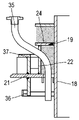
맨홀 구조체(13)의 특정 특징과 관련하여, 맨홀 구조체(13)는 2개의 변형 실시예에 따라 도 4 및 5에 더 상세히 도시되어 있다. 맨홀 구조체(13)는, 예를 들어 볼트 체결 방식으로 형성된 고정 시스템(31)을 사용하여 탱크(1) 외부로 돌출된 내부 배럴(18)의 단부에 제거 가능하게 고정된 돔형 천장(28)을 포함한다. 따라서, 맨홀 구조체(13)의 경우, 천장(28)은 내부 배럴(18)에 위치된 맨홀 구조체(13)의 커버를 형성한다.With regard to certain features of the
도 4에 도시된 실시예에서, 맨홀 구조체(13)는 내부 공간(7)을 냉각하기 위해 탱크(1)의 적재 전에 탱크(1)에 액화가스를 분무하는 것을 가능하게 하는 액화가스 분무 시스템(32)과, 예를 들어 선박의 추진 시스템 또는 재액화 유닛으로 증기 상태의 가스를 가져오기 위해 내부 공간(7)으로부터 증기 상태의 가스를 배출하는 것을 가능하게 하는 증기 배출 덕트(33)를 포함할 수 있다. 분무 시스템(32) 및 증기 배출 덕트(33)는 천장(28)에 고정되어 통과하고, 내부 배럴(18)에서 계속되어 탱크(1)의 내부 공간(7)에 도달한다. 예를 들어 수리 중에 천장(28)을 제거할 때 분무 시스템(32) 및 증기 배출 덕트(33)도 제거된다.In the embodiment shown in FIG. 4 , the
도 5에 도시된 실시예에서, 맨홀 구조체(13)는 탱크(1) 내의 액화가스의 레벨을 측정하는 것을 가능하게 하는 레벨 센서(34) 및 안전 덕트(도시되지 않음)를 포함한다. 레벨 센서(34)는 천장(28)을 통과하고 부분적으로 내부 배럴(18)의 내부에 위치한다. 레벨 센서(34)는 예를 들어 탱크(1)의 바닥을 향하는 광학 센서이다. 예를 들어 수리 중에 천장(28)을 제거할 때 레벨 센서(34)도 제거된다. In the embodiment shown in FIG. 5 , the
액화가스 탱크(1)의 단열 배리어(2, 5)는 특히 불활성 가스를 불활성화하고/하거나 밀폐 멤브레인(4, 6) 중 하나의 누출을 감지하기 위해, 질소와 같은 불활성 가스에 의해 통과된다. 이 불활성 가스를 이러한 배리어(2, 5) 내부에 추가하기 위해, 저장 설비(71)는 도 5 및 6에 도시된 바와 같이 고정 장치(19)를 통과하는 적어도 하나의 불활성 가스 유입 덕트(35)를 포함한다.The insulating
도 6에 도시된 변형예에서, 불활성 가스 유입 덕트(35)는 내부 고리형 플레이트(24) 및 고정 칼라 부분(27)에서 고정 장치(19)를 통과하는 반면, 도 7에 도시된 변형예에서 불활성 가스 유입 덕트(35)는 외부 튜브(22) 및 고정 칼라 부분(27)에서 고정 장치(19)를 통과한다. In the variant shown in FIG. 6 , the inert
도 6은 또한 1차 밀폐 멤브레인(6) 및 2차 밀폐 멤브레인(4)의 폐쇄가 관통 구조체(12, 13)에서 어떻게 생성되는지 설명하는 것을 가능하게 한다.6 also makes it possible to explain how the closure of the
실제로, 2차 밀폐 멤브레인(4)은 내부 배럴(18)에서 이격되어 차단되고 내부 배럴(18)의 주위 전체의 연결 링(36)을 통해 고정 칼라(21)에 고정된다. 따라서 2차 밀폐 멤브레인(4)은 내부 배럴(18)의 주위 전체의 연결 링(36)에 용접된다. In practice, the secondary
또한, 원형 보강재(37)가 고정 칼라(21)의 외부 표면으로부터 돌출된다. 도시된 실시예에서, 원형 보강재(37)는 연결 링(18)의 연장으로 연장된다.Also, a
1차 밀폐 멤브레인(6)은 또한 내부 배럴(18)에서 이격되어 차단된다. 관통 구조체(12, 13)는 탱크(1)의 내부 공간(7)에 위치하고 내부 배럴(18)의 주위 전체에 용접된 연결 칼라(38)를 포함한다. 1차 밀폐 멤브레인(6)은 연결 칼라(38)의 주위 전체에서 연결 칼라(38)에 직접 용접된다. 도시되지 않은 다른 실시예에서, 1차 밀폐 멤브레인(6)은 연결 플레이트를 통해 연결 칼라(38)에 용접될 수 있다.The primary
도 6에서, 2차 단열 배리어(2) 및 1차 단열 배리어(5)의 단열 요소가 개략적으로 도시되어 있다. 이러한 단열 요소는 예를 들어 합판으로 만들어진 상부 시트 및/또는 합판 바닥 시트가 고정될 수 있는 섬유 강화 폴리우레탄 폼과 같은 폴리머 폼 층에 의해 형성될 수 있다.In FIG. 6 , the insulating elements of the secondary
치수 예: Dimension example:
- 내부 배럴(18)의 직경: 약 1160 mm - Diameter of inner barrel (18): approx. 1160 mm
- 탱크(1) 외부의 돔 구조체(12)의 돌출 높이: 약 1420 mm,- the protrusion height of the
- 탱크(1) 외부의 맨홀 구조체(13)의 돌출 높이: 약 1400 mm, - the protrusion height of the manhole structure (13) outside the tank (1): about 1400 mm;
- 고정 칼라(21)의 외경: 약 1970 mm.- Outer diameter of fixing collar 21: approx. 1970 mm.
도 8을 참조하면, 메탄 선박(70)의 단면도는 선박의 이중 선체(72)에 장착된 일반적으로 프리즘 형태의 밀폐 및 단열된 탱크(1)를 도시한다. 이중 선체(72)는 내부 선체 및 외부 선체를 포함한다. 탱크(1)의 벽은 탱크에 포함된 LNG와 접촉하도록 되어 있는 1차 밀폐 멤브레인, 1차 밀폐 멤브레인과 선박의 이중 선체(72) 사이에 배치된 2차 밀폐 멤브레인, 및 1차 밀폐 멤브레인과 2차 밀폐 멤브레인 사이 그리고 2차 밀폐 멤브레인과 이중 선체(72) 사이에 각각 배치되는 2개의 단열 배리어를 포함한다.Referring to FIG. 8 , a cross-sectional view of a
그 자체로 알려진 바와 같이, 선박의 상부 데크에 배치된 적재/하역 파이프라인(73)은 탱크(1)로부터 또는 탱크(1)로 LNG 화물을 이송하기 위해 적절한 커넥터를 통해 해상 또는 항구 터미널에 연결될 수 있다. As is known per se, a loading/
도 8은 적재 및 하역 스테이션(75), 해저 덕트(76) 및 육상 설비(77)를 포함하는 해상 터미널의 예를 나타낸다. 적재 및 하역 스테이션(75)은 이동식 암(74) 및 이동식 암(74)을 지지하는 라이저(78: riser)를 포함하는 고정 해양 설비이다. 이동식 암(74)은 적재/하역 파이프라인(73)에 연결될 수 있는 단열된 가요성 파이프(79)의 번들을 지지한다. 지향성 이동식 암(74)은 모든 메탄 선박 템플릿에 적용된다. 표시되지 않은 링크 덕트는 라이저(78) 내부로 확장된다. 적재 및 하역 스테이션(75)은 육상 설비(77)로부터 또는 육상 설비(77)로 메탄 선박(70)의 적재 및 하역을 허용한다. 후자는 액화가스 저장 탱크(80) 및 해저 덕트(76)에 의해 적재 또는 하역 스테이션(75)에 연결된 링크 덕트(81)를 포함한다. 해저 덕트(76)는 액화가스가 적재 또는 하역 스테이션(75)과 육상 설비(77) 사이에서 먼 거리, 예를 들어 5km에 걸쳐 이송되도록 하여 적재 및 하역 작업 중 메탄 선박(70)를 해안으로부터 먼 거리에 유지하는 것을 가능하게 한다. 8 shows an example of an offshore terminal comprising a loading and unloading
액화가스의 이송에 필요한 압력을 생성하기 위해 선박(70)에 내장된 펌프 및/또는 육상 설비(77)가 구비된 펌프 및/또는 적재 및 하역 스테이션(75)이 구비된 펌프가 구현된다.A pump with a pump built into the
본 발명은 몇 가지 특정한 실시예와 관련하여 설명되었으나, 이에 제한되는 것은 아니며, 후자가 본 발명의 틀에 속하는 경우, 기재된 수단의 기술적 등가물 및 이들의 조합을 모두 포함하는 것은 매우 명백하다.While the present invention has been described with reference to several specific embodiments, it is not intended to be limited thereto, and it is very clear that the latter includes both technical equivalents of the described means and combinations thereof, provided they fall within the framework of the present invention.
동사 "구성하다" 또는 "포함하다"의 사용과 그 활용 형태는 청구항에 명시된 것 이외의 요소 또는 단계의 존재를 배제하지 않는다. The use of the verbs "comprise" or "comprise" and their conjugations do not exclude the presence of elements or steps other than those specified in a claim.
청구범위에서 괄호 사이의 참조 기호는 청구 범위를 제한하는 것으로 해석되어서는 안 된다.Reference signs between parentheses in the claims should not be construed as limiting the claims.
Claims (17)
상기 천장 벽(8)은 상기 탱크(1)의 외부에서 내부를 향해 두께 방향으로, 적어도 하나의 단열 배리어(2, 5)와 상기 단열 배리어(2, 5)에 의해 지지되고 상기 탱크(1)에 포함된 유체와 접촉하도록 되어 있는 적어도 하나의 밀폐 멤브레인(4, 6)을 포함하고,
상기 저장 설비(71)는 상기 천장 벽(8)과 상기 상부 지지 벽(9)에 생성된 개구(23)를 통과하는 관통 구조체(12, 13)를 포함하고,
상기 관통 구조체(12, 13)는 상기 두께 방향으로 연장되며 상기 상부 지지 벽(9)과 상기 천장 벽(8)을 통과하는 내부 배럴(18)을 포함하고, 상기 내부 배럴(18)은 상기 밀폐 멤브레인에 긴밀하게 용접되며 고정 장치(19)에 의해 상기 상부 지지 벽(9)에 고정되고,
상기 고정 장치(19)는
- 상기 지지 구조체(3)의 상기 상부 지지 벽(9)의 외부에 배치되며 상기 내부 배럴(18)의 주위에 용접되는 고정 링(20),
- 상기 내부 배럴(18)의 주위에 상기 내부 배럴(18)에서 이격되어 방사상으로 연장되고, 상기 지지 구조체(3)의 상기 상부 지지 벽(9)에 대해 상기 개구의 주위에 용접되는 고정 칼라(21: collar),
- 상기 내부 배럴(18)의 지지를 보장하기 위해 상기 내부 배럴(18)의 주위에 연장되며 한편으로는 상기 고정 칼라(21)에 용접되고 다른 한편으로는 상기 고정 링(20)에 용접되는 지지 외부 튜브(22)를 포함하고, 상기 고정 장치(19)는 상기 내부 배럴(18)의 반경 방향 및 길이 방향 수축을 허용하는, 저장 설비(71).A storage arrangement (71) for liquefied gas comprising a support structure (3) and a sealed and insulated tank (1) arranged on the support structure (3), the support structure (3) comprising an upper support wall (9) and the tank (1) comprises a ceiling wall (8), the ceiling wall (8) being fixed to the upper support wall (9) of the support structure (3),
The ceiling wall (8) is supported by at least one insulating barrier (2, 5) and the insulating barrier (2, 5) in the thickness direction from the outside to the inside of the tank (1) and the tank (1) at least one hermetic membrane (4, 6) adapted to come into contact with the fluid contained in the
The storage arrangement (71) comprises penetrating structures (12, 13) passing through openings (23) created in the ceiling wall (8) and the upper support wall (9),
The penetrating structure (12, 13) includes an inner barrel (18) extending in the thickness direction and passing through the upper support wall (9) and the ceiling wall (8), the inner barrel (18) is the sealing tightly welded to the membrane and fixed to the upper support wall (9) by means of a fastening device (19);
The fixing device 19 is
- a retaining ring (20) arranged outside the upper support wall (9) of the support structure (3) and welded around the inner barrel (18);
- a fixing collar extending radially away from the inner barrel 18 around the inner barrel 18 and welded around the opening to the upper support wall 9 of the support structure 3; 21: collar),
- a support extending around the inner barrel 18 and welded to the fastening collar 21 on the one hand and to the retaining ring 20 on the other hand to ensure support of the inner barrel 18 storage arrangement (71) comprising an outer tube (22), wherein said securing device (19) allows radial and longitudinal retraction of said inner barrel (18).
Applications Claiming Priority (2)
| Application Number | Priority Date | Filing Date | Title |
|---|---|---|---|
| FRFR2104511 | 2021-04-29 | ||
| FR2104511A FR3122477B1 (en) | 2021-04-29 | 2021-04-29 | Storage facility for liquefied gas |
Publications (1)
| Publication Number | Publication Date |
|---|---|
| KR20220149441A true KR20220149441A (en) | 2022-11-08 |
Family
ID=76601374
Family Applications (1)
| Application Number | Title | Priority Date | Filing Date |
|---|---|---|---|
| KR1020220051379A KR20220149441A (en) | 2021-04-29 | 2022-04-26 | Storage installation for liquefied gas |
Country Status (6)
| Country | Link |
|---|---|
| EP (1) | EP4083494A1 (en) |
| JP (1) | JP2022171607A (en) |
| KR (1) | KR20220149441A (en) |
| CN (1) | CN115264367A (en) |
| FR (2) | FR3122477B1 (en) |
| TW (1) | TW202303032A (en) |
Family Cites Families (15)
| Publication number | Priority date | Publication date | Assignee | Title |
|---|---|---|---|---|
| NL124440C (en) * | 1956-05-07 | |||
| US3326141A (en) * | 1963-11-26 | 1967-06-20 | Gen Am Transport | Heat-insulated railway tank cars |
| JPS6119592U (en) * | 1984-07-09 | 1986-02-04 | 石川島播磨重工業株式会社 | Manhole structure of double shell tank |
| DE3836071A1 (en) * | 1988-07-06 | 1990-01-18 | Lga Gastechnik Gmbh | Horizontal pressure tank for storing liquefied gases |
| FR2691520B1 (en) | 1992-05-20 | 1994-09-02 | Technigaz Ste Nle | Prefabricated structure for forming watertight and thermally insulating walls for containment of a fluid at very low temperature. |
| FR2877638B1 (en) | 2004-11-10 | 2007-01-19 | Gaz Transp Et Technigaz Soc Pa | THERMALLY INSULATED AND THERMALLY INSULATED TANK WITH COMPRESSION-RESISTANT CALORIFIC ELEMENTS |
| FR2996520B1 (en) | 2012-10-09 | 2014-10-24 | Gaztransp Et Technigaz | SEALED AND THERMALLY INSULATING TANK COMPRISING A METALIC MEMBRANE WOUNDED ACCORDING TO ORTHOGONAL PLATES |
| KR101447872B1 (en) * | 2012-10-22 | 2014-10-07 | 삼성중공업 주식회사 | Gas passage way structure |
| KR20140088975A (en) | 2012-12-31 | 2014-07-14 | 대우조선해양 주식회사 | Recess type gas dome structure |
| KR101359537B1 (en) * | 2013-01-18 | 2014-02-13 | 삼성중공업 주식회사 | Installation structure of pump tower and method of welding thereof |
| FR3052843B1 (en) * | 2016-06-15 | 2018-07-06 | Gaztransport Et Technigaz | GAS DOME STRUCTURE FOR A SEALED AND THERMALLY INSULATING TANK |
| KR20180065263A (en) * | 2016-12-07 | 2018-06-18 | 대우조선해양 주식회사 | Gas dome spray apparatus of lng storage tank |
| FR3062703B1 (en) * | 2017-02-09 | 2020-10-02 | Gaztransport Et Technigaz | GAS DOME STRUCTURE FOR A WATERPROOF AND THERMALLY INSULATION TANK |
| FR3069904B1 (en) * | 2017-08-07 | 2020-10-02 | Gaztransport Et Technigaz | WATERPROOF AND THERMALLY INSULATION CONTAINING A GAS DOME STRUCTURE |
| JP2019039440A (en) | 2017-08-22 | 2019-03-14 | 三井E&S造船株式会社 | Liquefied gas storage tank structure, floating structure, and release method for internal pressure of storage tank |
-
2021
- 2021-04-29 FR FR2104511A patent/FR3122477B1/en active Active
- 2021-06-30 FR FR2107049A patent/FR3122476B1/en active Active
-
2022
- 2022-04-22 EP EP22169558.8A patent/EP4083494A1/en active Pending
- 2022-04-26 KR KR1020220051379A patent/KR20220149441A/en unknown
- 2022-04-26 JP JP2022072520A patent/JP2022171607A/en active Pending
- 2022-04-27 CN CN202210457042.2A patent/CN115264367A/en active Pending
- 2022-04-27 TW TW111116080A patent/TW202303032A/en unknown
Also Published As
| Publication number | Publication date |
|---|---|
| FR3122477B1 (en) | 2023-12-08 |
| FR3122477A1 (en) | 2022-11-04 |
| CN115264367A (en) | 2022-11-01 |
| FR3122476B1 (en) | 2024-04-05 |
| TW202303032A (en) | 2023-01-16 |
| FR3122476A1 (en) | 2022-11-04 |
| EP4083494A1 (en) | 2022-11-02 |
| JP2022171607A (en) | 2022-11-11 |
Similar Documents
| Publication | Publication Date | Title |
|---|---|---|
| CN109416150B (en) | Gas dome construction for sealed insulated tank | |
| JP7229259B2 (en) | Equipment for storing and transporting liquefied gas | |
| KR102029862B1 (en) | Vessel wall comprising a pipe | |
| CN108413244B (en) | Gas dome for sealing an insulated tank | |
| RU2759040C2 (en) | Sealed and heat-insulated tank containing a gas dome structure | |
| JP7408679B2 (en) | Closed insulated tank | |
| KR20180133861A (en) | Thermal sealing tank | |
| KR20220125329A (en) | Liquefied gas storage facility | |
| KR20220149473A (en) | Storage facility for liquefied gas | |
| JP2023163168A (en) | Tank wall with through-duct | |
| KR20220149441A (en) | Storage installation for liquefied gas | |
| KR20230009428A (en) | Liquid dome of a storage tank for liquefied gas, having an opening with an additional hatch | |
| KR102596193B1 (en) | Systems for storing and transporting cryogenic fluids on board ships | |
| JP7419338B2 (en) | fluid storage equipment | |
| KR20230012570A (en) | Liquefied gas storage facility | |
| RU2817469C1 (en) | Liquefied gas storage | |
| RU2810174C2 (en) | Heat-insulated airtight tank | |
| KR20230093168A (en) | Facility for storing a liquefied gas comprising a tank and a dome structure | |
| KR20230153288A (en) | Tank wall traversed by a sealed fluid-discharge conduit | |
| KR20220090447A (en) | Ship including a tank | |
| KR20210083326A (en) | liquefied gas storage facility | |
| KR20230079433A (en) | airtight insulated tank | |
| KR20210152973A (en) | Tank wall for fluid-tight and thermally insulating tank | |
| KR20210085637A (en) | Gas dome structure and liquefied gas storage tank having the same |