KR20200055735A - Clutch-based adjustment mechanism for electric multi-way seat adjustment - Google Patents
Clutch-based adjustment mechanism for electric multi-way seat adjustment Download PDFInfo
- Publication number
- KR20200055735A KR20200055735A KR1020207009869A KR20207009869A KR20200055735A KR 20200055735 A KR20200055735 A KR 20200055735A KR 1020207009869 A KR1020207009869 A KR 1020207009869A KR 20207009869 A KR20207009869 A KR 20207009869A KR 20200055735 A KR20200055735 A KR 20200055735A
- Authority
- KR
- South Korea
- Prior art keywords
- seat
- gear wheel
- wheel
- adjustment
- adjustment mechanism
- Prior art date
Links
- 230000007246 mechanism Effects 0.000 title claims abstract description 130
- 230000033001 locomotion Effects 0.000 claims description 38
- 238000006073 displacement reaction Methods 0.000 claims description 33
- 229910001285 shape-memory alloy Inorganic materials 0.000 claims description 17
- 238000000034 method Methods 0.000 claims description 15
- 230000000295 complement effect Effects 0.000 description 45
- 230000013011 mating Effects 0.000 description 24
- 230000008878 coupling Effects 0.000 description 9
- 238000010168 coupling process Methods 0.000 description 9
- 238000005859 coupling reaction Methods 0.000 description 9
- 230000007935 neutral effect Effects 0.000 description 9
- 239000012636 effector Substances 0.000 description 3
- 230000004044 response Effects 0.000 description 3
- 229920000742 Cotton Polymers 0.000 description 2
- 230000000694 effects Effects 0.000 description 2
- 238000010438 heat treatment Methods 0.000 description 2
- 238000006243 chemical reaction Methods 0.000 description 1
- 238000001816 cooling Methods 0.000 description 1
- 230000001419 dependent effect Effects 0.000 description 1
- 229920002457 flexible plastic Polymers 0.000 description 1
- 238000009434 installation Methods 0.000 description 1
- NJPPVKZQTLUDBO-UHFFFAOYSA-N novaluron Chemical compound C1=C(Cl)C(OC(F)(F)C(OC(F)(F)F)F)=CC=C1NC(=O)NC(=O)C1=C(F)C=CC=C1F NJPPVKZQTLUDBO-UHFFFAOYSA-N 0.000 description 1
- 238000004904 shortening Methods 0.000 description 1
- 239000013589 supplement Substances 0.000 description 1
Images


Classifications
-
- B—PERFORMING OPERATIONS; TRANSPORTING
- B60—VEHICLES IN GENERAL
- B60N—SEATS SPECIALLY ADAPTED FOR VEHICLES; VEHICLE PASSENGER ACCOMMODATION NOT OTHERWISE PROVIDED FOR
- B60N2/00—Seats specially adapted for vehicles; Arrangement or mounting of seats in vehicles
- B60N2/02—Seats specially adapted for vehicles; Arrangement or mounting of seats in vehicles the seat or part thereof being movable, e.g. adjustable
- B60N2/0224—Non-manual adjustments, e.g. with electrical operation
- B60N2/02246—Electric motors therefor
- B60N2/02258—Electric motors therefor characterised by the mounting of the electric motor for adjusting the seat
-
- B60N2/0232—
-
- B—PERFORMING OPERATIONS; TRANSPORTING
- B60—VEHICLES IN GENERAL
- B60N—SEATS SPECIALLY ADAPTED FOR VEHICLES; VEHICLE PASSENGER ACCOMMODATION NOT OTHERWISE PROVIDED FOR
- B60N2/00—Seats specially adapted for vehicles; Arrangement or mounting of seats in vehicles
- B60N2/02—Seats specially adapted for vehicles; Arrangement or mounting of seats in vehicles the seat or part thereof being movable, e.g. adjustable
- B60N2/0224—Non-manual adjustments, e.g. with electrical operation
- B60N2/02246—Electric motors therefor
- B60N2/02253—Electric motors therefor characterised by the transmission between the electric motor and the seat or seat parts
-
- B—PERFORMING OPERATIONS; TRANSPORTING
- B60—VEHICLES IN GENERAL
- B60N—SEATS SPECIALLY ADAPTED FOR VEHICLES; VEHICLE PASSENGER ACCOMMODATION NOT OTHERWISE PROVIDED FOR
- B60N2/00—Seats specially adapted for vehicles; Arrangement or mounting of seats in vehicles
- B60N2/02—Seats specially adapted for vehicles; Arrangement or mounting of seats in vehicles the seat or part thereof being movable, e.g. adjustable
- B60N2/0284—Adjustable seat-cushion length
-
- B—PERFORMING OPERATIONS; TRANSPORTING
- B60—VEHICLES IN GENERAL
- B60N—SEATS SPECIALLY ADAPTED FOR VEHICLES; VEHICLE PASSENGER ACCOMMODATION NOT OTHERWISE PROVIDED FOR
- B60N2/00—Seats specially adapted for vehicles; Arrangement or mounting of seats in vehicles
- B60N2/02—Seats specially adapted for vehicles; Arrangement or mounting of seats in vehicles the seat or part thereof being movable, e.g. adjustable
- B60N2/22—Seats specially adapted for vehicles; Arrangement or mounting of seats in vehicles the seat or part thereof being movable, e.g. adjustable the back-rest being adjustable
- B60N2/23—Seats specially adapted for vehicles; Arrangement or mounting of seats in vehicles the seat or part thereof being movable, e.g. adjustable the back-rest being adjustable by linear actuators, e.g. linear screw mechanisms
- B60N2/233—Seats specially adapted for vehicles; Arrangement or mounting of seats in vehicles the seat or part thereof being movable, e.g. adjustable the back-rest being adjustable by linear actuators, e.g. linear screw mechanisms by linear screw mechanisms
-
- B—PERFORMING OPERATIONS; TRANSPORTING
- B60—VEHICLES IN GENERAL
- B60N—SEATS SPECIALLY ADAPTED FOR VEHICLES; VEHICLE PASSENGER ACCOMMODATION NOT OTHERWISE PROVIDED FOR
- B60N2/00—Seats specially adapted for vehicles; Arrangement or mounting of seats in vehicles
- B60N2/62—Thigh-rests
-
- B—PERFORMING OPERATIONS; TRANSPORTING
- B60—VEHICLES IN GENERAL
- B60N—SEATS SPECIALLY ADAPTED FOR VEHICLES; VEHICLE PASSENGER ACCOMMODATION NOT OTHERWISE PROVIDED FOR
- B60N2/00—Seats specially adapted for vehicles; Arrangement or mounting of seats in vehicles
- B60N2/64—Back-rests or cushions
- B60N2/66—Lumbar supports
- B60N2/666—Lumbar supports vertically adjustable
-
- B—PERFORMING OPERATIONS; TRANSPORTING
- B60—VEHICLES IN GENERAL
- B60N—SEATS SPECIALLY ADAPTED FOR VEHICLES; VEHICLE PASSENGER ACCOMMODATION NOT OTHERWISE PROVIDED FOR
- B60N2/00—Seats specially adapted for vehicles; Arrangement or mounting of seats in vehicles
- B60N2/80—Head-rests
- B60N2/806—Head-rests movable or adjustable
- B60N2/809—Head-rests movable or adjustable vertically slidable
- B60N2/812—Head-rests movable or adjustable vertically slidable characterised by their locking devices
- B60N2/821—Head-rests movable or adjustable vertically slidable characterised by their locking devices with continuous positioning
-
- B—PERFORMING OPERATIONS; TRANSPORTING
- B60—VEHICLES IN GENERAL
- B60N—SEATS SPECIALLY ADAPTED FOR VEHICLES; VEHICLE PASSENGER ACCOMMODATION NOT OTHERWISE PROVIDED FOR
- B60N2/00—Seats specially adapted for vehicles; Arrangement or mounting of seats in vehicles
- B60N2/80—Head-rests
- B60N2/806—Head-rests movable or adjustable
- B60N2/809—Head-rests movable or adjustable vertically slidable
- B60N2/829—Head-rests movable or adjustable vertically slidable characterised by their adjusting mechanisms, e.g. electric motors
-
- B—PERFORMING OPERATIONS; TRANSPORTING
- B60—VEHICLES IN GENERAL
- B60N—SEATS SPECIALLY ADAPTED FOR VEHICLES; VEHICLE PASSENGER ACCOMMODATION NOT OTHERWISE PROVIDED FOR
- B60N2/00—Seats specially adapted for vehicles; Arrangement or mounting of seats in vehicles
- B60N2/80—Head-rests
- B60N2/806—Head-rests movable or adjustable
- B60N2/838—Tiltable
- B60N2/841—Tiltable characterised by their locking devices
- B60N2/85—Tiltable characterised by their locking devices with continuous positioning
-
- B—PERFORMING OPERATIONS; TRANSPORTING
- B60—VEHICLES IN GENERAL
- B60N—SEATS SPECIALLY ADAPTED FOR VEHICLES; VEHICLE PASSENGER ACCOMMODATION NOT OTHERWISE PROVIDED FOR
- B60N2/00—Seats specially adapted for vehicles; Arrangement or mounting of seats in vehicles
- B60N2/80—Head-rests
- B60N2/806—Head-rests movable or adjustable
- B60N2/838—Tiltable
- B60N2/853—Tiltable characterised by their adjusting mechanisms, e.g. electric motors
-
- B—PERFORMING OPERATIONS; TRANSPORTING
- B60—VEHICLES IN GENERAL
- B60N—SEATS SPECIALLY ADAPTED FOR VEHICLES; VEHICLE PASSENGER ACCOMMODATION NOT OTHERWISE PROVIDED FOR
- B60N2/00—Seats specially adapted for vehicles; Arrangement or mounting of seats in vehicles
- B60N2/80—Head-rests
- B60N2/806—Head-rests movable or adjustable
- B60N2/865—Head-rests movable or adjustable providing a fore-and-aft movement with respect to the occupant's head
-
- B—PERFORMING OPERATIONS; TRANSPORTING
- B60—VEHICLES IN GENERAL
- B60N—SEATS SPECIALLY ADAPTED FOR VEHICLES; VEHICLE PASSENGER ACCOMMODATION NOT OTHERWISE PROVIDED FOR
- B60N2/00—Seats specially adapted for vehicles; Arrangement or mounting of seats in vehicles
- B60N2/80—Head-rests
- B60N2/806—Head-rests movable or adjustable
- B60N2/868—Head-rests movable or adjustable providing a lateral movement parallel to the occupant's shoulder line
-
- B—PERFORMING OPERATIONS; TRANSPORTING
- B60—VEHICLES IN GENERAL
- B60N—SEATS SPECIALLY ADAPTED FOR VEHICLES; VEHICLE PASSENGER ACCOMMODATION NOT OTHERWISE PROVIDED FOR
- B60N2/00—Seats specially adapted for vehicles; Arrangement or mounting of seats in vehicles
- B60N2/80—Head-rests
- B60N2/885—Head-rests provided with side-rests
-
- B—PERFORMING OPERATIONS; TRANSPORTING
- B60—VEHICLES IN GENERAL
- B60N—SEATS SPECIALLY ADAPTED FOR VEHICLES; VEHICLE PASSENGER ACCOMMODATION NOT OTHERWISE PROVIDED FOR
- B60N2/00—Seats specially adapted for vehicles; Arrangement or mounting of seats in vehicles
- B60N2/90—Details or parts not otherwise provided for
- B60N2/919—Positioning and locking mechanisms
-
- F—MECHANICAL ENGINEERING; LIGHTING; HEATING; WEAPONS; BLASTING
- F16—ENGINEERING ELEMENTS AND UNITS; GENERAL MEASURES FOR PRODUCING AND MAINTAINING EFFECTIVE FUNCTIONING OF MACHINES OR INSTALLATIONS; THERMAL INSULATION IN GENERAL
- F16H—GEARING
- F16H25/00—Gearings comprising primarily only cams, cam-followers and screw-and-nut mechanisms
- F16H25/18—Gearings comprising primarily only cams, cam-followers and screw-and-nut mechanisms for conveying or interconverting oscillating or reciprocating motions
- F16H25/20—Screw mechanisms
-
- F—MECHANICAL ENGINEERING; LIGHTING; HEATING; WEAPONS; BLASTING
- F03—MACHINES OR ENGINES FOR LIQUIDS; WIND, SPRING, OR WEIGHT MOTORS; PRODUCING MECHANICAL POWER OR A REACTIVE PROPULSIVE THRUST, NOT OTHERWISE PROVIDED FOR
- F03G—SPRING, WEIGHT, INERTIA OR LIKE MOTORS; MECHANICAL-POWER PRODUCING DEVICES OR MECHANISMS, NOT OTHERWISE PROVIDED FOR OR USING ENERGY SOURCES NOT OTHERWISE PROVIDED FOR
- F03G7/00—Mechanical-power-producing mechanisms, not otherwise provided for or using energy sources not otherwise provided for
- F03G7/06—Mechanical-power-producing mechanisms, not otherwise provided for or using energy sources not otherwise provided for using expansion or contraction of bodies due to heating, cooling, moistening, drying or the like
- F03G7/061—Mechanical-power-producing mechanisms, not otherwise provided for or using energy sources not otherwise provided for using expansion or contraction of bodies due to heating, cooling, moistening, drying or the like characterised by the actuating element
- F03G7/0614—Mechanical-power-producing mechanisms, not otherwise provided for or using energy sources not otherwise provided for using expansion or contraction of bodies due to heating, cooling, moistening, drying or the like characterised by the actuating element using shape memory elements
-
- F—MECHANICAL ENGINEERING; LIGHTING; HEATING; WEAPONS; BLASTING
- F03—MACHINES OR ENGINES FOR LIQUIDS; WIND, SPRING, OR WEIGHT MOTORS; PRODUCING MECHANICAL POWER OR A REACTIVE PROPULSIVE THRUST, NOT OTHERWISE PROVIDED FOR
- F03G—SPRING, WEIGHT, INERTIA OR LIKE MOTORS; MECHANICAL-POWER PRODUCING DEVICES OR MECHANISMS, NOT OTHERWISE PROVIDED FOR OR USING ENERGY SOURCES NOT OTHERWISE PROVIDED FOR
- F03G7/00—Mechanical-power-producing mechanisms, not otherwise provided for or using energy sources not otherwise provided for
- F03G7/06—Mechanical-power-producing mechanisms, not otherwise provided for or using energy sources not otherwise provided for using expansion or contraction of bodies due to heating, cooling, moistening, drying or the like
- F03G7/065—Mechanical-power-producing mechanisms, not otherwise provided for or using energy sources not otherwise provided for using expansion or contraction of bodies due to heating, cooling, moistening, drying or the like using a shape memory element
-
- F—MECHANICAL ENGINEERING; LIGHTING; HEATING; WEAPONS; BLASTING
- F16—ENGINEERING ELEMENTS AND UNITS; GENERAL MEASURES FOR PRODUCING AND MAINTAINING EFFECTIVE FUNCTIONING OF MACHINES OR INSTALLATIONS; THERMAL INSULATION IN GENERAL
- F16D—COUPLINGS FOR TRANSMITTING ROTATION; CLUTCHES; BRAKES
- F16D11/00—Clutches in which the members have interengaging parts
- F16D11/14—Clutches in which the members have interengaging parts with clutching members movable only axially
-
- F—MECHANICAL ENGINEERING; LIGHTING; HEATING; WEAPONS; BLASTING
- F16—ENGINEERING ELEMENTS AND UNITS; GENERAL MEASURES FOR PRODUCING AND MAINTAINING EFFECTIVE FUNCTIONING OF MACHINES OR INSTALLATIONS; THERMAL INSULATION IN GENERAL
- F16H—GEARING
- F16H25/00—Gearings comprising primarily only cams, cam-followers and screw-and-nut mechanisms
- F16H25/18—Gearings comprising primarily only cams, cam-followers and screw-and-nut mechanisms for conveying or interconverting oscillating or reciprocating motions
- F16H25/20—Screw mechanisms
- F16H2025/2046—Screw mechanisms with gears arranged perpendicular to screw shaft axis, e.g. helical gears engaging tangentially the screw shaft
-
- F—MECHANICAL ENGINEERING; LIGHTING; HEATING; WEAPONS; BLASTING
- F16—ENGINEERING ELEMENTS AND UNITS; GENERAL MEASURES FOR PRODUCING AND MAINTAINING EFFECTIVE FUNCTIONING OF MACHINES OR INSTALLATIONS; THERMAL INSULATION IN GENERAL
- F16H—GEARING
- F16H25/00—Gearings comprising primarily only cams, cam-followers and screw-and-nut mechanisms
- F16H25/18—Gearings comprising primarily only cams, cam-followers and screw-and-nut mechanisms for conveying or interconverting oscillating or reciprocating motions
- F16H25/20—Screw mechanisms
- F16H2025/2062—Arrangements for driving the actuator
- F16H2025/2071—Disconnecting drive source from the actuator, e.g. using clutches for release of drive connection during manual control
-
- F—MECHANICAL ENGINEERING; LIGHTING; HEATING; WEAPONS; BLASTING
- F16—ENGINEERING ELEMENTS AND UNITS; GENERAL MEASURES FOR PRODUCING AND MAINTAINING EFFECTIVE FUNCTIONING OF MACHINES OR INSTALLATIONS; THERMAL INSULATION IN GENERAL
- F16H—GEARING
- F16H25/00—Gearings comprising primarily only cams, cam-followers and screw-and-nut mechanisms
- F16H25/18—Gearings comprising primarily only cams, cam-followers and screw-and-nut mechanisms for conveying or interconverting oscillating or reciprocating motions
- F16H25/20—Screw mechanisms
- F16H2025/2062—Arrangements for driving the actuator
- F16H2025/2081—Parallel arrangement of drive motor to screw axis
-
- F—MECHANICAL ENGINEERING; LIGHTING; HEATING; WEAPONS; BLASTING
- F16—ENGINEERING ELEMENTS AND UNITS; GENERAL MEASURES FOR PRODUCING AND MAINTAINING EFFECTIVE FUNCTIONING OF MACHINES OR INSTALLATIONS; THERMAL INSULATION IN GENERAL
- F16H—GEARING
- F16H25/00—Gearings comprising primarily only cams, cam-followers and screw-and-nut mechanisms
- F16H25/18—Gearings comprising primarily only cams, cam-followers and screw-and-nut mechanisms for conveying or interconverting oscillating or reciprocating motions
- F16H25/20—Screw mechanisms
- F16H2025/2062—Arrangements for driving the actuator
- F16H2025/2084—Perpendicular arrangement of drive motor to screw axis
-
- F—MECHANICAL ENGINEERING; LIGHTING; HEATING; WEAPONS; BLASTING
- F16—ENGINEERING ELEMENTS AND UNITS; GENERAL MEASURES FOR PRODUCING AND MAINTAINING EFFECTIVE FUNCTIONING OF MACHINES OR INSTALLATIONS; THERMAL INSULATION IN GENERAL
- F16H—GEARING
- F16H25/00—Gearings comprising primarily only cams, cam-followers and screw-and-nut mechanisms
- F16H25/18—Gearings comprising primarily only cams, cam-followers and screw-and-nut mechanisms for conveying or interconverting oscillating or reciprocating motions
- F16H25/20—Screw mechanisms
- F16H2025/2062—Arrangements for driving the actuator
- F16H2025/209—Arrangements for driving the actuator using worm gears
Landscapes
- Engineering & Computer Science (AREA)
- Mechanical Engineering (AREA)
- Aviation & Aerospace Engineering (AREA)
- Transportation (AREA)
- General Engineering & Computer Science (AREA)
- Seats For Vehicles (AREA)
- Chair Legs, Seat Parts, And Backrests (AREA)
- Gear Transmission (AREA)
Abstract
전동식 멀티-웨이 시트 조정을 위한 클러치-기반 조정 기구. 조정 기구는 복수의 스크류 샤프트(111, 112, 113) 및 스크류 샤프트를 구동하기 위한 모터(150)를 포함한다. 또한, 조정 기구는 모터(150)를 하나 이상의 스크류 샤프트(111, 112, 113)와 선택적으로 결합시키기 위한 클러치 기구(160)를 포함한다. 모터(150)에 의해 야기된 하나 이상의 스크류 샤프트(111, 12, 113)의 회전은 제1 자유도에 따른 시트의 조정으로 전환된다. 모터(150)에 의해 야기된 하나 이상의 다른 스크류 샤프트(111, 12, 113)의 회전은 제2 자유도에 따른 시트의 조정으로 전환된다.Clutch-based adjustment mechanism for electric multi-way seat adjustment. The adjustment mechanism includes a plurality of screw shafts 111, 112, 113 and a motor 150 for driving the screw shaft. In addition, the adjustment mechanism includes a clutch mechanism 160 for selectively engaging the motor 150 with one or more screw shafts 111, 112, 113. The rotation of the one or more screw shafts 111, 12, 113 caused by the motor 150 is converted to the adjustment of the seat according to the first degree of freedom. The rotation of one or more other screw shafts 111, 12, 113 caused by the motor 150 is converted to the adjustment of the seat according to the second degree of freedom.
Description
본 발명은 시트용 조정 기구 및 이러한 조정 기구가 장착된 시트에 관한 것이다. 본 발명은 특히 시트의 전동식 멀티-웨이 조정을 위한 조정 기구에 관한 것이다.The present invention relates to a seat adjustment mechanism and a seat on which the adjustment mechanism is mounted. The present invention particularly relates to an adjustment mechanism for electric multi-way adjustment of the seat.
시트의 안락함을 최적화하는 관점에서, 시트에 다양한 종류의 조정성을 제공하는 것이 알려져 있다. 예를 들어, 시트의 등받이부의 경사에 대해, 시트의 머리 받침대의 높이에 대해, 또는 시트의 요추 지지부의 아칭(arching) 및/또는 수직 위치에 대해 차량 시트를 조정하는 것이 알려져 있다.From the viewpoint of optimizing the comfort of the seat, it is known to provide the seat with various kinds of adjustability. For example, it is known to adjust the vehicle seat relative to the inclination of the backrest of the seat, the height of the headrest of the seat, or the arching and / or vertical position of the lumbar support of the seat.
시트의 조정을 용이하게 하기 위해, 전동 방식으로 시트의 조정을 구현하는 것이 또한 알려져 있다. 예를 들어, WO 2017/032390 A1호는 다양한 시트 구성 요소를 조정하기 위해 사용될 수 있는 전동식 조정 기구를 설명한다. EP 2 698 278 A1호는 머리 받침대를 전/후 방향으로 시프팅시키거나 머리 받침대의 측면 볼스터(bolster)의 위치를 조정하기 위해 사용될 수 있는 머리 받침대용 전동식 조정 기구를 설명한다.In order to facilitate the adjustment of the seat, it is also known to implement the adjustment of the seat in a motorized manner. For example, WO 2017/032390 A1 describes an electric adjustment mechanism that can be used to adjust various seat components. EP 2 698 278 A1 describes an electric adjustment mechanism for a headrest that can be used to shift the headrest forward / backward or to adjust the position of the side bolster of the headrest.
그러나, 이러한 알려진 조정 기구에서, 각각의 조정 자유도에 대해 별도의 조정 기구 및 모터가 제공될 필요가 있을 수 있다. 예를 들어, EP 2 698 278 A1호는 시트의 머리 받침대에서 2개의 별도의 액추에이터의 사용을 설명하며, 하나는 전/후 방향으로의 머리 받침대의 조정을 위해 제공되고, 다른 하나는 머리 받침대의 높이 조정을 위해 제공된다.However, in these known adjustment mechanisms, it may be necessary to provide separate adjustment mechanisms and motors for each adjustment degree of freedom. For example, EP 2 698 278 A1 describes the use of two separate actuators on the headrest of the seat, one provided for adjustment of the headrest in the forward / backward direction and the other It is provided for height adjustment.
따라서, 복수의 자유도에 따라 시트를 효율적으로 조정할 수 있게 하는 조정 기구에 대한 필요성이 존재한다.Therefore, there is a need for an adjustment mechanism that enables the sheet to be efficiently adjusted according to a plurality of degrees of freedom.
본 발명은 청구항 1에 따른 조정 기구 및 청구항 15에 따른 시트를 제공한다. 종속 청구항은 추가의 실시예를 규정한다.The invention provides an adjustment mechanism according to claim 1 and a seat according to claim 15. The dependent claims define further embodiments.
따라서, 실시예에 따른 조정 기구는 적어도 2개의 자유도에 따라 시트를 조정하기 위해 시트에 사용되는 목적을 갖는다. 이러한 자유도의 예는 측면 볼스터 또는 다리 지지부와 같은 하나 이상의 플랩 요소의 틸팅(tilting), 시트의 머리 받침대의 전/후 방향으로의 수평 이동, 시트의 머리 받침대의 수직 이동, 시트의 시트 쿠션부의 길이 조정, 시트의 요추 지지부의 높이 조정, 또는 시트의 요추 지지부의 아칭(arching)의 조정이다.Accordingly, the adjustment mechanism according to the embodiment has the purpose of being used in the seat to adjust the seat according to at least two degrees of freedom. Examples of such degrees of freedom include tilting of one or more flap elements, such as side bolsters or leg supports, horizontal movement of the seat's head rest in a forward / backward direction, vertical movement of the seat's head rest, and length of the seat cushion of the seat. Adjustment, height adjustment of the lumbar support of the seat, or adjustment of arching of the lumbar support of the seat.
실시예에 따르면, 조정 기구는 복수의 스크류 샤프트 및 스크류 샤프트를 구동하기 위한 모터를 포함한다. 또한, 조정 기구는 모터를 하나 이상의 스크류 샤프트와 선택적으로 결합시키기 위한 클러치 기구를 포함한다. 모터에 의해 야기된 하나 이상의 스크류 샤프트의 회전은 제1 자유도에 따른 시트의 조정으로 전환된다. 모터에 의해 야기된 하나 이상의 다른 스크류 샤프트의 회전은 제2 자유도에 따른 시트의 조정으로 전환된다. 따라서, 복수의 자유도가 단일 모터에 의해 효율적으로 지원될 수 있다. 제1 자유도 및 제2 자유도는 시트의 머리 받침대의 수평 방향으로 변위, 시트의 머리 받침대의 틸팅, 시트의 머리 받침대의 수직 변위, 시트의 적어도 하나의 플랩(flap) 요소의 틸팅, 시트의 요추 지지부의 수직 변위, 시트의 요추 지지부의 아칭의 조정 및 시트의 시트 쿠션부의 길이의 조정을 포함하는 그룹으로부터의 2개의 다른 자유도에 대응할 수 있다. 하나 이상의 너트 요소가 스크류 샤프트의 적어도 일부와 결합하여, 이들 스크류 샤프트의 회전이 너트 요소의 선형 이동으로 전환될 수 있고, 너트 요소의 이러한 선형 이동이 결국 제1 자유도에 따른 및/또는 제2 자유도에 따른 조정으로 전환될 수 있다.According to an embodiment, the adjustment mechanism includes a plurality of screw shafts and a motor for driving the screw shafts. In addition, the adjustment mechanism includes a clutch mechanism for selectively engaging the motor with one or more screw shafts. The rotation of one or more screw shafts caused by the motor is converted into adjustment of the seat according to the first degree of freedom. The rotation of one or more other screw shafts caused by the motor translates into adjustment of the seat according to the second degree of freedom. Thus, multiple degrees of freedom can be efficiently supported by a single motor. The first and second degrees of freedom are displaced in the horizontal direction of the headrest of the seat, tilting of the headrest of the seat, vertical displacement of the headrest of the seat, tilting of at least one flap element of the seat, lumbar vertebra of the seat It can correspond to two different degrees of freedom from the group including vertical displacement of the support, adjustment of the arching of the lumbar support of the seat and adjustment of the length of the seat cushion of the seat. One or more nut elements may engage with at least a portion of the screw shaft, such that rotation of these screw shafts can be converted to linear movement of the nut elements, such linear movement of the nut elements eventually resulting in a first degree of freedom and / or a second degree of freedom. It can be converted into the adjustment according to.
실시예에 따르면, 조정 기구는 스크류 샤프트 중 하나의 구동 샤프트 상에, 구동 샤프트에 대해 회전 가능한 제1 휠 및 제1 휠과 선택적으로 결합될 수 있는 제2 휠을 포함한다. 이러한 방식으로, 제1 휠의 회전이 스크류 샤프트의 회전으로 전환되는지 여부가 효율적으로 제어될 수 있다.According to an embodiment, the adjustment mechanism comprises on the drive shaft of one of the screw shafts, a first wheel rotatable relative to the drive shaft and a second wheel selectively engageable with the first wheel. In this way, whether the rotation of the first wheel is switched to the rotation of the screw shaft can be efficiently controlled.
실시예에 따르면, 제1 휠 및 제2 휠 중 적어도 하나는 스크류 샤프트 중 다른 하나의 구동 샤프트 상의 기어 휠과 결합된 기어 휠이다. 이러한 방식으로, 클러치 기구는 하나의 스크류 샤프트를 다른 스크류 샤프트로부터 효율적으로 구동할 수 있게 하여, 결국 클러치 기구를 컴팩트한 방식으로 구현하는 것을 용이하게 한다.According to an embodiment, at least one of the first wheel and the second wheel is a gear wheel combined with a gear wheel on the drive shaft of the other of the screw shafts. In this way, the clutch mechanism makes it possible to efficiently drive one screw shaft from the other screw shaft, which in turn facilitates implementing the clutch mechanism in a compact manner.
실시예에 따르면, 제1 자유도는 시트의 머리 받침대의 수평 방향으로의 변위 또는 시트의 머리 받침대의 틸팅을 포함하고 제2 자유도는 시트의 머리 받침대의 수직 방향으로의 변위에 대응한다. 따라서, 조정 기구는 머리 받침대의 조정과 관련된 복수의 자유도를 효율적으로 지원할 수 있게 한다.According to an embodiment, the first degree of freedom includes displacement of the seat of the headrest in the horizontal direction or tilting of the seat of the headrest, and the second degree of freedom corresponds to displacement of the seat of the headrest in the vertical direction. Thus, the adjustment mechanism makes it possible to efficiently support a plurality of degrees of freedom associated with adjustment of the headrest.
실시예에 따르면, 복수의 스크류 샤프트는 적어도 하나의 제1 스크류 샤프트 및 적어도 하나의 제2 스크류 샤프트를 포함한다. 또한, 조정 기구는 모터에 의해 야기된 적어도 하나의 제1 스크류 샤프트의 회전이 적어도 하나의 너트 요소의 선형 모션으로 전환되도록 적어도 하나의 제1 스크류 샤프트와 결합된 적어도 하나의 너트 요소를 포함한다. 적어도 하나의 너트 요소의 선형 모션의 제1 범위에서 선형 모션은 제1 자유도 및 제2 자유도 중 하나에 따른 시트의 조정으로 전환되고, 적어도 하나의 너트 요소의 선형 모션의 제2 범위에서 선형 모션은 제3 자유도에 따른 시트의 조정으로 전환된다. 따라서, 더 많은 스크류 샤프트를 필요로 하지 않고도 추가의 자유도가 효율적으로 지원될 수 있다.According to an embodiment, the plurality of screw shafts includes at least one first screw shaft and at least one second screw shaft. Further, the adjustment mechanism includes at least one nut element coupled with the at least one first screw shaft such that rotation of the at least one first screw shaft caused by the motor is converted into linear motion of the at least one nut element. Linear motion in the first range of linear motion of the at least one nut element is converted to adjustment of the sheet according to one of the first and second degrees of freedom, and linear in the second range of linear motion of the at least one nut element The motion is switched to the adjustment of the seat according to the third degree of freedom. Thus, additional degrees of freedom can be efficiently supported without requiring more screw shafts.
실시예에 따르면, 머리 받침대는 적어도 하나의 플랩 요소, 예를 들어, 측면 볼스터(bolster)를 포함하며, 이는 머리 받침대의 주요부에 대해 피벗팅 가능하고 제3 자유도는 머리 받침대의 주요부에 대한 적어도 하나의 플랩 요소의 피벗팅에 대응한다. 더욱 구체적으로, 머리 받침대는 머리 받침대의 주요부에 대해 피벗팅 가능한 제1 플랩 요소 및 머리 받침대의 주요부에 대해 피벗팅 가능한 제2 플랩 요소를 포함할 수 있고, 제2 자유도는 머리 받침대의 주요부에 대한 제1 플랩 요소 및 제2 플랩 요소의 피벗팅에 대응한다. 따라서, 머리 받침대의 수평 변위 또는 틸팅, 또는 머리 받침대의 조정과 관련된 다른 자유도가 플랩 요소(들)의 틸팅과 효율적으로 결합될 수 있다.According to an embodiment, the headrest comprises at least one flap element, for example a side bolster, which is pivotable with respect to the main part of the headrest and a third degree of freedom at least one with respect to the main part of the headrest It corresponds to the pivoting of the flap element. More specifically, the head restraint may include a first flap element pivotable with respect to the main part of the head restraint and a second flap element pivotable with respect to the main part of the head restraint, and the second degree of freedom relative to the main part of the head restraint. Corresponds to pivoting of the first flap element and the second flap element. Thus, the horizontal displacement or tilting of the head restraint, or other degrees of freedom associated with the adjustment of the head restraint, can be effectively combined with the tilting of the flap element (s).
실시예에 따르면, 적어도 하나의 스크류 샤프트 중 적어도 하나는 수평 방향으로 배열된다. 부가적으로 또는 대안적으로, 적어도 하나의 스크류 샤프트 중 적어도 하나는 수직 방향으로 배열될 수 있다. 수평 스크류 샤프트를 사용하여 수평 방향으로의 조정이 효율적으로 지원될 수 있고, 수직 스크류 샤프트를 사용하여 수직 방향으로의 조정이 효율적으로 지원될 수 있다.According to an embodiment, at least one of the at least one screw shaft is arranged in the horizontal direction. Additionally or alternatively, at least one of the at least one screw shaft can be arranged in the vertical direction. Adjustment in the horizontal direction can be efficiently supported using a horizontal screw shaft, and adjustment in the vertical direction can be efficiently supported using a vertical screw shaft.
실시예에 따르면, 클러치 기구는 모터가 하나 이상의 스크류 샤프트와 결합되는 제1 상태와 모터가 상기 하나 이상의 스크류 샤프트와 결합되지 않는 제2 상태 사이에서 클러치 기구를 스위칭하기 위한 적어도 하나의 솔레노이드 액추에이터를 포함한다. 솔레노이드 액추에이터는 전자적으로 제어될 수 있다.According to an embodiment, the clutch mechanism comprises at least one solenoid actuator for switching the clutch mechanism between a first state in which the motor is engaged with one or more screw shafts and a second state in which the motor is not engaged with the one or more screw shafts. do. The solenoid actuator can be controlled electronically.
실시예에 따르면, 클러치 기구는 모터가 하나 이상의 스크류 샤프트와 결합되는 제1 상태와 모터가 상기 하나 이상의 스크류 샤프트와 결합되지 않는 제2 상태 사이에서 클러치 기구를 스위칭하기 위한 적어도 하나의 형상 기억 합금(SMA: shape memory alloy) 액추에이터를 포함한다. SMA 액추에이터는 전자적으로 제어될 수 있다.According to an embodiment, the clutch mechanism comprises at least one shape memory alloy for switching the clutch mechanism between a first state in which the motor is engaged with one or more screw shafts and a second state in which the motor is not engaged with the one or more screw shafts ( SMA (shape memory alloy) actuator. The SMA actuator can be controlled electronically.
실시예에 따르면, 조정 기구는 시트의 머리 받침대 내, 시트의 등받이부 내 및/또는 시트의 시트 쿠션부 내에 수용되도록 구성된다. 따라서, 조정 가능한 시트가 시트의 구성 요소 내에서 이용 가능한 공간을 효율적으로 사용함으로써 컴팩트한 방식으로 구현될 수 있다. 조정 기구의 수용을 위한 시트의 구성 요소는 제어될 자유도에 따라 선택될 수 있다.According to an embodiment, the adjustment mechanism is configured to be accommodated in the headrest of the seat, in the back of the seat and / or in the seat cushion of the seat. Thus, the adjustable seat can be implemented in a compact manner by efficiently using the space available within the components of the seat. The components of the seat for accommodating the adjustment mechanism can be selected according to the degree of freedom to be controlled.
추가 실시예에 따르면, 시트, 예를 들어, 차량 시트가 제공된다. 시트는 위에 규정된 바와 같은 조정 기구를 포함한다. 이러한 조정 기구를 사용하여, 시트는 2개 이상의 자유도에 따라 조정될 수 있다. 상술한 바와 같이, 이러한 자유도의 예는 측면 볼스터 또는 다리 지지부와 같은 하나 이상의 플랩 요소의 틸팅, 시트의 머리 받침대의 전/후 방향으로의 수평 이동, 시트의 머리 받침대의 수직 이동, 시트의 시트 쿠션부의 길이 조정, 시트의 요추 지지부의 높이 조정, 또는 시트의 요추 지지부의 아칭의 조정이다.According to a further embodiment, a seat, for example a vehicle seat, is provided. The seat includes an adjustment mechanism as defined above. Using this adjustment mechanism, the seat can be adjusted according to two or more degrees of freedom. As described above, examples of such degrees of freedom include tilting of one or more flap elements such as side bolsters or leg supports, horizontal movement of the seat in the front / rear direction, vertical movement of the seat's head rest, seat cushion in the seat It is the adjustment of the length of the part, the height of the lumbar support of the seat, or the adjustment of the arching of the lumbar support of the seat.
따라서, 일부 실시예에서 시트는 머리 받침대를 포함한다. 이 경우, 조정 기구는 머리 받침대와 관련된 자유도에 따른 조정을 위해 사용될 수 있고 머리 받침대 내에 수용될 수 있다. 이러한 방식으로, 시트의 컴팩트한 설계가 달성될 수 있다. 또한, 힘 및/또는 토크가 전달될 필요가 있는 거리가 제한될 수 있으며, 이는 효율성, 내구성 및 신뢰성을 향상시키는 데 도움이 될 수 있다.Thus, in some embodiments, the seat includes a head restraint. In this case, the adjustment mechanism can be used for adjustment according to the degrees of freedom associated with the headrest and can be accommodated in the headrest. In this way, a compact design of the sheet can be achieved. In addition, the distance over which force and / or torque needs to be transmitted can be limited, which can help improve efficiency, durability and reliability.
본 발명의 실시예는 첨부 도면을 참조하여 설명될 것이다.
도 1a 및 도 1b는 본 발명의 실시예에 따른 조정 가능한 시트를 나타낸다.
도 2a, 도 2b 및 도 2c는 복수의 자유도에 따른 시트의 머리 받침대의 조정을 위한 조정 기구를 나타낸다.
도 3a, 도 3b 및 도 3c는 머리 받침대의 수평 변위에 의한 머리 받침대의 조정을 나타낸다.
도 4a, 도 4b 및 도 4c는 머리 받침대의 플랩 요소 틸팅에 의한 머리 받침대의 조정을 나타낸다.
도 5a 및 도 5b는 머리 받침대의 수직 변위에 의한 머리 받침대의 조정을 나타낸다.
도 6은 조정 기구의 클러치 기구를 나타낸다.
도 7a 및 도 7b는 클러치 기구의 다른 상태를 나타낸다.
도 8은 본 발명의 실시예에 따른 조정 기구에 사용될 수 있는 추가의 클러치 기구를 나타낸다.
도 9는 본 발명의 실시예에 따른 조정 기구에 사용될 수 있는 또 다른 추가의 클러치 기구를 나타낸다.Embodiments of the present invention will be described with reference to the accompanying drawings.
1A and 1B show an adjustable seat according to an embodiment of the present invention.
2A, 2B and 2C show an adjustment mechanism for adjusting the head rest of the seat according to a plurality of degrees of freedom.
3A, 3B and 3C show the adjustment of the head restraint by horizontal displacement of the head restraint.
4A, 4B and 4C show the adjustment of the head rest by tilting the flap elements of the head rest.
5A and 5B show the adjustment of the head restraint by vertical displacement of the head restraint.
6 shows the clutch mechanism of the adjustment mechanism.
7A and 7B show another state of the clutch mechanism.
8 shows an additional clutch mechanism that can be used in an adjustment mechanism according to an embodiment of the invention.
9 shows another additional clutch mechanism that can be used in an adjustment mechanism according to an embodiment of the present invention.
본 발명의 예시적인 실시예가 도면을 참조하여 설명될 것이다. 일부 실시예는 차량 시트의 상황에서와 같은 특정 어플리케이션 분야의 상황에서 설명될 것이지만, 실시예는 이러한 어플리케이션 분야로 한정되지 않는다. 구체적으로 달리 언급하지 않는 한, 다양한 실시예의 특징은 서로 조합될 수 있다.Exemplary embodiments of the present invention will be described with reference to the drawings. Some embodiments will be described in the context of a specific application area, such as in the context of a vehicle seat, but embodiments are not limited to this application area. Unless specifically stated otherwise, features of various embodiments may be combined with each other.
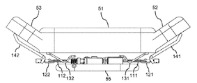
도 1a 및 도 1b는 조정 가능한 시트(10)를 개략적으로 나타낸다. 도 1a 및 도 1b는 시트(10)를 조정하는 다양한 자유도를 나타낸다. 나타낸 예에서, 시트(10)는 차량 시트, 특히 자동차용 운전자 시트 또는 승객 시트인 것으로 가정된다. 그러나, 유사한 구성이 또한 다른 유형의 시트, 예를 들어, 트럭, 항공기 또는 기차와 같은 다른 유형의 차량 또는 좌석 가구에 대한 시트에 사용될 수 있음에 유의한다.1A and 1B schematically show an
나타낸 바와 같이, 시트(10)는 시트 쿠션부(20), 등받이부(30) 및 머리 받침대(50)를 포함한다. 등받이부(30)에는 예를 들어, 와이어 바스켓 또는 가요성 플라스틱 요소로서 구성된 요추 지지부(40)가 제공될 수 있다. 시트(10)는 양방향 화살표에 의해 나타낸 다양한 자유도에 따라 조정 가능한 것으로 가정된다. 나타낸 바와 같이, 이러한 자유도는: HH로 표기되는 수평 방향으로의 머리 받침대(50)의 변위, HV로 표기되는 수직 방향으로의 머리 받침대(50)의 변위, LH로 표기되는 수평 방향으로의 요추 지지부(40)의 변위, LA로 표기되는 요추 지지부(40)의 아칭의 조정, SL로 표기되는 시트 쿠션부(20)의 수평 길이의 조정, 및 LF로 표기되는 시트 쿠션부(20)의 전방 에지에서의 다리 지지부의 틸팅을 포함할 수 있다. 여기서, "수평" 방향은 시트의 정상 설치 위치를 지칭하고, 실질적으로 시트 쿠션부(20)의 평면 내의 방향에 대응한다. 특히, 본원에 설명되는 수평 변위는 전/후 방향을 따른 변위에 대응할 수 있으며, 전방 방향은 시트 쿠션부(20)의 후방 에지 BE로부터의 방향에 대응하고, 여기서 머리 받침대부(30)는 시트 쿠션부(20)의 대향하는 전방 에지 FE에 부착되고, 후방 방향은 전방 에지 FE로부터 후방 에지 BE로의 방향에 대응한다. "수직" 방향은 등받이부(30)를 따르는 방향을 지칭한다. 수직 방향은 통상적으로 수평 방향에 실질적으로 수직이다. 수직 방향은 또한 상/하 방향으로 지칭될 수 있으며, 상방은 시트 쿠션부(20)로부터 머리 받침대(50)를 향한 방향에 대응하며, 하방은 머리 받침대(50)로부터 시트 쿠션부(20)를 향한 방향에 대응한다. 일부 상황에서, 예를 들어, 등받이부(30)가 수면 위치로 후방으로 틸팅되어 있을 때, 수직 또는 상/하 방향은 또한 수평 방향에 수직인 방향으로부터 벗어날 수 있음에 유의한다.As shown, the
도 1a에 나타낸 바와 같이, 시트 쿠션부(20)의 길이의 조정성은 시트 쿠션부(20)에 주요부에 대해 전/후 방향으로 슬라이딩 가능한 시트 쿠션 요소(25)를 시트 쿠션부(20)에 제공함으로써 구현될 수 있다. 상술한 틸팅 가능한 다리 지지부는 슬라이딩 가능한 시트 쿠션 요소(25)의 전방 에지 측 상의 플랩 요소(26)에 의해 제공될 수 있다.As shown in Fig. 1A, the adjustability of the length of the
도 1b는 머리 받침대(50)의 개략적인 평면도를 나타낸다. 도 1b에 추가로 나타낸 바와 같이, 시트(10)의 조정을 위한 추가의 자유도는 BA로 표기된 머리 받침대(50)의 측면 볼스터의 조정에 대응할 수 있다. 특히, 머리 받침대(50)에는 주요부(51), 주요부(51)의 우측 상의 제1 플랩 요소(52) 및 주요부(51)의 좌측 상의 제2 플랩 요소(53)가 제공될 수 있다. 나타낸 바와 같이, 플랩 요소(52, 53)는 머리 받침대(51)의 주요부(51)에 대해 수직 축을 중심으로 틸팅될 수 있다. 따라서, 플랩 요소(52)는 머리 받침대의 조정 가능한 우측 볼스터를 규정하고, 플랩 요소(53)는 머리 받침대(50)의 조정 가능한 좌측 볼스터를 규정한다.1B shows a schematic top view of the
시트(10)의 조정을 위한 상술한 자유도는 조정성의 예의 철저하지 않은 리스트로서 이해되어야 한다는 점에 유의한다. 따라서, 이러한 모든 자유도에 따른 조정이 시트(10)에 의해 지지될 필요는 없거나, 시트(10)는 하나 이상의 다른 자유도에 따른 조정을 또한 지원할 수 있다.Note that the above-mentioned degrees of freedom for adjustment of the
이하에서 추가로 설명되는 예에서, 적어도 2개의 자유도에 따른 시트(10)의 조정은 단일 모터를 사용하여 전동 방식으로 구현되는 것으로 가정된다. 대응하는 조정 기구의 예가 이제 도 2a, 도 2b, 도 2c, 도 3a, 도 3b, 도 3c, 도 4a, 도 4b, 도 4c, 도 5a, 도 5b, 도 6, 도 7a 및 도 7b를 참조하여 추가로 설명될 것이다. 이 예에서, 조정 기구는 머리 받침대(50)의 수평 변위에 의해, 즉, HH로 표기된 자유도에 따라, 머리 받침대(50)의 수직 변위에 의해, 즉, HV로 표기된 자유도에 따라, 그리고 머리 받침대(50)의 측면 볼스터의 틸팅에 의해, 즉, BA로 표기된 자유도에 따라 시트(10)의 전동식 조정을 제공하는 것으로 가정된다. 그러나, 2개 이상의 자유도의 다른 조합에 따른 조정을 위해 조정 기구의 유사한 구성이 또한 사용될 수 있음에 유의해야 한다.In the examples further described below, it is assumed that the adjustment of the
도 2a, 도 2b 및 도 2c는 다른 조정 상태에서의 머리 받침대(50)의 평면도를 나타내며, 조정 기구는 예시의 목적으로 노출된다. 구체적으로, 도 2a는 중립 위치에서의 머리 받침대(50)를 나타내고, 도 2b는 머리 받침대(50)의 주요부가 중립 위치로부터 전방 방향으로 변위된 상태의 머리 받침대(50)를 나타내고, 도 2c는 플랩 요소(52, 53)가 중립 위치로부터 틸팅된 상태의 머리 받침대(50)를 나타낸다. 조정 기구는 주요부(51)와 플랩 요소(52, 53)를 브래킷(55)에 커플링시키며, 이에 의해 머리 받침대(50)가 시트(10)의 등받이부(30)에 부착된다. 조정 기구는 스핀들 구동에 기초하며 전동식 조정을 구동하기 위해 스크류 샤프트(111, 112)(또는 스핀들)를 사용한다. 나타낸 바와 같이, 스크류 샤프트(111, 112)는 조정 기구의 중심부로부터 대향 방향으로 수평으로 연장된다. 제1 너트 요소(121)가 제1 스크류 샤프트(111)와 결합되고, 제2 너트 요소(122)가 제2 스크류 샤프트(112)와 결합된다. 제1 너트 요소(121) 및 제2 너트 요소(122)는 각각의 스크류 샤프트(111, 112)를 따라 이동 가능하지만, 스크류 샤프트(111, 112) 주위의 회전에 대해 락킹된다. 따라서, 스크류 샤프트(111, 112)의 회전은 스크류 샤프트(111, 112)를 따라 각각의 너트 요소(121, 122)의 선형 이동으로 전환된다. 나타낸 예에서, 제1 스크류 샤프트(111) 및 제2 스크류 샤프트(112)는 단일 구동 샤프트의 대향 단부 상에 형성되는 것으로 가정된다. 따라서, 이러한 구동 샤프트의 회전은 제1 스크류 샤프트(111) 및 제2 스크류 샤프트(112)의 대응 회전을 생성하며, 이는 결국 너트 요소(121, 122)의 선형 이동으로 전환된다. 제1 스크류 샤프트(111) 및 제2 스크류 샤프트(112) 중 하나는 왼 나사를 갖지만, 제1 스크류 샤프트(111) 및 제2 스크류 샤프트(112) 중 다른 하나는 오른 나사를 갖는 것으로 가정된다. 따라서, 구동 샤프트가 특정 방향으로 회전되면, 너트 요소(121, 122)의 선형 이동은 반대 방향이 될 것이다.2A, 2B and 2C show plan views of the
추가로 나타낸 바와 같이, 머리 받침대(50)의 주요부(51)는 레버(131, 132)에 의해 브래킷(55)에 커플링된다. 레버(131, 132)는 각각 수직 틸트 축을 중심으로 회전 가능하게 지지된다. 너트 요소(121, 122)의 선형 이동의 제1 범위에서, 너트 요소(121)는 레버(131)와 결합되고, 너트 요소(122)는 레버(132)와 결합된다. 이는 너트 요소(121, 122)의 선형 이동이 레버(131, 132)의 회전으로 전환되고, 이는 결국 도 2b에 나타낸 바와 같이, 머리 받침대(50)의 주요부(51)를 전/후 방향으로 변위시키는 효과를 갖는다.As further shown, the
추가로 나타낸 바와 같이, 머리 받침대(50)의 플랩 요소(52)는 레버(141)에 의해 브래킷(55)에 커플링되고, 머리 받침대의 플랩 요소(53)는 레버(142)에 의해 브래킷(55)에 커플링된다. 레버(141, 142)는 각각 수직 틸트 축을 중심으로 회전 가능하도록 지지된다. 너트 요소(121, 122)의 선형 이동의 제2 범위에서, 너트 요소(121)는 레버(141)와 결합되고, 너트 요소(142)는 레버(142)와 결합된다. 이는 너트 요소(121, 122)의 선형 이동이 레버(141, 142)의 회전으로 전환되고, 이는 결국 도 2c에 나타낸 바와 같이, 머리 받침대(50)의 플랩 요소(52, 53)를 틸팅시키는 효과를 갖는다.As further shown, the
도 2a, 도 2b 및 도 2c에서는 머리 받침대(50)의 주요부(51)의 전/후 방향으로의 변위가 플랩 요소(52, 53)를 이동시키지 않고 발생하는 것으로 나타내어져 있지만, 플랩 요소(52, 53)의 전/후 방향으로의 이동을 주요부(51)의 전/후 방향으로의 이동에 커플링시키는 것이 또한 가능하다는 점에 유의한다. 이는 예를 들어, 도 2a에 짧은 점선에 의해 나타낸 바와 같이, 예를 들어, 덮개 요소 및/또는 공통 커버에 의해 및/또는 주요부(51) 상에 지지부를 제공함으로써 플랩 요소(52, 53)를 주요부(51)에 커플링시킴으로써 달성될 수 있다. 따라서, 따라서, 조정 기구는 또한 전체적으로 머리 받침대(50)의 수평 변위에 대해 사용될 수 있다.2A, 2B, and 2C, displacement of the
도 3a, 도 3b 및 도 3c는 머리 받침대(50)의 주요부(51)의 수평 변위에 의한 머리 받침대(50)의 조정을 추가로 나타낸다. 도 3a, 도 3b 및 도 3c는 너트 요소(121)에 의한 레버(131)의 작동을 추가로 나타낸다. 여기서, 레버(132)는 너트 요소(122)에 의해 대응하는 방식으로 작동될 것임을 이해해야 한다.3A, 3B and 3C further show the adjustment of the
도 3a는 너트 요소(121)와 레버(131)가 중립 위치에 있고 아직 서로 결합되지 않은 상태를 나타낸다. 제1 방향으로의 스크류 샤프트(111)의 회전에 의해, 너트 요소(121)는 도 3b에 나타낸 바와 같이, 결국 레버(131)와 결합할 때까지 레버(131)를 향해 이동될 수 있다. 제1 방향으로의 스크류 샤프트(111)의 추가의 회전에 의해, 너트 요소(121)는 레버(131)에 대해 가압되어, 레버(131)의 회전 및 머리 받침대(50)의 주요부(51)의 전방 변위를 도 3c에 나타낸 바와 같이 최대 변위 위치에 도달할 때까지 발생시킨다. 스크류 샤프트(111)를 반대 방향으로 회전시킬 때, 레버(131)는 점차 중립 위치로 복귀할 수 있게 된다. 이러한 복귀 이동은 예를 들어, 스프링 력에 의해 구동될 수 있다. 예를 들어, 레버(131)는 레버(131)를 중립 위치로부터 회전시킬 때 변형되는 스프링 요소에 커플링될 수 있거나, 레버(131) 자체가 스프링 특성을 나타낼 수 있다.3A shows a state in which the
도 4a, 도 4b 및 도 4c는 머리 받침대(50)의 플랩 요소(52, 53) 틸팅에 의한 머리 받침대의 조정을 나타낸다. 도 4a, 도 4b 및 도 4c는 너트 요소(121)에 의한 레버(141)의 작동을 추가로 나타낸다. 여기서, 레버(142)는 너트 요소(122)에 의해 대응하는 방식으로 작동될 것임을 이해해야 한다.4A, 4B and 4C show the adjustment of the headrest by tilting the
도 4a는 너트 요소(121)와 레버(141)가 중립 위치에 있고 아직 서로 결합되지 않은 상태를 나타낸다. 상술한 제1 방향과 반대인 제2 방향으로의 스크류 샤프트(111)의 회전에 의해, 너트 요소(121)는 도 4b에 나타낸 바와 같이 레버(141)와 결국 결합할 때까지 레버(141)를 향해 이동될 수 있다. 제2 방향으로의 스크류 샤프트(111)의 추가의 회전에 의해, 너트 요소(121)는 레버(141)에 대해 가압되어, 도 4c에 나타낸 바와 같이 최대 틸트 위치에 도달할 때까지 레버(141)의 회전 및 머리 받침대(50)의 플랩 요소(52)의 틸팅을 발생시킨다. 스크류 샤프트(111)를 반대 방향으로 회전시킬 때, 레버(141)는 점차 중립 위치로 복귀할 수 있게 된다. 이러한 복귀 이동은 예를 들어, 스프링 력에 의해 구동될 수 있다. 예를 들어, 레버(141)는 레버(141)를 중립 위치로부터 회전시킬 때 변형되는 스프링 요소에 커플링될 수 있거나, 레버(141) 자체가 스프링 특성을 나타낼 수 있다.4A shows a state in which the
따라서, 도 3b 및 도 3c는 너트 요소(121)의 선형 이동의 상술한 제1 범위의 한계를 규정하고, 도 4b 및 도 4c는 너트 요소(121)의 선형 이동의 상술한 제2 범위의 한계를 규정한다. 여기서, 나타낸 예에서 제1 범위와 제2 범위는 분리되며, 즉, 중첩되지 않는다는 것에 유의한다. 그러나, 제1 범위와 제2 범위가 일부 중첩을 갖는 것이 또한 가능할 수 있을 것이다. 이 경우, 주요부(51)의 변위의 일부는 플랩 요소(52, 53)의 틸팅과 동시에 발생할 것이다.Accordingly, FIGS. 3B and 3C define the above-described first range limit of the linear movement of the
도 5a 및 도 5b는 수직 변위에 의한 머리 받침대(50)의 추가의 조정을 나타낸다. 구체적으로, 도 5a 및 도 5b는 다른 수직 위치에서의 머리 받침대(50)의 후면도를 나타내며, 조정 기구는 예시의 목적으로 노출된다. 도 5a는 머리 받침대(50)의 가장 낮은 위치를 나타내고, 도 5b는 머리 받침대(50)가 가장 낮은 위치로부터 위쪽으로 변위되는 것을 나타낸다.5A and 5B show further adjustment of the
도 5a 및 도 5b에 나타낸 바와 같이, 조정 기구는 수직 방향으로 연장되는 제3 스크류 샤프트(113)를 포함한다. 제3 너트 요소(123)가 제3 스크류 샤프트(113)와 결합하여 브래킷(55)에 연결된다. 제3 스크류 샤프트(113) 및 제3 너트 요소(123)는 브래킷(55)에 대한 머리 받침대(50)의 수직으로 조정 가능한 커플링을 제공한다. 특히, 제3 스크류 샤프트(113)의 회전은 제3 스크류 샤프트(113)의 제3 너트 요소(123)의 선형 이동을 야기할 것이며, 이에 의해 도 5a 및 도 5b에 나타낸 바와 같이 머리 받침대(50)를 수직으로 변위시킨다.5A and 5B, the adjustment mechanism includes a
도 5a 및 도 5b는 나타낸 예에서 제1 스크류 샤프트(111), 제2 스크류 샤프트(112) 및 제3 스크류 샤프트(113)를 구동하기 위해 사용되는 모터(150)를 추가로 나타낸다. 모터(150)는 전기 모터일 수 있고, 시트(10)를 조정하기 위해 전자적으로 제어될 수 있다. 모터(150)는 예를 들어, 전자 정류 방식을 사용하는 브러시리스(brushless) 모터일 수 있다. 브러시리스 모터로서 모터(150)를 구현하는 것은 소음을 감소시키고 및/또는 내구성 및 신뢰성을 향상시키는 데 도움이 될 수 있다. 모터(150)는 양쪽 스크류 샤프트(111, 112)를 구동하기 위해 사용되므로, 복수의 모터의 사용이 필요하지 않기 때문에, 브러시리스 모터를 사용하기 위한 과도한 비용을 피할 수 있다.5A and 5B further show the
모터(150)를 스크류 샤프트(111, 112, 113)에 커플링시키기 위해, 조정 기구에는 추가로 후술하는 바와 같이 기어(155, 180) 및 클러치 기구(160)가 제공된다. 기어(155)는 조정 기구의 컴팩트한 구현을 용이하게 하는 동시에 모터(150)의 회전 속도를 스크류 샤프트(111, 112, 113)의 원하는 회전 속도로 효율적으로 적응시킬 수 있게 하는 2-스테이지 웜(worm) 기어이다. 기어(180)는 제1 및 제2 스크류 샤프트(111, 112)의 수평 축 및 제3 스크류 샤프트(113)의 수직 축을 따른 회전의 전환에 사용되는 웜 기어이다. 클러치 기구(160)는 제1 및 제2 스크류 샤프트(111, 112) 또는 제3 스크류 샤프트(113)와 모터(150)를 선택적으로 결합시킬 수 있게 한다. 클러치 기구(160)에는 클러치 기구(160)의 상태를 전자적으로 제어할 수 있게 하는 액추에이터(170)가 제공된다. 특히, 액추에이터(170)는 모터(150)가 제1 및 제2 스크류 샤프트(111, 112)와 결합되는 제1 상태와, 모터(150)가 제3 스크류 샤프트(113)와 결합되는 제2 상태 사이에서 클러치 기구(160)를 전자적으로 스위칭하는 데 사용될 수 있다. 나타낸 예에서, 액추에이터(170)는 솔레노이드 액추에이터인 것으로 가정된다. 그러나, 다른 유형의 액추에이터도 사용될 수 있다. 예를 들어 추가로 후술하는 바와 같이, SMA 기반 액추에이터가 또한 클러치 기구(160)의 상태 사이에서의 스위칭을 위해 사용될 수 있다.To couple the
클러치 기구(160)를 사용하여 모터(150)를 제3 스크류 샤프트(113)와 결합시키면서 모터(150)를 제1 및 제2 스크류 샤프트(111, 112)로부터 결합 해제시킴으로써, 모터(150)는 제3 스크류 샤프트(113)를 배타적으로 구동시키기 위해 사용될 수 있고, 이에 의해 머리 받침대(50)를 수직으로 변위시키거나 머리 받침대(50)의 플랩 요소(52, 53)를 틸팅시키지 않고 머리 받침대(50)의 수직 위치를 조정할 수 있게 된다. 마찬가지로, 클러치 기구(162)를 사용하여 모터(150)를 제1 및 제2 스크류 샤프트(111, 112)와 결합시키면서 모터(150)를 제3 스크류 샤프트(113)로부터 결합 해제시킴으로써, 모터(150)는 제1 및 제2 스크류 샤프트(111, 112)를 배타적으로 구동시키기 위해 사용될 수 있고, 이에 의해 머리 받침대(50)의 수직 위치를 유지하면서 머리 받침대(50)의 주요부(51)를 수직으로 변위시키고 및/또는 머리 받침대(50)의 플랩 요소(52, 53)를 틸팅시킬 수 있게 된다.By using the
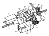
도 6은 조정 기구의 클러치 기구(160)를 추가로 나타낸다. 나타낸 바와 같이, 클러치 기구(160)는 2-스테이지 웜 기어(155)에 의해 구동되는 제1 기어 휠(161)을 포함한다. 상술한 바와 같이, 제1 및 제2 스크류 샤프트(111, 112)는 동일한 구동 샤프트의 상이한 부분으로 형성된다. 제1 기어 휠(161)은 이러한 구동 샤프트와 동심으로 배열되지만, 구동 샤프트를 중심으로 회전 가능하다. 따라서, 제1 기어 휠(161)의 회전이 반드시 구동 샤프트의 회전으로 전환되는 것은 아니다. 제1 기어 휠(161) 옆에, 또한 구동 샤프트의 축과 동심으로, 제1 클러치 휠(163)이 구동 샤프트 상에 배열된다. 제1 클러치 휠(163)은 구동 샤프트와 함께 회전한다. 제1 기어 휠(161) 및 제1 클러치 휠(163)은 대향 축 면을 함께 가져와서 제1 기어 휠(161) 및 제1 클러치 휠(163)을 선택적으로 결합시키기 위해 사용되도록 구성되는 대향 축 면을 갖는다. 추가로 후술하는 바와 같이, 제1 기어 휠(161) 및 제1 클러치 휠(163)에는 각각의 축 면에 축 방향으로 연장되는 톱니가 제공될 수 있고, 제1 기어 휠(161) 및 제1 클러치 휠(163)은 이들 축 방향으로 연장되는 톱니의 인터락킹에 의해 결합될 수 있다. 축 방향 톱니의 결합 및/또는 결합 해제를 용이하게 하기 위해, 축 방향 톱니는 예를 들어, 축 방향에 대해 5° 이하의 각도만큼 기울어진 경사진 메이팅 면을 가질 수 있다. 그러나, 제1 기어 휠(161) 및 제1 클러치 휠(163)의 결합하는 다른 방식, 예를 들어, 표면 마찰에 의한 결합도 사용될 수 있음에 유의한다. 제1 클러치 휠(163)이 제1 기어 휠(161)과 결합되면, 구동 샤프트 및 그에 따른 제1 및 제2 스크류 샤프트(111, 112)도 제1 기어 휠(161)과 함께 회전하며, 즉, 모터(150)에 의해 구동된다. 제1 클러치 휠(163)이 제1 기어 휠(161)로부터 결합 해제되면, 구동 샤프트 및 그에 따른 제1 및 제2 스크류 샤프트(111, 112)도 제1 기어 휠(161)과 함께 회전하지 않으며, 즉, 모터(150)에 의해 구동되지 않는다.6 further shows the
클러치 기구는 제1 및 제2 스크류 샤프트(111, 112)의 구동 샤프트에 평행하게 배열된 추가 구동 샤프트(181) 상에 배열된 제2 기어 휠(164)을 추가로 포함한다. 제2 기어 휠(164)은 제1 기어 휠(161)과 결합된다. 따라서, 모터(150)는 제1 기어 휠(161)을 통해 제2 기어 휠(164)을 구동시킨다. 제2 기어 휠(164)은 추가의 구동 샤프트(181)를 중심으로 회전될 수 있으면서 추가 구동 샤프트(181)와 동심으로 배열된다. 따라서, 제2 기어 휠(164)의 회전이 반드시 추가 구동 샤프트(181)의 회전으로 전환될 필요는 없다. 제2 기어 휠(164) 옆에, 추가 구동 샤프트(181)의 축과 동심으로, 제2 클러치 휠(166)이 추가 구동 샤프트(181) 상에 배열된다. 제2 클러치 휠(166)은 추가 구동 샤프트(181)와 함께 회전한다. 제2 기어 휠(164)과 제2 클러치 휠(166)은 대향하는 축 방향 면을 함께 가져옴으로써 제2 기어 휠(164) 및 제2 클러치 휠(166)을 선택적으로 결합시키기 위해 사용되도록 구성되는 대향하는 축 방향 면을 갖는다. 추가로 후술하는 바와 같이, 또한 제2 기어 휠(164) 및 제2 클러치 휠(163)에는 각각의 축 방향 면 상에 축 방향으로 연장되는 톱니가 제공될 수 있고, 제2 기어 휠(164) 및 제2 클러치 휠(166)은 이들 축 방향으로 연장되는 톱니의 인터락킹에 의해 결합될 수 있다. 축 방향 톱니의 결합 및/또는 결합 해제를 용이하게 하기 위해, 축 방향 톱니는 예를 들어 축 방향에 대해 5° 이하의 각도만큼 기울어진 경사진 메이팅 면을 가질 수 있다. 그러나, 제2 기어 휠(164) 및 제2 클러치 휠(166)과 결합하는 다른 방식, 예를 들어, 표면 마찰에 의한 결합도 사용될 수 있음에 유의한다. 제2 클러치 휠(166)이 제2 기어 휠(164)과 결합되면, 추가 구동 샤프트(181)는 제2 기어 휠(164)과 함께 회전하며, 즉, 모터(150)에 의해 구동된다. 웜 기어(180)를 통해, 추가 구동 샤프트(181)가 제3 스크류 샤프트(113)를 구동시킨다. 제2 클러치 휠(166)이 제2 기어 휠(164)로부터 결합 해제되면, 추가 구동 샤프트(181) 및 그에 따른 제3 스크류 샤프트(113)도 제2 기어 휠(166)과 함께 회전하지 않으며, 즉, 모터(150)에 의해 구동되지 않는다.The clutch mechanism further includes a
액추에이터(170)는 제1 기어 휠(161)과 제1 클러치 휠(163)의 결합 및 제2 기어 휠(164)과 제2 클러치 휠(166)의 결합을 제어하기 위해 사용된다. 이는 제1 및 제2 스크류 샤프트(111, 112)의 구동 샤프트 상의 제1 클러치 휠(163)의 축 방향 시프팅 및 추가 구동 샤프트(181) 상의 제2 클러치 휠(166)의 축 방향 시프팅에 의해 달성된다. 이것이 도 7a 및 도 7b에 추가로 나타내어진다.The
도 7a는 모터(150)가 제1 및 제2 스크류 샤프트(111, 112)와 결합되고 제3 스크류 샤프트(113)로부터 결합 해제되는 제1 상태에서의 클러치 기구(160)를 나타낸다. 알 수 있는 바와 같이, 제1 상태에서 액추에이터(170)의 이펙터 단부(171)는 이동 거리 D만큼 연장된다. 이펙터 단부(171)는 제1 클러치 휠(163)과 제2 클러치 휠(166) 모두에 커플링된다. 결과적으로, 제1 클러치 휠(163)은 제1 기어 휠(161)을 향해 시프트되고, 제2 클러치 휠(166)은 제2 기어 휠(164)로부터 멀리 시프트된다. 따라서, 제1 클러치 휠(163)이 제1 기어 휠(161)과 결합하면서, 제2 클러치 휠(166)은 제2 기어 휠(164)로부터 결합 해제된다. 나타낸 바와 같이, 제1 기어 휠(161)과 제1 클러치 휠(163)의 결합은 제1 기어 휠(161)의 축 방향 톱니(162)와 제1 클러치 휠(163)의 상보적인 축 방향 톱니의 인터락킹에 의해 달성된다. 제1 기어 휠(161)의 축 방향 톱니(162)와 제1 클러치 휠(163)의 상보적인 축 방향 톱니와의 결합 및/또는 결합 해제를 용이하게 하기 위해, 축 방향 톱니(162) 및 상보적인 축 방향 톱니는 예를 들어, 축 방향에 대해 5° 이하의 각도만큼 기울어진 경사진 메이팅 면을 가질 수 있다. 경사진 메이팅 면으로 인해, 축 방향 톱니(162)는 제1 클러치 휠(163)을 향해 테이퍼링되고 제1 클러치 휠(163)의 2개의 이웃하는 상보적인 톱니 사이의 좁아지는 갭에 맞는 외부 형상을 갖는다. 하지만, 제1 기어 휠(161)과 제1 클러치 휠(163)을 결합하는 다른 방식도 사용될 수 있다.7A shows the
도 7b는 모터(150)가 제3 스크류 샤프트(113)와 결합하고 제1 및 제2 스크류 샤프트(111, 112)로부터 결합 해제되는 제2 상태에서의 클러치 기구(160)를 나타낸다. 알 수 있는 바와 같이, 제2 상태에서 액추에이터(170)의 이펙터 단부(171)는 퇴피된다. 결과적으로, 제1 클러치 휠(163)은 제1 기어 휠(161)로부터 멀어지게 시프트되고, 제2 클러치 휠(166)은 제2 기어 휠(164)을 향해 시프트된다. 따라서, 제1 클러치 휠(163)이 제1 기어 휠(161)로부터 결합 해제되면서, 제2 클러치 휠(166)이 제2 기어 휠(164)과 결합한다. 나타낸 바와 같이, 제2 기어 휠(164)과 제2 클러치 휠(166)의 결합은 제2 기어 휠의 축 방향 톱니(165)와 제2 클러치 휠(166)의 상보적인 축 방향 톱니의 인터락킹에 의해 달성된다. 제2 기어 휠(165)의 축 방향 톱니(165)와 제2 클러치 휠(166)의 상보적인 축 방향 톱니의 결합 및/또는 결합 해제를 용이하게 하기 위해, 축 방향 톱니(165) 및 상보적인 축 방향 톱니는 예를 들어, 축 방향에 대해 5° 이하의 각도만큼 기울어진 경사진 메이팅 면을 가질 수 있다. 경사진 메이팅 면으로 인해, 축 방향 톱니(165)는 제2 클러치 휠(166)을 향해 테이퍼링되고 제2 클러치 휠(166)의 2개의 이웃하는 상보적인 톱니 사이의 좁아지는 갭에 맞는 외부 형상을 갖는다. 그러나 제2 기어 휠(164)과 제2 클러치 휠(166)의 결합하는 다른 방식도 사용될 수 있다.7B shows the
알 수 있는 바와 같이, 나타낸 예의 조정 기구는 단일 모터에 의해 상이한 자유도에 따라 시트(10)의 조정을 효율적으로 제어하기 위해, 즉, 머리 받침대(50)의 수평 변위를 제어하기 위해, 특히 전/후 방향으로의 머리 받침대(50)의 주요부(51)의 변위를 조정하기 위해, 플랩 요소(52, 53)를 틸팅시킴으로써 머리 받침대(50)의 측면 볼스터를 조정하기 위해, 그리고 수직 방향으로의 머리 받침대(50)의 변위를 제어하기 위해, 즉, 머리 받침대(50)의 높이 위치를 조정하기 위해 사용될 수 있다. 조정 기구는 머리 받침대(50) 내에 조정 기구를 수용할 수 있게 하는 컴팩트한 방식으로 구현될 수 있다.As can be seen, the adjustment mechanism of the example shown is in order to efficiently control the adjustment of the
상술한 예는 3개의 상이한 자유도에 따른 시트(10)의 조정을 언급했지만, 유사한 조정 기구가 또한 단지 2개의 자유도에 따라 시트(10)를 제어하기 위해, 예를 들어, 머리 받침대(50)의 수평 변위 및 머리 받침대(50)의 수직 변위만을 제어하기 위해 사용될 수 있음에 유의한다. 또한, 머리 받침대(50)의 수평 또는 수직 변위를 제어하는 것에 대한 대안으로서 또는 부가적으로, 조정 기구가 머리 받침대(50)의 틸팅을 제어하기 위해 또한 사용될 수 있다. 또한, 머리 받침대(50)의 조정과 관련된 자유도를 제어하는 상술한 예에 부가하여 또는 대안으로서, 조정 기구는 또한 요추 지지부(40)의 수직 변위 및/또는 요추 지지부(40)의 아칭을 제어함으로써 요추 지지부(40)의 조정과 같은 등받이부(30)의 조정과 관련된 자유도 및/또는 시트 쿠션 요소(25)의 수평 변위를 제어함으로써 시트 쿠션부(25)의 길이를 제어하는 것과 같은 시트 쿠션부(20)와 관련된 자유도 및/또는 플랩 요소(26)의 틸팅을 제어함으로써 다리 지지부의 조정을 제어하기 위해 사용될 수 있다. 조정 기구는 또한 제어되는 자유도에 따라 시트(10)의 등받이부(30) 또는 시트 쿠션부(20) 내에 수용될 수 있다.Although the above-mentioned example mentioned adjustment of the
조정 기구를 수용하기 위한 위치는 또한 제어될 자유도에 따를 수 있다. 예를 들어, 요추 지지부의 제어 또는 등받이부(30)의 측면 볼스터의 조정과 같은 등받이부(30)와 관련된 자유도의 경우, 조정 기구는 시트(10)의 등받이부(30)에 배열될 수 있다. 유사하게, 시트 쿠션 길이의 조정 또는 다리 지지부의 조정과 같은 시트 쿠션부(20)와 관련된 자유도를 제어하는 경우, 조정 기구는 시트(10)의 시트 쿠션부(20)에 배열될 수 있다. 그러나, 일부 시나리오에서, 조정 기구는 또한 다르게 위치될 수 있다. 예를 들어, 머리 받침대(50)와 관련된 자유도를 제어하기 위해, 조정 기구의 일부는 또한 등받이부(30)에 배열될 수 있다. 머리 받침대(50) 및 등받이부(30)와 관련된 자유도를 제어하기 위해, 조정 기구는 또한 머리 받침대(50)에 수용된 구성 요소 및 등받이부(30)에 수용된 구성 요소를 가질 수 있다.The position for receiving the adjustment mechanism can also depend on the degree of freedom to be controlled. In the case of degrees of freedom associated with the
일부 구현에서, 조정 기구는 시트(10)의 조정을 제어하기 위해 3개 초과의 스크류 샤프트를 사용할 수 있다. 이러한 경우에, 각각의 스크류 샤프트는 적어도 하나의 자유도에 따라 시트(10)의 조정을 제어하기 위해 사용될 수 있다. 상술한 바와 같이, 하나의 스크류 샤프트와 결합된 너트 요소의 상이한 선형 모션의 상이한 범위가 동일한 스크류 샤프트로 복수의 자유도를 제어하기 위해 사용될 수 있다. 하나 이상의 클러치 기구가 동일한 모터에 의해 하나 이상의 복수의 스크류 샤프트 및/또는 다른 유형의 구동 샤프트를 선택적으로 제어하기 위해 사용될 수 있다.In some implementations, the adjustment mechanism can use more than three screw shafts to control adjustment of the
도 8은 시트(10)의 조정 기구에 대한 클러치 기구(260)의 추가 예를 나타낸다. 클러치 기구(160)는 상술한 클러치 기구(160)에 대한 대안으로서 또는 부가적으로 사용될 수 있다. 나타낸 바와 같이, 클러치 기구(260)는 단일 모터(250), 예를 들어, 전자적으로 제어되는 전기 모터로 복수의 스크류 샤프트(211, 212, 213, 214, 215)를 선택적으로 구동하기 위해 사용될 수 있다. 모터(250)는 예를 들어, 전자 정류 방식을 사용하는 브러시리스 모터일 수 있다. 브러시리스 모터로서 모터(250)를 구현하는 것은 소음을 감소시키고 및/또는 내구성 및 신뢰성을 향상시키는 데 도움이 될 수 있다. 모터(250)는 모든 스크류 샤프트(211, 212, 213, 214, 215)를 구동시키기 위해 사용되고, 그에 따라 복수의 모터의 사용이 필요하지 않기 때문에, 브러시리스 모터를 사용하기 위한 과도한 비용을 피할 수 있다. 스크류 샤프트(211, 212, 213, 214, 215) 중 적어도 하나에 대해, 스크류 샤프트 중 하나와 결합된 너트 요소의 다른 범위의 선형 모션이 도 2a, 도 2b, 도 2c, 도 3a, 도 3b, 도 3c, 도 4a, 도 4b 및 5c와 관련하여 설명된 바와 같이, 복수의 자유도를 제어하기 위해 사용될 수 있다.8 shows a further example of the
클러치 기구(260)에서, 모터(250)는 2-스테이지 웜 기어(255)를 사용하여 스크류 샤프트(211)의 구동 샤프트 상의 제1 기어 휠(261) 및 제1 클러치 휠(262)을 구동한다. 제2 기어 휠(263)은 제1 클러치 휠(262) 옆에 배열되며, 스크류 샤프트(211)의 구동 샤프트를 중심으로 회전 가능하다. 따라서, 제2 기어 휠(263)의 회전이 스크류 샤프트(211)의 구동 샤프트의 회전으로 반드시 전환되는 것은 아니다. 제1 클러치 휠(262) 및 제2 기어 휠(263)은 대향하는 축 방향 면을 함께 가져옴으로써 제1 클러치 휠(262)과 제2 기어 휠(263)을 선택적으로 결합시키기 위해 사용되도록 구성되는 대향하는 축 방향 면을 갖는다. 나타낸 바와 같이, 이러한 결합은 제1 클러치 휠(262)의 축 방향 톱니와 제2 기어 휠(263)의 상보적인 축 방향 톱니의 인터락킹에 의해 달성될 수 있다. 축 방향 톱니와 상보적인 축 방향 톱니의 결합 및/또는 결합 해제를 용이하게 하기 위해, 제1 클러치 휠(262)의 축 방향 톱니 및 제2 기어 휠(263)의 상보적인 축 방향 톱니는 예를 들어, 축 방향에 대해 5° 이하의 각도만큼 기울어진 경사진 메이팅 면을 가질 수 있다. 경사진 메이팅 면으로 인해, 축 방향 톱니는 제2 기어 휠(263)을 향해 테이퍼링되고 제2 기어 휠(263)의 2개의 이웃하는 상보적인 톱니 사이의 좁아지는 갭에 맞는 외부 형상을 갖는다. 하지만, 대향하는 축 방향 면의 다른 결합 방식도 사용될 수 있다.In the
제2 기어 휠(263) 옆에, 제2 클러치 휠(264)이 스크류 샤프트(211)의 구동 샤프트 상에 배열된다. 제2 클러치 휠(264)은 스크류 샤프트(211)와 함께 회전한다. 제2 기어 휠(263) 및 제2 클러치 휠(264)은 대향하는 축 방향 면을 함께 가져옴으로써 제2 기어 휠(263)과 제2 클러치 휠(264)을 선택적으로 결합시키기 위해 사용되도록 구성된 대향하는 축 방향 면을 갖는다. 나타낸 바와 같이, 이러한 결합은 제2 클러치 휠(264)의 축 방향 톱니와 제2 기어 휠(263)의 상보적인 축 방향 톱니의 인터락킹에 의해 달성될 수 있다. 축 방향 톱니와 상보적인 축 방향 톱니의 결합 및/또는 결합 해제를 용이하게 하기 위해, 제2 클러치 휠(264)의 축 방향 톱니 및 제2 기어 휠(263)의 상보적인 축 방향 톱니는 예를 들어, 축 방향에 대해 5° 이하의 각도만큼 기울어진 경사진 메이팅 면을 가질 수 있다. 경사진 메이팅 면으로 인해, 축 방향 톱니는 제2 기어 휠(263)을 향해 테이퍼링되고 제2 기어 휠(263)의 2개의 이웃하는 상보적인 톱니 사이의 좁아지는 갭에 맞는 외부 형상을 갖는다. 그러나, 대향하는 축 방향 면의 다른 결합 방식도 사용될 수 있다.Next to the
제3 기어 휠(271) 및 제3 클러치 휠(272)이 스크류 샤프트(212)의 구동 샤프트 상에 배열된다. 제3 기어 휠(271)은 제1 기어 휠(261)과 결합하여 구동된다. 제3 클러치 휠(272)은 제3 기어 휠(271)과 함께 회전하여 또한 제1 기어 휠(261)에 의해 구동된다. 제4 기어 휠(273)은 제3 클러치 휠(272) 옆에 배열되며 스크류 샤프트(212)의 구동 샤프트를 중심으로 회전 가능하다. 따라서, 제4 기어 휠(273)의 회전은 스크류 샤프트(212)의 구동 샤프트의 회전으로 반드시 전환되지는 않는다. 제3 클러치 휠(272) 및 제4 기어 휠(273)은 대향하는 축 방향 면을 함께 가져옴으로써 제3 클러치 휠(272)과 제4 기어 휠(273)을 선택적으로 결합시키기 위해 사용되도록 구성되는 대향하는 축 방향 면을 갖는다. 나타낸 바와 같이, 이러한 결합은 제3 클러치 휠(272)의 축 방향 톱니와 제4 기어 휠(273)의 상보적인 축 방향 톱니의 인터락킹에 의해 달성될 수 있다. 축 방향 톱니와 상보적인 축 방향 톱니의 결합 및/또는 결합 해제를 용이하게 하기 위해, 제3 클러치 휠(272)의 축 방향 톱니 및 제4 기어 휠(273)의 상보적인 축 방향 톱니는 예를 들어, 축 방향에 대해 5° 이하의 각도만큼 기울어진 경사진 메이팅 면을 가질 수 있다. 경사진 메이팅 면으로 인해, 축 방향 톱니는 제4 기어 휠(273)을 향해 테이퍼링되고 제4 기어 휠(273)의 2개의 이웃하는 상보적인 톱니 사이의 좁아지는 갭에 맞는 외부 형상을 갖는다. 그러나, 대향하는 축 방향 면을 결합하는 다른 방식도 사용될 수 있다.The
제4 기어 휠(273) 옆에, 제4 클러치 휠(274)이 스크류 샤프트(212)의 구동 샤프트 상에 배열된다. 제4 클러치 휠(274)은 스크류 샤프트(212)와 함께 회전한다. 제4 기어 휠(273) 및 제4 클러치 휠(274)은 대향하는 축 방향 면을 함께 가져옴으로써 제4 기어 휠(273)과 제4 클러치 휠(274)을 선택적으로 결합시키기 위해 사용되도록 구성되는 대향하는 축 방향 면을 갖는다. 나타낸 바와 같이, 이러한 결합은 제4 클러치 휠(274)의 축 방향 톱니와 제4 기어 휠(273)의 상보적인 축 방향 톱니의 인터락킹에 의해 달성될 수 있다. 축 방향 톱니와 상보적인 축 방향 톱니의 결합 및/또는 결합 해제를 용이하게 하기 위해, 제4 클러치 휠(274)의 축 방향 톱니와 제4 기어 휠(273)의 상보적인 축 방향 톱니는 예를 들어, 축 방향에 대해 5° 이하의 각도만큼 기울어진 경사진 메이팅 면을 가질 수 있다. 경사진 메이팅 면으로 인해, 축 방향 톱니는 제4 기어 휠(273)을 향해 테이퍼링되고 제4 기어 휠(273)의 2개의 이웃하는 상보적인 톱니 사이의 좁아지는 갭에 맞는 외부 형상을 갖는다. 그러나, 대향하는 축 방향 면을 결합하는 다른 방식도 사용될 수 있다.Next to the
제5 기어 휠(275)은 스크류 샤프트(213)의 구동 샤프트 상에 배열된다. 제5 기어 휠(275)은 제4 기어 휠(273)과 결합하여 구동된다. 제5 기어 휠(275)은 스크류 샤프트(213)의 구동 샤프트를 중심으로 회전 가능하다. 따라서, 제5 기어 휠(275)의 회전이 반드시 스크류 샤프트(213)의 회전으로 전환되지는 않는다. 제5 기어 휠(275) 옆에, 제5 클러치 휠(276)이 스크류 샤프트(213)의 구동 샤프트 상에 배열된다. 제5 클러치 휠(276)은 스크류 샤프트(213)와 함께 회전한다. 제5 기어 휠(275) 및 제5 클러치 휠(276)은 대향하는 축 방향 면을 함께 가져옴으로써 제5 기어 휠(275)과 제5 클러치 휠(276)을 선택적으로 결합시키기 위해 사용되도록 구성되는 대향하는 축 방향 면을 갖는다. 나타낸 바와 같이, 이러한 결합은 제5 클러치 휠(276)의 축 방향 톱니와 제5 기어 휠(275)의 상보적인 축 방향 톱니의 인터락킹에 의해 달성될 수 있다. 축 방향 톱니와 상보적인 축 방향 톱니의 결합 및/또는 결합 해제를 용이하게 하기 위해, 제5 클러치 휠(276)의 축 방향 톱니 및 제5 기어 휠(275)의 상보적인 축 방향 톱니는 예를 들어, 축 방향에 대해 5° 이하의 각도만큼 기울어진 경사진 메이팅 면을 가질 수 있다. 경사진 메이팅 면으로 인해, 축 방향 톱니는 제5 기어 휠(275)을 향해 테이퍼링되고 제5 기어 휠(275)의 2개의 이웃하는 상보적인 톱니 사이의 좁아지는 갭에 맞는 외부 형상을 갖는다. 그러나, 대향하는 축 방향 면을 결합하는 다른 방식도 사용될 수 있다.The
제6 기어 휠(281)은 스크류 샤프트(214)의 구동 샤프트 상에 배열된다. 제6 기어 휠(281)은 제2 기어 휠(263)과 결합하여 구동된다. 제6 기어 휠(281)은 스크류 샤프트(214)의 구동 샤프트를 중심으로 회전 가능하다. 따라서, 제6 기어 휠(281)의 회전이 반드시 스크류 샤프트(214)의 회전으로 전환되지는 않는다. 제7 기어 휠(282)이 제6 기어 휠(281) 옆에 배열되며, 스크류 샤프트(214)의 구동 샤프트를 중심으로 회전 가능하다. 따라서, 제7 기어 휠(282)의 회전이 반드시 스크류 샤프트(214)의 회전으로 전환되지는 않는다. 제6 기어 휠(281) 및 제7 기어 휠(282)은 대향하는 축 방향 면을 함께 가져옴으로써 제6 기어 휠(281)과 제7 기어 휠(282)을 선택적으로 결합시키기 위해 사용되도록 구성되는 대향하는 축 방향 면을 갖는다. 나타낸 바와 같이, 이러한 결합은 제6 기어 휠(281)의 축 방향 톱니와 제7 기어 휠(282)의 상보적인 축 방향 톱니의 인터락킹에 의해 달성될 수 있다. 축 방향 톱니와 상보적인 축 방향 톱니의 결합 및/또는 결합 해제를 용이하게 하기 위하여, 제6 기어 휠(281)의 축 방향 톱니 및 제7 기어 휠(282)의 상보적인 축 방향 톱니는 예를 들어, 축 방향에 대해 5° 이하의 각도만큼 기울어진 경사진 메이팅 면을 가질 수 있다. 경사진 메이팅 면으로 인해, 축 방향 톱니는 제7 기어 휠(282)을 향해 테이퍼링되고 제7 기어 휠(282)의 2개의 이웃하는 상보적인 톱니 사이의 좁아지는 갭에 맞는 외부 형상을 갖는다. 그러나, 대향하는 축 방향 면을 결합하는 다른 방식도 사용될 수 있다.The
제7 기어 휠(282) 옆에, 제6 클러치 휠(283)이 스크류 샤프트(214)의 구동 샤프트 상에 배열된다. 제6 클러치 휠(283)은 스크류 샤프트(214)와 함께 회전한다. 제7 기어 휠(282) 및 제6 클러치 휠(283)은 대향하는 축 방향 면을 함께 가져옴으로써 제7 기어 휠(282)과 제6 클러치 휠(283)을 선택적으로 결합시키기 위해 사용되도록 구성되는 대향하는 축 방향 면을 갖는다. 나타낸 바와 같이, 이러한 결합은 제6 클러치 휠(283)의 축 방향 톱니와 제7 기어 휠(282)의 상보적인 축 방향 톱니의 인터락킹에 의해 달성될 수 있다. 축 방향 톱니와 상보적인 축 방향 톱니의 결합 및/또는 결합 해제를 용이하게 하기 위해, 제6 클러치 휠(283)의 축 방향 톱니 및 제7 기어 휠(282)의 상보적인 축 방향 톱니는 예를 들어, 축 방향에 대해 5° 이하의 각도만큼 기울어진 경사진 메이팅 면을 가질 수 있다. 경사진 메이팅 면으로 인해, 축 방향 톱니는 제7 기어 휠(282)을 향해 테이퍼링되고 제7 기어 휠(282)의 2개의 이웃하는 상보적인 톱니 사이의 좁아지는 갭에 맞는 외부 형상을 갖는다. 그러나, 대향하는 축 방향 면을 결합하는 다른 방식도 사용될 수 있다.Next to the
제8 기어 휠(284)은 스크류 샤프트(215)의 구동 샤프트 상에 배열되어 있다. 제8 기어 휠(284)은 제7 기어 휠(282)과 결합되어 구동된다. 제8 기어 휠(284)은 스크류 샤프트(215)의 구동 샤프트를 중심으로 회전 가능하다. 따라서, 제8 기어 휠(284)의 회전이 반드시 스크류 샤프트(215)의 회전으로 전환되지는 않는다. 제8 기어 휠(284) 옆에, 제7 클러치 휠(285)이 스크류 샤프트(215)의 구동 샤프트 상에 배열된다. 제7 클러치 휠(285)은 스크류 샤프트(215)와 함께 회전한다. 제8 기어 휠(284) 및 제7 클러치 휠(285)은 대향하는 축 방향 면을 함께 가져옴으로써 제8 기어 휠(284)과 제7 클러치 휠(285)을 선택적으로 결합하기 위해 사용되도록 구성되는 대향하는 축 방향 면을 갖는다. 나타낸 바와 같이, 이러한 결합은 제7 클러치 휠(285)의 축 방향 톱니와 제8 기어 휠(284)의 상보적인 축 방향 톱니의 인터락킹에 의해 달성될 수 있다. 축 방향 톱니와 상보적인 축 방향 톱니의 결합 및/또는 결합 해제를 용이하게 하기 위해, 제7 클러치 휠(285)의 축 방향 톱니 및 제8 기어 휠(284)의 상보적인 축 방향 톱니는 예를 들어, 축 방향에 대해 5° 이하의 각도만큼 기울어진 경사진 메이팅 면을 가질 수 있다. 경사진 메이팅 면으로 인해, 축 방향 톱니는 제8 기어 휠(284)을 향해 테이퍼링되고 제8 기어 휠(284)의 2개의 이웃하는 상보적인 톱니 사이의 좁아지는 갭에 맞는 외부 형상을 갖는다. 그러나, 대향하는 축 방향 면을 결합하는 다른 방식도 사용될 수 있다.The
클러치 기구(260)는 상술한 클러치 휠 또는 기어 휠이 서로 결합했는지에 따라 다양한 상이한 상태로 될 수 있다. 스크류 샤프트(211)는 제1 클러치 휠(262)이 제2 기어 휠(263)과 결합되고 제2 클러치 휠(264)이 제2 기어 휠(263)과 결합되면 모터(250)에 의해 구동된다. 스크류 샤프트(212)는 제3 클러치 휠(272)이 제4 기어 휠(273)과 결합되고 제4 클러치 휠(274)이 제4 기어 휠(273)과 결합되면 모터(250)에 의해 구동된다. 스크류 샤프트(213)는 제5 클러치 휠(276)이 제5 기어 휠(275)과 결합되고 제4 기어 휠(273) 제3 클러치 휠(272)과 결합되면 모터(250)에 의해 구동된다. 스크류 샤프트(214)는 제6 클러치 휠(283)이 제7 기어 휠(282)과 결합되고 제7 기어 휠(282)이 제6 기어 휠(281)과 결합되고 제2 기어 휠(263)이 제1 클러치 휠(262)과 결합되면 모터(250)에 의해 구동된다. 스크류 샤프트(215)는 제7 클러치 휠(285)이 제8 기어 휠(284)과 결합되고 제7 기어 휠(282)이 제6 기어 휠(281)과 결합되고 제2 기어 휠(263)이 제1 클러치 휠(262)과 결합되면 모터(250)에 의해 구동된다.The
또한, 각각의 스크류 샤프트(211, 212, 213, 214, 215)는 모터(250)로부터 결합 해제될 수 있다: 제2 기어 휠(263)로부터 제2 클러치 휠(264)을 결합 해제시킴으로써, 스크류 샤프트(211)는 모터(250)로부터 결합 해제될 수 있으며, 동시에 임의의 다른 스크류 샤프트(212, 213, 214, 215)가 모터(250)와 결합될 수 있게 한다. 제4 기어 휠(273)로부터 제4 클러치 휠(274)을 결합 해제시킴으로써, 스크류 샤프트(212)는 모터(250)로부터 결합 해제될 수 있으며, 동시에 임의의 다른 스크류 샤프트(211, 213, 214, 215)가 모터(250)와 결합될 수 있게 한다. 제5 기어 휠(275)로부터 제5 클러치 휠(276)을 결합 해제시킴으로써, 스크류 샤프트(213)는 모터(250)로부터 결합 해제될 수 있으며, 동시에 임의의 다른 스크류 샤프트(211, 212, 214, 215)가 모터(250)와 결합될 수 있게 한다. 제7 기어 휠(282)로부터 제6 클러치 휠(283)을 결합 해제시킴으로써, 스크류 샤프트(214)는 모터(250)로부터 결합 해제될 수 있으며, 동시에 임의의 다른 스크류 샤프트(211, 212, 213, 215)가 모터(250)와 결합될 수 있게 한다. 제8 기어 휠(284)로부터 제7 클러치 휠(285)을 결합 해제시킴으로써, 스크류 샤프트(215)는 모터(250)로부터 결합 해제될 수 있으며, 동시에 임의의 다른 스크류 샤프트(211, 212, 213, 214)가 모터(250)와 결합될 수 있게 한다.Further, each of the
따라서, 각각의 스크류 샤프트(211, 212, 213, 214, 215)에 각각의 스크류 샤프트(211, 212, 213, 214, 215)의 구동 샤프트를 중심으로 회전 가능한 적어도 하나의 기어 휠 및 스크류 샤프트와 함께 회전하고 각각의 기어 휠과 선택적으로 결합될 수 있는 클러치 휠을 제공함으로써, 클러치 기구(260)는 다양한 상태를 유연하게 지원할 수 있다. 클러치 기구(260)로부터 추가로 알 수 있는 바와 같이, 하나의 구동 샤프트 상의 기어 휠은 다른 구동 샤프트를 구동하기 위해 사용될 수 있고 동시에 클러치 휠 또는 다른 기어 휠과의 선택적인 결합을 위해 사용될 수 있다. 이것은 클러치 기구(260)의 컴팩트하고 효율적인 구현을 가능하게 한다.Accordingly, each
클러치 기구(260)에서, 상술한 바와 같이 복수의 액추에이터가 클러치 휠 및 기어 휠을 선택적으로 결합시키기 위해 사용될 수 있다. 이들 액추에이터는 상술한 액추에이터(170)에 대해 설명된 것과 유사한 솔레노이드 액추에이터로서 구현될 수 있다. 그러나, SMA 기반 액추에이터와 같은 다른 유형의 액추에이터도 사용될 수 있다. 클러치 기구(260)는 또한 솔레노이드 기반 액추에이터와 SMA 기반 액추에이터의 조합과 같은 2개 이상의 상이한 유형의 액추에이터의 조합을 사용할 수 있다. 또한, 상술한 액추에이터(170)에 대해 설명된 바와 같이, 한 쌍 초과의 휠을 결합시키기 위해 하나의 액추에이터를 또한 사용할 수 있다.In the
도 9는 예를 들어, 상술한 클러치 기구(160 또는 260)에 부가적으로 또는 대안으로서 상술한 바와 같은 조정 기구에 사용될 수 있는 또 다른 추가의 클러치 기구(360)를 나타낸다. 나타낸 바와 같이, 클러치 기구(260)는 단일 모터(350), 예를 들어, 전자적으로 제어되는 전기 모터로 복수의 스크류 샤프트(311, 312)를 선택적으로 구동시키기 위해 사용될 수 있다. 모터(350)는 예를 들어, 전자 정류 방식을 사용하는 예를 들어, 브러시리스 모터일 수 있다. 브러시리스 모터로서 모터(350)를 구현하는 것은 소음을 감소시키고 및/또는 내구성 및 신뢰성을 향상시키는 데 도움이 될 수 있다. 모터(350)는 스크류 샤프트(311, 312) 모두를 구동시키기 위해 사용되고 그에 따라 복수의 모터의 사용이 필요하지 않기 때문에, 브러시리스 모터를 사용하기 위한 과도한 비용을 피할 수 있다. 스크류 샤프트(311, 312) 중 적어도 하나에 대해, 스크류 샤프트 중 하나와 결합된 너트 요소의 상이한 범위의 선형 모션이 도 2a, 도 2b, 도 2c, 도 3a, 도 3b, 도 3c, 도 4a, 도 4b 및 도 5c와 관련하여 설명된 바와 같이 복수의 자유도를 제어하기 위해 사용될 수 있다.9 shows another additional
클러치 기구(360)에서, 모터(350)는 2-스테이지 웜 기어(355)를 사용하여 스크류 샤프트(311)를 구동시킨다. 스크류 샤프트(311)와 함께 회전하는 제1 기어 휠(361)은 제2 기어 휠(362)을 구동시키는 데 사용된다. 제2 기어 휠(362)은 스크류 샤프트(312)의 구동 샤프트 상에 배열되어, 스크류 샤프트(312)의 구동 샤프트 중심으로 회전 가능하다. 따라서, 제2 기어 휠(362)의 회전이 반드시 스크류 샤프트(312)의 회전으로 전환되지는 않는다. 제2 기어 휠(362) 옆에, 클러치 휠(363)이 스크류 샤프트(312)의 구동 샤프트 상에 배열된다. 클러치 휠(363)은 스크류 샤프트(312)와 함께 회전한다. 제2 기어 휠(362) 및 클러치 휠(363)은 대향하는 축 방향 면을 함께 가져옴으로써 클러치 휠(363)을 제2 기어 휠(362)과 선택적으로 결합하기 위해 사용되도록 구성되는 대향하는 축 방향 면을 갖는다. 나타낸 바와 같이, 이러한 결합은 클러치 휠(363)의 축 방향 톱니와 제2 기어 휠(362)의 상보적인 축 방향 톱니의 인터락킹에 의해 달성될 수 있다. 축 방향 톱니와 상보적인 축 방향 톱니의 결합 및/또는 결합 해제를 용이하게 하기 위해, 클러치 휠(363)의 축 방향 톱니 및 제2 기어 휠(362)의 상보적인 축 방향 톱니는 예를 들어, 축 방향에 대해 5° 이하의 각도만큼 기울어진 경사진 메이팅 면을 가질 수 있다. 경사진 메이팅 면으로 인해, 축 방향 톱니는 제2 기어 휠(362)을 향해 테이퍼링되고 제2 기어 휠(362)의 2개의 이웃하는 상보적인 톱니 사이의 좁아지는 갭에 맞는 외부 형상을 갖는다. 그러나, 대향하는 축 방향 면을 결합하는 다른 방식도 사용될 수 있다.In
클러치 기구(360)에서, 제2 기어 휠(362)과 클러치 휠(363)의 결합은 SMA 기반 액추에이터(370)에 의해 제어된다. 나타낸 바와 같이, SMA 기반 액추에이터(370)는 SMA 와이어(371) 및 전자적으로 제어되는 히터(372)를 포함한다. 히터(372)에 의한 SMA 와이어(371)의 가열에 응답하여, SMA 와이어(371)는 길이를 변화시킨다. 예를 들어, SMA 와이어(371)는 히터(372)에 의한 가열에 응답하여 짧아질 수 있다. SMA 와이어(371)의 단축은 제2 기어 휠(362)을 축 방향으로 클러치 휠(363)을 향해 가압하는 레버(373)를 작동시키며, 이에 의해 클러치 휠(363)을 제2 기어 휠(362)과 결합시킨다. SMA 와이어(371)의 냉각에 응답하여, SMA 와이어(371)의 길이가 증가하며, 이에 의해 제2 기어 휠(362)을 클러치 휠(363)로부터 멀어지게 이동시켜, 클러치 휠(363)을 제2 기어 휠(362)로부터 결합 해제시킨다. 나타낸 예에서, 레버(373)는 서로 유연하게 연결되는 2개의 부분으로 형성된다. 이는, 예를 들어, 레버(373)가 제2 기어 휠(362)의 축 방향 톱니와 클러치 휠(363)의 상보적인 축 방향 톱니가 잘못 정렬되어 클러치 휠(363)을 향한 제2 기어 휠(362)의 이동을 손상시키면서 레버(373)가 제2 기어 휠(362)을 클러치 휠(363)을 향해 가압하는 경우에 과도한 응력을 피할 수 있게 한다.In the
클러치 기구(360)에서, 클러치 휠(363)이 제2 기어 휠(362)과 결합되면 양쪽 스크류 샤프트(311, 312)는 모터(350)에 의해 구동된다. 클러치 휠(363)이 제2 기어 휠(362)로부터 결합 해제되면, 스크류 샤프트(311)만이 모터(350)에 의해 구동된다. 이것은 예를 들어, 시트(10)의 요추 지지부(40)의 수직 위치 및 시트의 요추 지지부(40)의 아칭을 모두 제어하는 데 유용할 수 있다: 양쪽 스크류 샤프트(311 및 312)를 구동하는 것이 요추 지지부(40)의 수직 위치의 조정을 위해 사용될 수 있지만, 스크류 샤프트(311 및 312) 중 하나만을 구동하는 것이 아칭의 조정을 위해 사용될 수도 있다. 이러한 목적을 위해, 스크류 샤프트(311 및 312) 상의 너트 요소가 요추 지지부(40) 상의 상이한 결합 지점에 커플링될 수 있어, 서로에 대한 이들 결합 지점의 상대 이동이 요추 지지부(40)의 파킹(parking)을 야기한다. 너트 요소 중 적어도 하나의 상이한 이동 범위가 시트(10)의 조정을 위한 하나 이상의 추가의 자유도를 제어하기 위해 사용될 수 있다.In the
예시적인 실시예가 차량 시트의 상황에서 설명되었지만, 본 발명의 실시예에 따른 조정 기구 및 시트는 이러한 특정 어플리케이션에 한정되지 않는다. 오히려, 상술한 바와 같은 조정 기구는 광범위하게 다양한 시트에 채용될 수 있다. 또한, 나타낸 조정 기구는 다양한 방식으로 수정될 수 있음에 유의한다. 예를 들어, 조정 기구는 다양한 개수의 스크류 샤프트를 포함할 수 있으며, 시트의 다양한 부분 내에 수용될 수 있다. 또한, 하나 이상의 스크류 샤프트가 다른 종류의 샤프트, 예를 들어 비틀림 샤프트로 대체될 수 있거나, 다른 추가적인 유형의 샤프트가 상술한 스크류 샤프트를 보충하고 동일한 모터에 의해 구동되도록 사용될 수 있다. 또한, 하나 이상의 스크류 샤프트 또는 다른 샤프트는 또한 가요성일 수 있거나 가요성 부분을 포함할 수 있다. 따라서, 상술한 클러치 기구가 스크류 샤프트를 구동시키기 위해 사용될 수 있지만, 상술한 바와 같이 스크류 샤프트에 부가적으로 또는 대안으로서 다양한 다른 유형의 구동 샤프트를 구동시키기 위해 사용될 수도 있다. 일부 경우에, 이러한 스크류 샤프트 또는 구동 샤프트는 또한 시트의 한 부분으로부터 시트의 다른 부분으로, 예를 들어, 등받이부로부터 머리 받침대로 또는 그 반대로 연장될 수 있다. 또한, 예를 들어, 시트(10)의 등받이부(30)에서 조정 기구의 일부 구성 요소를 수용하고 시트(10)의 머리 받침대(50) 및/또는 시트 쿠션부(20)에서 조정 기구의 다른 구성 요소를 수용함으로써, 시트(10)의 복수의 부분에 걸쳐 분산되어 있는 조정 기구를 사용하는 것이 또한 가능하다. 또한, 상술한 바와 같은 조정 기구는 자유도의 다양한 조합에 대한 시트의 조정을 위해 사용될 수 있다. 예를 들어, 측면 볼스터의 틸팅에 대해 상술한 바와 같은 유사한 원리를 사용하여, 예를 들어, 도 1a에서 HT로 표기된 바와 같이 머리 받침대의 틸팅은 동일한 스크류 샤프트 상의 너트 요소의 상이한 선형 이동 범위를 사용함으로써 구현될 수 있다. 머리 받침대(50)의 전방 틸팅은 예를 들어, 머리 받침대(50)가 최대 상방 위치에 도달했을 때 개시될 수 있다.Although the exemplary embodiment has been described in the context of a vehicle seat, the adjustment mechanism and seat according to the embodiment of the present invention are not limited to this specific application. Rather, the adjustment mechanism as described above can be employed in a wide variety of seats. It is also noted that the indicated adjustment mechanism can be modified in various ways. For example, the adjustment mechanism can include a variable number of screw shafts and can be accommodated within various portions of the seat. Also, one or more screw shafts can be replaced with other types of shafts, for example torsional shafts, or other additional types of shafts can be used to supplement the screw shafts described above and to be driven by the same motor. In addition, one or more screw shafts or other shafts may also be flexible or include flexible parts. Thus, while the clutch mechanism described above can be used to drive a screw shaft, it can also be used to drive a variety of other types of drive shafts in addition to or as an alternative to the screw shaft as described above. In some cases, such a screw shaft or drive shaft may also extend from one part of the seat to another part of the seat, for example from the backrest to the headrest or vice versa. In addition, for example, some components of the adjustment mechanism are received in the
Claims (15)
복수의 스크류 샤프트(111, 112; 211, 212, 213, 214, 215; 311, 312);
상기 스크류 샤프트들(111, 112; 211, 212, 213, 214, 215; 311, 312)을 구동하기 위한 모터(150; 250; 350); 및
상기 모터(150; 250; 350)를 하나 이상의 상기 스크류 샤프트(111, 112; 211, 212, 213, 214, 215; 311, 312)와 선택적으로 결합시키기 위한 클러치 기구(160; 260; 360)를 포함하고;
이에 의해, 상기 모터(150; 250; 350)에 의해 야기된 하나 이상의 상기 스크류 샤프트들(111, 112; 211, 212, 213, 214, 215; 311, 312)의 회전은 제1 자유도에 따라 상기 시트(10)의 조정으로 전환되고, 상기 모터(150; 250; 350)에 의해 야기된 하나 이상의 다른 상기 스크류 샤프트(111, 112; 211, 212, 213, 214, 215; 311, 312)의 회전은 제2 자유도에 따라 상기 시트(10)의 조정으로 전환되는, 조정 기구.As an adjustment mechanism for the seat 10, the adjustment mechanism 10 comprises:
A plurality of screw shafts 111, 112; 211, 212, 213, 214, 215; 311, 312;
A motor (150; 250; 350) for driving the screw shafts 111, 112; 211, 212, 213, 214, 215; 311, 312; And
A clutch mechanism (160; 260; 360) for selectively engaging the motor (150; 250; 350) with one or more of the screw shafts (111, 112; 211, 212, 213, 214, 215; 311, 312) Contains;
Thereby, the rotation of the one or more of the screw shafts 111, 112; 211, 212, 213, 214, 215; 311, 312 caused by the motor 150; 250; 350 is determined according to the first degree of freedom. Rotation of one or more other said screw shafts 111, 112; 211, 212, 213, 214, 215; 311, 312 caused by the motor 150; 250; 350, converted to the adjustment of the seat 10 Is an adjustment mechanism, which is switched to the adjustment of the seat 10 according to the second degree of freedom.
상기 스크류 샤프트들(111, 112; 211, 212, 213, 214, 215; 311, 312) 중 적어도 하나의 구동 샤프트에서, 상기 클러치 기구(160, 260, 360)는 상기 구동 샤프트에 대해 회전 가능한 제1 휠(161, 164; 263, 273, 275, 281, 282, 284; 362) 및 제1 휠(161, 164; 263, 273, 275, 281, 282, 284; 362)과 선택적으로 결합될 수 있는 제2 휠(163, 166; 262, 264, 272, 274, 276, 282, 283, 285; 363)을 포함하는, 조정 기구.According to claim 1,
In at least one drive shaft of the screw shafts 111, 112; 211, 212, 213, 214, 215; 311, 312, the clutch mechanism 160, 260, 360 is rotatable relative to the drive shaft Can be selectively combined with one wheel 161, 164; 263, 273, 275, 281, 282, 284; 362 and a first wheel 161, 164; 263, 273, 275, 281, 282, 284; 362 Adjustment mechanism comprising a second wheel (163, 166; 262, 264, 272, 274, 276, 282, 283, 285; 363).
제1 휠(161, 164; 263, 273, 275, 281, 282, 284) 및 제2 휠(163, 166; 262, 264, 272, 274, 276, 282, 283, 285) 중 적어도 하나는 상기 스크류 샤프트들(111, 112; 211, 212, 213, 214, 215) 중 다른 하나의 구동 샤프트 상의 기어 휠(161, 164; 263, 273, 275, 281, 282, 284)과 결합된 기어 휠인, 조정 기구.According to claim 1,
At least one of the first wheel (161, 164; 263, 273, 275, 281, 282, 284) and the second wheel (163, 166; 262, 264, 272, 274, 276, 282, 283, 285) A gear wheel combined with a gear wheel 161, 164; 263, 273, 275, 281, 282, 284 on a drive shaft of the other of the screw shafts 111, 112; 211, 212, 213, 214, 215, Adjustment mechanism.
상기 제1 자유도 및 상기 제2 자유도는 상기 시트(10)의 머리 받침대(50)의 수평 방향으로 변위, 상기 시트(10)의 상기 머리 받침대(50)의 틸팅(tilting), 상기 시트(10)의 상기 머리 받침대(50)의 수직 변위, 상기 시트(10)의 적어도 하나의 플랩(flap) 요소(26, 52, 53)의 틸팅, 상기 시트(10)의 요추 지지부(40)의 수직 변위, 상기 시트(10)의 상기 요추 지지부(40)의 아칭(arching)의 조정 및 상기 시트(10)의 시트 쿠션부(20)의 길이의 조정을 포함하는 그룹으로부터의 2개의 다른 자유도에 대응하는, 조정 기구.The method according to any one of claims 1 to 3,
The first degree of freedom and the second degree of freedom are displaced in the horizontal direction of the headrest 50 of the seat 10, tilting the headrest 50 of the seat 10, and the seat 10 ) Vertical displacement of the head rest 50, tilting of at least one flap element 26, 52, 53 of the seat 10, vertical displacement of the lumbar support 40 of the seat 10 , Corresponding to two different degrees of freedom from the group comprising adjustment of the arching of the lumbar support 40 of the seat 10 and adjustment of the length of the seat cushion 20 of the seat 10 , Adjustment mechanism.
상기 제1 자유도는 상기 시트(10)의 머리 받침대(50)의 수평 방향으로의 변위 또는 상기 머리 받침대(50)의 틸팅을 포함하고, 상기 제2 자유도는 상기 시트(10)의 상기 머리 받침대(50)의 수직 방향으로의 변위에 대응하는, 조정 기구.The method according to any one of claims 1 to 4,
The first degree of freedom includes displacement of the headrest 50 in the horizontal direction of the seat 10 or tilting of the headrest 50, and the second degree of freedom includes the headrest of the seat 10 ( The adjustment mechanism corresponding to the displacement in the vertical direction of 50).
상기 복수의 스크류 샤프트(111, 112, 113)는 적어도 하나의 제1 스크류 샤프트(111, 112) 및 적어도 하나의 제2 스크류 샤프트(113)를 포함하고;
상기 조정 기구는 상기 적어도 하나의 제1 스크류 샤프트(111, 112)와 결합된 적어도 하나의 너트(nut) 요소(121, 122)를 포함하고;
이에 의해, 상기 모터(150)에 의해 야기된 상기 적어도 하나의 제1 스크류 샤프트(111, 112)의 회전은 상기 적어도 하나의 너트 요소(121, 122)의 선형 모션으로 전환되고,
이에 의해, 상기 적어도 하나의 너트 요소(121, 122)의 상기 선형 모션의 제1 범위에서, 상기 선형 모션은 상기 제1 자유도 및 상기 제2 자유도 중 하나에 따라 상기 시트(10)의 조정으로 전환되고, 상기 적어도 하나의 너트 요소(121, 122)의 상기 선형 모션의 제2 범위에서, 상기 선형 모션은 제3 자유도에 따라 상기 시트(10)의 조정으로 전환되는, 조정 기구.The method according to any one of claims 1 to 5,
The plurality of screw shafts (111, 112, 113) includes at least one first screw shaft (111, 112) and at least one second screw shaft (113);
The adjustment mechanism comprises at least one nut element (121, 122) coupled with the at least one first screw shaft (111, 112);
Thereby, the rotation of the at least one first screw shaft 111, 112 caused by the motor 150 is converted into a linear motion of the at least one nut element 121, 122,
Thereby, in the first range of the linear motion of the at least one nut element (121, 122), the linear motion is adjusted of the seat (10) according to one of the first and second degrees of freedom. And in the second range of the linear motion of the at least one nut element (121, 122), the linear motion is switched to the adjustment of the seat (10) according to a third degree of freedom.
상기 머리 받침대(50)는 상기 머리 받침대(50)의 주요부(51)에 대해 피벗팅(pivoting) 가능한 적어도 하나의 플랩 요소(52, 53)를 포함하고, 상기 제3 자유도는 상기 머리 받침대의 상기 주요부에 대한 상기 적어도 하나의 플랩 요소(52, 53)의 피벗팅에 대응하는, 조정 기구.The method of claim 5 and 6,
The head rest 50 includes at least one flap element 52, 53 pivotable to a main part 51 of the head rest 50, wherein the third degree of freedom is the Adjustment mechanism corresponding to pivoting of said at least one flap element (52, 53) relative to the main part.
상기 머리 받침대(50)는 상기 머리 받침대의 상기 주요부에 대해 피벗팅 가능한 제1 플랩 요소(52) 및 상기 머리 받침대(50)의 상기 주요부(51)에 대해 피벗팅 가능한 제2 플랩 요소(53)를 포함하고, 상기 제2 자유도는 상기 머리 받침대(50)의 상기 주요부(51)에 대한 상기 제1 플랩 요소(52) 및 상기 제2 플랩 요소(53)의 피벗팅에 대응하는, 조정 기구.The method of claim 7,
The headrest 50 is a first flap element 52 pivotable to the main portion of the headrest and a second flap element 53 pivotable to the main portion 51 of the headrest 50 And, wherein the second degree of freedom corresponds to pivoting of the first flap element 52 and the second flap element 53 with respect to the main portion 51 of the headrest 50.
상기 적어도 하나의 스크류 샤프트(111, 112; 211, 212, 213, 214, 215; 311, 312) 중 적어도 하나는 수평 방향으로 배열되는, 조정 기구.The method according to any one of claims 1 to 8,
At least one of the at least one screw shaft (111, 112; 211, 212, 213, 214, 215; 311, 312) is arranged in the horizontal direction, the adjustment mechanism.
상기 적어도 하나의 스크류 샤프트(111, 112; 211, 212, 213, 214, 215; 311, 312) 중 적어도 하나는 수직 방향으로 배열되는, 조정 기구.The method according to any one of claims 1 to 9,
Adjustment mechanism at least one of the at least one screw shaft (111, 112; 211, 212, 213, 214, 215; 311, 312) is arranged in the vertical direction.
상기 적어도 하나의 스크류 샤프트(111, 112)는 수평 방향으로 배열되고, 상기 적어도 하나의 추가의 스크류 샤프트(113)는 수직 방향으로 배열되는, 조정 기구.The method according to any one of claims 1 to 10,
The at least one screw shaft (111, 112) is arranged in the horizontal direction, the at least one additional screw shaft (113) is arranged in the vertical direction, the adjustment mechanism.
상기 클러치 기구(160; 260)는 상기 모터(250; 350)가 하나 이상의 상기 스크류 샤프트(111, 112, 113; 211, 212, 213, 214, 215; 311, 312)와 결합되는 제1 상태와, 상기 모터가 상기 하나 이상의 스크류 샤프트(111, 112, 113; 211, 212, 213, 214, 215; 311, 312)와 결합되지 않는 제2 상태 사이에서 상기 클러치 기구(160; 260)를 스위칭하기 위한 적어도 하나의 솔레노이드 액추에이터(170)를 포함하는, 조정 기구.The method according to any one of claims 1 to 11,
The clutch mechanism (160; 260) has a first state in which the motor (250; 350) is coupled with one or more of the screw shafts (111, 112, 113; 211, 212, 213, 214, 215; 311, 312) , Switching the clutch mechanism (160; 260) between a second state in which the motor is not engaged with the one or more screw shafts (111, 112, 113; 211, 212, 213, 214, 215; 311, 312) And at least one solenoid actuator (170).
상기 클러치 기구(260; 360)는 상기 모터(250; 350)가 하나 이상의 상기 스크류 샤프트(111, 112, 113; 211, 212, 213, 214, 215; 311, 312)와 결합되는 제1 상태와, 상기 모터가 상기 하나 이상의 스크류 샤프트(111, 112, 113; 211, 212, 213, 214, 215; 311, 312)와 결합되지 않는 제2 상태 사이에서 상기 클러치 기구(260; 360)를 스위칭하기 위한 적어도 하나의 형상 기억 합금 액추에이터(370)를 포함하는, 조정 기구.The method according to any one of claims 1 to 12,
The clutch mechanism (260; 360) is a first state in which the motor (250; 350) is coupled with one or more of the screw shafts (111, 112, 113; 211, 212, 213, 214, 215; 311, 312) , Switching the clutch mechanism 260; 360 between a second state in which the motor is not engaged with the one or more screw shafts 111, 112, 113; 211, 212, 213, 214, 215; 311, 312 And at least one shape memory alloy actuator (370).
상기 조정 기구는 상기 시트(10)의 머리 받침대(50) 내, 상기 시트(10)의 등받이부(30) 내 및/또는 상기 시트(10)의 시트 쿠션부(20) 내에 수용되도록 구성되는, 조정 기구.The method according to any one of claims 1 to 13,
The adjustment mechanism is configured to be accommodated in the headrest 50 of the seat 10, in the back portion 30 of the seat 10 and / or in the seat cushion portion 20 of the seat 10, Adjustment mechanism.
Applications Claiming Priority (3)
| Application Number | Priority Date | Filing Date | Title |
|---|---|---|---|
| EP17204407.5 | 2017-11-29 | ||
| EP17204407.5A EP3492311B1 (en) | 2017-11-29 | 2017-11-29 | Clutch-based adjustment mechanism for motorized multi-way seat adjustment |
| PCT/EP2018/081921 WO2019105803A1 (en) | 2017-11-29 | 2018-11-20 | Clutch-based adjustment mechanism for motorized multi-way seat adjustment |
Publications (2)
| Publication Number | Publication Date |
|---|---|
| KR20200055735A true KR20200055735A (en) | 2020-05-21 |
| KR102388567B1 KR102388567B1 (en) | 2022-04-20 |
Family
ID=60515212
Family Applications (1)
| Application Number | Title | Priority Date | Filing Date |
|---|---|---|---|
| KR1020207009869A KR102388567B1 (en) | 2017-11-29 | 2018-11-20 | Clutch-based adjustment mechanism for electric multi-way seat adjustment |
Country Status (6)
| Country | Link |
|---|---|
| US (1) | US11413988B2 (en) |
| EP (1) | EP3492311B1 (en) |
| JP (1) | JP6975849B2 (en) |
| KR (1) | KR102388567B1 (en) |
| CN (1) | CN109969042B (en) |
| WO (1) | WO2019105803A1 (en) |
Families Citing this family (14)
| Publication number | Priority date | Publication date | Assignee | Title |
|---|---|---|---|---|
| DE102016224512A1 (en) * | 2016-12-08 | 2018-06-14 | Brose Fahrzeugteile Gmbh & Co. Kg, Coburg | Vehicle seat assembly with a floor rail side arranged drive means |
| EP3492310B1 (en) | 2017-11-29 | 2020-06-24 | Schukra Gerätebau GmbH | Adjustment mechanism for motorized multi-way seat adjustment |
| EP3492311B1 (en) * | 2017-11-29 | 2020-05-27 | Schukra Gerätebau GmbH | Clutch-based adjustment mechanism for motorized multi-way seat adjustment |
| FR3085635B1 (en) * | 2018-09-12 | 2020-09-25 | Faurecia Sieges Dautomobile | VEHICLE SEAT WITH SIMULTANEOUS CONTROL OF THE HEADREST AND BELT SUPPORT |
| CN111469733A (en) * | 2020-04-30 | 2020-07-31 | 长春富晟汽车零部件有限责任公司 | Electric four-way headrest mechanism |
| CN111775797A (en) * | 2020-07-28 | 2020-10-16 | 延锋安道拓座椅有限公司 | Electric drive lug mechanism |
| EP3964442B1 (en) * | 2020-09-02 | 2023-12-27 | B/E Aerospace, Inc. | Ventilated adjustable headrest |
| CN113415218B (en) * | 2021-08-02 | 2022-08-26 | 北京汽车集团越野车有限公司 | Vehicle seat and vehicle |
| CN113415219B (en) * | 2021-08-02 | 2023-01-24 | 北京汽车集团越野车有限公司 | Vehicle seat and vehicle |
| CN113415222B (en) * | 2021-08-05 | 2023-05-26 | 麦格纳座椅研发(重庆)有限公司 | Headrest anticollision early warning system |
| US11564498B1 (en) * | 2021-08-30 | 2023-01-31 | Dewertokin Technology Group Co., Ltd. | Intelligent sofa mechanical extension device |
| US11478083B1 (en) * | 2021-08-31 | 2022-10-25 | Dewertokin Technology Group Co., Ltd. | Sofa backrest adjusting apparatus with integrated headrest and lumbar cushion |
| CN113907527B (en) * | 2021-09-15 | 2023-11-17 | 浙江达睿斯家居有限公司 | Intelligent wardrobe based on intelligent home |
| CN114194090B (en) * | 2021-12-17 | 2022-10-14 | 宁波精成车业有限公司 | Mechanism of skidding and seat headrest thereof |
Citations (2)
| Publication number | Priority date | Publication date | Assignee | Title |
|---|---|---|---|---|
| WO1989003322A1 (en) * | 1987-10-12 | 1989-04-20 | Haakansson William | Device for adjusting objects around a vehicle driver |
| WO2017032390A1 (en) * | 2015-08-21 | 2017-03-02 | Schukra Gerätebau Gmbh | Seat component adjustment actuator, vehicle seat, and method of adjusting a seat component |
Family Cites Families (29)
| Publication number | Priority date | Publication date | Assignee | Title |
|---|---|---|---|---|
| US2837930A (en) * | 1956-03-20 | 1958-06-10 | Houdaille Industries Inc | Non-jamming drive actuator |
| DE2846632A1 (en) | 1978-10-26 | 1980-05-08 | Keiper Automobiltechnik Gmbh | HEIGHT ADJUSTMENT DEVICE FOR SEATS, IN PARTICULAR MOTOR VEHICLE SEATS |
| DE2901208C2 (en) * | 1979-01-13 | 1984-08-09 | Keiper Automobiltechnik Gmbh & Co Kg, 5630 Remscheid | Adjustable seat, especially vehicle seat |
| FR2660259B1 (en) * | 1990-03-27 | 1992-07-24 | Rockwell Cim | DEVICE FOR MOTORIZED CONTROL OF A SET OF ELEMENTS SUCH AS THE ADJUSTABLE PARTS OF A VEHICLE SEAT. |
| JP3451685B2 (en) | 1993-12-15 | 2003-09-29 | マツダ株式会社 | Vehicle driving attitude control device |
| AUPP496498A0 (en) * | 1998-07-31 | 1998-08-20 | Henderson's Industries Pty Ltd | Adjustable headrest |
| DE19932047A1 (en) * | 1999-07-09 | 2001-01-11 | Bosch Gmbh Robert | Drive device for adjusting equipment parts belonging to a motor vehicle |
| DE10006099A1 (en) | 2000-02-11 | 2001-08-23 | Grammer Automotive Gmbh | Head rest for car seat comprises cushioned pad mounted on carrier which can slide on vertical bars attached to seat and whose height is adjusted by motorised unit which operates hydraulic cylinder and piston units attached to bar and pad |
| JP2005058287A (en) * | 2003-08-19 | 2005-03-10 | Araco Corp | Headrest with loudspeakers |
| KR101738962B1 (en) | 2009-12-15 | 2017-05-23 | 주식회사 우보테크 | Headrest Moving Device |
| JP5692536B2 (en) * | 2011-10-24 | 2015-04-01 | アイシン精機株式会社 | Sheet drive device |
| EP2698277B1 (en) * | 2012-08-13 | 2016-03-23 | Schukra Gerätebau GmbH | Headrest system and method of adjusting a headrest |
| EP2921341B1 (en) * | 2014-03-18 | 2018-06-20 | Volvo Car Corporation | Adjustable side support |
| DE102014205457B4 (en) * | 2014-03-24 | 2022-11-24 | Ford Global Technologies, Llc | Headrest for a vehicle seat |
| EP2937497B1 (en) * | 2014-04-22 | 2018-09-26 | Schukra Gerätebau GmbH | Latch actuator and method of actuating a latch |
| JP6330469B2 (en) * | 2014-05-13 | 2018-05-30 | アイシン精機株式会社 | Seat drive device |
| KR101576377B1 (en) | 2014-07-01 | 2015-12-11 | 현대다이모스(주) | Reclining module for head rest |
| JP6378438B2 (en) * | 2015-04-01 | 2018-08-22 | サエス・ゲッターズ・エッセ・ピ・ア | Lock with emergency actuator |
| JP2018534198A (en) * | 2015-10-05 | 2018-11-22 | アディエント ルクセンブルク ホールディング エス.エー アール.エル. | Vehicle seat headrest |
| DE102015119326A1 (en) | 2015-11-10 | 2017-05-11 | Ferdinand Lusch Gmbh & Co. Kg | Seating furniture with a separate and swiveling headboard |
| US10399474B2 (en) * | 2016-03-02 | 2019-09-03 | Adient Luxembourg Holding S.a.r.l. | Multi-adjustable head restraint |
| KR101769342B1 (en) | 2016-04-26 | 2017-08-21 | 주식회사 우보테크 | Vehicle headrest folded device |
| US10144321B2 (en) * | 2016-04-27 | 2018-12-04 | Ford Global Technologies, Llc | Power head restraint flexible closeout cover |
| EP3492311B1 (en) * | 2017-11-29 | 2020-05-27 | Schukra Gerätebau GmbH | Clutch-based adjustment mechanism for motorized multi-way seat adjustment |
| EP3492310B1 (en) * | 2017-11-29 | 2020-06-24 | Schukra Gerätebau GmbH | Adjustment mechanism for motorized multi-way seat adjustment |
| US10500997B2 (en) * | 2018-04-17 | 2019-12-10 | Ford Global Technologies, Llc | Translatable headrest |
| US10926684B2 (en) | 2018-08-20 | 2021-02-23 | Windsor Machine and Stamping (2009) Ltd. | Four-way electric power actuation head restraint with automated deployment |
| US11091060B2 (en) * | 2019-01-10 | 2021-08-17 | Toyota Motor Engineering & Manufacturing North America, Inc. | Components with SMA-controlled hinge |
| CN111775797A (en) * | 2020-07-28 | 2020-10-16 | 延锋安道拓座椅有限公司 | Electric drive lug mechanism |
-
2017
- 2017-11-29 EP EP17204407.5A patent/EP3492311B1/en active Active
-
2018
- 2018-11-20 US US16/763,641 patent/US11413988B2/en active Active
- 2018-11-20 JP JP2020518725A patent/JP6975849B2/en active Active
- 2018-11-20 WO PCT/EP2018/081921 patent/WO2019105803A1/en active Application Filing
- 2018-11-20 KR KR1020207009869A patent/KR102388567B1/en active IP Right Grant
- 2018-11-28 CN CN201811448809.5A patent/CN109969042B/en active Active
Patent Citations (4)
| Publication number | Priority date | Publication date | Assignee | Title |
|---|---|---|---|---|
| WO1989003322A1 (en) * | 1987-10-12 | 1989-04-20 | Haakansson William | Device for adjusting objects around a vehicle driver |
| JPH03501832A (en) * | 1987-10-12 | 1991-04-25 | ハカンソン,ウイリアム | Adjustment device for adjusting objects around the vehicle driver |
| US5163734A (en) * | 1987-10-12 | 1992-11-17 | William Hakansson | Device for adjusting objects around a vehicle driver |
| WO2017032390A1 (en) * | 2015-08-21 | 2017-03-02 | Schukra Gerätebau Gmbh | Seat component adjustment actuator, vehicle seat, and method of adjusting a seat component |
Also Published As
| Publication number | Publication date |
|---|---|
| US11413988B2 (en) | 2022-08-16 |
| EP3492311A1 (en) | 2019-06-05 |
| EP3492311B1 (en) | 2020-05-27 |
| KR102388567B1 (en) | 2022-04-20 |
| WO2019105803A1 (en) | 2019-06-06 |
| JP2020536007A (en) | 2020-12-10 |
| JP6975849B2 (en) | 2021-12-01 |
| US20200282865A1 (en) | 2020-09-10 |
| CN109969042A (en) | 2019-07-05 |
| CN109969042B (en) | 2022-02-08 |
Similar Documents
| Publication | Publication Date | Title |
|---|---|---|
| KR102388567B1 (en) | Clutch-based adjustment mechanism for electric multi-way seat adjustment | |
| KR102361799B1 (en) | Adjustment mechanism for electric multi-way seat adjustment | |
| CN100526118C (en) | Fitting system for a vehicle seat | |
| EP0617676B1 (en) | Double enveloping worm and gear seat recliner | |
| US9010860B2 (en) | Vehicle seat device | |
| KR101316493B1 (en) | Actuator for a motor adjusting device of a motor vehicle-seat with several adjusting functions | |
| JP6769309B2 (en) | Power seat power transmission | |
| JPH0687361A (en) | Power seat driving device for vehicle | |
| JPH04224430A (en) | Device for controlling pair of element such as adjusting part for car seat by motor | |
| CN108407672B (en) | Seat driving device | |
| JP5335698B2 (en) | Vehicle seat | |
| US20110095584A1 (en) | Seat apparatus | |
| EP2786893A2 (en) | Electric release manual seat | |
| KR101326492B1 (en) | Driving apparatus for electromotive seat | |
| JP6874616B2 (en) | Power seat power transmission device | |
| CN112744131A (en) | Device for adjusting the position of a seat | |
| JP6926915B2 (en) | Power seat | |
| EP4166386A1 (en) | A vehicle seat and a method for operating a vehicle seat | |
| JP6753245B2 (en) | Seat drive | |
| JP2019073180A (en) | Power transmission device for power seat | |
| JP2018144589A (en) | Vehicle seat | |
| JPH0647753U (en) | Geared motor | |
| JP2013010432A (en) | Power seat adjuster | |
| JP2011235845A (en) | Electric seat driving device |
Legal Events
| Date | Code | Title | Description |
|---|---|---|---|
| E902 | Notification of reason for refusal | ||
| E90F | Notification of reason for final refusal | ||
| E701 | Decision to grant or registration of patent right |