EP2786893A2 - Electric release manual seat - Google Patents
Electric release manual seat Download PDFInfo
- Publication number
- EP2786893A2 EP2786893A2 EP14161992.4A EP14161992A EP2786893A2 EP 2786893 A2 EP2786893 A2 EP 2786893A2 EP 14161992 A EP14161992 A EP 14161992A EP 2786893 A2 EP2786893 A2 EP 2786893A2
- Authority
- EP
- European Patent Office
- Prior art keywords
- slide
- recliner
- motion actuator
- way motion
- release
- Prior art date
- Legal status (The legal status is an assumption and is not a legal conclusion. Google has not performed a legal analysis and makes no representation as to the accuracy of the status listed.)
- Withdrawn
Links
- 230000033001 locomotion Effects 0.000 claims abstract description 126
- 230000007246 mechanism Effects 0.000 claims abstract description 113
- 230000002265 prevention Effects 0.000 claims abstract description 16
- 230000004044 response Effects 0.000 claims abstract description 8
- 230000008901 benefit Effects 0.000 description 2
- 230000000694 effects Effects 0.000 description 1
- 230000004048 modification Effects 0.000 description 1
- 238000012986 modification Methods 0.000 description 1
- 230000007935 neutral effect Effects 0.000 description 1
Images


Classifications
-
- B—PERFORMING OPERATIONS; TRANSPORTING
- B60—VEHICLES IN GENERAL
- B60N—SEATS SPECIALLY ADAPTED FOR VEHICLES; VEHICLE PASSENGER ACCOMMODATION NOT OTHERWISE PROVIDED FOR
- B60N2/00—Seats specially adapted for vehicles; Arrangement or mounting of seats in vehicles
- B60N2/02—Seats specially adapted for vehicles; Arrangement or mounting of seats in vehicles the seat or part thereof being movable, e.g. adjustable
- B60N2/0224—Non-manual adjustments, e.g. with electrical operation
- B60N2/02246—Electric motors therefor
-
- B—PERFORMING OPERATIONS; TRANSPORTING
- B60—VEHICLES IN GENERAL
- B60N—SEATS SPECIALLY ADAPTED FOR VEHICLES; VEHICLE PASSENGER ACCOMMODATION NOT OTHERWISE PROVIDED FOR
- B60N2/00—Seats specially adapted for vehicles; Arrangement or mounting of seats in vehicles
- B60N2/02—Seats specially adapted for vehicles; Arrangement or mounting of seats in vehicles the seat or part thereof being movable, e.g. adjustable
- B60N2/04—Seats specially adapted for vehicles; Arrangement or mounting of seats in vehicles the seat or part thereof being movable, e.g. adjustable the whole seat being movable
- B60N2/12—Seats specially adapted for vehicles; Arrangement or mounting of seats in vehicles the seat or part thereof being movable, e.g. adjustable the whole seat being movable slidable and tiltable
-
- B—PERFORMING OPERATIONS; TRANSPORTING
- B60—VEHICLES IN GENERAL
- B60N—SEATS SPECIALLY ADAPTED FOR VEHICLES; VEHICLE PASSENGER ACCOMMODATION NOT OTHERWISE PROVIDED FOR
- B60N2/00—Seats specially adapted for vehicles; Arrangement or mounting of seats in vehicles
- B60N2/02—Seats specially adapted for vehicles; Arrangement or mounting of seats in vehicles the seat or part thereof being movable, e.g. adjustable
- B60N2/0224—Non-manual adjustments, e.g. with electrical operation
- B60N2/02246—Electric motors therefor
- B60N2/02253—Electric motors therefor characterised by the transmission between the electric motor and the seat or seat parts
-
- B—PERFORMING OPERATIONS; TRANSPORTING
- B60—VEHICLES IN GENERAL
- B60N—SEATS SPECIALLY ADAPTED FOR VEHICLES; VEHICLE PASSENGER ACCOMMODATION NOT OTHERWISE PROVIDED FOR
- B60N2/00—Seats specially adapted for vehicles; Arrangement or mounting of seats in vehicles
- B60N2/02—Seats specially adapted for vehicles; Arrangement or mounting of seats in vehicles the seat or part thereof being movable, e.g. adjustable
- B60N2/0296—Central command actuator to selectively switch on or engage one of several special purpose circuits or mechanisms
-
- B—PERFORMING OPERATIONS; TRANSPORTING
- B60—VEHICLES IN GENERAL
- B60N—SEATS SPECIALLY ADAPTED FOR VEHICLES; VEHICLE PASSENGER ACCOMMODATION NOT OTHERWISE PROVIDED FOR
- B60N2/00—Seats specially adapted for vehicles; Arrangement or mounting of seats in vehicles
- B60N2/02—Seats specially adapted for vehicles; Arrangement or mounting of seats in vehicles the seat or part thereof being movable, e.g. adjustable
- B60N2/04—Seats specially adapted for vehicles; Arrangement or mounting of seats in vehicles the seat or part thereof being movable, e.g. adjustable the whole seat being movable
- B60N2/06—Seats specially adapted for vehicles; Arrangement or mounting of seats in vehicles the seat or part thereof being movable, e.g. adjustable the whole seat being movable slidable
- B60N2/08—Seats specially adapted for vehicles; Arrangement or mounting of seats in vehicles the seat or part thereof being movable, e.g. adjustable the whole seat being movable slidable characterised by the locking device
- B60N2/0881—Activation of the latches by the control mechanism
-
- B—PERFORMING OPERATIONS; TRANSPORTING
- B60—VEHICLES IN GENERAL
- B60N—SEATS SPECIALLY ADAPTED FOR VEHICLES; VEHICLE PASSENGER ACCOMMODATION NOT OTHERWISE PROVIDED FOR
- B60N2/00—Seats specially adapted for vehicles; Arrangement or mounting of seats in vehicles
- B60N2/02—Seats specially adapted for vehicles; Arrangement or mounting of seats in vehicles the seat or part thereof being movable, e.g. adjustable
- B60N2/22—Seats specially adapted for vehicles; Arrangement or mounting of seats in vehicles the seat or part thereof being movable, e.g. adjustable the back-rest being adjustable
Definitions
- Exemplary aspects of the present invention relate to the locking and releasing of a recliner mechanism and a slide mechanism of a vehicle seat and in particular to electrically actuating the release of these mechanisms.
- Seats of a vehicle such as an automobile may be provided with a reclining mechanism that allows the seat back to pivot at a base portion thereof.
- This reclining mechanism may have several defined positions including: a neutral position, an upright position, a rear most position, and a front most position.
- Seat of a vehicle such as an automobile may also be provided with a sliding mechanism that allows the seat to travel in the fore-aft direction of the vehicle.
- This sliding movement allows the seat occupant to find the optimal seat location.
- the occupant may be a driver of the vehicle and the sliding mechanism is used to insure the drive is adequately placed to reach all of the vehicle controls.
- Both the reclining mechanism and the sliding mechanism may be operated using individual manual levers, typically located on the vehicle seat. Also the reclining mechanism and the sliding mechanism may be replaced by an actuator that performs the sliding and reclining functions without additional effort from the user. Seats equipped with these features are typically called power seats or power assisted seats.
- the actuators above provide convenience and a luxury feeling compared to the manual levers described above.
- these individual actuators and the associated mechanisms to effect the releases are complicated and high mass.
- a release mechanism of a seat including a two way motion actuator that moves in both a first direction and in a second direction; a recliner release mechanism that releases a recliner of the seat in response to the two way motion actuator moving in the first direction; and a slide release mechanism that releases a slide mechanism of the seat in response to the two way motion actuator moving in the second direction.
- the two way motion actuator can be a motor and the first direction a first rotation direction of the motor; the second direction can be a second rotation direction of the motor.
- the release mechanism further comprises a first unintentional movement prevention device that prevents the slide mechanism from moving when the two way motion actuator moves in the first direction; and a second unintentional movement prevention device that prevents the recliner from moving when the two way motion actuator moves in the second direction.
- the first unintentional movement prevention device and the second unintentional movement prevention device can be slot holes.
- the release mechanism can comprise a push pull link that extends from the two way motion actuator to a rotation link, the rotation link rotating in response to movement by the two way motion actuator; and a center rotation link that is connected to the rotation link by a half tube that extends from the rotation link.
- the recliner release mechanism can include a recliner release lever that releases the recliner of the seat, and a recliner pull link that is connected to the center rotation link by a first riveting and connected to the recliner release lever by a second riveting.
- a recliner pull link can include a first slot hole in which the second riveting is configured to slide.
- the first unintentional movement prevention device is the first slot hole and when the two way motion actuator moves in the first direction the second riveting contacts an end of the first slot hole so that the recliner pull link moves the recliner release lever and when the two way motion actuator moves in the second direction the second riveting slides within the first slot hole and recliner release lever is unmoved by the center rotation link.
- the slide release mechanism can include a slide release lever that releases the slide mechanism of the seat, the slide release lever being connected to the to the center rotation link by a slide pin that extends from the center rotation link.
- the slide release lever can include a second slot hole in which the slide pin is configured to slide.
- the second unintentional movement prevention device is the second slot hole and when the two way motion actuator moves in the second direction the slide pin contacts an end of the second slot hole so that the slide release lever is moved to release the slide mechanism and when the two way motion actuator moves in the first direction the slide pin slides within the second slot hole and slide release lever is unmoved by the center rotation link.
- each of the recliner release mechanism and the slide release mechanism are placed in a locked state.
- Figures 1-14 depict various aspects of a recliner mechanism and a sliding mechanism for a vehicle seat.
- a vehicle refers to a land vehicle exemplified by an automobile.
- the present disclosure is also applicable to any similar type vehicle, such as but not limited to, a sport utility vehicle, a pickup truck, a commercial vehicle or the like.
- FIG. 1 illustrates schematically a vehicle a recliner mechanism and a sliding mechanism in accordance with the present disclosure.
- a partially illustrated seat includes a two way motion actuator 10 attached to an attachment plate 21.
- the attachment plate 21 attaches to a front torsion tube 22, which attaches to a seat frame (not illustrated).
- the seat includes upper rails 24 and 26 which extend in the fore-aft direction of the vehicle.
- the upper rails 24 and 26 slide in the fore-aft direction relative to lower rails (not illustrated).
- the two way motion actuator 10 is located inward of the upper rail 24.
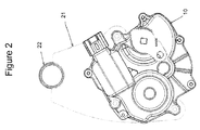
- Figure 2 illustrates an exemplary embodiment of the two way motion actuator 10.
- the two way motion actuator 10 is a motor which rotates in both a clockwise and counterclockwise (anticlockwise) direction.
- the two way motion actuator 10 is here described as an electric motor, but could also be another type of electric actuator with multiple positions such as a piston or solenoid.
- the two way motion actuator 10 is not limited to just two motions but rather includes at least two motions.
- Push pull link 11 is attached to the actuator 10, as illustrated in Figure 3 .
- the push pull link 11 moves away from the two way motion actuator 10.
- the dashed outline of the push pull link 11 illustrates the motion of the push pull link 11 after the two way motion actuator 10 has rotated in the counterclockwise direction.
- FIG 4 illustrates that the other end of the push pull link 11 that is not attached to the two way motion actuator 10 is attached to a rotation link 12 at a bottom part thereof.
- the rotation link 12 is roughly triangular in shape illustrated in Figure 4 but the particular configuration of the rotation link 12 can be changed to fit various geometries.
- Figure 4 shows the motion of the rotation link 12 by the push pull link 11.
- the push pull link 11 moves the rotation link 12 from a first position to a second position illustrated in Figure 4 by a dashed line.
- the rotation link is moved rightward in Figure 4 by the movement of the two way motion actuator 10.
- Half tube 13 is attached at an upper portion of the rotation link 12.
- the half tube 13 may be in the shape of an extruded, hollowed-out semicircle.
- the half tube 13 is essentially the shape of a pipe which has been cut in half along its axial direction.
- An end of the half tube 13 in the axial direction is connected to an inboard side of a center rotation link 14, which is illustrated in Figure 5 .
- An upper portion of the center rotation link 14 includes a riveting 15 which rotatably attaches the center rotation link 14 to the recliner pull link 16.
- the recliner pull link 16 extends between the center rotation link 14 and the recliner release lever 19.
- the recliner pull link 16 extend substantially in the fore-aft direction of the vehicle. Discussed above, the recliner pull link 16 is attached to the center rotation link 14 by riveting 15. When the center rotation link 14 is moved by the two way motion actuator 10 (via the push pull link 11, the rotation link 12, and the half tube 13), the recliner pull link 16 is moved. The recliner pull link 16 is moved leftward as shown in Figure 5 , illustrated by the dashed line.
- the recliner pull link 16 includes a slot hole 17 located at the end of the recliner pull link 16 opposite the end attached to the center rotation link 14.
- the slot hole 17 is formed substantially in the same length direction of the recliner link 16.
- the slot hole 17 is provided with a riveting 18 which is able to slide the length of the slot hole 17. That is, the riveting 18 is able to travel the length of the slot hole 17 depending on the movement of the recliner pull link 16.
- the riveting 18 is attached to recliner release lever 19 as shown in Figures 1 and 7 .
- the recliner release lever 19 has an approximately triangular shape with the riveting 18 located at a bottom portion thereof. However, the shape of the recliner release lever can be modified as necessary for the geometry of the seat apparatus.
- the recliner release lever is connected to the recliner connecting tube 20.
- the recliner connecting tube 20 being connected to a recliner mechanism (not illustrated) in order to release the recliner from a locked state.
- the two way movement actuator 10 releases the recliner from a locked state via the mechanism described above.
- the two way motion actuator 10 moves in a first direction to push the push pull link 11.
- the push pull link 11 moves the rotation link 12 which moves the center rotation link 14 via the half tube 13.
- the center rotation link 14 pulls the recliner pull link 16 via the riveting 15.
- the direction of movement is leftward as illustrated in Figure 5 .
- the recliner pull link 16 begins to act on the riveting 18 once the recliner pull link 16 is pulled a sufficient distance for the riveting 18 to reach the end of the slot hole 18.
- the recliner is released from the locked state by movement of the two way motion actuator 10 moving in a first direction. Once the recliner is released form the locked state, a user may manually adjust the recline angle of the seat.
- Figure 8 is a view of the same two way motion actuator 10 shown in Figure 3 .
- Figure 8 shows the two way motion actuator 10 moving in a second direction as illustrated by the dashed lines.
- the second direction corresponds to a clockwise rotation of the two way motion actuator which correspondingly pulls the push pull link 11 primarily leftward in Figure 8 .
- the two way motion actuator is not limited to a rotational motion and the first and second directions are not limited to clockwise and counterclockwise movements.
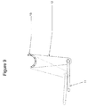
- FIG. 9 The movement of the two way motion actuator 10 in the second direction pulls the rotation link 12 and half tube 13 as illustrated in Figure 9 .
- the dashed lines of Figure 9 illustrate this movement of the rotation link 12.
- the rotation link 12 moves primarily leftward in Figure 9 due to the movement of the two way motion actuator 10 in the second direction.
- Figure 4 illustrates the movement of the rotation link 12 primarily rightward based on the pushing of the push pull link 11 when the two way motion actuator operates in the first direction.
- Figure 10 illustrates that movement of rotation link 12 causes the center rotation link 14 to rotate via the connection of the half tube 13 between the rotation link 12 and center rotation link 14. This rotation is illustrated by a dashed line in Figure 10.
- Figure 10 can be compared to the rotation of the center link 14 illustrated in Figure 5 .
- the center rotation link 14 rotates in the counterclockwise position due to the movement of the two way motion actuator 10 moving in the first direction.
- Figure 10 illustrates that the center rotation link 14 rotates in the clockwise direction due to the movement of the two way motion actuator 10 moving in the second direction.
- the slide pin 31 extends through a slot hole 38 provided to the slide release lever 30.
- the slot hole 38 is illustrated in the figures has have an arc shaped. However, the slot hole 38 is not limited to such a shape.
- Figure 11 illustrates that the rotation of the center rotation link caused by the two way motion actuator moving the second direction illustrated by the dashed line (see also Figure 10 ).
- the slide pin 31 moves in a generally downward direction caused by the movement (rotation) of the center rotation link 14 described above.
- the slide pin 31 moves it travels within the slot hole 38 provided to the slide release lever 30.
- contact will be made with the end of the slot hole 38 located downward in Figure 11 .
- the axis of rotation is the center caulking pin 32 as viewed in Figure 1 .
- Figure 13 shows that when the slide release lever moves a sufficient distance that the lock pin 37, located at an end of the slide release lever 30, releases from the lock lever 36.
- the lock lever pin 37 extends inwardly as partially illustrated by Figure 1 .
- the track slide (not pictured) is able to move.
- Figure 14 illustrates a second slide release lever 35 which is connected to the slide release lever 30 by center rotation tube 33.
- Caulking pin 32 attaches the slide release lever 30 to the center rotation tube 33.
- caulking pin 34 attaches the slide release lever 35 to the center rotation tube 33.
- the slide release lever 30 and slide release lever 35 can be called a first and second slide release lever, respectively.
- the slide release lever 35 includes a lock lever pin (unnumbered) that extends inwardly as illustrated in Figure 1 .
- the slide release lever 35 moves a sufficient distance the included lock lever pin releases from the associated lock lever (not illustrated). Accordingly, the track slide on both sides of the seat are released and the seat is free to slide in the fore-aft direction.
- a user may manually adjust the location of the seat in the fore-aft direction.
- the two way movement actuator 10 releases the slide mechanism from a locked state.
- the two way motion actuator 10 moves in a second direction to pull the push pull link 11.
- the push pull link 11 moves the rotation link 12 which moves the center rotation link 14 via the half tube 13.
- the center rotation link 14 includes a slide pin 31 which moves within a slot hole 38 of the slide release lever 30. Movement of the center rotation link 14 therefore pushes the slide release lever 30 downward as illustrated in Figure 11 once the slide pin 31 reaches the end of the slot hole 38.
- the slide release lever 30 moves a sufficient distance to release the lock lever pin 37 from the lock lever 36.
- the slide release lever 35 releases the associated lock lever pin 37 from the opposite lock lever. Accordingly, the slide mechanism is released from the locked state by movement of the two way motion actuator 10 moving in the second direction.
- the two way motion actuator 10 can release both the recline mechanism and the slide mechanism depending on whether the two way motion actuator 10 moves in the first direction or in the second direction.
- Figures 6 and 12 will now be used to describe how unintentional release of the respective slide mechanism and recliner mechanism is prevented when the respective other mechanism is released.
- Figure 6 illustrates the movement of the center rotation link 14 when the two way motion actuator is moved in the first direction to release the recliner mechanism (see also Figure 5 ).
- the center rotation link 14 moves leftward shown in the dashed line due to the two way motion actuator 10 moving in the first direction.
- the slide pin 31 moves within the slot hole 38 of the slide release lever 30.
- the slide pin 31 moves primarily upward in the slot hole 38. Therefore, the slide release lever does not move downward as shown in Figure 11 to release the slide mechanism. That is, the slide pin 31 never travels to the downward end of the slot hole 38 in order to push the slide release lever 30 in the downward direction to release the slide mechanism.
- the arrangement of the slide pin 31 and the slot hole 38 prevents unintended release of the slide mechanism when the two way motion actuator 10 is moved in the first direction to release the recliner mechanism. That is, the movement of slide mechanism is canceled by the above arrangement of the slide pin 31 and the slot hole 38.
- the slot hole 38 in combination with the rest of the recliner mechanism may be referred to as a first unintentional movement prevention device.
- slide release lever 35 Due to the connection of slide release lever 35 to the slide release lever 30 via the center rotation tube, the slide release lever 35 is similarly prevented from unintended release when the two way motion actuator 10 is moved in the first direction to release the recliner mechanism.
- Figure 12 illustrates the movement of the recliner pull link 16 when the two way motion actuator 10 moves in the second direction. Described above, when the two way motion actuator 10 moves in the second direction, the center rotation link rotates clockwise and moves downward as shown in Figure 11.
- Figure 12 shows that when the center rotation link 14 rotates clockwise, the recliner pull link 16 is pushed rightward as shown by the dashed line. Due to the rightward motion of the recliner pull link 16, the riveting 18 slides in the slot hole 17 towards the leftmost end of the slot hole 18 (as shown in Figure 12 ). Therefore, the recliner pull link does not pull the recliner release lever 19 via the riveting 19 to release the recliner mechanism as shown in Figure 7 .
- the arrangement of the riveting 18 and the slot hole 17 prevents unintended release of the recliner mechanism when the two way motion actuator 10 is moved in the second direction to release the sliding mechanism. That is, the movement of recliner mechanism is canceled by the above arrangement of the riveting 18 and the slot hole 17.
- the slot hole 17 in combination with the rest of the recliner mechanism may be referred to as a second unintentional movement prevention device.
- the mechanism described in detail above can release both the slide mechanism and the recliner mechanism using a single actuator. Moreover, unintentional release of the slide mechanism is prevented when the user intends to operate the recliner release. Similarly, unintentional release of the recliner mechanism is prevented when the user intends to operate the slide release.
- the mechanism described above has an additional safety feature. That is, if electric power is disconnected from the two way motion actuator then each of the recliner release mechanism and the slide release mechanism are placed in a locked state.
- This feature is made possible as the locking mechanisms for recline and slide use springs to force the respective lock mechanisms into a locked state when not being released as described above. Thus, a spring force is used to hold the respective actuators in an initial position.
- the two way motion actuator 10 When the two way motion actuator 10 releases the slide mechanism, the two way motion actuator 10 pushes against the slide lock mechanisms including the springs to unlock the seat. If power is disconnected from the two way motion actuator during this operation, the spring force will push the actuator back into its initial state at the same time as locking the seat slide.
- the two way motion actuator 10 When the two way motion actuator 10 releases the recline mechanism, the two way motion actuator 10 pushes against the recliner lock mechanisms including the springs to unlock the seat. If power is disconnected from the two way motion actuator 10 during this operation, the spring force will push the actuator back into its initial state at the same time as locking the seat recliners.
- a single, cost effective and low mass, mechanism can safely release both the recliner mechanism and the slide mechanism of a vehicle seat.
- Such a system provides a more luxurious feeling than a purely manual mechanism in a cost effective manner compared to a fully power seat. Further, this system provides additional safety benefits when power is disconnected from the seat.
Abstract
Description
- Exemplary aspects of the present invention relate to the locking and releasing of a recliner mechanism and a slide mechanism of a vehicle seat and in particular to electrically actuating the release of these mechanisms.
- Seats of a vehicle such as an automobile may be provided with a reclining mechanism that allows the seat back to pivot at a base portion thereof. This reclining mechanism may have several defined positions including: a neutral position, an upright position, a rear most position, and a front most position.
- Seat of a vehicle such as an automobile may also be provided with a sliding mechanism that allows the seat to travel in the fore-aft direction of the vehicle.
- This sliding movement allows the seat occupant to find the optimal seat location. For example, the occupant may be a driver of the vehicle and the sliding mechanism is used to insure the drive is adequately placed to reach all of the vehicle controls.
- Both the reclining mechanism and the sliding mechanism may be operated using individual manual levers, typically located on the vehicle seat. Also the reclining mechanism and the sliding mechanism may be replaced by an actuator that performs the sliding and reclining functions without additional effort from the user. Seats equipped with these features are typically called power seats or power assisted seats.
- The actuators above provide convenience and a luxury feeling compared to the manual levers described above. However, these individual actuators and the associated mechanisms to effect the releases are complicated and high mass.
- A release mechanism of a seat, including a two way motion actuator that moves in both a first direction and in a second direction; a recliner release mechanism that releases a recliner of the seat in response to the two way motion actuator moving in the first direction; and a slide release mechanism that releases a slide mechanism of the seat in response to the two way motion actuator moving in the second direction.
- The two way motion actuator can be a motor and the first direction a first rotation direction of the motor; the second direction can be a second rotation direction of the motor.
- In a particular embodiment, the release mechanism further comprises a first unintentional movement prevention device that prevents the slide mechanism from moving when the two way motion actuator moves in the first direction; and a second unintentional movement prevention device that prevents the recliner from moving when the two way motion actuator moves in the second direction.
- The first unintentional movement prevention device and the second unintentional movement prevention device can be slot holes.
- The release mechanism can comprise a push pull link that extends from the two way motion actuator to a rotation link, the rotation link rotating in response to movement by the two way motion actuator; and a center rotation link that is connected to the rotation link by a half tube that extends from the rotation link.
- In a particular embodiment, the recliner release mechanism can include a recliner release lever that releases the recliner of the seat, and a recliner pull link that is connected to the center rotation link by a first riveting and connected to the recliner release lever by a second riveting.
- A recliner pull link can include a first slot hole in which the second riveting is configured to slide.
- In a particular embodiment, the first unintentional movement prevention device is the first slot hole and when the two way motion actuator moves in the first direction the second riveting contacts an end of the first slot hole so that the recliner pull link moves the recliner release lever and when the two way motion actuator moves in the second direction the second riveting slides within the first slot hole and recliner release lever is unmoved by the center rotation link.
- The slide release mechanism can include a slide release lever that releases the slide mechanism of the seat, the slide release lever being connected to the to the center rotation link by a slide pin that extends from the center rotation link.
- The slide release lever can include a second slot hole in which the slide pin is configured to slide.
- In a particular embodiment, the second unintentional movement prevention device is the second slot hole and when the two way motion actuator moves in the second direction the slide pin contacts an end of the second slot hole so that the slide release lever is moved to release the slide mechanism and when the two way motion actuator moves in the first direction the slide pin slides within the second slot hole and slide release lever is unmoved by the center rotation link.
- In a further embodiment, if electric power is disconnected from the two way motion actuator then each of the recliner release mechanism and the slide release mechanism are placed in a locked state.
- A more complete appreciation of the invention and many of the attendant advantages thereof will be readily obtained as the same becomes better understood by reference to the following detailed description when considered in connection with the accompanying drawings.
-
Figure 1 illustrates a view of a recliner mechanism and sliding mechanism of a vehicle seat in accordance with an exemplary aspect of the disclosure. -
Figure 2 illustrates a view of an exemplary actuator. -
Figure 3 illustrates a view a recliner mechanism in accordance with an exemplary aspect of the disclosure. -
Figure 4 illustrates a view a recliner mechanism in accordance with an exemplary aspect of the disclosure. -
Figure 5 illustrates a view a recliner mechanism in accordance with an exemplary aspect of the disclosure. -
Figure 6 illustrates a view a sliding mechanism in accordance with an exemplary aspect of the disclosure. -
Figure 7 illustrates a view a recliner mechanism in accordance with an exemplary aspect of the disclosure. -
Figure 8 illustrates a view a sliding mechanism in accordance with an exemplary aspect of the disclosure. -
Figure 9 illustrates a view a sliding mechanism in accordance with an exemplary aspect of the disclosure. -
Figure 10 illustrates a view a sliding mechanism in accordance with an exemplary aspect of the disclosure. -
Figure 11 illustrates a view a sliding mechanism in accordance with an exemplary aspect of the disclosure. -
Figure 12 illustrates a view a sliding mechanism in accordance with an exemplary aspect of the disclosure. -
Figure 13 illustrates a view a sliding mechanism in accordance with an exemplary aspect of the disclosure. -
Figure 14 illustrates a view a sliding mechanism in accordance with an exemplary aspect of the disclosure. - Referring now to the drawings, wherein like reference numerals designate identical or corresponding parts throughout the several views. Further, as used herein, the words "a," "an" and the like generally carry a meaning of "one or more," unless stated otherwise.
-
Figures 1-14 depict various aspects of a recliner mechanism and a sliding mechanism for a vehicle seat. Here a vehicle refers to a land vehicle exemplified by an automobile. However, the present disclosure is also applicable to any similar type vehicle, such as but not limited to, a sport utility vehicle, a pickup truck, a commercial vehicle or the like. -
Figure 1 illustrates schematically a vehicle a recliner mechanism and a sliding mechanism in accordance with the present disclosure. A partially illustrated seat includes a twoway motion actuator 10 attached to anattachment plate 21. Theattachment plate 21 attaches to afront torsion tube 22, which attaches to a seat frame (not illustrated). - The seat includes
upper rails 24 and 26 which extend in the fore-aft direction of the vehicle. Theupper rails 24 and 26 slide in the fore-aft direction relative to lower rails (not illustrated). The twoway motion actuator 10 is located inward of the upper rail 24. -
Figure 2 illustrates an exemplary embodiment of the twoway motion actuator 10. Here, the twoway motion actuator 10 is a motor which rotates in both a clockwise and counterclockwise (anticlockwise) direction. The twoway motion actuator 10 is here described as an electric motor, but could also be another type of electric actuator with multiple positions such as a piston or solenoid. The twoway motion actuator 10 is not limited to just two motions but rather includes at least two motions. -
Push pull link 11 is attached to theactuator 10, as illustrated inFigure 3 . When the twoway motion actuator 10 moves in a first direction (illustrated as counterclockwise inFigure 3 ) thepush pull link 11 moves away from the twoway motion actuator 10. The dashed outline of thepush pull link 11 illustrates the motion of thepush pull link 11 after the twoway motion actuator 10 has rotated in the counterclockwise direction. -
Figure 4 illustrates that the other end of thepush pull link 11 that is not attached to the twoway motion actuator 10 is attached to arotation link 12 at a bottom part thereof. Therotation link 12 is roughly triangular in shape illustrated inFigure 4 but the particular configuration of therotation link 12 can be changed to fit various geometries. -
Figure 4 shows the motion of therotation link 12 by thepush pull link 11. In particular, when the twoway motion actuator 10 moves from the first position to the second position thepush pull link 11 moves therotation link 12 from a first position to a second position illustrated inFigure 4 by a dashed line. As shown inFigure 4 , the rotation link is moved rightward inFigure 4 by the movement of the twoway motion actuator 10. -
Half tube 13 is attached at an upper portion of therotation link 12. Thehalf tube 13 may be in the shape of an extruded, hollowed-out semicircle. Thehalf tube 13 is essentially the shape of a pipe which has been cut in half along its axial direction. - An end of the
half tube 13 in the axial direction is connected to an inboard side of acenter rotation link 14, which is illustrated inFigure 5 . An upper portion of thecenter rotation link 14 includes a riveting 15 which rotatably attaches the center rotation link 14 to therecliner pull link 16. - The
recliner pull link 16 extends between thecenter rotation link 14 and therecliner release lever 19. Therecliner pull link 16 extend substantially in the fore-aft direction of the vehicle. Discussed above, therecliner pull link 16 is attached to thecenter rotation link 14 by riveting 15. When thecenter rotation link 14 is moved by the two way motion actuator 10 (via thepush pull link 11, therotation link 12, and the half tube 13), therecliner pull link 16 is moved. Therecliner pull link 16 is moved leftward as shown inFigure 5 , illustrated by the dashed line. - The
recliner pull link 16 includes aslot hole 17 located at the end of therecliner pull link 16 opposite the end attached to thecenter rotation link 14. Theslot hole 17 is formed substantially in the same length direction of therecliner link 16. Theslot hole 17 is provided with a riveting 18 which is able to slide the length of theslot hole 17. That is, the riveting 18 is able to travel the length of theslot hole 17 depending on the movement of therecliner pull link 16. - The riveting 18 is attached to
recliner release lever 19 as shown inFigures 1 and7 . Therecliner release lever 19 has an approximately triangular shape with the riveting 18 located at a bottom portion thereof. However, the shape of the recliner release lever can be modified as necessary for the geometry of the seat apparatus. The recliner release lever is connected to therecliner connecting tube 20. Therecliner connecting tube 20 being connected to a recliner mechanism (not illustrated) in order to release the recliner from a locked state. - As shown in the
Figures 1-7 , the twoway movement actuator 10 releases the recliner from a locked state via the mechanism described above. In particular, the twoway motion actuator 10 moves in a first direction to push thepush pull link 11. The push pulllink 11 moves therotation link 12 which moves thecenter rotation link 14 via thehalf tube 13. Thecenter rotation link 14 pulls therecliner pull link 16 via the riveting 15. The direction of movement is leftward as illustrated inFigure 5 . When therecliner pull link 16 is pulled by therotation link 14, therecliner pull link 16 begins to act on the riveting 18 once therecliner pull link 16 is pulled a sufficient distance for the riveting 18 to reach the end of theslot hole 18. Once the riveting 18 contacts the end of theslot hole 17 that is opposite thecenter rotation link 14, further movement of therecliner pull link 16 will pull therecliner release plate 19 via the riveting 18. Accordingly, the recliner is released from the locked state by movement of the twoway motion actuator 10 moving in a first direction. Once the recliner is released form the locked state, a user may manually adjust the recline angle of the seat. - A slide release mechanism will be described referring primarily to
Figures 8-14 .Figure 8 is a view of the same twoway motion actuator 10 shown inFigure 3 . However,Figure 8 shows the twoway motion actuator 10 moving in a second direction as illustrated by the dashed lines. The second direction corresponds to a clockwise rotation of the two way motion actuator which correspondingly pulls thepush pull link 11 primarily leftward inFigure 8 . As described above, the two way motion actuator is not limited to a rotational motion and the first and second directions are not limited to clockwise and counterclockwise movements. - The movement of the two
way motion actuator 10 in the second direction pulls therotation link 12 andhalf tube 13 as illustrated inFigure 9 . The dashed lines ofFigure 9 illustrate this movement of therotation link 12. As shown inFigure 9 , therotation link 12 moves primarily leftward inFigure 9 due to the movement of the twoway motion actuator 10 in the second direction. In contrast,Figure 4 illustrates the movement of therotation link 12 primarily rightward based on the pushing of thepush pull link 11 when the two way motion actuator operates in the first direction. -
Figure 10 illustrates that movement ofrotation link 12 causes the center rotation link 14 to rotate via the connection of thehalf tube 13 between therotation link 12 andcenter rotation link 14. This rotation is illustrated by a dashed line inFigure 10. Figure 10 can be compared to the rotation of thecenter link 14 illustrated inFigure 5 . InFigure 5 , thecenter rotation link 14 rotates in the counterclockwise position due to the movement of the twoway motion actuator 10 moving in the first direction. In contrast,Figure 10 illustrates that thecenter rotation link 14 rotates in the clockwise direction due to the movement of the twoway motion actuator 10 moving in the second direction. - Extending from the
center rotation link 14 isslide pin 31. Theslide pin 31 extends through aslot hole 38 provided to theslide release lever 30. These features can be seen inFigures 1 ,11 ,13 , and14 . Theslot hole 38 is illustrated in the figures has have an arc shaped. However, theslot hole 38 is not limited to such a shape. -
Figure 11 illustrates that the rotation of the center rotation link caused by the two way motion actuator moving the second direction illustrated by the dashed line (see alsoFigure 10 ). InFigure 11 , theslide pin 31 moves in a generally downward direction caused by the movement (rotation) of the center rotation link 14 described above. As theslide pin 31 moves it travels within theslot hole 38 provided to theslide release lever 30. When theslide pin 31 travels a sufficient distance within theslot hole 38, contact will be made with the end of theslot hole 38 located downward inFigure 11 . At this point, further movement of theslide pin 31 caused by the rotation of thecenter rotation link 14 will cause theslide release lever 30 to rotate. The axis of rotation is thecenter caulking pin 32 as viewed inFigure 1 . - The movement of the
slide release lever 30 caused by theslide pin 31 is illustrated by a dashed line inFigure 11 . Theslide release lever 30 moves in a downward direction as illustrated inFigure 11 .Figure 13 shows an additional view of this movement. -
Figure 13 shows that when the slide release lever moves a sufficient distance that thelock pin 37, located at an end of theslide release lever 30, releases from thelock lever 36. Thelock lever pin 37 extends inwardly as partially illustrated byFigure 1 . When thelock lever pin 37 is released fromlock lever 36 the track slide (not pictured) is able to move. -
Figure 14 illustrates a secondslide release lever 35 which is connected to theslide release lever 30 bycenter rotation tube 33.Caulking pin 32 attaches theslide release lever 30 to thecenter rotation tube 33. Similarly,caulking pin 34 attaches theslide release lever 35 to thecenter rotation tube 33. Theslide release lever 30 andslide release lever 35 can be called a first and second slide release lever, respectively. - Therefore, any movement imparted to the
slide release lever 30 by theslide pin 31 also moves theslide release lever 35 via thecenter rotation tube 33. Theslide release lever 35 includes a lock lever pin (unnumbered) that extends inwardly as illustrated inFigure 1 . when theslide release lever 35 moves a sufficient distance the included lock lever pin releases from the associated lock lever (not illustrated). Accordingly, the track slide on both sides of the seat are released and the seat is free to slide in the fore-aft direction. Once the slide mechanism is released form the locked state, a user may manually adjust the location of the seat in the fore-aft direction. - Described above, the two
way movement actuator 10 releases the slide mechanism from a locked state. In particular, the twoway motion actuator 10 moves in a second direction to pull thepush pull link 11. The push pulllink 11 moves therotation link 12 which moves thecenter rotation link 14 via thehalf tube 13. Thecenter rotation link 14 includes aslide pin 31 which moves within aslot hole 38 of theslide release lever 30. Movement of the center rotation link 14 therefore pushes theslide release lever 30 downward as illustrated inFigure 11 once theslide pin 31 reaches the end of theslot hole 38. Theslide release lever 30 moves a sufficient distance to release thelock lever pin 37 from thelock lever 36. Simultaneously, theslide release lever 35 releases the associatedlock lever pin 37 from the opposite lock lever. Accordingly, the slide mechanism is released from the locked state by movement of the twoway motion actuator 10 moving in the second direction. - As described above, the two
way motion actuator 10 can release both the recline mechanism and the slide mechanism depending on whether the twoway motion actuator 10 moves in the first direction or in the second direction.Figures 6 and12 will now be used to describe how unintentional release of the respective slide mechanism and recliner mechanism is prevented when the respective other mechanism is released. -
Figure 6 illustrates the movement of thecenter rotation link 14 when the two way motion actuator is moved in the first direction to release the recliner mechanism (see alsoFigure 5 ). As shown inFigure 6 , the center rotation link 14 moves leftward shown in the dashed line due to the twoway motion actuator 10 moving in the first direction. Due to the movement of thecenter rotation link 14, theslide pin 31 moves within theslot hole 38 of theslide release lever 30. Here, theslide pin 31 moves primarily upward in theslot hole 38. Therefore, the slide release lever does not move downward as shown inFigure 11 to release the slide mechanism. That is, theslide pin 31 never travels to the downward end of theslot hole 38 in order to push theslide release lever 30 in the downward direction to release the slide mechanism. Accordingly, the arrangement of theslide pin 31 and theslot hole 38 prevents unintended release of the slide mechanism when the twoway motion actuator 10 is moved in the first direction to release the recliner mechanism. That is, the movement of slide mechanism is canceled by the above arrangement of theslide pin 31 and theslot hole 38. Theslot hole 38 in combination with the rest of the recliner mechanism may be referred to as a first unintentional movement prevention device. - Due to the connection of
slide release lever 35 to theslide release lever 30 via the center rotation tube, theslide release lever 35 is similarly prevented from unintended release when the twoway motion actuator 10 is moved in the first direction to release the recliner mechanism. -
Figure 12 illustrates the movement of therecliner pull link 16 when the twoway motion actuator 10 moves in the second direction. Described above, when the twoway motion actuator 10 moves in the second direction, the center rotation link rotates clockwise and moves downward as shown inFigure 11. Figure 12 shows that when thecenter rotation link 14 rotates clockwise, therecliner pull link 16 is pushed rightward as shown by the dashed line. Due to the rightward motion of therecliner pull link 16, the riveting 18 slides in theslot hole 17 towards the leftmost end of the slot hole 18 (as shown inFigure 12 ). Therefore, the recliner pull link does not pull therecliner release lever 19 via the riveting 19 to release the recliner mechanism as shown inFigure 7 . Accordingly, the arrangement of the riveting 18 and theslot hole 17 prevents unintended release of the recliner mechanism when the twoway motion actuator 10 is moved in the second direction to release the sliding mechanism. That is, the movement of recliner mechanism is canceled by the above arrangement of the riveting 18 and theslot hole 17. Theslot hole 17 in combination with the rest of the recliner mechanism may be referred to as a second unintentional movement prevention device. - Accordingly, the mechanism described in detail above can release both the slide mechanism and the recliner mechanism using a single actuator. Moreover, unintentional release of the slide mechanism is prevented when the user intends to operate the recliner release. Similarly, unintentional release of the recliner mechanism is prevented when the user intends to operate the slide release.
- Additionally, the mechanism described above has an additional safety feature. That is, if electric power is disconnected from the two way motion actuator then each of the recliner release mechanism and the slide release mechanism are placed in a locked state. This feature is made possible as the locking mechanisms for recline and slide use springs to force the respective lock mechanisms into a locked state when not being released as described above. Thus, a spring force is used to hold the respective actuators in an initial position.
- When the two
way motion actuator 10 releases the slide mechanism, the twoway motion actuator 10 pushes against the slide lock mechanisms including the springs to unlock the seat. If power is disconnected from the two way motion actuator during this operation, the spring force will push the actuator back into its initial state at the same time as locking the seat slide. - When the two
way motion actuator 10 releases the recline mechanism, the twoway motion actuator 10 pushes against the recliner lock mechanisms including the springs to unlock the seat. If power is disconnected from the twoway motion actuator 10 during this operation, the spring force will push the actuator back into its initial state at the same time as locking the seat recliners. - Thus, a single, cost effective and low mass, mechanism can safely release both the recliner mechanism and the slide mechanism of a vehicle seat. Such a system provides a more luxurious feeling than a purely manual mechanism in a cost effective manner compared to a fully power seat. Further, this system provides additional safety benefits when power is disconnected from the seat.
- Obviously, numerous modifications and variations of the present invention are possible in light of the above teachings. It is therefore to be understood that within the scope of the appended claims, the invention may be practiced otherwise than as specifically described herein.
Claims (12)
- A release mechanism of a seat, comprising:a two way motion actuator (10) that moves in both a first direction and in a second direction;a recliner release mechanism (19, 20) that releases a recliner of the seat in response to the two way motion actuator (10) moving in the first direction; anda slide release mechanism (30, 33, 35) that releases a slide mechanism of the seat in response to the two way motion actuator (10) moving in the second direction.
- The release mechanism of the seat according to claim 1, wherein the two way motion actuator (10) is a motor and the first direction is a first rotation direction of the motor and the second direction is a second rotation direction of the motor.
- The release mechanism of the seat according to claim 1 or 2, further comprising:a first unintentional movement prevention device that prevents the slide mechanism (30, 33, 35) from moving when the two way motion actuator (10) moves in the first direction; anda second unintentional movement prevention device that prevents the recliner (19,20) from moving when the two way motion actuator (10) moves in the second direction.
- The release mechanism of the seat according to claim 3, wherein the first unintentional movement prevention device and the second unintentional movement prevention device are slot holes (17, 38).
- The release mechanism of the seat according to claim 3 or 4, further comprising:a push pull link (11) that extends from the two way motion actuator (10) to a rotation link (12), the rotation link (12) rotating in response to movement by the two way motion actuator (10); anda center rotation link (14) that is connected to the rotation link (12) by a half tube (13) that extends from the rotation link (12).
- The release mechanism of the seat according to claim 5, wherein the recliner release mechanism (19, 20) includes a recliner release lever (19) that releases the recliner of the seat, and a recliner pull link (16) that is connected to the center rotation link (14) by a first riveting (15) and connected to the recliner release lever (19) by a second riveting (18).
- The release mechanism of the seat according to claim 6, wherein the recliner pull link (16) includes a first slot hole (17) in which the second riveting (18) is configured to slide.
- The release mechanism of the seat according to claim 6 or 7, wherein the first unintentional movement prevention device is the first slot hole (17) and when the two way motion actuator (10) moves in the first direction the second riveting (18) contacts an end of the first slot hole (17) so that the recliner pull link (16) moves the recliner release lever (19) and when the two way motion actuator (10) moves in the second direction the second riveting (18) slides within the first slot hole (17) and recliner release lever (19) is unmoved by the center rotation link (14).
- The release mechanism of the seat according to claim 5, wherein the slide release mechanism (30, 33, 35) includes a slide release lever (30) that releases the slide mechanism of the seat, and the slide release lever (30) is connected to the to the center rotation link (14) by a slide pin (31) that extends from the center rotation link (14).
- The release mechanism of the seat according to claim 9, wherein the slide release lever (30) includes a second slot hole (38) in which the slide pin (31) is configured to slide.
- The release mechanism of the seat according to claim 10, wherein the second unintentional movement prevention device is the second slot hole (38) and when the two way motion actuator (10) moves in the second direction the slide pin (31) contacts an end of the second slot hole (38) so that the slide release lever (30) is moved to release the slide mechanism and when the two way motion actuator (10) moves in the first direction the slide pin slides within the second slot hole (38) and slide release lever (30) is unmoved by the center rotation link.
- The release mechanism of the seat according to any of claims 1 to 11, wherein if electric power is disconnected from the two way motion actuator (10) then each of the recliner release mechanism (19, 20) and the slide release mechanism (30, 33, 35) are placed in a locked state.
Applications Claiming Priority (1)
| Application Number | Priority Date | Filing Date | Title |
|---|---|---|---|
| US13/856,270 US9061606B2 (en) | 2013-04-03 | 2013-04-03 | Electric release manual seat |
Publications (2)
| Publication Number | Publication Date |
|---|---|
| EP2786893A2 true EP2786893A2 (en) | 2014-10-08 |
| EP2786893A3 EP2786893A3 (en) | 2017-11-29 |
Family
ID=50349545
Family Applications (1)
| Application Number | Title | Priority Date | Filing Date |
|---|---|---|---|
| EP14161992.4A Withdrawn EP2786893A3 (en) | 2013-04-03 | 2014-03-27 | Electric release manual seat |
Country Status (3)
| Country | Link |
|---|---|
| US (1) | US9061606B2 (en) |
| EP (1) | EP2786893A3 (en) |
| JP (1) | JP5795397B2 (en) |
Cited By (2)
| Publication number | Priority date | Publication date | Assignee | Title |
|---|---|---|---|---|
| EP3112273A1 (en) * | 2015-06-29 | 2017-01-04 | The Boeing Company | Efficient stationkeeping design for mixed fuel systems in response to a failure of an electric thruster |
| FR3043954A1 (en) * | 2015-11-24 | 2017-05-26 | Faurecia Sieges D'automobile | VEHICLE SEAT AND METHOD OF ADJUSTING A VEHICLE SEAT |
Families Citing this family (4)
| Publication number | Priority date | Publication date | Assignee | Title |
|---|---|---|---|---|
| DE102013103662A1 (en) * | 2013-04-11 | 2014-10-16 | Airbus Operations Gmbh | Holding device for passenger seats and passenger seating system with flexible seat arrangement for passenger transport means |
| DE102015204273A1 (en) * | 2015-03-10 | 2016-09-15 | Brose Fahrzeugteile Gmbh & Co. Kg, Coburg | Vehicle seat with easy-entry function |
| DE102018208641B4 (en) * | 2018-05-30 | 2023-04-27 | Brose Fahrzeugteile SE & Co. Kommanditgesellschaft, Coburg | Vehicle seat with power-actuated adjustable swing arm component and locking unit |
| US10857910B2 (en) | 2018-12-17 | 2020-12-08 | Lear Corporation | Vehicle seating system |
Family Cites Families (36)
| Publication number | Priority date | Publication date | Assignee | Title |
|---|---|---|---|---|
| US4615232A (en) * | 1982-12-30 | 1986-10-07 | J. I. Case Company | Control linkage |
| GB8402775D0 (en) | 1984-02-02 | 1984-03-07 | Lucas Ind Plc | Brake actuator |
| US4653807A (en) * | 1984-05-18 | 1987-03-31 | Mazda Motor Corporation | Adjustable seat assembly |
| JPS60184734U (en) * | 1984-05-18 | 1985-12-07 | マツダ株式会社 | car seat equipment |
| US4634180A (en) * | 1984-08-06 | 1987-01-06 | Keiper Recaro Incorporated | Vehicle easy entry seat latching mechanism |
| US5348373A (en) * | 1992-03-27 | 1994-09-20 | Hoover Universal, Inc. | Elecromechanical release mechanism for a seat assembly |
| US5292178A (en) * | 1992-07-15 | 1994-03-08 | General Motors Corporation | Front seat for two-door vehicle |
| US5683140A (en) * | 1995-12-19 | 1997-11-04 | Chrysler Corporation | Easy entry seat assembly system |
| US5813726A (en) * | 1997-02-18 | 1998-09-29 | Hoover Universal, Inc. | Inertia locking device for a vehicle seat adjustment mechanism |
| FR2778613B1 (en) * | 1998-05-12 | 2000-07-21 | Faure Bertrand Equipements Sa | SLIDE FOR VEHICLE SEAT WITH LONGITUDINAL ADJUSTMENT MEMORY AND SEAT COMPRISING SUCH A SLIDE |
| US6036267A (en) * | 1998-06-23 | 2000-03-14 | Dura Automotive Systems Inc. | Seat track with rotary locking device |
| US6443414B1 (en) * | 2000-10-18 | 2002-09-03 | Dura Global Technologies | Seat track assembly with release mechanism having a rotatable rod |
| EP2289734B2 (en) * | 2001-08-09 | 2018-07-04 | Virgin Atlantic Airways Limited | A seating system and a passenger seat unit for an aircraft |
| DE10151762B4 (en) * | 2001-10-19 | 2007-08-16 | C. Rob. Hammerstein Gmbh & Co. Kg | Predisplaceable motor vehicle seat with access to a rear seat through a front door |
| JP4103524B2 (en) * | 2002-09-30 | 2008-06-18 | アイシン精機株式会社 | Walk-in device for vehicle seat |
| US7152922B2 (en) * | 2004-05-07 | 2006-12-26 | Fisher Dynamics Corporation | Powered remote release actuator for a seat assembly |
| WO2006089191A1 (en) * | 2005-02-18 | 2006-08-24 | Johnson Controls Technology Company | Vehicle seating system |
| JP2006335148A (en) | 2005-05-31 | 2006-12-14 | Tachi S Co Ltd | Motorized lock device, and electric slide seat |
| KR100737599B1 (en) * | 2005-11-04 | 2007-07-10 | 현대자동차주식회사 | The Structure Of Pump'g Lever And Recliner Lever Has It All |
| JP4224069B2 (en) * | 2006-01-27 | 2009-02-12 | トヨタ自動車株式会社 | Sheet |
| JP4182984B2 (en) * | 2006-01-27 | 2008-11-19 | トヨタ自動車株式会社 | Sheet |
| JP4182983B2 (en) * | 2006-01-27 | 2008-11-19 | トヨタ自動車株式会社 | Sheet |
| US20080012411A1 (en) * | 2006-07-14 | 2008-01-17 | Lear Corporation | Vehicle seat adjusting assembly |
| US7703851B2 (en) * | 2006-09-21 | 2010-04-27 | Mazda Motor Corporation | Seat device |
| DE102006047398A1 (en) * | 2006-10-06 | 2008-05-21 | Lear Corporation, Southfield | 2-in-1-operating lever |
| JP5104853B2 (en) * | 2007-03-29 | 2012-12-19 | トヨタ紡織株式会社 | Vehicle seat |
| WO2008132998A1 (en) * | 2007-04-16 | 2008-11-06 | Toyota Boshoku Kabushiki Kaisha | Vehicle seat |
| DE102008017018A1 (en) * | 2007-06-29 | 2009-01-08 | C. Rob. Hammerstein Gmbh & Co. Kg | Retractable vehicle seat, especially for 2-door vehicles |
| CN101883697B (en) * | 2007-12-03 | 2012-08-15 | 丰田纺织株式会社 | Vehicle seat |
| US8172326B2 (en) * | 2008-03-14 | 2012-05-08 | Lear Corporation | Pivot joint assembly for a vehicle seat |
| JP5376203B2 (en) * | 2008-09-16 | 2013-12-25 | アイシン精機株式会社 | Electric seat system for vehicles |
| JP5332903B2 (en) * | 2009-05-26 | 2013-11-06 | アイシン精機株式会社 | Power seat speed reducer |
| JP4785011B2 (en) * | 2009-08-21 | 2011-10-05 | トヨタ紡織株式会社 | Vehicle seat |
| US8167372B2 (en) * | 2009-12-01 | 2012-05-01 | Toyota Motor Engineering & Manufacturing North America, Inc. | Seat assembly having dual actuated locking mechanism |
| US9227729B2 (en) * | 2013-04-08 | 2016-01-05 | B/E Aerospace, Inc. | Aircraft seat employing dual actuators for seat translaton and seat recline |
| US9156377B2 (en) * | 2013-05-14 | 2015-10-13 | AISIN Technical Center of America, Inc. | Power seat with complete manual walk-in system |
-
2013
- 2013-04-03 US US13/856,270 patent/US9061606B2/en active Active
-
2014
- 2014-03-04 JP JP2014041790A patent/JP5795397B2/en active Active
- 2014-03-27 EP EP14161992.4A patent/EP2786893A3/en not_active Withdrawn
Non-Patent Citations (1)
| Title |
|---|
| None |
Cited By (3)
| Publication number | Priority date | Publication date | Assignee | Title |
|---|---|---|---|---|
| EP3112273A1 (en) * | 2015-06-29 | 2017-01-04 | The Boeing Company | Efficient stationkeeping design for mixed fuel systems in response to a failure of an electric thruster |
| US9963249B2 (en) | 2015-06-29 | 2018-05-08 | The Boeing Company | Efficient stationkeeping design for mixed fuel systems in response to a failure of an electric thruster |
| FR3043954A1 (en) * | 2015-11-24 | 2017-05-26 | Faurecia Sieges D'automobile | VEHICLE SEAT AND METHOD OF ADJUSTING A VEHICLE SEAT |
Also Published As
| Publication number | Publication date |
|---|---|
| US9061606B2 (en) | 2015-06-23 |
| JP5795397B2 (en) | 2015-10-14 |
| JP2014201306A (en) | 2014-10-27 |
| EP2786893A3 (en) | 2017-11-29 |
| US20140300159A1 (en) | 2014-10-09 |
Similar Documents
| Publication | Publication Date | Title |
|---|---|---|
| EP2786893A2 (en) | Electric release manual seat | |
| EP2109553B1 (en) | Vehicle seat | |
| JP4845911B2 (en) | Hinge mechanism and vehicle seat having the mechanism | |
| EP2939872B1 (en) | Power seat with complete manual walk-in system | |
| CN111319527B (en) | Vehicle seating system | |
| US9315128B2 (en) | Vehicle seat and commercial vehicle with at least one vehicle seat | |
| CN108349412B (en) | Vehicle seat | |
| CA2786292C (en) | Seat assembly with easy-entry mechanism and fold flat feature | |
| WO2018076223A1 (en) | Headrest assembly and seat for motor vehicle | |
| US20160176323A1 (en) | Fitting with a pivoting-forwards mechanism and an easy-entry latch, and vehicle seat with such a fitting | |
| CN107444203B (en) | Seat adjusting device and vehicle seat | |
| US9156377B2 (en) | Power seat with complete manual walk-in system | |
| JP5889936B2 (en) | Vehicle seat device with intermediate return slide walk-in | |
| US10040375B2 (en) | Unlocking lever for a seat adjuster of a vehicle seat, and vehicle seat | |
| US11951883B2 (en) | Stow to floor seat assembly | |
| CN102602306B (en) | Vehicle seat easily enters system | |
| KR20180060396A (en) | Flat Seat for Vehicle | |
| JP4562605B2 (en) | Vehicle seat back-forward mechanism | |
| JP5905511B2 (en) | Power seat with complete manual walk-in system | |
| EP3959101B1 (en) | Back-rest pivot fitting and seat with folding back-rest | |
| JP2017214020A (en) | Seat device | |
| JP2018079861A (en) | Vehicle seat | |
| JP2018079859A (en) | Vehicle seat |
Legal Events
| Date | Code | Title | Description |
|---|---|---|---|
| PUAI | Public reference made under article 153(3) epc to a published international application that has entered the european phase |
Free format text: ORIGINAL CODE: 0009012 |
|
| 17P | Request for examination filed |
Effective date: 20140327 |
|
| AK | Designated contracting states |
Kind code of ref document: A2 Designated state(s): AL AT BE BG CH CY CZ DE DK EE ES FI FR GB GR HR HU IE IS IT LI LT LU LV MC MK MT NL NO PL PT RO RS SE SI SK SM TR |
|
| AX | Request for extension of the european patent |
Extension state: BA ME |
|
| PUAL | Search report despatched |
Free format text: ORIGINAL CODE: 0009013 |
|
| AK | Designated contracting states |
Kind code of ref document: A3 Designated state(s): AL AT BE BG CH CY CZ DE DK EE ES FI FR GB GR HR HU IE IS IT LI LT LU LV MC MK MT NL NO PL PT RO RS SE SI SK SM TR |
|
| AX | Request for extension of the european patent |
Extension state: BA ME |
|
| RIC1 | Information provided on ipc code assigned before grant |
Ipc: B60N 2/08 20060101ALI20171020BHEP Ipc: B60N 2/06 20060101ALI20171020BHEP Ipc: B60N 2/22 20060101ALI20171020BHEP Ipc: B60N 2/02 20060101AFI20171020BHEP |
|
| STAA | Information on the status of an ep patent application or granted ep patent |
Free format text: STATUS: REQUEST FOR EXAMINATION WAS MADE |
|
| R17P | Request for examination filed (corrected) |
Effective date: 20180504 |
|
| RBV | Designated contracting states (corrected) |
Designated state(s): AL AT BE BG CH CY CZ DE DK EE ES FI FR GB GR HR HU IE IS IT LI LT LU LV MC MK MT NL NO PL PT RO RS SE SI SK SM TR |
|
| STAA | Information on the status of an ep patent application or granted ep patent |
Free format text: STATUS: EXAMINATION IS IN PROGRESS |
|
| STAA | Information on the status of an ep patent application or granted ep patent |
Free format text: STATUS: THE APPLICATION HAS BEEN WITHDRAWN |
|
| 17Q | First examination report despatched |
Effective date: 20190527 |
|
| 18W | Application withdrawn |
Effective date: 20190604 |