JP6769309B2 - Power seat power transmission - Google Patents
Power seat power transmission Download PDFInfo
- Publication number
- JP6769309B2 JP6769309B2 JP2017003215A JP2017003215A JP6769309B2 JP 6769309 B2 JP6769309 B2 JP 6769309B2 JP 2017003215 A JP2017003215 A JP 2017003215A JP 2017003215 A JP2017003215 A JP 2017003215A JP 6769309 B2 JP6769309 B2 JP 6769309B2
- Authority
- JP
- Japan
- Prior art keywords
- motor
- cable
- power transmission
- adjusting mechanism
- gear
- Prior art date
- Legal status (The legal status is an assumption and is not a legal conclusion. Google has not performed a legal analysis and makes no representation as to the accuracy of the status listed.)
- Active
Links
- 230000005540 biological transmission Effects 0.000 title claims description 61
- 230000007246 mechanism Effects 0.000 claims description 240
- 238000005452 bending Methods 0.000 description 4
- 230000037431 insertion Effects 0.000 description 3
- 238000003780 insertion Methods 0.000 description 3
- 239000000463 material Substances 0.000 description 2
- 238000007792 addition Methods 0.000 description 1
- 239000003638 chemical reducing agent Substances 0.000 description 1
- 230000007423 decrease Effects 0.000 description 1
- 230000037430 deletion Effects 0.000 description 1
- 238000012217 deletion Methods 0.000 description 1
- 230000002093 peripheral effect Effects 0.000 description 1
Images


Classifications
-
- B—PERFORMING OPERATIONS; TRANSPORTING
- B60—VEHICLES IN GENERAL
- B60N—SEATS SPECIALLY ADAPTED FOR VEHICLES; VEHICLE PASSENGER ACCOMMODATION NOT OTHERWISE PROVIDED FOR
- B60N2/00—Seats specially adapted for vehicles; Arrangement or mounting of seats in vehicles
- B60N2/02—Seats specially adapted for vehicles; Arrangement or mounting of seats in vehicles the seat or part thereof being movable, e.g. adjustable
- B60N2/04—Seats specially adapted for vehicles; Arrangement or mounting of seats in vehicles the seat or part thereof being movable, e.g. adjustable the whole seat being movable
- B60N2/16—Seats specially adapted for vehicles; Arrangement or mounting of seats in vehicles the seat or part thereof being movable, e.g. adjustable the whole seat being movable height-adjustable
- B60N2/1635—Seats specially adapted for vehicles; Arrangement or mounting of seats in vehicles the seat or part thereof being movable, e.g. adjustable the whole seat being movable height-adjustable characterised by the drive mechanism
-
- B—PERFORMING OPERATIONS; TRANSPORTING
- B60—VEHICLES IN GENERAL
- B60N—SEATS SPECIALLY ADAPTED FOR VEHICLES; VEHICLE PASSENGER ACCOMMODATION NOT OTHERWISE PROVIDED FOR
- B60N2/00—Seats specially adapted for vehicles; Arrangement or mounting of seats in vehicles
- B60N2/02—Seats specially adapted for vehicles; Arrangement or mounting of seats in vehicles the seat or part thereof being movable, e.g. adjustable
- B60N2/0296—Central command actuator to selectively switch on or engage one of several special purpose circuits or mechanisms
-
- B—PERFORMING OPERATIONS; TRANSPORTING
- B60—VEHICLES IN GENERAL
- B60N—SEATS SPECIALLY ADAPTED FOR VEHICLES; VEHICLE PASSENGER ACCOMMODATION NOT OTHERWISE PROVIDED FOR
- B60N2/00—Seats specially adapted for vehicles; Arrangement or mounting of seats in vehicles
- B60N2/02—Seats specially adapted for vehicles; Arrangement or mounting of seats in vehicles the seat or part thereof being movable, e.g. adjustable
- B60N2/0224—Non-manual adjustments, e.g. with electrical operation
- B60N2/02246—Electric motors therefor
- B60N2/02253—Electric motors therefor characterised by the transmission between the electric motor and the seat or seat parts
-
- B—PERFORMING OPERATIONS; TRANSPORTING
- B60—VEHICLES IN GENERAL
- B60N—SEATS SPECIALLY ADAPTED FOR VEHICLES; VEHICLE PASSENGER ACCOMMODATION NOT OTHERWISE PROVIDED FOR
- B60N2/00—Seats specially adapted for vehicles; Arrangement or mounting of seats in vehicles
- B60N2/02—Seats specially adapted for vehicles; Arrangement or mounting of seats in vehicles the seat or part thereof being movable, e.g. adjustable
- B60N2/04—Seats specially adapted for vehicles; Arrangement or mounting of seats in vehicles the seat or part thereof being movable, e.g. adjustable the whole seat being movable
- B60N2/06—Seats specially adapted for vehicles; Arrangement or mounting of seats in vehicles the seat or part thereof being movable, e.g. adjustable the whole seat being movable slidable
- B60N2/067—Seats specially adapted for vehicles; Arrangement or mounting of seats in vehicles the seat or part thereof being movable, e.g. adjustable the whole seat being movable slidable by linear actuators, e.g. linear screw mechanisms
-
- B—PERFORMING OPERATIONS; TRANSPORTING
- B60—VEHICLES IN GENERAL
- B60N—SEATS SPECIALLY ADAPTED FOR VEHICLES; VEHICLE PASSENGER ACCOMMODATION NOT OTHERWISE PROVIDED FOR
- B60N2/00—Seats specially adapted for vehicles; Arrangement or mounting of seats in vehicles
- B60N2/02—Seats specially adapted for vehicles; Arrangement or mounting of seats in vehicles the seat or part thereof being movable, e.g. adjustable
- B60N2/04—Seats specially adapted for vehicles; Arrangement or mounting of seats in vehicles the seat or part thereof being movable, e.g. adjustable the whole seat being movable
- B60N2/06—Seats specially adapted for vehicles; Arrangement or mounting of seats in vehicles the seat or part thereof being movable, e.g. adjustable the whole seat being movable slidable
- B60N2/07—Slide construction
-
- B—PERFORMING OPERATIONS; TRANSPORTING
- B60—VEHICLES IN GENERAL
- B60N—SEATS SPECIALLY ADAPTED FOR VEHICLES; VEHICLE PASSENGER ACCOMMODATION NOT OTHERWISE PROVIDED FOR
- B60N2/00—Seats specially adapted for vehicles; Arrangement or mounting of seats in vehicles
- B60N2/02—Seats specially adapted for vehicles; Arrangement or mounting of seats in vehicles the seat or part thereof being movable, e.g. adjustable
- B60N2/04—Seats specially adapted for vehicles; Arrangement or mounting of seats in vehicles the seat or part thereof being movable, e.g. adjustable the whole seat being movable
- B60N2/16—Seats specially adapted for vehicles; Arrangement or mounting of seats in vehicles the seat or part thereof being movable, e.g. adjustable the whole seat being movable height-adjustable
- B60N2/1605—Seats specially adapted for vehicles; Arrangement or mounting of seats in vehicles the seat or part thereof being movable, e.g. adjustable the whole seat being movable height-adjustable characterised by the cinematic
- B60N2/161—Rods
- B60N2/1615—Parallelogram-like structure
-
- B—PERFORMING OPERATIONS; TRANSPORTING
- B60—VEHICLES IN GENERAL
- B60N—SEATS SPECIALLY ADAPTED FOR VEHICLES; VEHICLE PASSENGER ACCOMMODATION NOT OTHERWISE PROVIDED FOR
- B60N2/00—Seats specially adapted for vehicles; Arrangement or mounting of seats in vehicles
- B60N2/02—Seats specially adapted for vehicles; Arrangement or mounting of seats in vehicles the seat or part thereof being movable, e.g. adjustable
- B60N2/04—Seats specially adapted for vehicles; Arrangement or mounting of seats in vehicles the seat or part thereof being movable, e.g. adjustable the whole seat being movable
- B60N2/16—Seats specially adapted for vehicles; Arrangement or mounting of seats in vehicles the seat or part thereof being movable, e.g. adjustable the whole seat being movable height-adjustable
- B60N2/1635—Seats specially adapted for vehicles; Arrangement or mounting of seats in vehicles the seat or part thereof being movable, e.g. adjustable the whole seat being movable height-adjustable characterised by the drive mechanism
- B60N2/165—Gear wheel driven mechanism
-
- B—PERFORMING OPERATIONS; TRANSPORTING
- B60—VEHICLES IN GENERAL
- B60N—SEATS SPECIALLY ADAPTED FOR VEHICLES; VEHICLE PASSENGER ACCOMMODATION NOT OTHERWISE PROVIDED FOR
- B60N2/00—Seats specially adapted for vehicles; Arrangement or mounting of seats in vehicles
- B60N2/02—Seats specially adapted for vehicles; Arrangement or mounting of seats in vehicles the seat or part thereof being movable, e.g. adjustable
- B60N2/22—Seats specially adapted for vehicles; Arrangement or mounting of seats in vehicles the seat or part thereof being movable, e.g. adjustable the back-rest being adjustable
- B60N2/225—Seats specially adapted for vehicles; Arrangement or mounting of seats in vehicles the seat or part thereof being movable, e.g. adjustable the back-rest being adjustable by cycloidal or planetary mechanisms
- B60N2/2252—Seats specially adapted for vehicles; Arrangement or mounting of seats in vehicles the seat or part thereof being movable, e.g. adjustable the back-rest being adjustable by cycloidal or planetary mechanisms in which the central axis of the gearing lies inside the periphery of an orbital gear, e.g. one gear without sun gear
-
- F—MECHANICAL ENGINEERING; LIGHTING; HEATING; WEAPONS; BLASTING
- F16—ENGINEERING ELEMENTS AND UNITS; GENERAL MEASURES FOR PRODUCING AND MAINTAINING EFFECTIVE FUNCTIONING OF MACHINES OR INSTALLATIONS; THERMAL INSULATION IN GENERAL
- F16H—GEARING
- F16H19/00—Gearings comprising essentially only toothed gears or friction members and not capable of conveying indefinitely-continuing rotary motion
- F16H19/02—Gearings comprising essentially only toothed gears or friction members and not capable of conveying indefinitely-continuing rotary motion for interconverting rotary or oscillating motion and reciprocating motion
- F16H19/06—Gearings comprising essentially only toothed gears or friction members and not capable of conveying indefinitely-continuing rotary motion for interconverting rotary or oscillating motion and reciprocating motion comprising flexible members, e.g. an endless flexible member
Description
本発明は、自動車、飛行機、船、電車等の乗物、若しくは映画館等で使用されるパワーシートの動力伝達装置に関する。 The present invention relates to a power transmission device for a power seat used in a vehicle such as an automobile, an airplane, a ship, a train, or a movie theater.
特許文献1には、パワーシートにおけるリフタ調整機構、チルト調整機構、スライド調整機構、リクライニング角度調整機構の作動を一つのモータにより行うものが開示されている。モータの動力は、動力伝達ケーブルを介して各機構に伝達されている。モータ、リフタ調整機構及びチルト調整機構は、シートの骨格部材であるサイドフレームに固定されている。一方、スライド調整機構は、スライドレールに固定されている。 Patent Document 1 discloses a power seat in which a lifter adjusting mechanism, a tilt adjusting mechanism, a slide adjusting mechanism, and a reclining angle adjusting mechanism are operated by a single motor. The power of the motor is transmitted to each mechanism via the power transmission cable. The motor, lifter adjustment mechanism, and tilt adjustment mechanism are fixed to the side frame, which is a skeleton member of the seat. On the other hand, the slide adjustment mechanism is fixed to the slide rail.
ところで、リフタ調整機構が作動されると、スライドレールに対してサイドフレームの高さは変化する。そのため、サイドフレームに固定されたモータと、スライドレールに固定されたスライド調整機構の相対距離は、リフタ調整機構の作動により変化することになる。モータとスライド調整機構との間に配設された動力伝達ケーブルは、相対距離の変化を湾曲度合の変化により吸収している。 By the way, when the lifter adjustment mechanism is activated, the height of the side frame changes with respect to the slide rail. Therefore, the relative distance between the motor fixed to the side frame and the slide adjusting mechanism fixed to the slide rail changes depending on the operation of the lifter adjusting mechanism. The power transmission cable arranged between the motor and the slide adjustment mechanism absorbs the change in the relative distance by the change in the degree of curvature.
図8は、動力伝達ケーブルの湾曲度合の変化を示している。リフタ調整機構によるサイドフレームの高さの変化に応じてサイドフレーム側に接続されたケーブルコネクタ151の高さも変化する。一方、スライド調整機構のスライド用ギヤボックス113は、高さが不変である。その結果、ケーブルコネクタ151とスライド用ギヤボックス113との間にある動力伝達ケーブル116は、その湾曲度合が変化する。サイドフレームが最も高い位置とされた状態に対して、サイドフレームの高さが低くされるのに応じて動力伝達ケーブル116の湾曲度合は大きくなる。なぜなら、サイドフレームが最も高い位置とされた状態では、ケーブルコネクタ151とスライド用ギヤボックス113との相対距離が最も長く、サイドフレームが最も低い位置とされた状態では、ケーブルコネクタ151とスライド用ギヤボックス113との相対距離が最も短くなるからである。サイドフレームが最も高い位置にあるときの動力伝達ケーブル116(UM)に対して、サイドフレームの高さが低くされるのに応じて動力伝達ケーブル116(N)、動力伝達ケーブル116(DM)で示すように湾曲度合が大きくされる。
FIG. 8 shows a change in the degree of curvature of the power transmission cable. The height of the
動力伝達ケーブルの湾曲度合の変化は、動力伝達の効率を変化させる。そのため、動力伝達ケーブルの湾曲度合によってスイライド調整機構の操作速度が変化してしまう。また、動力伝達ケーブルの湾曲度合が大きくなった状態では、動力伝達ケーブルの作動音が大きくなる。そのため、モータとスライド調整機構との相対距離が小さくなり、動力伝達ケーブルの湾曲度合が大きくなった状態ではスライド調整機構作動時の騒音が大きくなる。 Changes in the degree of curvature of the power transmission cable change the efficiency of power transmission. Therefore, the operating speed of the swimride adjusting mechanism changes depending on the degree of curvature of the power transmission cable. Further, when the degree of curvature of the power transmission cable is increased, the operating noise of the power transmission cable is increased. Therefore, the relative distance between the motor and the slide adjustment mechanism becomes small, and when the degree of curvature of the power transmission cable becomes large, the noise when the slide adjustment mechanism operates becomes large.
本発明の課題は、モータの動力を動力伝達ケーブルを介してパワーシートの調整機構に伝達して該調整機構を作動させ、モータ及び調整機構が相対移動する別部材にそれぞれ固定されているパワーシートの動力伝達装置において、モータ又は調整機構と動力伝達ケーブルとの接続状態を維持したまま両者を相対移動可能とすることにある。それにより、モータと調整機構との相対移動に伴う動力伝達ケーブルの湾曲度合の変化を抑制することにある。 An object of the present invention is to transmit the power of a motor to an adjusting mechanism of a power seat via a power transmission cable to operate the adjusting mechanism, and the motor and the adjusting mechanism are fixed to separate members that move relative to each other. In the power transmission device of the above, the purpose is to enable relative movement between the motor or the adjusting mechanism and the power transmission cable while maintaining the connected state. As a result, the change in the degree of curvature of the power transmission cable due to the relative movement between the motor and the adjusting mechanism is suppressed.
第1発明は、モータの動力を動力伝達ケーブルを介してパワーシートの調整機構に伝達して該調整機構を作動させ、前記モータ及び前記調整機構が相対移動する別部材にそれぞれ固定されているパワーシートの動力伝達装置において、前記動力伝達ケーブルは、アウタケーブル内でインナケーブルが回転自在に構成されている。前記動力伝達ケーブルのアウタケーブルは、一端が前記モータの出力軸の軸受側部材に接続され、また他端が前記調整機構の入力軸の軸受側部材に接続されている。前記動力伝達ケーブルのインナケーブルは、一端が前記モータの出力軸に接続され、また他端が前記調整機構の入力軸に接続されている。前記アウタケーブルの一端若しくは他端は、前記モータの出力軸の軸受側部材若しくは前記調整機構の入力軸の軸受側部材に対して軸方向に移動可能に接続されている。前記インナケーブルの一端若しくは他端は、前記モータの出力軸若しくは前記調整機構の入力軸に対して軸方向に移動可能に接続されている。 In the first invention, the power of the motor is transmitted to the adjusting mechanism of the power seat via the power transmission cable to operate the adjusting mechanism, and the motor and the adjusting mechanism are fixed to separate members that move relative to each other. In the power transmission device of the seat, the power transmission cable is configured such that the inner cable is rotatable in the outer cable. One end of the outer cable of the power transmission cable is connected to the bearing side member of the output shaft of the motor, and the other end is connected to the bearing side member of the input shaft of the adjustment mechanism. One end of the inner cable of the power transmission cable is connected to the output shaft of the motor, and the other end is connected to the input shaft of the adjustment mechanism. One end or the other end of the outer cable is axially movably connected to a bearing-side member of the output shaft of the motor or a bearing-side member of the input shaft of the adjustment mechanism. One end or the other end of the inner cable is movably connected to the output shaft of the motor or the input shaft of the adjustment mechanism in the axial direction.
第1発明において、モータ及び調整機構(第1の調整機構ともいう)を固定する各部材の相対移動は、次の3つの構成により実現することができる。第1の構成は、調整機構自らの作動により相対移動されるもの。第2の構成は、第1の調整機構とは別に設けられた第2の調整機構により相対移動されるもの。第3の構成は、第1の調整機構とは別に設けられ、モータは共通とされた第2の調整機構により相対移動されるもの。なお、第2の構成の場合、第2の調整機構は手動により作動されるものとしてもよい。また、第3の構成の場合、各調整機構は共通のモータにより同時に作動可能とされてもよいし、個別にのみ作動可能とされてもよい。更に、第2、第3の構成の場合、第2の調整機構は、モータ及び第1の調整機構を固定する各部材の少なくともどちらか一方を移動する構成とされている。 In the first invention, the relative movement of each member fixing the motor and the adjusting mechanism (also referred to as the first adjusting mechanism) can be realized by the following three configurations. The first configuration is that the adjustment mechanism itself moves relative to each other. The second configuration is one that is relatively moved by a second adjustment mechanism provided separately from the first adjustment mechanism. The third configuration is provided separately from the first adjustment mechanism, and the motor is relatively moved by the common second adjustment mechanism. In the case of the second configuration, the second adjusting mechanism may be manually operated. Further, in the case of the third configuration, each adjusting mechanism may be operated simultaneously by a common motor, or may be operated only individually. Further, in the case of the second and third configurations, the second adjusting mechanism is configured to move at least one of the members for fixing the motor and the first adjusting mechanism.
第1発明によれば、動力伝達ケーブルのアウタケーブル及びインナケーブルは、モータの動力を調整機構に伝達するように接続している。しかも、アウタケーブル及びインナケーブルは、モータ若しくは調整機構に対して軸方向に移動可能に接続している。そのため、モータと調整機構との距離が変化したとき、アウタケーブル及びインナケーブルは、モータ若しくは調整機構との接続部において軸方向に移動して上記距離の変化を吸収する。その結果、モータと調整機構との距離が変化しても、動力伝達ケーブルの湾曲度合が変化することを抑制できる。 According to the first invention, the outer cable and the inner cable of the power transmission cable are connected so as to transmit the power of the motor to the adjusting mechanism. Moreover, the outer cable and the inner cable are movably connected to the motor or the adjusting mechanism in the axial direction. Therefore, when the distance between the motor and the adjusting mechanism changes, the outer cable and the inner cable move in the axial direction at the connection portion between the motor or the adjusting mechanism and absorb the change in the distance. As a result, even if the distance between the motor and the adjusting mechanism changes, it is possible to suppress the change in the degree of curvature of the power transmission cable.
第2発明は、上記第1発明において、前記モータ及び前記調整機構を固定する前記各部材は、前記調整機構を第1の調整機構としたとき、該第1の調整機構とは独立した第2の調整機構によって前記各部材が相対移動される。 In the second invention, in the first invention, when the motor and the respective members fixing the adjusting mechanism are the first adjusting mechanism, the second is independent of the first adjusting mechanism. Each member is relatively moved by the adjusting mechanism of.
アウタケーブル及びインナケーブルのモータ若しくは調整機構との接続部における軸方向への移動は、インナケーブルが動力を伝達している最中には行われ難い。第2発明によれば、モータ及び第1の調整機構を固定する各部材は、第1の調整機構とは独立した第2の調整機構によって各部材の相対位置が移動される構成とされている。パワーシートにおいて、各調整機構は同時に作動される可能性は少なく、別々に作動される可能性が高いため、第1の調整機構が作動されるときには、アウタケーブル及びインナケーブルのモータ若しくは調整機構との接続部における軸方向への移動は完了している可能性が高い。そのため、モータと調整機構との距離が変化しても、動力伝達ケーブルの湾曲度合が変化することを抑制できる。 Axial movement of the outer cable and the inner cable at the connection with the motor or adjustment mechanism is difficult to perform while the inner cable is transmitting power. According to the second invention, each member fixing the motor and the first adjusting mechanism is configured such that the relative position of each member is moved by the second adjusting mechanism independent of the first adjusting mechanism. .. In the power seat, each adjustment mechanism is unlikely to be operated at the same time and is likely to be operated separately. Therefore, when the first adjustment mechanism is operated, the motor or adjustment mechanism of the outer cable and the inner cable is used. It is highly possible that the axial movement at the connection part of is completed. Therefore, even if the distance between the motor and the adjusting mechanism changes, it is possible to suppress the change in the degree of curvature of the power transmission cable.
第3発明は、上記第1又は第2発明において、前記調整機構を複数個備え、それらの調整機構は前記モータの動力をそれぞれ各動力伝達ケーブルを介して伝達されており、前記複数の調整機構のうちの一つである第1の調整機構は、前記複数の調整機構のうちの他の一つである第2の調整機構によって前記モータ及び前記第1の調整機構を固定する前記各部材が相対移動される。 In the first or second invention, the third invention includes a plurality of the adjusting mechanisms, and the adjusting mechanisms transmit the power of the motor via each power transmission cable, and the plurality of adjusting mechanisms are transmitted. The first adjusting mechanism, which is one of the above, is such that the motor and the respective members for fixing the first adjusting mechanism by the second adjusting mechanism, which is the other one of the plurality of adjusting mechanisms, are used. It is moved relative to each other.
第3発明によれば、モータ及び第1の調整機構を固定する各部材は、第1の調整機構とは独立した第2の調整機構によって各部材の相対位置が移動される構成とされている。しかも、第1及び第2の調整機構は、共通のモータにより作動されている。第1及び第2の調整機構は、共通のモータにより個別に選択的に作動される構成の場合と、第1及び第2の調整機構は、共通のモータにより同時に作動可能な構成の場合とがある。そのため、第1及び第2の調整機構が個別に選択的に作動可能に構成された場合は、第1の調整機構が作動されるときには、アウタケーブル及びインナケーブルのモータ若しくは調整機構との接続部における軸方向への移動は完了した状態とすることができる。また、第1及び第2の調整機構が同時に作動可能に構成された場合でも、一つのモータのトルクが両方の調整機構に分配されるため各調整機構を作動するトルクは小さくなる。そのため、アウタケーブル及びインナケーブルのモータ若しくは調整機構との接続部における軸方向への移動は第1の調整機構が作動中でもトルクが大きい場合に比べて容易となる。また、第1の調整機構が作動されていない状態で、第2の調整機構が作動されて各部材の相対位置が移動された場合は、アウタケーブル及びインナケーブルのモータ若しくは調整機構との接続部における軸方向への移動は問題なく行われる。そのため、モータと調整機構との距離が変化しても、動力伝達ケーブルの湾曲度合が変化することを抑制できる。 According to the third invention, each member fixing the motor and the first adjusting mechanism is configured such that the relative position of each member is moved by the second adjusting mechanism independent of the first adjusting mechanism. .. Moreover, the first and second adjusting mechanisms are operated by a common motor. The first and second adjustment mechanisms may be selectively operated individually by a common motor, or the first and second adjustment mechanisms may be simultaneously operated by a common motor. is there. Therefore, when the first and second adjusting mechanisms are individually and selectively operable, when the first adjusting mechanism is operated, the connection portion of the outer cable and the inner cable with the motor or the adjusting mechanism. The axial movement in the above can be completed. Further, even when the first and second adjusting mechanisms are configured to be operable at the same time, the torque for operating each adjusting mechanism is reduced because the torque of one motor is distributed to both adjusting mechanisms. Therefore, the axial movement of the outer cable and the inner cable at the connection portion with the motor or the adjusting mechanism becomes easier than when the torque is large even when the first adjusting mechanism is operating. If the second adjustment mechanism is operated and the relative position of each member is moved while the first adjustment mechanism is not operated, the connection portion of the outer cable and the inner cable with the motor or the adjustment mechanism. The axial movement in is performed without any problem. Therefore, even if the distance between the motor and the adjusting mechanism changes, it is possible to suppress the change in the degree of curvature of the power transmission cable.
第4発明は、上記第2又は第3発明において、前記第1の調整機構は、骨格部材を含むシートの支持基盤に沿った方向位置を調整するスライド部材に固定されたスライド調整機構であり、前記第2の調整機構は、前記スライド部材上における前記骨格部材を含むシートの高さを調整する上下高さ調整機構であり、前記モータは前記骨格部材に固定されている。 The fourth invention is the second or third invention, wherein the first adjusting mechanism is a slide adjusting mechanism fixed to a slide member that adjusts a directional position along a support base of a seat including a skeleton member. The second adjusting mechanism is a vertical height adjusting mechanism that adjusts the height of the seat including the skeleton member on the slide member, and the motor is fixed to the skeleton member.
第1の調整機構がスライド調整機構である場合、動力伝達ケーブルの長さは、パワーシートのおけるリフタ調整機構、リクライニング角度調整機構等の他の調整機構に比べて長くなる傾向がある。また、作動時間も他の調整機構に比べて長くなる傾向がある。一方、第2の調整機構である上下高さ調整機構が作動され、シートの骨格部材とスライド部材との相対位置が移動すると、骨格部材に固定されたモータとスライド部材に固定されたスライド調整機構とを接続する動力伝達ケーブルの長さが変化する。第4発明によれば、動力伝達ケーブルのアウタケーブル及びインナケーブルは、モータ若しくはスライド調整機構に対して軸方向に移動可能に接続している。そのため、モータとスライド調整機構との距離が変化したとき、アウタケーブル及びインナケーブルは、モータ若しくはスライド調整機構との接続部において軸方向に移動して上記距離の変化を吸収する。その結果、モータとスライド調整機構との距離が変化しても、動力伝達ケーブルの湾曲度合が変化することを抑制できる。 When the first adjusting mechanism is a slide adjusting mechanism, the length of the power transmission cable tends to be longer than that of other adjusting mechanisms such as the lifter adjusting mechanism and the reclining angle adjusting mechanism in the power seat. Also, the operating time tends to be longer than that of other adjustment mechanisms. On the other hand, when the vertical height adjustment mechanism, which is the second adjustment mechanism, is activated and the relative positions of the seat skeleton member and the slide member move, the motor fixed to the skeleton member and the slide adjustment mechanism fixed to the slide member The length of the power transmission cable that connects to and is changed. According to the fourth invention, the outer cable and the inner cable of the power transmission cable are connected to the motor or the slide adjusting mechanism so as to be movable in the axial direction. Therefore, when the distance between the motor and the slide adjusting mechanism changes, the outer cable and the inner cable move in the axial direction at the connection portion with the motor or the slide adjusting mechanism to absorb the change in the distance. As a result, even if the distance between the motor and the slide adjusting mechanism changes, it is possible to suppress the change in the degree of curvature of the power transmission cable.
第5発明は、上記第1〜第4発明のいずれかにおいて、前記モータの出力軸又は前記調整機構の入力軸には、互いに連結され、且つ互いの回転軸方向をずらされた前段ギヤ及び後段ギヤを備え、前記インナケーブルの一端又は他端は、前記モータの出力軸の後段ギヤ又は前記調整機構の入力軸の前段ギヤの回転軸を貫通し、回転軸方向に摺動自在で回転方向に結合されている。 In any one of the first to fourth inventions, the fifth invention is a front gear and a rear gear that are connected to the output shaft of the motor or the input shaft of the adjustment mechanism and are offset from each other in the direction of rotation. A gear is provided, and one end or the other end of the inner cable penetrates the rotation shaft of the rear gear of the output shaft of the motor or the front gear of the input shaft of the adjustment mechanism, and is slidable in the rotation shaft direction in the rotation direction. It is combined.
第5発明によれば、インナケーブルの一端又は他端は、前記モータの出力軸の後段ギヤ又は前記調整機構の入力軸の前段ギヤの回転軸を貫通している。そして、モータの出力軸又は調整機構の入力軸に設けられた前段ギヤ及び後段ギヤは、互いの回転軸がずらされている。そのため、インナケーブルの軸方向への移動を、他の部材の制約を受けることなく容易に実現することができる。 According to the fifth invention, one end or the other end of the inner cable penetrates the rotation shaft of the rear gear of the output shaft of the motor or the front gear of the input shaft of the adjustment mechanism. The rotation shafts of the front gear and the rear gear provided on the output shaft of the motor or the input shaft of the adjustment mechanism are offset from each other. Therefore, the movement of the inner cable in the axial direction can be easily realized without being restricted by other members.
第6発明は、上記第5発明において、前記インナケーブルの一端又は他端は、前記モータと前記調整機構との相対距離が最長となる状態で、前記モータの出力軸の後段ギヤ又は前記調整機構の入力軸の前段ギヤの回転軸方向で前記後段ギヤ又は前記前段ギヤのギヤ部に対応する位置にあり、前記モータと前記調整機構との相対距離が最短となる状態では、前記インナケーブルの先端が前記後段ギヤ又は前記前段ギヤの回転軸を貫通して前記各ギヤから突出するように構成されている。 The sixth invention is the rear gear of the output shaft of the motor or the adjustment mechanism in a state where one end or the other end of the inner cable has the longest relative distance between the motor and the adjustment mechanism in the fifth invention. The tip of the inner cable is in a position corresponding to the rear gear or the gear portion of the front gear in the rotation axis direction of the front gear of the input shaft, and the relative distance between the motor and the adjustment mechanism is the shortest. Is configured to penetrate the rotation shaft of the rear gear or the front gear and project from each of the gears.
第6発明によれば、モータと調整機構との相対距離が最長となる状態で、インナケーブルの一端又は他端は、モータの出力軸の後段ギヤ又は調整機構の入力軸の前段ギヤの回転軸方向でギヤ部に対応する位置とされている。また、モータと調整機構との相対距離が最短となる状態で、インナケーブルの先端は、後段ギヤ又は前段ギヤの回転軸を貫通して突出されている。そのため、前記相対距離が最長となる状態でも、インナケーブルと後段ギヤ又は前段ギヤとの回転伝達を確実に行うことができる。また、後者の相対距離が最短となる状態でも、インナケーブルの余長を充分に吸収することができる。 According to the sixth invention, when the relative distance between the motor and the adjusting mechanism is the longest, one end or the other end of the inner cable is the rotating shaft of the rear gear of the output shaft of the motor or the front gear of the input shaft of the adjusting mechanism. The position corresponds to the gear part in the direction. Further, the tip of the inner cable protrudes through the rotation shaft of the rear gear or the front gear in a state where the relative distance between the motor and the adjusting mechanism is the shortest. Therefore, even in the state where the relative distance is the longest, the rotation transmission between the inner cable and the rear gear or the front gear can be reliably performed. Further, even in the latter state where the relative distance is the shortest, the extra length of the inner cable can be sufficiently absorbed.
図1〜7は、本発明の一実施形態を示す。この実施形態は、車両用フロントシート(以下、単にシートという)6に本発明のパワーシートの動力伝達装置を適用した例を示す。各図中、矢印によりシート6を車両に搭載した状態における各方向を示している。以下の説明において、方向に関する記述は、この方向を基準として行うものとする。 1 to 7 show an embodiment of the present invention. This embodiment shows an example in which the power transmission device of the power seat of the present invention is applied to a vehicle front seat (hereinafter, simply referred to as a seat) 6. In each figure, arrows indicate each direction when the seat 6 is mounted on the vehicle. In the following description, the description regarding the direction shall be made with reference to this direction.
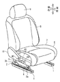
図1は、シート6の外観を示す。シート6は、座部を成すシートクッション7の後方に、背凭れを成すシートバック8が前後回動自在に固定されている。そのため、シートクッション7の後部とシートバック8の下部とのヒンジ部には、シートバック8のリクライニング角度を調整するためのリクライナ(図示略)が設けられている。 FIG. 1 shows the appearance of the sheet 6. In the seat 6, a seat back 8 forming a backrest is fixed to the rear of the seat cushion 7 forming the seat portion so as to be rotatable back and forth. Therefore, a reclining (not shown) for adjusting the reclining angle of the seat back 8 is provided at the hinge portion between the rear portion of the seat cushion 7 and the lower portion of the seat back 8.
シートバック8の上端部には、着座乗員の頭部を後方から支えるヘッドレスト9が設けられている。また、シートクッション7の右側部は、シートバック8の下部も含めてサイドシールド10により被われている。サイドシールド10内には、シート6に着座した乗員の好みに応じて着座姿勢を調整可能とするパワーシートの駆動装置40が収納されている。駆動装置40における操作部材を成す第1操作ノブ66及び第2操作ノブ67は、着座乗員による操作を可能とするようにサイドシールド10の外部に露出して配置されている。
A
シート6は、車両フロア(本発明の支持基盤に相当)に前後移動自在に固定されている。そのため、車両フロアには、シートクッション7の左右両側部の下方に一対のロアレール1が固定されている。そして、各ロアレール1には、アッパレール2がそれぞれ嵌め込まれて、ロアレール1に対して前後方向にスライド移動自在とされている。ロアレール1及びアッパレール2は、本発明におけるスライド部材に相当する。
The seat 6 is fixed to the vehicle floor (corresponding to the support base of the present invention) so as to be movable back and forth. Therefore, a pair of lower rails 1 are fixed below the left and right side portions of the seat cushion 7 on the vehicle floor. An
各アッパレール2の上には、ブラケット3a、3bがそれぞれ固定され、各ブラケット3a、3bの上にフロントリンク4及びリヤリンク5をそれぞれ介してシートクッション7が固定されている。フロントリンク4及びリヤリンク5は、ブラケット3a、3bに対して前後方向に傾動自在とされている。従って、後述するように、シート6は、フロントリンク4及びリヤリンク5の角度調整により車両フロアからの高さを調整可能とされている。
図2〜4は、駆動装置40と共にシート6の下部の骨格構造を示す。左右の各ロアレール1内には、スライド用ナット部材11が回転自在に固定されている。スライド用ナット部材11は、前後方向に貫通する雌ねじを備えている。一方、左右の各アッパレール2内には、アッパレール2の前後方向に沿って延びるスライド用リードスクリュ12(図6参照)が固定されている。スライド用リードスクリュ12の外周上には雄ねじが形成され、スライド用ナット部材11の雌ねじに螺合されている。図示を省略したが、各スライド用ナット部材11の外周側には、傘歯車が形成され、その傘歯車に噛み合う方向変換用の傘歯車が設けられている。方向変換用の各傘歯車は、少なくとも端部が多角柱形状とされたスライド用連結ロッド14の各端部に固定されて、互いに連結されている。
FIGS. 2-4 show the skeletal structure of the lower part of the seat 6 together with the
スライド用連結ロッド14の両端間部には、スライド用ギヤボックス13が結合されている。スライド用ギヤボックス13内には、互いに噛み合う傘歯車(図示略)を内蔵している。一方の傘歯車は、スライド用連結ロッド14と同期回転するように固定され、他方の傘歯車は、後述のスライド用トルクケーブル(本発明における動力伝達ケーブルに相当)16により回転されるように固定されている。
A
従って、モータ41の動力を受けてスライド用トルクケーブル16が回転すると、その回転が、スライド用ギヤボックス13を介してスライド用連結ロッド14に伝達される。そして、スライド用連結ロッド14の回転は、スライド用ナット部材11に伝達される。スライド用ナット部材11が回転されると、スライド用ナット部材11に螺合するスライド用リードスクリュ12によって前後進運動に変換されて、スライド用ナット部材11及びスライド用連結ロッド14が前後方向に移動される。ここで、スライド用ナット部材11、スライド用リードスクリュ12、スライド用ギヤボックス13、及びスライド用連結ロッド14は、ロアレール1及びアッパレール2と共にスライド用の位置調整機構としてのスライド調整機構Msを構成している。
Therefore, when the
各側のフロントリンク4は、各下端がブラケット3aに回動自在に固定され、各上端がシートクッション7の骨格部材を成すサイドフレーム20の前端部に回動自在に固定されている。また、各側のリヤリンク5は、各下端がブラケット3bに回動自在に固定され、各上端がサイドフレーム20の後端部に回動自在に固定されている。従って、アッパレール2、ブラケット3a、3b、フロントリンク4、リヤリンク5、及びサイドフレーム20は、4節リンクを構成している。
Each lower end of the
右側のリヤリンク5には、サイドフレーム20側の回転軸を中心に、その前側に略扇状に広がるセクタギヤ部5aが形成されている。具体的には、セクタギヤ部5aは、リヤリンク5に対して左右方向に分離され、回転軸で一体化されている。また、右側のリヤリンク5に隣接して、サイドフレーム20側面には、リフタ用ギヤボックス21が設けられている。リフタ用ギヤボックス21は、ウォーム(図示略)及びウォームホイール(図示略)を含む減速機構を内蔵している。ウォームホイールには、同軸でリフタ用ピニオン(図示略)が固定されている。リフタ用ピニオンは、セクタギヤ部5aと噛み合わされている。そして、ウォームは、リフタ用ギヤボックス21の前方に延在するリフタ用トルクケーブル(本発明における動力伝達ケーブルに相当)22の端部に固定されている。
The rear link 5 on the right side is formed with a
リフタ用トルクケーブル22が回転すると、その回転がウォームに伝達され、ウォームホイールで減速されてリフタ用ピニオンに伝達される。リフタ用ピニオンの回転は、セクタギヤ部5aを介してリヤリンク5に伝達されて、リヤリンク5が上端を中心に回転する。それにより、4節リンクを構成するフロントリンク4及びリヤリンク5が、ブラケット3a、3b側の固定点を中心に回転し、ブラケット3a、3bに対してサイドフレーム20を昇降する。ここで、フロントリンク4、リヤリンク5、及びリフタ用ギヤボックス21は、ブラケット3a、3b及びサイドフレーム20と共にリフタ用の位置調整機構としてのリフタ調整機構Mlを構成している。
When the
左右のサイドフレーム20の前後方向中央部より前側には、板材から成るチルトアーム25が、その後端部を中心に回動自在に固定されている。チルトアーム25の前端部には、チルトリンク(図示略)の上端が回動自在に固定され、チルトリンクの下端は、フロントリンク4の上端と同軸で回動自在に固定されている。
A
右側のチルトリンクには、その下端の回転軸を中心に、その前側に略扇状に広がるセクタギヤ部(図示略)が形成されている。また、右側のチルトリンクに隣接して、サイドフレーム20側面には、チルト用ギヤボックス27が設けられている。チルト用ギヤボックス27は、ウォーム(図示略)及びウォームホイール(図示略)を含む減速機構を内蔵している。ウォームホイールには、同軸でチルト用ピニオン(図示略)が固定されている。チルト用ピニオンは、セクタギヤ部と噛み合わされている。そして、ウォームは、チルト用ギヤボックス27の後方に延在するチルト用トルクケーブル(本発明における動力伝達ケーブルに相当)28の端部に固定されている。
The tilt link on the right side is formed with a sector gear portion (not shown) extending in a substantially fan shape on the front side of the rotation axis at the lower end thereof. A
チルト用トルクケーブル28が回転すると、その回転がウォームに伝達され、ウォームホイールで減速されてチルト用ピニオンに伝達される。チルト用ピニオンの回転は、セクタギヤ部を介してチルトリンクに伝達されて、チルトリンクが下端を中心に回動する。それにより、チルトアーム25が、その後端部を中心に回動し、その前端部を昇降する。そのため、サイドフレーム20に対するチルトアーム25の傾斜角度が増減する。ここで、チルトリンク、及びチルト用ギヤボックス27は、チルトアーム25及びサイドフレーム20と共にチルト用の位置調整機構としてのチルト調整機構Mtを構成している。
When the
各側のサイドフレーム20の後端部には、板材から成るリクライナプレート31が固定されている。リクライナプレート31には、略円盤状のリクライナ32を介してシートバック8の下端部が結合されている。このリクライナ32は、周知のハイポサイクロイド減速機を構成するものである。即ち、リクライナ32は、図示を省略したが、内歯歯車を有してリクライナプレート31に固定される第1ディスクと、内歯歯車の歯数よりも少ない歯数でこれに噛合する外歯歯車を有する第2ディスクと、内歯歯車及び外歯歯車を噛合すべくこれらの偏心状態を保つ楔部材と、第1ディスク(内歯歯車)と同軸に配置されて第2ディスクが軸支され楔部材を移動させるカム軸等とを備えて構成される。そして、リクライナ32は、第2ディスクにおいてシートバック8に固定されている。リクライナ32は、カム軸の回転に伴う楔部材の移動により、内歯歯車及び外歯歯車の噛合状態を保ったまま第2ディスクを公転させることで、この公転時における第2ディスクの自転数としてカム軸の回転を減速する。そして、第1ディスクに対する第2ディスクの回転により、シートクッション7に対してシートバック8が回動(傾動)する。
A
右側のリクライナプレート31には、その外側にリクライナ用ギヤボックス33が固定されている。このリクライナ用ギヤボックス33は、ウォーム(図示略)及びウォームホイール(図示略)から成る減速機構を内蔵する。ウォームホイールは、シート幅方向に延びる軸線を有して両側のリクライナ32間に橋渡しされる多角柱状のリクライナ用連結ロッド34に一体回転するように連結されている。このリクライナ用連結ロッド34は、両側のリクライナ32を貫通してそれらのカム軸に一体回転するように連結されている。一方、ウォームは、リクライナ用ギヤボックス33の前方に延在するリクライナ用トルクケーブル(本発明における動力伝達ケーブルに相当)35の端部に固定されている。
A reclining
従って、リクライナ用トルクケーブル35が回転すると、その回転がリクライナ用ギヤボックス33の入力側であるウォーム及び出力側であるウォームホイール間で減速されてリクライナ用連結ロッド34に伝達される。そして、リクライナ用連結ロッド34の回転は、リクライナ32のカム軸に伝達される。これにより、前述の態様でリクライナ32の第1ディスクに対して第2ディスクが回転し、シートクッション7に対してシートバック8が回動(傾動)する。ここで、リクライナ32、リクライナ用ギヤボックス33及びリクライナ用連結ロッド34は、リクライナプレート31及びシートバック8とともにリクライナ用の位置調整機構としてのリクライニング角度調整機構Mrを構成する。
Therefore, when the
以上のように、本実施形態は、スライド調整機構Ms、リフタ調整機構Ml、チルト調整機構Mt及びリクライニング角度調整機構Mrの各々において正方向及び逆方向にシート位置の調整が可能な、いわゆる8ウェイパワーシートとなっている。これらの各調整機構Ms、Ml、Mt、Mrは、本発明における調整機構に相当する。 As described above, in the present embodiment, the so-called 8-way seat position can be adjusted in the forward direction and the reverse direction in each of the slide adjustment mechanism Ms, the lifter adjustment mechanism Ml, the tilt adjustment mechanism Mt, and the reclining angle adjustment mechanism Mr. It is a power seat. Each of these adjusting mechanisms Ms, Ml, Mt, and Mr corresponds to the adjusting mechanism in the present invention.
右側のサイドフレーム20のリフタ用ギヤボックス21及びチルト用ギヤボックス27間に挟まれる前後方向中間部には、駆動装置40が固定されている。駆動装置40は、単一の出力軸を有するモータ41を備える。そのモータ41の出力軸は、後述のようにクラッチ機構を介して、スライド用トルクケーブル16、リフタ用トルクケーブル22、チルト用トルクケーブル28及びリクライナ用トルクケーブル35に接続している。従って、一つのモータ41によりスライド調整機構Ms、リフタ調整機構Ml、チルト調整機構Mt及びリクライニング角度調整機構Mrを調整動作可能としている。
The
図5は、駆動装置40の詳細を示す。駆動装置40は、駆動機構部分と操作機構部分とから成るが、ここでは、駆動機構部分のみを示し、操作機構部分の図示は省略している。なお、操作機構部分は、第1操作ノブ66及び第2操作ノブ67の操作に応じて、モータ41の駆動回路(図示略)に挿入接続されたスイッチ(図示略)をオンオフ操作する機構、並びに後述のように駆動機構部分にある各クラッチ機構を接続、非接続に切り替え操作する機構を備える。
FIG. 5 shows the details of the
駆動機構部分は、単一のモータ41を備え、モータ41は、単一のモータ出力軸42を備える。モータ出力軸42には、ウォーム43が結合され、ウォーム43には、上下に分散する一対のウォームホイール44、45が噛み合わされている。従って、ウォーム43とウォームホイール44、45の組み合わせによって、モータ41からの一軸の回転出力が二軸の回転出力に変換されている。
The drive mechanism portion comprises a
ウォームホイール44、45の各回転軸の前後方向両側には、それぞれクラッチ機構が結合されている。即ち、ウォームホイール44の回転軸の前側の入力軸44aには、チルト用クラッチ機構46Tが結合され、後側の入力軸44bには、リクライナ用クラッチ機構46Rが結合されている。また、ウォームホイール45の回転軸の前側の入力軸45aには、スライド用クラッチ機構46Sが結合され、後側の入力軸45bには、リフタ用クラッチ機構46Lが結合されている。
Clutch mechanisms are coupled to both sides of the rotation shafts of the
チルト用クラッチ機構46Tの出力軸47Tには、ハスバ歯車48Tが結合され、ハスバ歯車48Tには、その回転軸に対して交差方向に回転軸を配置されたハスバ歯車49Tが噛合されている。両ハスバ歯車48T、49Tの組み合わせによって、チルト用クラッチ機構46Tの出力軸47Tの軸方向が変換されている。
A
更に、スライド用クラッチ機構46Sの出力軸47Sには、ハスバ歯車48Sが結合され、ハスバ歯車48Sには、その回転軸に対して交差方向に回転軸を配置されたハスバ歯車49Sが噛合されている。ハスバ歯車48S、49Sの組み合わせによって、スライド用クラッチ機構46Sの出力軸47Sの軸方向が変換されている。なお、リクライナ用クラッチ機構46Rの出力軸47R、並びにリフタ用クラッチ機構46Lの出力軸47Lは、軸方向が変換されていない。
Further, the
図5では、チルト用クラッチ機構46Tにおいて入力軸44aと出力軸47Tとが接続された状態を示している。また、リクライナ用クラッチ機構46R、スライド用クラッチ機構46S及びリフタ用クラッチ機構46Lにおいては、各入力軸44b、45a、45bと出力軸47R、47S、47Lとが非接続とされた状態を示している。この状態では、モータ41の回転は、チルト用クラッチ機構46Tを介してチルト調整機構Mtに伝達されている。この状態からチルト用クラッチ機構46Tが非接続状態とされ、リクライナ用クラッチ機構46R、スライド用クラッチ機構46S及びリフタ用クラッチ機構46Lのいずれかが接続状態とされると、接続状態とされたクラッチ機構に対応した調整機構にモータ41の回転が伝達される。
FIG. 5 shows a state in which the
駆動装置40の駆動機構部分を構成するモータ41、各クラッチ機構46S、46T、46L、46R等の各部材は、ギヤケース半体50a内に収納されている。ギヤケース半体50aには、組み合わせることにより一つの函体であるギヤケース50を成すギヤケース半体50b(図2参照)が被せられている。
Members such as the
駆動装置40の操作機構部分は、ギヤケース50の右側に、各クラッチ機構46S、46T、46L、46Rを個々に駆動する各クラッチ駆動手段(図示略)、また、モータ41の作動回路に接続されたスイッチ及びそのスイッチを操作するスイッチ操作手段(図示略)等が配置されて操作機構カバー65が被せられている(図1参照)。更に、操作機構カバー65の右側には、第1操作ノブ66及び第2操作ノブ67が配置されている。
The operation mechanism portion of the
以上のパワーシートでは、第1操作ノブ66及び第2操作ノブ67の操作により選択された各調整機構Ms、Ml、Mt、Mrに対応した各クラッチ機構46S、46T、46L、46Rのいずれかが接続されて、モータ41の出力が各トルクケーブル16、22、28、35を介していずれかの調整機構Ms、Ml、Mt、Mrに伝達される。その結果、一つのモータ41により各調整機構Ms、Ml、Mt、Mrのいずれかが作動される。
In the above power seat, any of the
モータ41及び駆動装置40は、サイドフレーム20に固定されている。また、リフタ調整機構Ml、チルト調整機構Mt及びリクライニング角度調整機構Mrもサイドフレーム20に対して相対移動しないように固定されている。一方、スライド調整機構Msは、サイドフレーム20から離れたアッパレール2に固定されている。そのため、リフタ調整機構Mlによりシート6の高さ調整が行われると、図6に示すスライド用トルクケーブル16の一端のモータ側接続部であるケーブルコネクタ51と、他端のスライド調整機構Ms側接続部であるケーブルコネクタ13aとの相対位置が上下方向に変化することになる。図6は、シート6の高さが最も低くされた状態を示す。この状態では、ケーブルコネクタ51、13a間の距離が最も短くなる。一方、図7は、シート6の高さが最も高くされた状態を示す。この状態では、ケーブルコネクタ51、13a間の距離が最も長くなる。なお、モータ41を固定するサイドフレーム20及びスライド調整機構Msを固定するアッパレール2は、本発明の各部材に相当する。
The
スライド用トルクケーブル16において、アウタケーブル16aは、ケーブルコネクタ13aに対しては相対移動しないように固定されているが、ケーブルコネクタ51に対してはスライド用トルクケーブル16の軸方向に摺動自在(移動可能)に固定されている。また、インナケーブル16bは、ハスバ歯車13bに対しては、その回転中心で相対移動しないように固定されているが、ハスバ歯車49Sに対しては、その回転中心でスライド用トルクケーブル16の軸方向に摺動自在(移動可能)に固定されている。ケーブルコネクタ13aは、本発明における「調整機構の入力軸の軸受側部材」に相当し、ケーブルコネクタ51は、本発明における「モータの出力軸の軸受側部材」に相当する。また、ハスバ歯車13bは、本発明における調整機構の入力軸に相当し、前段ギヤに相当する。ハスバ歯車13bに噛み合いスライド用連結ロッド14と同軸結合されたハスバ歯車(図示略)は、本発明における後段ギヤに相当する。また、ハスバ歯車49Sは、本発明におけるモータの出力軸に相当し、後段ギヤに相当する。ハスバ歯車48Sは、本発明における前段ギヤに相当する。
In the
そのため、図6のようにケーブルコネクタ51、13a間の距離が最も短くなる状態では、アウタケーブル16aはケーブルコネクタ51に対して最も深く挿入された状態となり、インナケーブル16bはハスバ歯車49Sの回転軸を貫通してハスバ歯車49Sの外部に突出した状態となる。一方、図7のようにケーブルコネクタ51、13a間の距離が最も長くなる状態では、アウタケーブル16aはケーブルコネクタ51に対する挿入量が少なくされた状態となり、インナケーブル16bはハスバ歯車49Sの回転軸に対する挿入量が少なくされた状態となる。このとき、図6におけるスライド用トルクケーブル16のアウタケーブル16a及びインナケーブル16bのケーブルコネクタ51及びハスバ歯車49Sの位置に対し、図7におけるスライド用トルクケーブル16のアウタケーブル16a及びインナケーブル16bの位置は、図7に「L」で示す寸法だけハスバ歯車49Sの回転軸方向に移動している。
Therefore, when the distance between the
図7のように、ハスバ歯車49Sの回転軸に対するインナケーブル16bの挿入量が少なくされた状態において、インナケーブル16bはハスバ歯車49Sのギヤ部に対応する位置まで挿入されている。そのため、インナケーブル16bの回転トルクをハスバ歯車49Sに確実に伝達することができる。
As shown in FIG. 7, the
一方、図6のように、インナケーブル16bはハスバ歯車49Sの回転軸を貫通してハスバ歯車49Sの外部に突出される。ハスバ歯車49Sは方向変換ギヤであり、ハスバ歯車49Sに噛み合うハスバ歯車48Sは、ハスバ歯車49Sに対して回転軸方向がずれている。そのため、インナケーブル16bは他の部材の制約を受けることなく外部に突出することができ、インナケーブル16bの余長を充分に吸収することができる。
On the other hand, as shown in FIG. 6, the
このように本実施形態では、リフタ調整機構Mlによるシート6の高さ調整に伴うスライド用トルクケーブル16のケーブルコネクタ51、13a間の距離の変化を、アウタケーブル16a及びインナケーブル16bのケーブルコネクタ51及びハスバ歯車49Sに対する移動により吸収している。そのため、図8に基づいて説明した従来のようなスライド用トルクケーブル16の湾曲度合の変化は抑制される。
As described above, in the present embodiment, the change in the distance between the
上記実施形態では、スライド用トルクケーブル16のケーブルコネクタ13a側を相対移動しないように固定し、ケーブルコネクタ51側を摺動自在に固定したが、反対にケーブルコネクタ13a側を摺動自在(移動可能)にし、ケーブルコネクタ51側を相対移動しないように固定してもよい。
In the above embodiment, the
以上、特定の実施形態について説明したが、本発明は、それらの外観、構成に限定されず、本発明の要旨を変更しない範囲で種々の変更、追加、削除が可能である。例えば、上記実施形態では、本発明を車両のシートに適用したが、飛行機、船、電車等に搭載のシート、若しくは映画館で使用されるシートに適用しても良い。 Although the specific embodiments have been described above, the present invention is not limited to their appearance and configuration, and various changes, additions, and deletions can be made without changing the gist of the present invention. For example, in the above embodiment, the present invention is applied to a vehicle seat, but it may be applied to a seat mounted on an airplane, a ship, a train, or the like, or a seat used in a movie theater.
上記実施形態では、モータに対して動力伝達ケーブルを介して接続され、モータに対して固定位置が相対移動する第1の調整機構をスライド調整機構とし、その相対移動を起こさせる第2の調整機構をリフタ調整機構とし、両機構は、一つのモータにより作動されるものとした。この実施形態は、本発明の第1発明において説明した第3の構成に相当する。 In the above embodiment, a first adjusting mechanism that is connected to the motor via a power transmission cable and whose fixed position moves relative to the motor is used as a slide adjusting mechanism, and a second adjusting mechanism that causes the relative movement. Was used as the lifter adjustment mechanism, and both mechanisms were operated by one motor. This embodiment corresponds to the third configuration described in the first invention of the present invention.
これに対する別の実施形態として、両機構を作動させるモータを互いに独立して設けるものとしてもよい。また、別の実施形態として、第2の調整機構であるリフタ調整機構が手動により作動されるものとしてもよい。これらの別の実施形態は、本発明の第1発明において説明した第2の構成に相当する。 As another embodiment, motors for operating both mechanisms may be provided independently of each other. Further, as another embodiment, the lifter adjusting mechanism, which is the second adjusting mechanism, may be manually operated. These other embodiments correspond to the second configuration described in the first invention of the present invention.
更に別の実施形態として、動力伝達ケーブルを介してモータにより作動される調整機構をシートバックの中折れ調整機構としてもよい。なお、中折れ調整機構は、シートバックが上下方向の間で前後方向に折れ曲がるように構成され、その折れ曲がり角度が調整可能とされたものである。この場合、モータと中折れ調整機構との相対位置は、自らの調整作動により変化される。この別の実施形態は、本発明の第1発明において説明した第1の構成に相当する。 As yet another embodiment, the adjusting mechanism operated by the motor via the power transmission cable may be used as the seat back center bending adjusting mechanism. The center bending adjustment mechanism is configured so that the seat back bends in the front-rear direction between the vertical directions, and the bending angle can be adjusted. In this case, the relative position between the motor and the center bending adjustment mechanism is changed by its own adjustment operation. This other embodiment corresponds to the first configuration described in the first invention of the present invention.
Ms スライド調整機構(調整機構、第1の調整機構)
Ml リフタ調整機構(調整機構、第2の調整機構)
Mt チルト調整機構(調整機構)
Mr リクライニング角度調整機構(調整機構)
1 ロアレール(スライド部材)
2 アッパレール(スライド部材)
3a、3b ブラケット
4 フロントリンク
5 リヤリンク
6 車両用フロントシート(シート)
7 シートクッション
8 シートバック
9 ヘッドレスト
10 サイドシールド
11 スライド用ナット部材
12 スライド用リードスクリュ
13 スライド用ギヤボックス
13a ケーブルコネクタ(軸受側部材)
13b ハスバ歯車(前段ギヤ)
14 スライド用連結ロッド
16 スライド用トルクケーブル(動力伝達ケーブル)
16a アウタケーブル
16b インナケーブル
20 サイドフレーム(骨格部材)
21 リフタ用ギヤボックス
22 リフタ用トルクケーブル(動力伝達ケーブル)
25 チルトアーム
27 チルト用ギヤボックス
28 チルト用トルクケーブル(動力伝達ケーブル)
31 リクライナプレート
32 リクライナ
33 リクライナ用ギヤボックス
34 リクライナ用連結ロッド
35 リクライナ用トルクケーブル(動力伝達ケーブル)
40 駆動装置
41 モータ
42 モータ出力軸
43 ウォーム
44、45 ウォームホイール
44a、44b、45a、45b 入力軸
46S スライド用クラッチ機構
46T チルト用クラッチ機構
46L リフタ用クラッチ機構
46R リクライナ用クラッチ機構
47S、47T、47L、47R 出力軸
48S ハスバ歯車(前段ギヤ)
49S ハスバ歯車(後段ギヤ)
48T、49T ハスバ歯車
50 ギヤケース
50a、50b ギヤケース半体
51 ケーブルコネクタ(軸受側部材)
65 操作機構カバー
66 第1操作ノブ
67 第2操作ノブ
Ms slide adjustment mechanism (adjustment mechanism, first adjustment mechanism)
Ml lifter adjustment mechanism (adjustment mechanism, second adjustment mechanism)
Mt tilt adjustment mechanism (adjustment mechanism)
Mr reclining angle adjustment mechanism (adjustment mechanism)
1 Lower rail (slide member)
2 Upper rail (slide member)
3a,
7
13b Hasuba gear (front gear)
14
21 Gear box for
25
31
40
49S Hasuba gear (rear gear)
48T,
65 Operation mechanism cover 66
Claims (6)
前記動力伝達ケーブルは、アウタケーブル内でインナケーブルが回転自在に構成されており、
前記動力伝達ケーブルのアウタケーブルは、一端が前記モータの出力軸の軸受側部材に接続され、また他端が前記調整機構の入力軸の軸受側部材に接続されており、
前記動力伝達ケーブルのインナケーブルは、一端が前記モータの出力軸に接続され、また他端が前記調整機構の入力軸に接続されており、
前記アウタケーブルの一端若しくは他端は、前記モータの出力軸の軸受側部材若しくは前記調整機構の入力軸の軸受側部材に対して軸方向に移動可能に接続されており、
前記インナケーブルの一端若しくは他端は、前記モータの出力軸若しくは前記調整機構の入力軸に対して軸方向に移動可能に接続されているパワーシートの動力伝達装置。 A power transmission device for a power seat in which the power of the motor is transmitted to the adjustment mechanism of the power seat via a power transmission cable to operate the adjustment mechanism, and the motor and the adjustment mechanism are fixed to separate members that move relative to each other. In
In the power transmission cable, the inner cable is rotatably configured in the outer cable.
One end of the outer cable of the power transmission cable is connected to the bearing side member of the output shaft of the motor, and the other end is connected to the bearing side member of the input shaft of the adjustment mechanism.
One end of the inner cable of the power transmission cable is connected to the output shaft of the motor, and the other end is connected to the input shaft of the adjustment mechanism.
One end or the other end of the outer cable is axially movably connected to a bearing side member of the output shaft of the motor or a bearing side member of the input shaft of the adjustment mechanism.
One end or the other end of the inner cable is a power transmission device for a power seat that is axially movably connected to the output shaft of the motor or the input shaft of the adjustment mechanism.
前記モータ及び前記調整機構を固定する前記各部材は、前記調整機構を第1の調整機構としたとき、該第1の調整機構とは独立した第2の調整機構によって前記各部材が相対移動されるパワーシートの動力伝達装置。 In claim 1,
When the adjusting mechanism is used as the first adjusting mechanism, the motor and the respective members fixing the adjusting mechanism are relatively moved by a second adjusting mechanism independent of the first adjusting mechanism. Power transmission device for power seats.
前記調整機構を複数個備え、それらの調整機構は前記モータの動力をそれぞれ各動力伝達ケーブルを介して伝達されており、
前記複数の調整機構のうちの一つである第1の調整機構は、前記複数の調整機構のうちの他の一つである第2の調整機構によって前記モータ及び前記第1の調整機構を固定する前記各部材が相対移動されるパワーシートの動力伝達装置。 In claim 1 or 2,
A plurality of the adjusting mechanisms are provided, and the power of the motor is transmitted to each of the adjusting mechanisms via each power transmission cable.
The first adjusting mechanism, which is one of the plurality of adjusting mechanisms, fixes the motor and the first adjusting mechanism by the second adjusting mechanism, which is the other one of the plurality of adjusting mechanisms. A power transmission device for a power seat in which the respective members are relatively moved.
前記第1の調整機構は、骨格部材を含むシートの支持基盤に沿った方向位置を調整するスライド部材に固定されたスライド調整機構であり、
前記第2の調整機構は、前記スライド部材上における前記骨格部材を含むシートの高さを調整する上下高さ調整機構であり、
前記モータは前記骨格部材に固定されているパワーシートの動力伝達装置。 In claim 2 or 3,
The first adjusting mechanism is a slide adjusting mechanism fixed to a slide member that adjusts a directional position along a support base of a sheet including a skeleton member.
The second adjusting mechanism is a vertical height adjusting mechanism that adjusts the height of the sheet including the skeleton member on the slide member.
The motor is a power transmission device for a power seat fixed to the skeleton member.
前記モータの出力軸又は前記調整機構の入力軸には、互いに連結され、且つ互いの回転軸方向をずらされた前段ギヤ及び後段ギヤを備え、
前記インナケーブルの一端又は他端は、前記モータの出力軸の後段ギヤ又は前記調整機構の入力軸の前段ギヤの回転軸を貫通し、回転軸方向に摺動自在で回転方向に結合されているパワーシートの動力伝達装置。 In any of claims 1 to 4,
The output shaft of the motor or the input shaft of the adjustment mechanism is provided with front gears and rear gears that are connected to each other and whose rotation axis directions are deviated from each other.
One end or the other end of the inner cable penetrates the rotation shaft of the rear gear of the output shaft of the motor or the front gear of the input shaft of the adjustment mechanism, and is slidable in the rotation shaft direction and coupled in the rotation direction. Power transmission device for power seats.
前記インナケーブルの一端又は他端は、前記モータと前記調整機構との相対距離が最長となる状態で、前記モータの出力軸の後段ギヤ又は前記調整機構の入力軸の前段ギヤの回転軸方向で前記後段ギヤ又は前記前段ギヤのギヤ部に対応する位置にあり、前記モータと前記調整機構との相対距離が最短となる状態では、前記インナケーブルの先端が前記後段ギヤ又は前記前段ギヤの回転軸を貫通して前記各ギヤから突出するように構成されているパワーシートの動力伝達装置。
In claim 5,
One end or the other end of the inner cable is in the direction of the rotation axis of the rear gear of the output shaft of the motor or the front gear of the input shaft of the adjustment mechanism in a state where the relative distance between the motor and the adjustment mechanism is the longest. When the position corresponds to the rear gear or the gear portion of the front gear and the relative distance between the motor and the adjustment mechanism is the shortest, the tip of the inner cable is the rotation shaft of the rear gear or the front gear. A power transmission device for a power seat configured to penetrate and project from each of the gears.
Priority Applications (4)
| Application Number | Priority Date | Filing Date | Title |
|---|---|---|---|
| JP2017003215A JP6769309B2 (en) | 2017-01-12 | 2017-01-12 | Power seat power transmission |
| US15/863,213 US10647223B2 (en) | 2017-01-12 | 2018-01-05 | Power transmission device for power seat |
| DE102018200142.1A DE102018200142B4 (en) | 2017-01-12 | 2018-01-08 | Power transmission device for a motorized seat |
| CN201820051701.1U CN207972552U (en) | 2017-01-12 | 2018-01-12 | Power transmission device for automatic seat |
Applications Claiming Priority (1)
| Application Number | Priority Date | Filing Date | Title |
|---|---|---|---|
| JP2017003215A JP6769309B2 (en) | 2017-01-12 | 2017-01-12 | Power seat power transmission |
Publications (2)
| Publication Number | Publication Date |
|---|---|
| JP2018111413A JP2018111413A (en) | 2018-07-19 |
| JP6769309B2 true JP6769309B2 (en) | 2020-10-14 |
Family
ID=62636645
Family Applications (1)
| Application Number | Title | Priority Date | Filing Date |
|---|---|---|---|
| JP2017003215A Active JP6769309B2 (en) | 2017-01-12 | 2017-01-12 | Power seat power transmission |
Country Status (4)
| Country | Link |
|---|---|
| US (1) | US10647223B2 (en) |
| JP (1) | JP6769309B2 (en) |
| CN (1) | CN207972552U (en) |
| DE (1) | DE102018200142B4 (en) |
Families Citing this family (6)
| Publication number | Priority date | Publication date | Assignee | Title |
|---|---|---|---|---|
| EP3122592B1 (en) * | 2014-03-25 | 2020-07-15 | CVG Management Corporation | Seat tilt control mechanism |
| DE102016224512A1 (en) * | 2016-12-08 | 2018-06-14 | Brose Fahrzeugteile Gmbh & Co. Kg, Coburg | Vehicle seat assembly with a floor rail side arranged drive means |
| JP6753320B2 (en) * | 2017-01-19 | 2020-09-09 | トヨタ紡織株式会社 | Seat drive |
| JP7079403B2 (en) * | 2017-10-20 | 2022-06-02 | テイ・エス テック株式会社 | Vehicle seat |
| DE102019122310B4 (en) | 2019-04-08 | 2022-06-23 | Adient Us Llc | VEHICLE SEAT |
| WO2021163659A1 (en) * | 2020-02-14 | 2021-08-19 | Magna Seating Inc. | Seat assembly with power easy entry having concentric motion |
Family Cites Families (6)
| Publication number | Priority date | Publication date | Assignee | Title |
|---|---|---|---|---|
| DE8706591U1 (en) | 1987-05-07 | 1987-06-25 | Brose Fahrzeugteile Gmbh & Co Kg, 8630 Coburg, De | |
| DE10057476B4 (en) | 2000-11-20 | 2007-10-31 | Siemens Ag | Flexible element |
| JP4000858B2 (en) * | 2002-02-06 | 2007-10-31 | アイシン精機株式会社 | Power slide device for seat |
| JP4419518B2 (en) * | 2003-10-30 | 2010-02-24 | アイシン精機株式会社 | Seat slide device |
| DE102009008501B4 (en) | 2009-02-06 | 2012-09-13 | Keiper Gmbh & Co. Kg | safety device |
| JP5692536B2 (en) | 2011-10-24 | 2015-04-01 | アイシン精機株式会社 | Sheet drive device |
-
2017
- 2017-01-12 JP JP2017003215A patent/JP6769309B2/en active Active
-
2018
- 2018-01-05 US US15/863,213 patent/US10647223B2/en active Active
- 2018-01-08 DE DE102018200142.1A patent/DE102018200142B4/en active Active
- 2018-01-12 CN CN201820051701.1U patent/CN207972552U/en active Active
Also Published As
| Publication number | Publication date |
|---|---|
| DE102018200142B4 (en) | 2021-09-02 |
| US10647223B2 (en) | 2020-05-12 |
| CN207972552U (en) | 2018-10-16 |
| US20180194250A1 (en) | 2018-07-12 |
| JP2018111413A (en) | 2018-07-19 |
| DE102018200142A1 (en) | 2018-07-12 |
Similar Documents
| Publication | Publication Date | Title |
|---|---|---|
| JP6769309B2 (en) | Power seat power transmission | |
| JP5286861B2 (en) | Motion conversion drive device and vehicle seat device including the motion conversion drive device | |
| EP2208632B1 (en) | Vehicle seat device | |
| JP5239380B2 (en) | Vehicle seat | |
| JP7004271B2 (en) | Vehicle seat | |
| JP6962845B2 (en) | Vehicle seat | |
| JP6753320B2 (en) | Seat drive | |
| JP2023075318A (en) | vehicle seat | |
| JP2008105520A (en) | Driving mechanism of vehicular power seat | |
| US10682926B2 (en) | Seat drive device | |
| JP6289871B2 (en) | Automotive seat height adjustment device | |
| JP6773965B2 (en) | Vehicle seat | |
| JP6219738B2 (en) | Headrest device | |
| KR20120136556A (en) | Leg rest apparatus for vehicle seat | |
| JP6518546B2 (en) | Seat lifter | |
| JP2018184019A (en) | Sheet drive device | |
| JP6926915B2 (en) | Power seat | |
| JP6874616B2 (en) | Power seat power transmission device | |
| JP2009100884A (en) | Rear seat device | |
| JP6753245B2 (en) | Seat drive | |
| CN108602455A (en) | The backrest pivoted with power shoulder | |
| JP6701962B2 (en) | Vehicle seat | |
| JP6888513B2 (en) | Power seat power transmission device | |
| KR101232079B1 (en) | Leg rest apparatus for vehicle seat | |
| JP7188286B2 (en) | Vehicle seat device |
Legal Events
| Date | Code | Title | Description |
|---|---|---|---|
| A621 | Written request for application examination |
Free format text: JAPANESE INTERMEDIATE CODE: A621 Effective date: 20190923 |
|
| A977 | Report on retrieval |
Free format text: JAPANESE INTERMEDIATE CODE: A971007 Effective date: 20200817 |
|
| TRDD | Decision of grant or rejection written | ||
| A01 | Written decision to grant a patent or to grant a registration (utility model) |
Free format text: JAPANESE INTERMEDIATE CODE: A01 Effective date: 20200825 |
|
| A61 | First payment of annual fees (during grant procedure) |
Free format text: JAPANESE INTERMEDIATE CODE: A61 Effective date: 20200907 |
|
| R151 | Written notification of patent or utility model registration |
Ref document number: 6769309 Country of ref document: JP Free format text: JAPANESE INTERMEDIATE CODE: R151 |
|
| R250 | Receipt of annual fees |
Free format text: JAPANESE INTERMEDIATE CODE: R250 |