KR20200021549A - Phosphorescent materials - Google Patents
Phosphorescent materials Download PDFInfo
- Publication number
- KR20200021549A KR20200021549A KR1020207004780A KR20207004780A KR20200021549A KR 20200021549 A KR20200021549 A KR 20200021549A KR 1020207004780 A KR1020207004780 A KR 1020207004780A KR 20207004780 A KR20207004780 A KR 20207004780A KR 20200021549 A KR20200021549 A KR 20200021549A
- Authority
- KR
- South Korea
- Prior art keywords
- compound
- compounds
- mmol
- mixture
- ring
- Prior art date
Links
Images


Classifications
-
- C—CHEMISTRY; METALLURGY
- C07—ORGANIC CHEMISTRY
- C07F—ACYCLIC, CARBOCYCLIC OR HETEROCYCLIC COMPOUNDS CONTAINING ELEMENTS OTHER THAN CARBON, HYDROGEN, HALOGEN, OXYGEN, NITROGEN, SULFUR, SELENIUM OR TELLURIUM
- C07F15/00—Compounds containing elements of Groups 8, 9, 10 or 18 of the Periodic System
- C07F15/0006—Compounds containing elements of Groups 8, 9, 10 or 18 of the Periodic System compounds of the platinum group
- C07F15/0033—Iridium compounds
-
- C—CHEMISTRY; METALLURGY
- C09—DYES; PAINTS; POLISHES; NATURAL RESINS; ADHESIVES; COMPOSITIONS NOT OTHERWISE PROVIDED FOR; APPLICATIONS OF MATERIALS NOT OTHERWISE PROVIDED FOR
- C09K—MATERIALS FOR MISCELLANEOUS APPLICATIONS, NOT PROVIDED FOR ELSEWHERE
- C09K11/00—Luminescent, e.g. electroluminescent, chemiluminescent materials
- C09K11/06—Luminescent, e.g. electroluminescent, chemiluminescent materials containing organic luminescent materials
-
- H01L51/0054—
-
- H01L51/006—
-
- H01L51/0074—
-
- H01L51/0081—
-
- H01L51/0085—
-
- H01L51/5016—
-
- H01L51/5024—
-
- H—ELECTRICITY
- H05—ELECTRIC TECHNIQUES NOT OTHERWISE PROVIDED FOR
- H05B—ELECTRIC HEATING; ELECTRIC LIGHT SOURCES NOT OTHERWISE PROVIDED FOR; CIRCUIT ARRANGEMENTS FOR ELECTRIC LIGHT SOURCES, IN GENERAL
- H05B33/00—Electroluminescent light sources
- H05B33/12—Light sources with substantially two-dimensional radiating surfaces
- H05B33/14—Light sources with substantially two-dimensional radiating surfaces characterised by the chemical or physical composition or the arrangement of the electroluminescent material, or by the simultaneous addition of the electroluminescent material in or onto the light source
-
- H—ELECTRICITY
- H10—SEMICONDUCTOR DEVICES; ELECTRIC SOLID-STATE DEVICES NOT OTHERWISE PROVIDED FOR
- H10K—ORGANIC ELECTRIC SOLID-STATE DEVICES
- H10K50/00—Organic light-emitting devices
- H10K50/10—OLEDs or polymer light-emitting diodes [PLED]
- H10K50/11—OLEDs or polymer light-emitting diodes [PLED] characterised by the electroluminescent [EL] layers
- H10K50/12—OLEDs or polymer light-emitting diodes [PLED] characterised by the electroluminescent [EL] layers comprising dopants
-
- H—ELECTRICITY
- H10—SEMICONDUCTOR DEVICES; ELECTRIC SOLID-STATE DEVICES NOT OTHERWISE PROVIDED FOR
- H10K—ORGANIC ELECTRIC SOLID-STATE DEVICES
- H10K85/00—Organic materials used in the body or electrodes of devices covered by this subclass
- H10K85/30—Coordination compounds
- H10K85/341—Transition metal complexes, e.g. Ru(II)polypyridine complexes
- H10K85/342—Transition metal complexes, e.g. Ru(II)polypyridine complexes comprising iridium
-
- C—CHEMISTRY; METALLURGY
- C09—DYES; PAINTS; POLISHES; NATURAL RESINS; ADHESIVES; COMPOSITIONS NOT OTHERWISE PROVIDED FOR; APPLICATIONS OF MATERIALS NOT OTHERWISE PROVIDED FOR
- C09K—MATERIALS FOR MISCELLANEOUS APPLICATIONS, NOT PROVIDED FOR ELSEWHERE
- C09K2211/00—Chemical nature of organic luminescent or tenebrescent compounds
- C09K2211/10—Non-macromolecular compounds
- C09K2211/1003—Carbocyclic compounds
- C09K2211/1007—Non-condensed systems
-
- C—CHEMISTRY; METALLURGY
- C09—DYES; PAINTS; POLISHES; NATURAL RESINS; ADHESIVES; COMPOSITIONS NOT OTHERWISE PROVIDED FOR; APPLICATIONS OF MATERIALS NOT OTHERWISE PROVIDED FOR
- C09K—MATERIALS FOR MISCELLANEOUS APPLICATIONS, NOT PROVIDED FOR ELSEWHERE
- C09K2211/00—Chemical nature of organic luminescent or tenebrescent compounds
- C09K2211/10—Non-macromolecular compounds
- C09K2211/1003—Carbocyclic compounds
- C09K2211/1011—Condensed systems
-
- C—CHEMISTRY; METALLURGY
- C09—DYES; PAINTS; POLISHES; NATURAL RESINS; ADHESIVES; COMPOSITIONS NOT OTHERWISE PROVIDED FOR; APPLICATIONS OF MATERIALS NOT OTHERWISE PROVIDED FOR
- C09K—MATERIALS FOR MISCELLANEOUS APPLICATIONS, NOT PROVIDED FOR ELSEWHERE
- C09K2211/00—Chemical nature of organic luminescent or tenebrescent compounds
- C09K2211/10—Non-macromolecular compounds
- C09K2211/1018—Heterocyclic compounds
- C09K2211/1025—Heterocyclic compounds characterised by ligands
- C09K2211/1059—Heterocyclic compounds characterised by ligands containing three nitrogen atoms as heteroatoms
- C09K2211/1066—Heterocyclic compounds characterised by ligands containing three nitrogen atoms as heteroatoms with sulfur
-
- C—CHEMISTRY; METALLURGY
- C09—DYES; PAINTS; POLISHES; NATURAL RESINS; ADHESIVES; COMPOSITIONS NOT OTHERWISE PROVIDED FOR; APPLICATIONS OF MATERIALS NOT OTHERWISE PROVIDED FOR
- C09K—MATERIALS FOR MISCELLANEOUS APPLICATIONS, NOT PROVIDED FOR ELSEWHERE
- C09K2211/00—Chemical nature of organic luminescent or tenebrescent compounds
- C09K2211/10—Non-macromolecular compounds
- C09K2211/1018—Heterocyclic compounds
- C09K2211/1025—Heterocyclic compounds characterised by ligands
- C09K2211/1074—Heterocyclic compounds characterised by ligands containing more than three nitrogen atoms as heteroatoms
-
- C—CHEMISTRY; METALLURGY
- C09—DYES; PAINTS; POLISHES; NATURAL RESINS; ADHESIVES; COMPOSITIONS NOT OTHERWISE PROVIDED FOR; APPLICATIONS OF MATERIALS NOT OTHERWISE PROVIDED FOR
- C09K—MATERIALS FOR MISCELLANEOUS APPLICATIONS, NOT PROVIDED FOR ELSEWHERE
- C09K2211/00—Chemical nature of organic luminescent or tenebrescent compounds
- C09K2211/10—Non-macromolecular compounds
- C09K2211/1018—Heterocyclic compounds
- C09K2211/1025—Heterocyclic compounds characterised by ligands
- C09K2211/1092—Heterocyclic compounds characterised by ligands containing sulfur as the only heteroatom
-
- C—CHEMISTRY; METALLURGY
- C09—DYES; PAINTS; POLISHES; NATURAL RESINS; ADHESIVES; COMPOSITIONS NOT OTHERWISE PROVIDED FOR; APPLICATIONS OF MATERIALS NOT OTHERWISE PROVIDED FOR
- C09K—MATERIALS FOR MISCELLANEOUS APPLICATIONS, NOT PROVIDED FOR ELSEWHERE
- C09K2211/00—Chemical nature of organic luminescent or tenebrescent compounds
- C09K2211/18—Metal complexes
- C09K2211/185—Metal complexes of the platinum group, i.e. Os, Ir, Pt, Ru, Rh or Pd
-
- H—ELECTRICITY
- H10—SEMICONDUCTOR DEVICES; ELECTRIC SOLID-STATE DEVICES NOT OTHERWISE PROVIDED FOR
- H10K—ORGANIC ELECTRIC SOLID-STATE DEVICES
- H10K2101/00—Properties of the organic materials covered by group H10K85/00
- H10K2101/10—Triplet emission
-
- H—ELECTRICITY
- H10—SEMICONDUCTOR DEVICES; ELECTRIC SOLID-STATE DEVICES NOT OTHERWISE PROVIDED FOR
- H10K—ORGANIC ELECTRIC SOLID-STATE DEVICES
- H10K50/00—Organic light-emitting devices
- H10K50/10—OLEDs or polymer light-emitting diodes [PLED]
- H10K50/11—OLEDs or polymer light-emitting diodes [PLED] characterised by the electroluminescent [EL] layers
-
- H—ELECTRICITY
- H10—SEMICONDUCTOR DEVICES; ELECTRIC SOLID-STATE DEVICES NOT OTHERWISE PROVIDED FOR
- H10K—ORGANIC ELECTRIC SOLID-STATE DEVICES
- H10K85/00—Organic materials used in the body or electrodes of devices covered by this subclass
- H10K85/30—Coordination compounds
- H10K85/321—Metal complexes comprising a group IIIA element, e.g. Tris (8-hydroxyquinoline) gallium [Gaq3]
- H10K85/324—Metal complexes comprising a group IIIA element, e.g. Tris (8-hydroxyquinoline) gallium [Gaq3] comprising aluminium, e.g. Alq3
-
- H—ELECTRICITY
- H10—SEMICONDUCTOR DEVICES; ELECTRIC SOLID-STATE DEVICES NOT OTHERWISE PROVIDED FOR
- H10K—ORGANIC ELECTRIC SOLID-STATE DEVICES
- H10K85/00—Organic materials used in the body or electrodes of devices covered by this subclass
- H10K85/60—Organic compounds having low molecular weight
- H10K85/615—Polycyclic condensed aromatic hydrocarbons, e.g. anthracene
- H10K85/622—Polycyclic condensed aromatic hydrocarbons, e.g. anthracene containing four rings, e.g. pyrene
-
- H—ELECTRICITY
- H10—SEMICONDUCTOR DEVICES; ELECTRIC SOLID-STATE DEVICES NOT OTHERWISE PROVIDED FOR
- H10K—ORGANIC ELECTRIC SOLID-STATE DEVICES
- H10K85/00—Organic materials used in the body or electrodes of devices covered by this subclass
- H10K85/60—Organic compounds having low molecular weight
- H10K85/631—Amine compounds having at least two aryl rest on at least one amine-nitrogen atom, e.g. triphenylamine
- H10K85/633—Amine compounds having at least two aryl rest on at least one amine-nitrogen atom, e.g. triphenylamine comprising polycyclic condensed aromatic hydrocarbons as substituents on the nitrogen atom
-
- H—ELECTRICITY
- H10—SEMICONDUCTOR DEVICES; ELECTRIC SOLID-STATE DEVICES NOT OTHERWISE PROVIDED FOR
- H10K—ORGANIC ELECTRIC SOLID-STATE DEVICES
- H10K85/00—Organic materials used in the body or electrodes of devices covered by this subclass
- H10K85/60—Organic compounds having low molecular weight
- H10K85/649—Aromatic compounds comprising a hetero atom
- H10K85/657—Polycyclic condensed heteroaromatic hydrocarbons
- H10K85/6576—Polycyclic condensed heteroaromatic hydrocarbons comprising only sulfur in the heteroaromatic polycondensed ring system, e.g. benzothiophene
-
- Y—GENERAL TAGGING OF NEW TECHNOLOGICAL DEVELOPMENTS; GENERAL TAGGING OF CROSS-SECTIONAL TECHNOLOGIES SPANNING OVER SEVERAL SECTIONS OF THE IPC; TECHNICAL SUBJECTS COVERED BY FORMER USPC CROSS-REFERENCE ART COLLECTIONS [XRACs] AND DIGESTS
- Y02—TECHNOLOGIES OR APPLICATIONS FOR MITIGATION OR ADAPTATION AGAINST CLIMATE CHANGE
- Y02E—REDUCTION OF GREENHOUSE GAS [GHG] EMISSIONS, RELATED TO ENERGY GENERATION, TRANSMISSION OR DISTRIBUTION
- Y02E10/00—Energy generation through renewable energy sources
- Y02E10/50—Photovoltaic [PV] energy
- Y02E10/549—Organic PV cells
Abstract
뒤틀린 아릴기를 함유하는 신규한 유기 화합물이 제공된다. 구체적으로, 제공되는 화합물은 리간드의 피리딘 부분 상에 뒤틀린 아릴기를 갖는 2-페닐피리딘 리간드를 함유한다. 상기 화합물은 유기 발광 소자에서, 구체적으로는 발광 도판트로서 사용될 수 있다. 뒤틀린 아릴을 함유하는 화합물을 포함하는 소자는 향상된 색, 효율, 안정성 및 제조를 나타낼 수 있다. 또한, 뒤틀린 아릴을 함유할 수 있는 동종리간드성 Ir(Ⅲ) 화합물의 제조 방법이 제공된다.New organic compounds containing warped aryl groups are provided. Specifically, provided compounds contain 2-phenylpyridine ligands having a twisted aryl group on the pyridine portion of the ligand. The compound may be used in an organic light emitting device, specifically as a light emitting dopant. Devices comprising compounds containing warped aryl can exhibit improved color, efficiency, stability and manufacturing. There is also provided a process for the preparation of homoligand Ir (III) compounds which may contain warped aryl.
Description
본원은 2007년 5월 25일자로 출원된 미국 가출원 60/940,310, 2008년 9월 3일자로 출원된 미국 가출원 61/093,967, 2008년 12월 23일자로 출원된 미국 가출원 61/140,459, 2009년 7월 28일자로 출원된 미국 가출원 61/229,088 및 2009년 7월 29일자로 출원된 PCT/US09/52045호를 우선권으로 주장하며, 이의 개시는 그 전체로 본 원에서 참조 인용된다.This application is directed to US Provisional Application No. 60 / 940,310, filed May 25, 2007, US Provisional Application No. 61 / 093,967, filed September 3, 2008, US Provisional Application No. 61 / 140,459, filed December 23, 2008, July 2009. Priority is claimed by US Provisional Application No. 61 / 229,088, filed May 28, and PCT / US09 / 52045, filed July 29, 2009, the disclosure of which is incorporated herein by reference in its entirety.
상기 청구된 발명은 연합 산학 연구 합의로의 하기 부문들 중 1 이상에 의한, 이의 대리로 및/또는 이와 연관하여 형성되었다: 레전츠 오브 더 유니버서티 오브 미시간, 프린스톤 유니버서티, 더 유니버서티 오브 서던 캘리포니아 및 유니버셜 디스플레이 코포레이션. 상기 협의는 상기 청구된 발명이 형성될 때 및 전에 실시되었으며, 상기 청구된 발명은 상기 합의 범위 내에 실시된 활동의 결과로서 형성되었다.The claimed invention was formed by, and on behalf of and / or in connection with, one or more of the following sections of the United Academic Research Agreement: Regency of the University of Michigan, Princeton University, the University of Southern California and Universal Display Corporation. The consultations took place before and when the claimed invention was formed, and the claimed invention was formed as a result of activities carried out within the scope of the agreement.
기술 분야Technical field
본 발명은 유기 발광 소자에서 이롭게 사용할 수 있는 유기 물질에 관한 것이다. 더욱 구체적으로, 본 발명은 신규한 유기 물질뿐만 아니라 상기 소자용의 유기 물질의 제조 방법에 관한 것이다.The present invention relates to organic materials that can be advantageously used in organic light emitting devices. More specifically, the present invention relates to a novel organic material as well as a process for producing an organic material for the device.
유기 물질들을 사용하는 광전자 소자가 많은 이유에서 더욱 선호되고 있다. 이러한 소자를 제조하는 데 사용되는 많은 물질들은 상대적으로 저렴하며, 따라서 유기 광전자 소자는 무기 소자보다 비용 상 유리할 수 있다. 또한, 유기 물질의 고유 특성, 예컨대 이의 가요성이 그 물질을 연성 기판 상의 제조와 같은 특정 용도에 적합하게 할 수 있다. 유기 광전자 소자의 예로는 유기 발광 소자(OLED), 유기 광트랜지스터, 유기 광전지 및 유기 광검출기를 들 수 있다. OLED에 있어서, 유기 물질은 통상의 물질에 비해 성능 상 이점을 보유할 수 있다. 예를 들어, 유기 발광층이 발산하는 파장은 일반적으로 적절한 도판트에 의해 용이하게 변경될 수 있다.Optoelectronic devices using organic materials are more preferred for many reasons. Many of the materials used to fabricate such devices are relatively inexpensive, so organic optoelectronic devices may be more cost-effective than inorganic devices. In addition, the inherent properties of the organic material, such as its flexibility, may make the material suitable for certain applications, such as manufacturing on flexible substrates. Examples of organic optoelectronic devices include organic light emitting devices (OLEDs), organic phototransistors, organic photovoltaic cells, and organic photodetectors. In OLEDs, organic materials may have performance advantages over conventional materials. For example, the wavelength emitted by the organic light emitting layer can generally be easily changed by an appropriate dopant.
OLED는 소자에 걸쳐 전압이 인가될 시 발광하는 얇은 유기 필름 사용한다. OLED는 평판 디스플레이, 조명 및 백라이팅과 같은 용도에서 사용하기 위한 더욱 관심을 끄는 기술이 되고 있다. 몇몇 OLED 물질 및 배치가 미국 특허 5,844,363호, 6,303,238호 및 5,707,745호에 기술되어 있으며, 이는 본 원에 그 전체로 참조 인용된다.OLEDs use thin organic films that emit light when voltage is applied across the device. OLEDs are becoming a more interesting technology for use in applications such as flat panel displays, lighting and backlighting. Several OLED materials and arrangements are described in US Pat. Nos. 5,844,363, 6,303,238 and 5,707,745, which are incorporated herein by reference in their entirety.
인광성 발광 분자에 대한 한 용도는 풀 칼러 디스플레이이다. 이러한 디스플레이에 대한 공업 규격은 '포화' 칼러라 언급되는 특정 칼러를 발광하도록 적용된 픽셀을 요한다. 특히, 상기 표준은 포화 적색, 녹색 및 청색 픽셀을 요한다. 당업계에 공지된 1931 CIE 좌표를 이용하여 색을 측정할 수 있다.One use for phosphorescent light emitting molecules is full color displays. Industrial specifications for such displays require pixels adapted to emit a particular color, referred to as the 'saturation' color. In particular, the standard requires saturated red, green and blue pixels. Color can be measured using 1931 CIE coordinates known in the art.
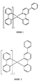
녹색 발광 분자의 한 예로는 트리스(2-페닐피리딘) 이리듐이 있으며, 하기 구조를 갖는 Ir(ppy)3를 의미한다:One example of a green luminescent molecule is tris (2-phenylpyridine) iridium, which means Ir (ppy) 3 having the structure:

본 원에서의 본 및 이후 도에서, 본 발명자는 직쇄로서 질소에서 금속(여기서는 Ir)까지의 배위 결합을 도시한다.In the present and subsequent figures herein, we show coordination bonds from nitrogen to metal (here Ir) as straight chain.
본 원에서 사용된 바와 같이, 용어 '유기'는 중합체 물질뿐만 아니라 유기 광전자 소자 제조에 사용될 수 있는 소분자 유기 물질을 포함한다. '소분자'는 중합체가 아닌 임의의 유기 물질을 의미하며, '소분자들'은 실질적으로 상당히 클 수 있다. 소분자는 일부 환경에서 반복 단위를 포함할 수 있다. 예를 들어, 치환기로서 장쇄 알킬기를 사용하는 것은 상기 '소분자' 부류로부터의 분자를 제거하지 않는다. 소분자는 또한, 예를 들어 중합체 주쇄 상의 펜던트기로서 또는 그 주쇄의 일부로서 중합체에 포함될 수 있다. 소분자는 또한 덴드리머의 중심 부분으로서 작용할 수 있으며, 이는 그 중심 부분 상에 형성된 일련의 화학적 쉘(shell)로 구성되어 있다. 덴드리머의 중심 부분은 형광성 또는 인광성 소분자 발광체일 수 있다. 덴드리머는 '소분자'일 수 있으며, OLED 분야에서 현재 사용되는 모든 덴드리머는 소분자인 것으로 생각된다.As used herein, the term 'organic' includes not only polymeric materials but also small molecule organic materials that can be used to make organic optoelectronic devices. 'Small molecule' means any organic material that is not a polymer, and 'small molecules' may be substantially quite large. Small molecules may include repeat units in some circumstances. For example, using long chain alkyl groups as substituents does not remove molecules from this 'small molecule' class. Small molecules may also be included in the polymer, for example as pendant groups on the polymer backbone or as part of its backbone. Small molecules may also serve as the central portion of the dendrimer, which consists of a series of chemical shells formed on the central portion. The central portion of the dendrimer may be a fluorescent or phosphorescent small molecule emitter. Dendrimers can be 'small molecules', and all dendrimers currently used in the OLED field are believed to be small molecules.
본 원에서 사용되는 바와 같이, '정상부'는 기재로부터 가장 먼 것을 의미하는 반면에, '바닥부'는 기재에 가장 가까운 것을 의미한다. 제1층이 제2층 '상에 배치된' 것으로 기술된 경우, 제1 층은 기재로부터 더 멀리 배치되어 있다. 제1 층이 제2 층'과 접촉하는 것'으로 명시되지 않는 한, 제1 및 제2 층 사이에 다른 층이 존재할 수 있다. 예를 들어, 다양한 유기층이 사이에 존재할 수 있지만, 캐소드가 애노드 '상에 배치되는' 것으로 기술될 수 있다.As used herein, 'top' means the furthest from the substrate, while 'bottom' means the closest to the substrate. If the first layer is described as 'disposed on' the second layer, the first layer is disposed farther from the substrate. Other layers may be present between the first and second layers unless the first layer is specified as 'in contact with the second layer'. For example, various organic layers may be present between, but the cathode may be described as being 'placed on' the anode.
본 원에서 사용되는 바와 같이, '용액 가공가능한'이란 용액 또는 현탁액 형태로 액체 매질에 및/또는 이로부터 이송되거나, 분산되거나 또는 용해될 수 있다는 것을 의미한다.As used herein, 'solution processable' means that it can be transported, dispersed or dissolved in and / or from a liquid medium in the form of a solution or suspension.
리간드는 그 리간드가 발광성 물질의 광활성 특성에 직접적으로 기여하는 것으로 고려되는 경우 '광활성'이라 언급된다. 보조 리간드가 광활성 리간드의 특성을 변경할 수 있더라도, 그 리간드가 발광 물질의 광활성 특성에 기여하지 않는 경우, 리간드는 '보조적'이라 일컬을 수 있다.A ligand is referred to as 'photoactive' when the ligand is considered to directly contribute to the photoactive properties of the luminescent material. Although the auxiliary ligand may alter the properties of the photoactive ligand, if the ligand does not contribute to the photoactive properties of the luminescent material, the ligand may be referred to as 'secondary'.
본 명세서에 사용되는 바와 같이, 그리고 당업자에 의해 일반적으로 이해되는 바와 같이, 제1 에너지 준위가 진공 에너지 준위에 보다 가깝다면, 제1 "최고 점유 분자 궤도"(HOMO) 또는 "최저 비점유 분자 궤도"(LUMO) 에너지 준위가 제2 HOMO 또는 LUMO 에너지 준위"보다 더 크거나" 또는 "보다 더 높다". 이온화 포텐셜(IP)은 진공 준위에 대하여 음의 에너지로서 측정되기 때문에, 더 높은 HOMO 에너지 준위는 더 작은 절대값을 갖는 IP(음의 값이 더 작은 IP)에 상응한다. 유사하게, 더 높은 LUMO 에너지 준위는 더 작은 절대값을 갖는 전자 친화력(EA)(음의 값이 더 작은 EA)에 상응한다. 진공 준위가 맨 위에 있는 종래의 에너지 준위 다이어그램에서, 물질의 LUMO 에너지 준위는 동일한 물질의 HOMO 에너지 준위보다 더 높다. "더 높은" HOMO 또는 LUMO 에너지 준위는 "더 낮은" HOMO 또는 LUMO 에너지 준위보다 그러한 다이어그램의 맨 위에 더 가깝게 나타난다.As used herein, and as generally understood by one of ordinary skill in the art, if the first energy level is closer to the vacuum energy level, the first "highest occupied molecular orbital" (HOMO) or "lowest unoccupied molecular orbital" "(LUMO) energy level is greater than" or "higher" than the second HOMO or LUMO energy level. Since ionization potential (IP) is measured as negative energy relative to the vacuum level, higher HOMO energy levels correspond to IPs with smaller absolute values (smaller negative IPs). Similarly, higher LUMO energy levels correspond to electron affinity (EA) with lower absolute values (EA with lower negative values). In a conventional energy level diagram where the vacuum level is at the top, the LUMO energy level of the material is higher than the HOMO energy level of the same material. "Higher" HOMO or LUMO energy levels appear closer to the top of such diagrams than "lower" HOMO or LUMO energy levels.
본 원에서 사용되고, 당업자에게 일반적으로 이해되게 되는 바와 같이, 제1 작용도가 보다 높은 절대값을 갖는 경우 제1 작용도는 제2 작용도에 대해 '보다 크다' 또는 '보다 높다'. 작용도는 일반적으로 진공 수준에 대한 음수로서 특정하기 때문에, 이는 '더욱 높은' 작용도가 더욱 음성이라는 것을 의미한다. 진공 수준이 정상부에 있는 통상의 에너지 준위도에서, '보다 높은' 작용도는 상기 진공 수준으로부터 하향으로 더 멀리 예시된다. 따라서, HOMO 및 LUMO 에너지 수준의 정의는 작용도 이외의 상이한 통상예를 따른다.As used herein and as will be generally understood by one of ordinary skill in the art, the first degree of functionality is 'greater' or 'higher' for the second degree of activity when the first degree of activity has a higher absolute value. Since the degree of action is usually specified as a negative number for the vacuum level, this means that the 'higher' degree of action is more negative. At typical energy levels where the vacuum level is at the top, the 'higher' functionality is illustrated farther downward from the vacuum level. Thus, the definitions of HOMO and LUMO energy levels follow different conventions than functionality.
OLED에 대한 추가 세부 사항, 및 전술한 정의는 미국 특허 7,279,704호에서 확인할 수 있으며, 이는 그 전체로 본 원에서 참조 인용된다.Further details about the OLED, and the foregoing definitions, can be found in US Pat. No. 7,279,704, which is incorporated herein by reference in its entirety.
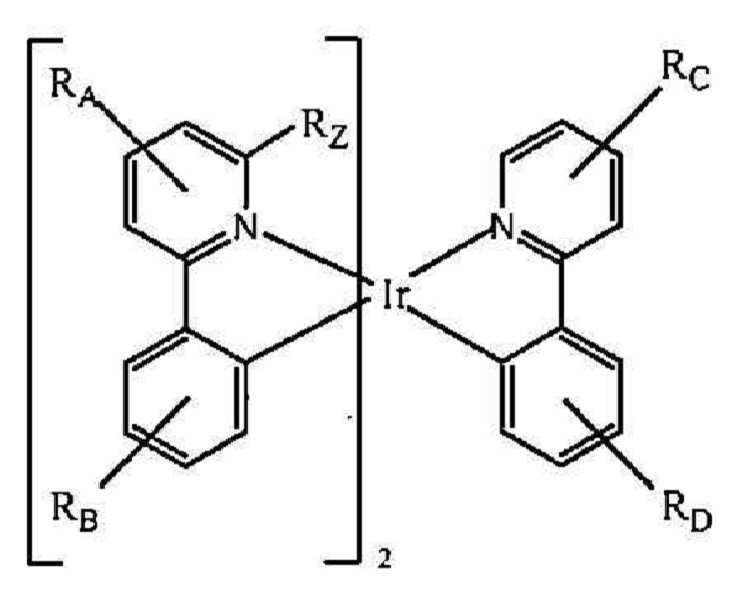
연장된 컨쥬게이팅을 갖는 이종리간드성 Ir(Ⅲ) 착물의 제조 방법이 제공된다. 상기 방법은Methods of making heteroligand Ir (III) complexes with extended conjugation are provided. The method is


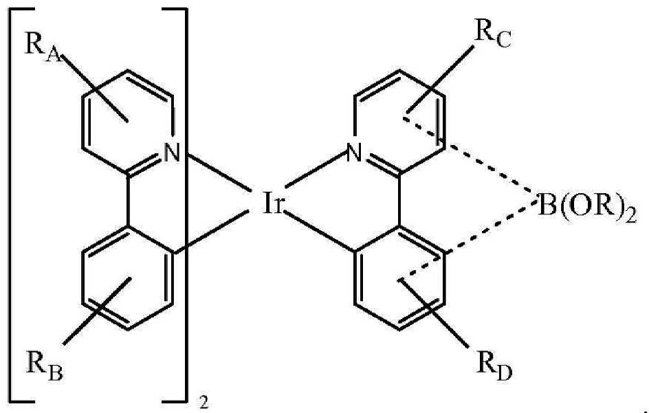
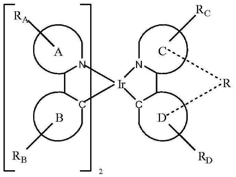
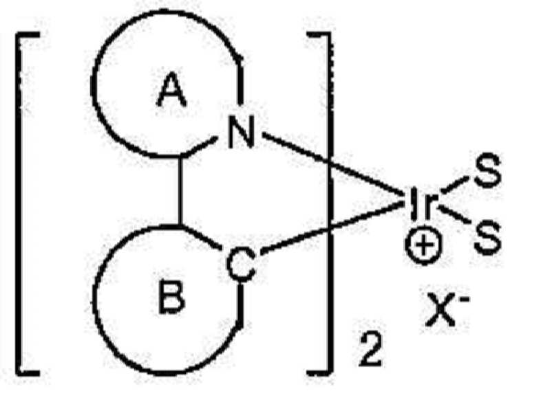
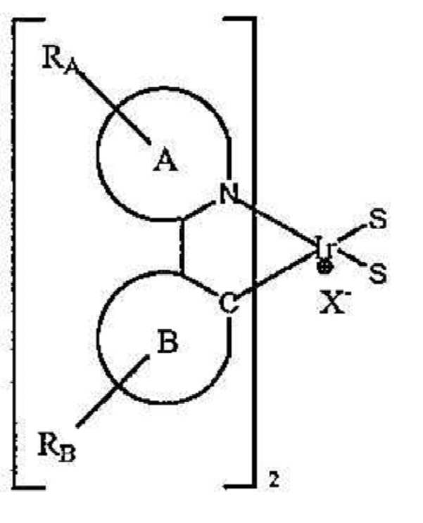
S는 중성 리간드이다. X는 카운터 이온이다. 바람직하게는, S는 트리플레이트, 토실레이트, 트리플루오로아세테이트, 테트라플루오로보레이트 및 헥사플루오로포스페이트로 구성된 군으로부터 선택된다. A 및 B는 각각 독립적으로 5원 또는 6원 방향족 또는 헤테로방향족 고리이고, A-B는 고리 A 상의 질소 원자 및 고리 B 상의 sp2 혼성화 탄소 원자를 통해 상기 이리듐에 배위 결합된 방향족 또는 헤테로방향족 고리의 결합쌍을 나타낸다. C 및 D는 각각 독립적으로 5원 또는 6원 방향족 또는 헤테로방향족 고리이고, C-D는 고리 C 상의 질소 고리 원자 및 고리 D 상의 sp2 혼성화 탄소 원자를 통해 상기 이리듐에 배위 결합된 방향족 또는 헤테로방향족 고리의 결합쌍을 나타낸다. RA, RB, RC 및 RD는 각각 독립적으로 비치환, 알킬, 헤테로알킬, 아릴 또는 헤테로아릴 기로 구성된 군으로부터 선택된다. RA, RB, RC 및 RD 각각은 1 이상의 치환기를 나타낸다. 바람직하게는, RA, RB, RC 및 RD는 벤젠, 피리미딘, 피리딘, 티오펜, 티아나프텐, 불소, 카르바졸 및 디벤조티오펜으로 구성된 군으로부터 선택된다. R은 알킬, 헤테로알킬 또는 퍼플루오로알킬 기이고, 상기 2개의 R은 임의로 결합하여 고리를 형성한다.S is a neutral ligand. X is a counter ion. Preferably, S is selected from the group consisting of triflate, tosylate, trifluoroacetate, tetrafluoroborate and hexafluorophosphate. A and B are each independently a 5- or 6-membered aromatic or heteroaromatic ring, and AB is a bond of an aromatic or heteroaromatic ring coordinated to the iridium via a nitrogen atom on ring A and an sp 2 hybridized carbon atom on ring B Indicates a pair. C and D are each independently a 5- or 6-membered aromatic or heteroaromatic ring, and CD is an aromatic or heteroaromatic ring coordinated to the iridium via a nitrogen ring atom on ring C and an sp 2 hybridized carbon atom on ring D Represents a binding pair. R A , R B , R C and R D are each independently selected from the group consisting of unsubstituted, alkyl, heteroalkyl, aryl or heteroaryl groups. R A , R B , R C and R D each represent one or more substituents. Preferably, R A , R B , R C and R D are selected from the group consisting of benzene, pyrimidine, pyridine, thiophene, thianaphthene, fluorine, carbazole and dibenzothiophene. R is an alkyl, heteroalkyl or perfluoroalkyl group, wherein the two R's optionally combine to form a ring.
또한, 인광성 발광 물질이 제공된다. 상기 물질은 이종환 고리 상에서 연장 컨쥬게이팅된 이종리간드성 착물이다. 상기 물질은 유기 발광 소자에서 이롭게 사용될 수 있다. 특히, 상기 물질은 상기 소자의 발광 도판트로서 유용할 수 있다. 상기 물질은 하기로 구성된 군으로부터 선택된다:In addition, a phosphorescent light emitting material is provided. The material is a heteroligand complex extended on a heterocyclic ring. The material can be advantageously used in organic light emitting devices. In particular, the material may be useful as a light emitting dopant of the device. The material is selected from the group consisting of:
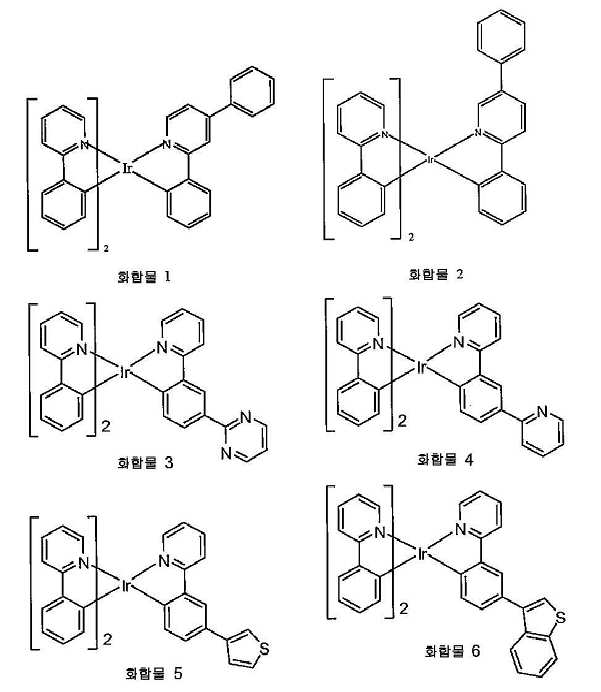
한 양태에서, 화합물 1이 바람직할 수 있다. 또다른 양태에서, 화합물 2가 바람직할 수 있다.In one embodiment, compound 1 may be preferred. In another embodiment,
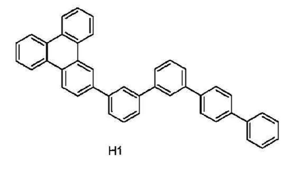
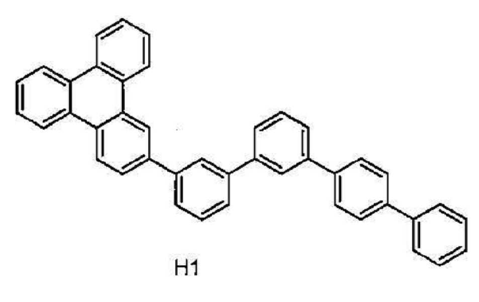
또한, 유기 발광 소자가 제공된다. 상기 소자는 애노드, 캐소드, 및 그 애노드와 캐소드 사이에 배치된 유기층을 가지며, 여기서 상기 유기층은 화합물 1∼6으로부터 선택되는 화합물을 포함한다. 상기 유기층은 호스트를 추가로 포함할 수 있다. 바람직하게는, 상기 호스트는 트리페닐렌기를 포함한다. 더욱 바람직하게는, 상기 호스트는 터페닐로 추가 치환된 트리페닐렌을 포함한다. 가장 바람직하게는, 상기 호스트는 H1이다.In addition, an organic light emitting device is provided. The device has an anode, a cathode, and an organic layer disposed between the anode and the cathode, wherein the organic layer comprises a compound selected from compounds 1-6. The organic layer may further include a host. Preferably, the host comprises a triphenylene group. More preferably, the host comprises triphenylene further substituted with terphenyl. Most preferably, the host is H1.
소비재가 또한 제공된다. 상기 생성물을 애노드, 캐소드, 및 그 애노드와 캐소드 사이에 배치된 유기층을 가지며, 여기서 상기 유기층은 화합물 1∼6으로부터 선택되는 화합물을 추가로 포함한다.Consumer goods are also provided. The product has an anode, a cathode, and an organic layer disposed between the anode and the cathode, wherein the organic layer further comprises a compound selected from compounds 1-6.
이종리간드성 이리듐 화합물이 제공되며, 이는 유기 발광 소자에 이롭게 사용될 수 있다. 상기 이종리간드성 화합물은 하기로 구성된 군으로부터 선택된다:Heteroligand iridium compounds are provided, which can be advantageously used in organic light emitting devices. The heteroligand compound is selected from the group consisting of:

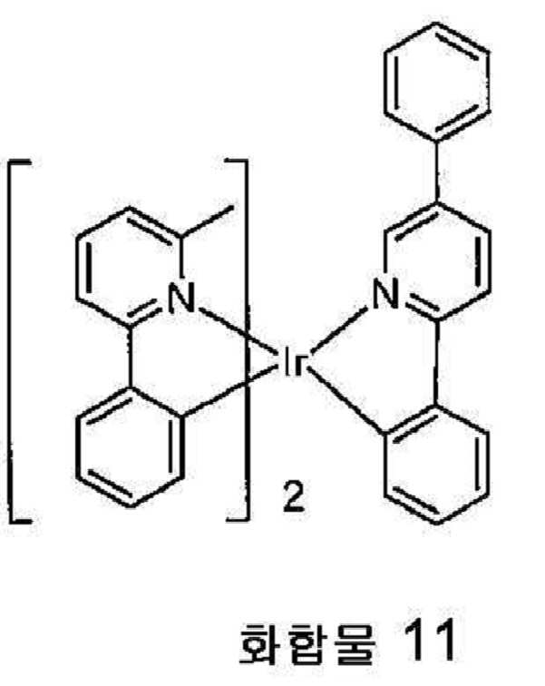
한 양태에서, 화합물 8이 바람직할 수 있다. 또다른 양태에서, 화합물 9가 바람직할 수 있다. 또다른 양태에서, 화합물 10이 바람직할 수 있다. 추가 양태에서, 화합물 11이 바람직할 수 있다. 또다른 양태에서, 화합물 12가 바람직할 수 있다. 추가 양태에서, 화합물 13이 바람직할 수 있다. 또다른 양태에서, 화합물 14가 바람직할 수 있다.In one embodiment, compound 8 may be preferred. In another embodiment, compound 9 may be preferred. In another embodiment, compound 10 may be preferred. In further embodiments, compound 11 may be preferred. In another embodiment,
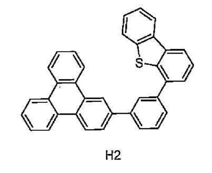
또한, 유기 발광 소자가 제공된다. 상기 소자는 애노드, 캐소드, 및 그 애노드와 캐소드 사이에 배치된 유기층을 가지며, 상기 유기층은 화합물 8∼14로부터 선택되는 화합물을 포함한다. 상기 유기층은 아릴 또는 헤테로아릴에 의해 추가로 치환된 트리페닐렌기를 갖는 호스트를 추가로 포함한다. 바람직하게는, 상기 호스트는 터페닐 또는 디벤조티오펜에 의해 추가로 치환되는 트리페닐렌기를 함유한다. 더욱 바람직하게는, 상기 호스트는 H1 또는 H2 이다.In addition, an organic light emitting device is provided. The device has an anode, a cathode, and an organic layer disposed between the anode and the cathode, the organic layer comprising a compound selected from compounds 8-14. The organic layer further comprises a host having a triphenylene group further substituted by aryl or heteroaryl. Preferably, the host contains a triphenylene group which is further substituted by terphenyl or dibenzothiophene. More preferably, the host is H1 or H2.
소비재가 또한 제공된다. 상기 생성물은 애노드, 캐소드, 및 그 애노드와 캐소드 사이에 배치된 유기층을 갖는 소자를 함유하며, 여기서 상기 유기층은 화합물 8∼14로부터 선택되는 화합물을 추가로 포함한다.Consumer goods are also provided. The product contains an element having an anode, a cathode, and an organic layer disposed between the anode and the cathode, wherein the organic layer further comprises a compound selected from compounds 8-14.
또한, 유의적인 리간드 스크램블링 없는 이종리간드성 화합물의 제조 방법이 제공된다. 상기 방법은Also provided are methods of preparing heteroligand compounds without significant ligand scrambling. The method is


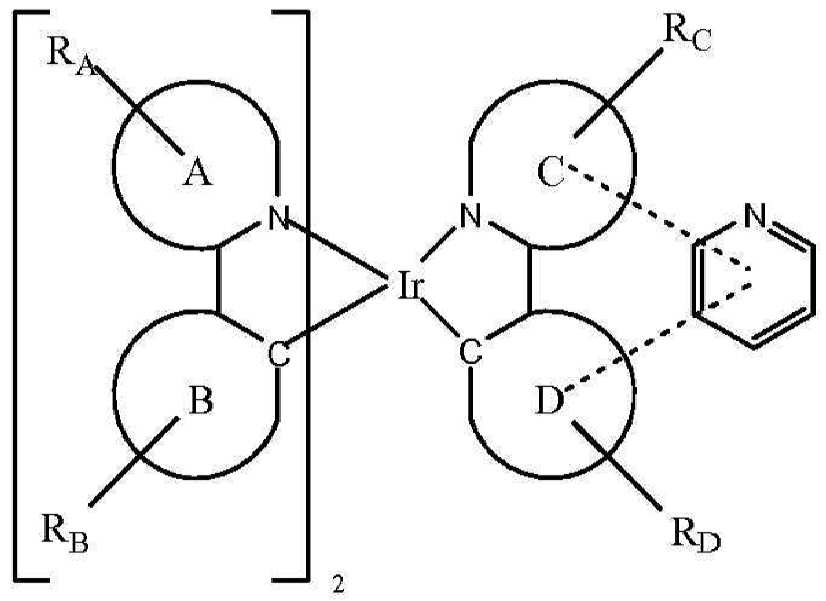
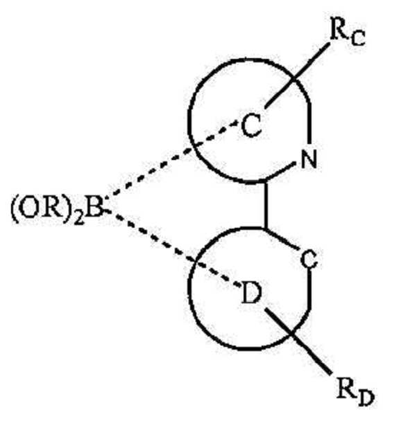
화학식 Ir(LA-B)2(LC-D)를 갖는 이종리간드성 화합물이 제공된다. LA-B는 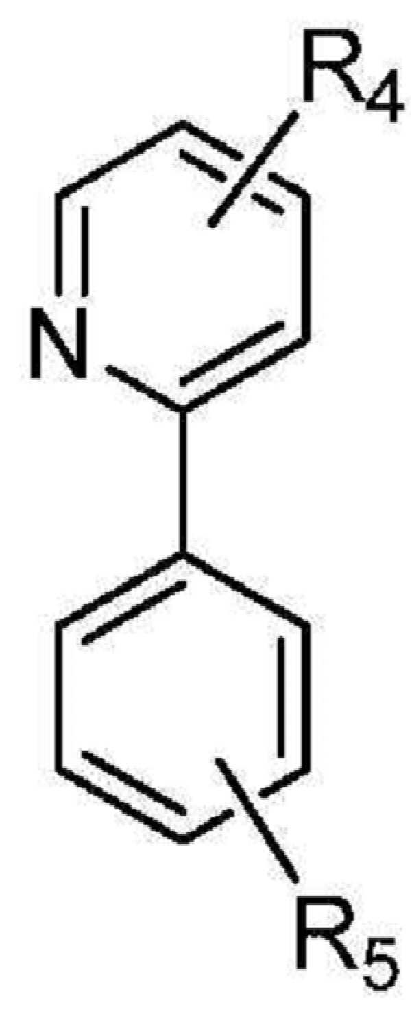


신규한 인광성 유기 물질이 제공된다. 상기 유기 물질은 상기 치환기 아릴이 통상의 비치환된 페닐-페닐보다 많이 평면으로부터 뒤틀리도록 아릴 치환기(즉, 본 문헌에서는 뒤틀린 아릴) 및 알킬 치환기를 갖는 1 이상의 리간드를 함유하는 화합물이다. 상기 화합물은 유기 발광 소자에 이롭게 사용될 수 있다. 특히, 상기 화합물은 상기 소자에서 발광 도판트로서 유용할 수 있다.Novel phosphorescent organic materials are provided. The organic material is a compound containing one or more ligands having aryl substituents (ie, warped aryls) and alkyl substituents such that the substituent aryl is twisted out of plane more than conventional unsubstituted phenyl-phenyl. The compound can be advantageously used in organic light emitting devices. In particular, the compound may be useful as a light emitting dopant in the device.
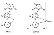
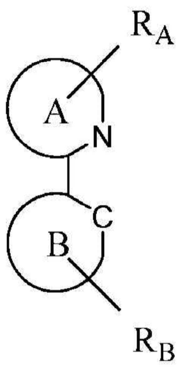
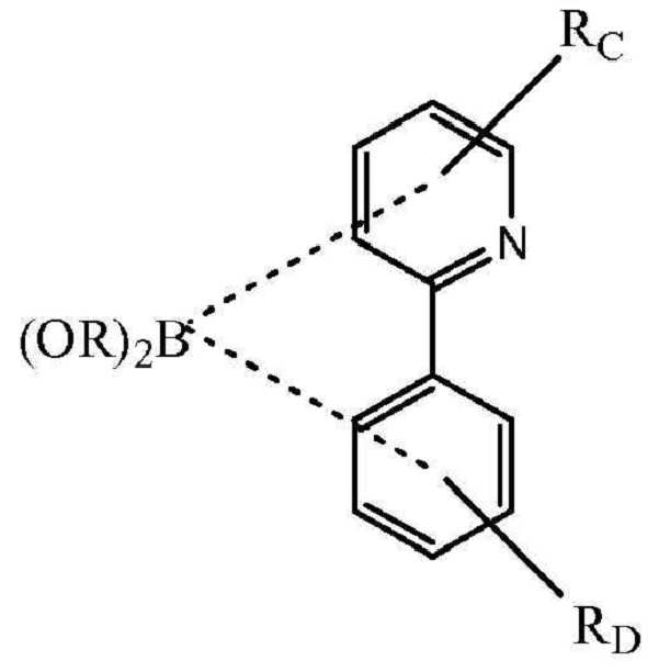
하기 구조의 리간드 L을 포함하는 화합물이 제공된다:There is provided a compound comprising a ligand L of the structure:

B 및 C는 각각 독립적으로 5원 또는 6원 탄소환 또는 이종환 고리이다. A-B는 고리 A 상의 질소 원자 및 고리 B 상의 sp2 혼성화 탄소 원자를 통해 금속 M에 배위 결합된 탄소환 또는 이종환 고리의 결합쌍을 나타낸다. A-C는 탄소환 및 이종환 고리의 결합쌍을 나타낸다. Ra, Rb 및 Rc는 모노, 디, 트리 또는 테트라 치환을 나타낼 수 있다. Ra, Rb 및 Rc는 독립적으로 수소, 알킬, 알콕시, 아미노, 알케닐, 알키닐, 아릴킬, 아릴 및 헤테로아릴로 구성된 군으로부터 선택된다. X1, X2, X3, X4, X5, X6, X7, X8 및 X9은 독립적으로 탄소 및 질소로부터 선택된다. 바람직하게는, A는 피리딘이다. R1 및 R2는 독립적으로 수소, 알킬, 알콕시, 아미노, 알케닐, 알키닐, 아릴킬, 아릴 및 헤테로아릴로 구성된 군으로부터 선택된다. 고리 C에 인접한 R1, R2 및 Ra 치환기들 중 1 이상이 수소가 아니다. 바람직하게는, 고리 C에 인접한 R1, R2 및 Ra 치환기들 중 하나만이 수소가 아니다. 바람직하게는, 고리 C에 인접한 R1, R2 및 Ra 치환기들 중 하나만이 알킬이다. 더욱 바람직하게는, 고리 C에 인접한 R1, R2 및 Ra 치환기들 중 하나만이 에틸이다. 가장 바람직하게는, 고리 C에 인접한 R1, R2 및 Ra 치환기들 중 하나만이 메틸이다. 상기 리간드 L은 원자 번호가 40보다 큰 금속 M에 배위 결합된다. 바람직하게는, 금속 M은 Ir이다.B and C are each independently a 5- or 6-membered carbocyclic ring or a heterocyclic ring. AB represents a bonding pair of carbocyclic or heterocyclic rings coordinated to metal M via a nitrogen atom on ring A and an sp 2 hybridized carbon atom on ring B. AC represents a bonding pair of carbocyclic and heterocyclic rings. R a , R b and R c may represent mono, di, tri or tetra substitutions. R a , R b and R c are independently selected from the group consisting of hydrogen, alkyl, alkoxy, amino, alkenyl, alkynyl, arylalkyl, aryl and heteroaryl. X 1 , X 2 , X 3 , X 4 , X 5 , X 6 , X 7 , X 8 and X 9 are independently selected from carbon and nitrogen. Preferably, A is pyridine. R 1 and R 2 are independently selected from the group consisting of hydrogen, alkyl, alkoxy, amino, alkenyl, alkynyl, arylalkyl, aryl and heteroaryl. At least one of the R 1 , R 2 and R a substituents adjacent to the ring C is not hydrogen. Preferably, only one of the R 1 , R 2 and R a substituents adjacent to ring C is not hydrogen. Preferably, only one of the R 1 , R 2 and R a substituents adjacent to ring C is alkyl. More preferably, only one of the R 1 , R 2 and R a substituents adjacent to ring C is ethyl. Most preferably, only one of the R 1 , R 2 and R a substituents adjacent to ring C is methyl. The ligand L is coordinately bonded to the metal M having an atomic number greater than 40. Preferably, the metal M is Ir.
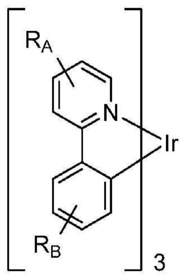
상기 화합물의 예로는 하기 구조를 갖는 화합물을 들 수 있다:Examples of the compound include a compound having the structure:

m은 금속 M의 산화수이다. 바람직하게는 상기 금속 M은 Ir이다. 바람직하게는, A는 피리딘이고, n은 1 이상이다. L'은 1가 음이온성의 2자리 리간드이다. 바람직하게는, C에 인접한 R1, R2 및 Ra 치환기들 중 하나만이 수소가 아니다. 바람직하게는, C에 인접한 R1, R2 및 Ra 치환기들 중 하나만이 알킬이다. 더욱 바람직하게는, C에 인접한 R1, R2 및 Ra 치환기들 중 하나만이 에틸이다. 가장 바람직하게는, C에 인접한 R1, R2 및 Ra 치환기들 중 하나만이 메틸이다.m is the oxidation number of the metal M. Preferably the metal M is Ir. Preferably, A is pyridine and n is at least 1. L 'is a monovalent anionic bidentate ligand. Preferably, only one of the R 1 , R 2 and R a substituents adjacent to C is not hydrogen. Preferably, only one of the R 1 , R 2 and R a substituents adjacent to C is alkyl. More preferably, only one of the R 1 , R 2 and R a substituents adjacent to C is ethyl. Most preferably, only one of the R 1 , R 2 and R a substituents adjacent to C is methyl.
화학식 (Ⅱ)를 갖는 화합물의 구체적인 예가 제공되고, 화합물 15∼20을 들 수 있다. R은 수소가 아니다. 바람직하게는 R은 알킬이다.Specific examples of the compound having the formula (II) are provided, and compounds 15 to 20 are mentioned. R is not hydrogen. Preferably R is alkyl.
화합물 21∼화합물 37을 비롯한 화학식 (Ⅱ)을 갖는 화합물의 특정예가 제시된다. 한 양태에서, 화합물 21, 22, 25, 29, 30, 31 및 34가 바람직한 화합물일 수 있다.Specific examples of compounds having Formula (II) are shown, including Compounds 21-37. In one embodiment, compounds 21, 22, 25, 29, 30, 31 and 34 may be preferred compounds.
한 양태에서, 하기로 구성된 군으로부터 선택된 화합물이 제공된다:In one embodiment there is provided a compound selected from the group consisting of:


R1, R2, R3 및 R4 중 1 이상이 수소가 아니다. R5는 수소, 알킬, 알콕시, 아미노, 알케닐, 알키닐, 아릴킬, 아릴 및 헤테로아릴로 구성된 군으로부터 선택된다. 바람직하게는, A는 피리딘이다. 한 양태에서, R1 및 R2는 수소이고, R3 및 R4 중 하나는 알킬이다. 예시적 화합물로는 화합물 21∼24, 29∼34, 36 및 37을 들 수 있다. 또다른 양태에서, R1 및 R2 중 1 이상은 알킬이고, R3 및 R4는 수소이다. 예시적 화합물로는 화합물 25∼28 및 35를 들 수 있다.At least one of R 1 , R 2 , R 3 and R 4 is not hydrogen. R 5 is selected from the group consisting of hydrogen, alkyl, alkoxy, amino, alkenyl, alkynyl, arylalkyl, aryl and heteroaryl. Preferably, A is pyridine. In one embodiment, R 1 and R 2 are hydrogen and one of R 3 and R 4 is alkyl. Exemplary compounds include compounds 21-24, 29-34, 36, and 37. In another embodiment, at least one of R 1 and R 2 is alkyl and R 3 and R 4 are hydrogen. Exemplary compounds include compounds 25-28 and 35.
또다른 양태에서, 상기 화합물은 하기로 구성된 군으로부터 선택된다:In another embodiment, the compound is selected from the group consisting of:

화학식 (Ⅱ)를 갖는 화합물은 동종리간드성 화합물 및 이종리간드성 화합물을 포함한다. 동종리간드성 화합물의 예로는 화합물 21∼24 및 35를 들 수 있다. 이종리간드성 화합물의 예로는 25∼34, 36 및 37을 들 수 있다.Compounds having the formula (II) include homoligand compounds and heteroligand compounds. Examples of the homoleptic compound include
한 양태에서, 하기로 구성된 군으로부터 선택되는 리간드 L'을 갖는 화합물이 제공된다:In one embodiment there is provided a compound having a ligand L 'selected from the group consisting of:

R'1, R'2 및 R'3는 독립적으로 수소, 알킬, 알콕시, 아미노, 알케닐, 알키닐, 아릴킬, 아릴 및 헤테로아릴로 구성된 군으로부터 선택된다.R ' 1 , R' 2 and R ' 3 are independently selected from the group consisting of hydrogen, alkyl, alkoxy, amino, alkenyl, alkynyl, arylalkyl, aryl and heteroaryl.
한 양태에서, 상기 치환기(즉, 상기 아릴 치환기 중에 뒤틀림을 유도하는 알킬 치환기)가 상기 리간드 L의 피리딘 고리 상에 존재하는 화합물이 바람직하다. 바람직하게는, 상기 화합물은 화합물 21∼23, 29∼31, 34, 36 및 37로 구성된 군으로부터 선택된다.In one embodiment, preference is given to compounds wherein the substituents (ie, alkyl substituents that induce distortion in the aryl substituents) are present on the pyridine ring of the ligand L. Preferably, the compound is selected from the group consisting of compounds 21-23, 29-31, 34, 36 and 37.
또다른 양태에서, 알킬 치환기가 상기 피리딘 고리의 질소에 대해서 파라 위치에 존재하는 화합물이 특히 바람직할 수 있다. 바람직하게는, 상기 화합물은 화합물 21, 22, 29∼31, 34, 36 및 37로 구성된 군으로부터 선택된다.In another aspect, particular preference may be given to compounds in which the alkyl substituent is at the para position relative to the nitrogen of the pyridine ring. Preferably, the compound is selected from the group consisting of
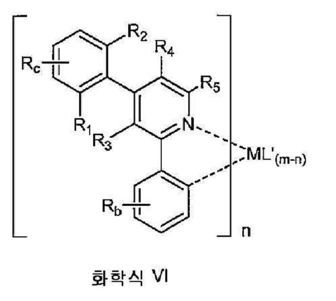
유기 발광 소자가 또한 제공된다. 상기 소자는 애노드, 캐소드, 및 그 애노드와 캐소드 사이에 배치된 유기층을 포함하며, 여기서 상기 유기층은 전술한 바와 같은 화학식 (I)의 화합물을 포함한다. 화학식 (I)을 갖는 화합물에 바람직한 것으로 기술된 치환기에 대한 선택 사항은 화학식 (I)의 화합물을 포함하는 소자에 적용하는 데 또한 바람직하다. 상기 선택 사항으로는 금속 M; 화학식 (Ⅱ)∼(Ⅵ); C에 인접한 치환기 R, R1, R2, R3, R4, R5 및 Ra 치환기; 고리 C의 위치; 고리 A, B 및 C에 대해 기술된 것을 들 수 있다.An organic light emitting element is also provided. The device comprises an anode, a cathode, and an organic layer disposed between the anode and the cathode, wherein the organic layer comprises a compound of formula (I) as described above. Options for substituents described as being preferred for compounds having formula (I) are also preferred for application to devices comprising compounds of formula (I). The options include metal M; General formulas (II) to (VI); Substituents adjacent to C are R, R 1 , R 2 , R 3 , R 4 , R 5 and R a substituents; Position of ring C; And those described for the rings A, B and C.
한 양태에서, 상기 소자는 전술한 바와 같은 화학식 (Ⅱ)을 갖는 화합물을 포함한다. 바람직하게는, 상기 금속 M은 Ir이다. 바람직하게는 A는 피리딘이다. 또다른 양태에서, 상기 소자는 전술한 바와 같은 화학식 (Ⅲ) 또는 화학식 (Ⅳ)를 갖는 화합물을 포함한다. C에 인접한 R1, R2 및 Ra 중 하나만이 알킬인 화합물을 함유하는 소자가 또한 바람직할 수 있다. 또다른 양태에서, 상기 소자는 전술한 바와 같은 화학식 (V) 또는 화학식 (Ⅵ)을 갖는 화합물을 포함한다. 상기 소자가 화합물 21∼화합물 37로 구성된 군으로부터 선택된 화합물을 함유하는 특정 소자가 제공된다. 바람직하게는, 상기 소자는 화합물 21, 화합물 22, 화합물 25, 화합물 29, 화합물 30, 화합물 31 또는 화합물 34를 함유한다.In one embodiment, the device comprises a compound having formula (II) as described above. Preferably, the metal M is Ir. Preferably A is pyridine. In another embodiment, the device comprises a compound having formula (III) or formula (IV) as described above. Also preferred are devices containing compounds in which only one of R 1 , R 2 and R a adjacent to C is alkyl. In another embodiment, the device comprises a compound having formula (V) or formula (VI) as described above. There is provided a specific device wherein the device contains a compound selected from the group consisting of Compounds 21-37. Preferably, the device contains
한 양태에서, 상기 유기층이 발광층이고, 화학식 (I)을 갖는 화합물이 발광 도판드인 소자가 제공된다. 더욱이, 상기 유기층은 호스트를 추가로 포함할 수 있다. 바람직하게는, 상기 호스트는 하기 구조를 가진다:In one embodiment, a device is provided wherein the organic layer is a light emitting layer and the compound having formula (I) is a light emitting dopant. Moreover, the organic layer may further comprise a host. Preferably, the host has the following structure:
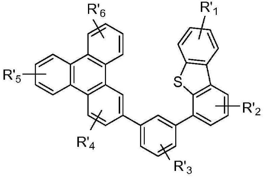
R'1, R'2, R'3, R'4, R'5 및 R'6는 독립적으로 수소, 알킬, 알콕시, 아미노, 알케닐, 알키닐, 아릴킬, 아릴 및 헤테로아릴로 구성된 군으로부터 선택된다.R ' 1 , R' 2 , R ' 3 , R' 4 , R ' 5 and R' 6 are independently a group consisting of hydrogen, alkyl, alkoxy, amino, alkenyl, alkynyl, arylalkyl, aryl and heteroaryl Is selected from.
소자를 포함하는 소비재가 또한 제공된다. 상기 소자는 애노드, 캐소드, 및 그 애노드와 캐소드 사이에 배치된 유기층을 포함하고, 여기서 상기 유기층은 전술한 바와 같은 화학식 (I)을 갖는 화합물을 포함한다. 화학식 (I)을 갖는 화합물에 대해 바람직한 것으로 기술된 치환기에 대한 선택 사항이 또한 화학식 (I)을 갖는 화합물을 포함하는 소자를 함유하는 소비재에 적용하는 데 바람직하다. 상기 선택 사항으로는 금속 M; 화학식 (Ⅱ)∼(Ⅵ); C에 인접한 치환기 R, R1, R2, R3, R4, R5 및 Ra 치환기; 고리 C의 위치; 고리 A, B 및 C에 대해 기술된 것을 들 수 있다.Consumer goods comprising the device are also provided. The device comprises an anode, a cathode, and an organic layer disposed between the anode and the cathode, wherein the organic layer comprises a compound having formula (I) as described above. Options for substituents described as being preferred for compounds having formula (I) are also preferred for application to consumer products containing devices comprising compounds having formula (I). The options include metal M; General formulas (II) to (VI); Substituents adjacent to C are R, R 1 , R 2 , R 3 , R 4 , R 5 and R a substituents; Position of ring C; And those described for the rings A, B and C.
또한, 동종리간드성 화합물의 저온 제조 방법이 제공된다. 특히, 상기 방법은 동종 Ir(Ⅲ) 화합물을 제조하기 위한 것이다. 이러한 화합물은 바람직하게는 뒤틀린 아릴을 함유할 수 있다.Also provided is a low temperature process for the preparation of homoligand compounds. In particular, the method is for preparing homogeneous Ir (III) compounds. Such compounds may preferably contain warped aryl.
동종리간드성 Ir(Ⅲ) 착물의 제1 제조 방법이 제공된다. 상기 제1 방법은A first method for producing a homoligand Ir (III) complex is provided. The first method
저비점 알콜의 존재 하에 
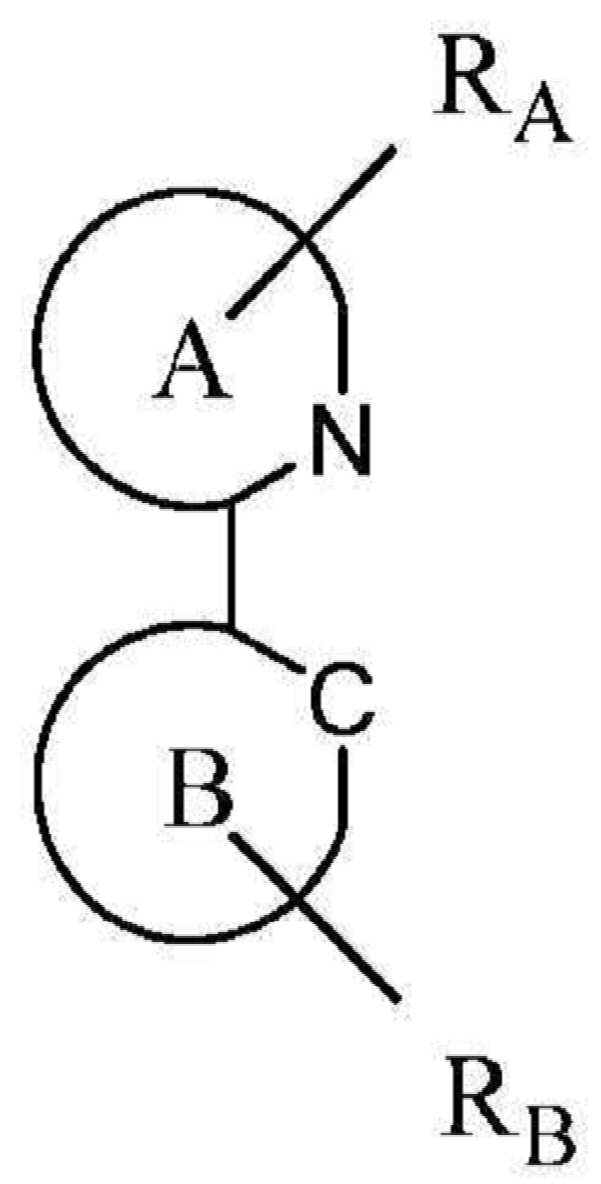

RA 및 RB 중 1 이상이 알킬기이고, 상기 알킬기는 피리딘 고리 상의 질소에 인접하지 않는다. S는 중성 리간드이다. X는 카운터 이온이다. 바람직하게는, X는 트리플레이트이다. A 및 B는 각각 독립적으로 5원 또는 6원 탄소환 또는 이종환 고리이다. A-B는 고리 A 상의 질소 원자 및 고리 B 상의 sp2 혼성화 탄소 원자를 통해 이리듐에 배위 결합된 탄소환 또는 이종환 고리의 결합쌍을 나타낸다. RA 및 RB 각각은 모노, 디, 트리 또는 테트라 치환을 나타낼 수 있다. RA 및 RB는 각각 독립적으로 수소, 알킬, 알콕시, 아미노, 알케닐, 알키닐, 아릴킬, 아릴 및 헤테로아릴로 구성된 군으로부터 선택된다.At least one of R A and R B is an alkyl group, which is not adjacent to the nitrogen on the pyridine ring. S is a neutral ligand. X is a counter ion. Preferably, X is triflate. A and B are each independently a 5- or 6-membered carbocyclic ring or a heterocyclic ring. AB represents a bonding pair of carbocyclic or heterocyclic rings coordinated to iridium via a nitrogen atom on ring A and an sp 2 hybridized carbon atom on ring B. Each of R A and R B may represent mono, di, tri or tetra substitutions. R A and R B are each independently selected from the group consisting of hydrogen, alkyl, alkoxy, amino, alkenyl, alkynyl, arylalkyl, aryl and heteroaryl.
한 양태에서, 상기 저비점 알콜은 메탄올, 에탄올, n-프로판올, 이소프로판올, n-부탄올, 1:1 비율의 에탄올과 메탄올, 2-메톡시에탄올 및 2-에톡시에탄올로 구성된 군으로부터 선택된다. 바람직하게는, 상기 저비점 알콜은 108℃에서 비등하는 이소프로판올, 78℃에서 비등하는 에탄올, 65∼78℃의 비등점을 갖는 1:1 비율의 에탄올과 메탄올로 구성된 군으로부터 선택된다. 더욱 바람직하게는, 상기 저비점 알콜은 에탄올이거나, 1:1 비율의 에탄올과 메탄올이다. 가장 바람직하게는, 상기 저비점 알콜은 1:1 비율의 에탄올과 메탄올이다. In one embodiment, the low boiling alcohol is selected from the group consisting of methanol, ethanol, n-propanol, isopropanol, n-butanol, 1: 1 ethanol and methanol, 2-methoxyethanol and 2-ethoxyethanol. Preferably, the low boiling alcohol is selected from the group consisting of isopropanol boiling at 108 ° C., ethanol boiling at 78 ° C., 1: 1 ethanol and methanol having a boiling point of 65 to 78 ° C. More preferably, the low boiling alcohol is ethanol or ethanol and methanol in a 1: 1 ratio. Most preferably, the low boiling alcohol is ethanol and methanol in a 1: 1 ratio.
바람직하게는, A는 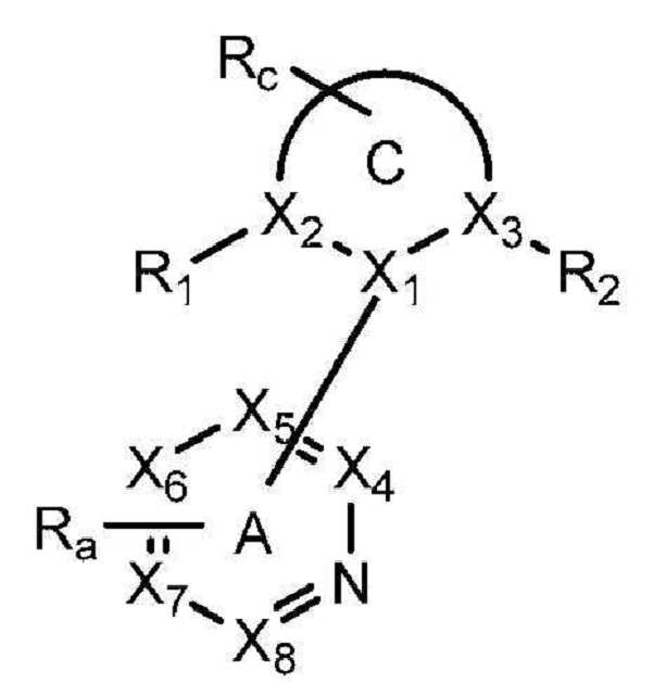
C는 5원 또는 6원 탄소환 또는 이종환 고리이다. A-C는 탄소환 및 이종환 고리의 결합쌍을 나타낸다. RA 및 RC는 모노, 디, 트리 또는 테트라 치환을 나타낼 수 있다. RA 및 RC는 독립적으로 수소, 알킬, 알콕시, 아미노, 알케닐, 알키닐, 아릴킬, 아릴 및 헤테로아릴로 구성된 군으로부터 선택된다. X1, X2, X3, X4, X5, X6, X7, X8 및 X9은 독립적으로 탄소 및 질소로부터 선택된다. R1 및 R2는 독립적으로 수소, 알킬, 알콕시, 아미노, 알케닐, 알키닐, 아릴킬, 아릴 및 헤테로아릴로 구성된 군으로부터 선택된다. C에 인접한 R1, R2 및 Ra 치환기들 중 1 이상이 수소가 아니다.C is a 5- or 6-membered carbocyclic or heterocyclic ring. AC represents a bonding pair of carbocyclic and heterocyclic rings. R A and R C may represent mono, di, tri or tetra substitutions. R A and R C are independently selected from the group consisting of hydrogen, alkyl, alkoxy, amino, alkenyl, alkynyl, arylalkyl, aryl and heteroaryl. X 1 , X 2 , X 3 , X 4 , X 5 , X 6 , X 7 , X 8 and X 9 are independently selected from carbon and nitrogen. R 1 and R 2 are independently selected from the group consisting of hydrogen, alkyl, alkoxy, amino, alkenyl, alkynyl, arylalkyl, aryl and heteroaryl. At least one of the R 1 , R 2 and R a substituents adjacent to C is not hydrogen.
한 양태에서, 제1 방법은 저비점 알콜의 존재 하에In one embodiment, the first method is in the presence of a low boiling alcohol


화합물 21, 화합물 22 및 화합물 24를 비롯한 특정 화합물은 이러한 방법을 이용하여 형성할 수 있다. Certain compounds can be formed using this method, including
동종리간드성 Ir(Ⅲ)의 제2 제조 방법이 또한 제공된다. 상기 제2 방법은 용매의 부재 하에 

RA 및 RB 중 1 이상은 알킬기이고, 상기 알킬기는 피리딘 고리 상의 질소에 인접한다. S는 중성 리간드이다. X는 카운터 이온이다. 바람직하게는, X는 트리플레이트이다. A 및 B는 각각 독립적으로 5원 또는 6원 탄소환 또는 이종환 고리이다. A-B는 고리 A 상의 질소 원자 및 고리 B 상의 sp2 혼성화 탄소 원자를 통해 이리듐에 배위 결합된 탄소환 또는 이종환 고리의 결합쌍을 나타낸다. RA 및 RB 각각은 모노, 디, 트리 또는 테트라 치환을 나타낼 수 있다. RA 및 RB는 각각 독립적으로 수소, 알킬, 알콕시, 아미노, 알케닐, 알키닐, 아릴킬, 아릴 및 헤테로아릴로 구성된 군으로부터 선택된다.At least one of R A and R B is an alkyl group, which is adjacent to the nitrogen on the pyridine ring. S is a neutral ligand. X is a counter ion. Preferably, X is triflate. A and B are each independently a 5- or 6-membered carbocyclic ring or a heterocyclic ring. AB represents a bonding pair of carbocyclic or heterocyclic rings coordinated to iridium via a nitrogen atom on ring A and an sp 2 hybridized carbon atom on ring B. Each of R A and R B may represent mono, di, tri or tetra substitutions. R A and R B are each independently selected from the group consisting of hydrogen, alkyl, alkoxy, amino, alkenyl, alkynyl, arylalkyl, aryl and heteroaryl.
바람직하게는, A는 
C는 5원 또는 6원 탄소환 또는 이종환 고리이다. A-C는 탄소환 및 이종환 고리의 결합쌍을 나타낸다. RA 및 RC는 모노, 디, 트리 또는 테트라 치환을 나타낼 수 있다. RA 및 Rc는 독립적으로 수소, 알킬, 알콕시, 아미노, 알케닐, 알키닐, 아릴킬, 아릴 및 헤테로아릴로 구성된 군으로부터 선택된다. X1, X2, X3, X4, Xs, X6, X7, X8 및 X9은 독립적으로 탄소 및 질소로부터 선택된다. R1 및 R2는 독립적으로 수소, 알킬, 알콕시, 아미노, 알케닐, 알키닐, 아릴킬, 아릴 및 헤테로아릴로 구성된 군으로부터 선택된다. C에 인접한 R1, R2 및 Ra 치환기들 중 1 이상은 수소가 아니다.C is a 5- or 6-membered carbocyclic or heterocyclic ring. AC represents a bonding pair of carbocyclic and heterocyclic rings. R A and R C may represent mono, di, tri or tetra substitutions. R A and R c are independently selected from the group consisting of hydrogen, alkyl, alkoxy, amino, alkenyl, alkynyl, arylalkyl, aryl and heteroaryl. X 1 , X 2 , X 3 , X 4 , Xs, X 6 , X 7 , X 8 and X 9 are independently selected from carbon and nitrogen. R 1 and R 2 are independently selected from the group consisting of hydrogen, alkyl, alkoxy, amino, alkenyl, alkynyl, arylalkyl, aryl and heteroaryl. At least one of the R 1 , R 2 and R a substituents adjacent to C is not hydrogen.
한 양태에서, 제2 방법은 용매의 부재 하에In one embodiment, the second method is in the absence of solvent


화합물 23을 비롯한 특정 화합물을 이러한 방법을 이용하여 형성할 수 있다.Certain compounds can be formed using this method, including compound 23.
도 1은 유기 발광 소자를 나타낸다.
도 2는 개별 전자 수송층을 갖지 않는 역전 유기 발광 소자(inverted organic light emitting device)를 나타낸다.
도 3은 특정 구조를 갖는 PHOLED를 나타낸다.
도 4는 이종리간드성 Ir(Ⅲ) 화합물의 제조 방법을 나타낸다.
도 5는 연장된 컨쥬게이팅을 갖는 이종리간드성 Ir(Ⅲ) 착물을 나타낸다.
도 6는 이종리간드성 Ir(Ⅲ) 화합물의 제조 방법을 나타내다.
도 7은 뒤틀린 아릴을 함유하는 리간드 및 뒤틀린 아릴을 함유하는 리간드를 포함하는 화합물을 나타낸다.
도 8은 예시적 화합물을 나타낸다.
도 9은 동종리간드성 Ir(Ⅲ) 화합물의 제조 방법을 나타낸다.1 shows an organic light emitting device.
2 shows an inverted organic light emitting device without an individual electron transport layer.
3 shows a PHOLED having a specific structure.
4 shows a method for producing a heteroleptic Ir (III) compound.
5 shows heteroligand Ir (III) complexes with extended conjugation.
6 shows a method for producing a heteroleptic Ir (III) compound.
7 shows a compound comprising a ligand containing warped aryl and a ligand containing warped aryl.
8 shows exemplary compounds.
9 shows a method for producing a homoligand Ir (III) compound.
일반적으로, OLED는 애노드와 캐소드 사이에 배치되고 이에 전기적으로 연결되어 있는 1 이상의 유기층을 포함할 수 있다. 전류가 인가되는 경우, 상기 유기층(들)에 상기 애노드는 정공을 주입할 수 있고, 상기 캐소드는 전자를 주입한다. 주입된 정공 및 전자는 각각 반대로 충전된 전극으로 이동한다. 전자 및 정공이 동일한 분자에서 로컬화하는 경우, 여기된 에너지 상태를 갖는 로컬화된 전자-정공쌍인 '엑시톤'이 형성된다. 엑시톤이 광발광 메커니즘을 통해 이완되는 경우에 발광된다. 일부 경우에서, 상기 엑시톤은 엑시머 또는 엑시플렉스 상에서 로컬화될 수 있다. 비방사성 메커니즘, 예컨대 열이완(thermal relaxation)이 또한 발생할 수 있으나, 일반적으로 바람직하지 않은 것으로 고려된다.In general, an OLED may comprise one or more organic layers disposed between and electrically connected to the anode and the cathode. When a current is applied, the anode can inject holes into the organic layer (s), and the cathode injects electrons. The injected holes and electrons move to oppositely charged electrodes. When electrons and holes are localized in the same molecule, 'excitons', which are localized electron-hole pairs with excited energy states, are formed. Light is emitted when the exciton is relaxed through the photoluminescence mechanism. In some cases, the exciton can be localized on an excimer or exciplex. Non-radioactive mechanisms such as thermal relaxation may also occur, but are generally considered undesirable.
예를 들어, 미국 특허 4,769,292호(이는 그 전체로 참조 인용됨)에 개시된 바와 같이 초기 OLED는 싱글렛 상태로부터 발광하는('형광성') 발광 분자를 이용하였다. 형광성 발광은 일반적으로 약 10 나노초 미만의 시간 프레임으로 발생한다. For example, as disclosed in US Pat. No. 4,769,292, which is incorporated herein by reference in its entirety, early OLEDs used luminescent molecules that emit from the singlet state ('fluorescent'). Fluorescent luminescence generally occurs in a time frame of less than about 10 nanoseconds.
더욱 최근에 트리플렛 상태로부터 발광하는('인광성') 발광 물질을 갖는 OLED가 증명되었다. 문헌[Baldo ET AL., "Highly Efficient Phosphorescent Emission from Organic Electroluminescent Devices," NATURE, 395권, 151∼154, 1998;('Baldo-I')] 및 [Baldo ET AL., "Very high-efficiency green organic light-emitting devices based on electrophosphorescence," APPL. PHYS. LETT., vol. 75, No. 3, 4-6 (1999) ("Baldo-II")]을 참조할 수 있으며, 이는 이의 전체로 참조 인용된다. 인광성은 US 특허 7,279,704호의 칼럼 5∼6에서 더욱 상세히 설명되며, 이는 참조 인용된다.More recently OLEDs with light emitting materials that emit from the triplet state ('phosphorescent') have been demonstrated. Baldo ET AL., "Highly Efficient Phosphorescent Emission from Organic Electroluminescent Devices," NATURE, 395, 151-154, 1998; ('Baldo-I') and Baldo ET AL., "Very high-efficiency green organic light-emitting devices based on electrophosphorescence, "APPL. PHYS. LETT., Vol. 75, no. 3, 4-6 (1999) ("Baldo-II"), which is incorporated by reference in its entirety. Phosphorescence is described in more detail in columns 5-6 of US Pat. No. 7,279,704, which is incorporated by reference.
도 1은 유기 발광 소자(100)을 도시한다. 상기 도는 실질적으로 일정 비율로 도시되어 있지 않다. 소자(100)는 기재(110), 애노드(115), 정공 주입층(120), 정공 이송층(125), 전자 차단층(130), 발광층(135), 정공 차단층(140), 전자 이송층(145), 전자 주입층(150), 보호층(155) 및 캐소드(160)를 포함할 수 있다. 캐소드(160)는 제1 전도층(162) 및 제2 전도층(164)을 갖는 화합물 캐소드이다. 소자(100)는 기술된 층들을 순서대로 침착시켜 제조할 수 있다. 상기 다양한 층들뿐만 아니라 실시예 물질의 특성 및 기능이 US 7,279,704호의 칼럼 6∼10에 더욱 상세히 기술되어 있으며, 이는 참조 인용된다. 1 illustrates an organic
상기 층들 각각에 대한 추가 예가 있을 수 있다. 예를 들어, 가용성 및 투명 기재-애노드 조합이 미국 특허 5,844,363호에 개시되어 있으며, 이는 그 전체로 참조 인용된다. P 도핑된 정공 이송층의 예로는 미국 특허 출원 공개 2003/0230980호에 개시된 바와 같은 약 50:1의 몰비로 F4TCNQ로 도핑된 m-MTDATA가 있으며, 상기 특허는 그 전체로 참조 인용된다. 발광 및 호스트 물질의 예가 Thompson 등의 미국 특허 6,303,238호에 개시되어 있으며, 이는 그 전체로 참조 인용된다. n-도핑된 전자 이송층의 예로는 약 1:1의 몰비로 Li에 의해 도핑된 BPhen이 있으며, 이는 그 전체로 참조 인용되는 미국 특허 출원 공개 2003/0230980호에 개시되어 있다. 그 전체로 참조 인용되는 미국 특허 5,703,436호 및 5,707,745호는 중첩하는 투명, 전기 전도성의 스퍼터 침착된(sputter-deposited) ITO 층을 갖는 Mg:Ag와 같은 금속의 얇은 층을 갖는 화합물 캐소드를 포함하는 캐소드의 예를 개시한다. 차단층의 이론 및 용도가 미국 특허 6,097,147호 및 미국 특허 출원 공개 2003/0230980호에 더욱 상세히 기술되어 있으며, 이는 그 전체로 참조 인용된다. 주입 층의 예가 미국 특허 출원 공개 2004/0174116호에 제공되며, 이는 그 전체로 참조 인용된다. 보호층의 설명은 미국 특허 출원 공개 2004/0174116호에서 확인할 수 있으며, 이는 그 전체로 참조 인용된다.There may be further examples for each of the layers. For example, soluble and transparent substrate-anode combinations are disclosed in US Pat. No. 5,844,363, which is incorporated by reference in its entirety. An example of a P-doped hole transport layer is m-MTDATA doped with F 4 TCNQ at a molar ratio of about 50: 1 as disclosed in US Patent Application Publication 2003/0230980, which is incorporated by reference in its entirety. Examples of luminescent and host materials are disclosed in US Pat. No. 6,303,238 to Thompson et al., Which is incorporated by reference in its entirety. An example of an n-doped electron transport layer is BPhen doped by Li in a molar ratio of about 1: 1, which is disclosed in US Patent Application Publication 2003/0230980, which is incorporated by reference in its entirety. US Pat. Nos. 5,703,436 and 5,707,745, which are incorporated by reference in their entirety, disclose cathodes comprising a compound cathode having a thin layer of metal, such as Mg: Ag, having an overlapping transparent, electrically conductive sputter-deposited ITO layer. An example of this is disclosed. The theory and use of barrier layers are described in more detail in US Pat. No. 6,097,147 and US Patent Application Publication 2003/0230980, which are incorporated by reference in their entirety. Examples of injection layers are provided in US Patent Application Publication 2004/0174116, which is incorporated by reference in its entirety. A description of the protective layer can be found in US Patent Application Publication No. 2004/0174116, which is incorporated by reference in its entirety.
도 2는 역전 OLED(200)를 도시한다. 상기 소자는 기재(210), 캐소드(215), 발광층(220), 정공 이송층(225) 및 애노드(230)를 포함한다. 소자(200)는 기술된 층들을 순서대로 침착시켜 제조할 수 있다. 가장 일반적인 OLED 배치는 캐소드를 애노드 상에 배치시키나, 상기 소자(200)가 캐소드(215)를 애노드(230) 하에 배치시키기 때문에, 상기 소자(200)는 '역전' OLED라 언급될 수 있다. 소자(100)와 관련하여 설명된 것과 유사한 물질이 소자(200)의 상응하는 층에 사용될 수 있다. 도 2는 일부 층들이 소자(100) 구조로부터 어떻게 생략될 수 있는지에 대한 한 예를 제공한다.2 shows an
도 1 및 2에 예시된 단순한 층상 구조가 비한정적인 예로서 제공되며, 본 발명의 실시양태가 광범위한 다른 구조와 관련하여 사용될 수 있다. 설명되는 특정 물질 및 구조는 실질적으로 예시적이며, 다른 물질 및 구조가 사용될 수 있다. 기능성 OLED는 상이한 방법으로 기술된 다양한 층들을 조합하여 달성할 수 있거나, 디자인, 성능 및 비용 인자를 기준으로 층들은 완전히 생략할 수 있다. 구체적으로 설명되지 않은 다른 층들이 또한 포함될 수 있다. 구체적으로 설명된 것 이외의 물질을 사용할 수 있다. 본 원에서 제공된 많은 예가 싱글렛 물질을 포함하는 다양한 층들을 설명하지만, 호스트 및 도판트의 혼합물과 같은 물질의 조합, 또는 더욱 일반적으로는 혼합물이 사용될 수 있음이 이해된다. 또한, 상기 층들은 다양한 하위층들을 가질 수 있다. 본 원에서 다양한 층에 제시되는 명칭은 엄밀히 한정하려는 의도는 아니다. 예를 들어, 소자(200)에서, 정공 이송층(225)은 정공을 이송하고 정공을 발광층(220)에 주입하며, 정공 이송층 또는 정공 주입층으로서 기술될 수 있다. 한 실시양태에서, OLED는 캐소드와 애노드 사이에 배치된 '유기층'을 갖는 것으로 기술될 수 있다. 상기 유기층은 단일층을 포함할 수 있거나, 예를 들어 도 1 및 2와 관련하여 기술된 바와 같이 상이한 유기 물질의 다중층을 추가로 포함할 수 있다.The simple layered structures illustrated in FIGS. 1 and 2 are provided as non-limiting examples, and embodiments of the present invention can be used in connection with a wide variety of other structures. The particular materials and structures described are substantially exemplary and other materials and structures may be used. Functional OLEDs can be achieved by combining various layers described in different ways, or layers can be omitted entirely based on design, performance and cost factors. Other layers not specifically described may also be included. Materials other than those specifically described can be used. While many examples provided herein describe various layers comprising a singlet material, it is understood that combinations of materials, such as mixtures of host and dopants, or more generally mixtures, may be used. In addition, the layers may have various sublayers. The names given to the various layers herein are not intended to be strictly limiting. For example, in
구체적으로 기재되지 않은 구조 및 재료가 또한 사용될 수 있는데, 예를 들어, 전체적으로 참고로 포함되는 미국 특허 제5,247,190호(Friend et al.)에 개시된 것과 같은 중합체 재료로 구성된 OLED(PLED)와 같은 것이다. 추가의 예로서, 단일 유기층을 갖는 OLED가 사용될 수 있다. OLED는, 예를 들어 전체적으로 참고로 포함되는 미국 특허 제5,707,745호(Forrest et al.)에 기재된 바와 같이 적층될 수 있다. OLED 구조는 도 1 및 도 2에 예시된 단순 층상 구조로부터 벗어날 수 있다. 예를 들어, 기판은 아웃-커플링(out-coupling)을 개선하기 위해서 각을 이루는 반사성 표면을 포함할 수 있으며, 예를 들어 전체적으로 참고로 포함되는 미국 특허 제6,091,195호(Forrest et al.)에 기재된 메사(mesa) 구조 및/또는 미국 특허 제5,834,893호(Bulovic et al.)에 기재된 피트(pit) 구조와 같은 것이다.Structures and materials not specifically described may also be used, such as, for example, OLEDs (PLEDs) comprised of polymeric materials, such as those disclosed in US Pat. No. 5,247,190 (Friend et al.) Incorporated by reference in its entirety. As a further example, OLEDs with a single organic layer can be used. OLEDs may be stacked, for example, as described in US Pat. No. 5,707,745 to Forrest et al., Which is incorporated by reference in its entirety. The OLED structure may deviate from the simple layered structure illustrated in FIGS. 1 and 2. For example, the substrate may include an angled reflective surface to improve out-coupling, and is described, for example, in US Pat. No. 6,091,195 (Forrest et al.), Which is incorporated by reference in its entirety. Mesa structures described and / or pit structures described in US Pat. No. 5,834,893 (Bulovic et al.).
달리 명시되지 않는다면, 다양한 실시 형태의 임의의 층은 임의의 적합한 방법에 의해 피착될 수 있다. 유기층의 경우, 바람직한 방법에는 열 증발, 전체적으로 참고로 포함되는 미국 특허 제6,013,982호 및 제6,087,196호에 기재된 것과 같은 잉크젯, 전체적으로 참고로 포함되는 미국 특허 제6,337,102호(Forrest et al.)에 기재된 것과 같은 유기 기상 증착(OVPD) 및 전체적으로 참고로 포함되는 미국 특허 출원 제10/233,470호에 기재된 것과 같은 유기 증기 제트 인쇄(OVJP)에 의한 피착이 포함된다. 다른 적합한 피착 방법에는 스핀 코팅 및 다른 용액 기반 공정이 포함된다. 용액 기반 공정은 바람직하게는 질소 또는 불활성 분위기 내에서 수행된다. 나머지 다른 층들의 경우, 바람직한 방법에는 열 증발이 포함된다. 바람직한 패턴화 방법에는 마스크를 통한 증착, 전체적으로 참고로 포함되는 미국 특허 제6,294,398호 및 제6,468,819호에 기재된 것과 같은 저온 용접 및 몇몇 피착 방법, 예를 들어 잉크젯 및 OVJP와 관련된 패턴화가 포함된다. 다른 방법이 또한 사용될 수 있다. 피착시킬 재료는 이것이 특정 피착 방법과 양립될 수 있게 하기 위해 개질될 수 있다. 예를 들어, 분지형 또는 비분지형이고 바람직하게는 3개 이상의 탄소를 함유하는, 알킬 및 아릴 기와 같은 치환기를 소분자에 사용하여, 소분자가 용액 가공될 수 있는 능력을 향상시킬 수 있다. 20개의 탄소 또는 그 이상을 갖는 치환기가 사용될 수 있으며, 3 내지 20개의 탄소가 바람직한 범위이다. 비대칭 구조를 갖는 재료는 대칭 구조를 갖는 것들보다 더 우수한 용액 가공성을 가질 수 있는데, 그 이유는 비대칭 재료가 재결정화 경향이 더 적을 수 있기 때문이다. 소분자가 용액 가공될 수 있는 능력을 향상시키기 위해서, 덴드리머 치환기가 사용될 수 있다.Unless otherwise specified, any layer of the various embodiments may be deposited by any suitable method. For organic layers, preferred methods include thermal evaporation, inkjets as described in US Pat. Nos. 6,013,982 and 6,087,196, which are incorporated by reference in their entirety, and such as those described in Forrest et al., Which are incorporated by reference in their entirety. Organic vapor deposition (OVPD) and deposition by organic vapor jet printing (OVJP) such as described in US Patent Application No. 10 / 233,470, which is incorporated by reference in its entirety. Other suitable deposition methods include spin coating and other solution based processes. Solution based processes are preferably carried out in nitrogen or an inert atmosphere. For the other layers, preferred methods include thermal evaporation. Preferred patterning methods include deposition through a mask, low temperature welding and some deposition methods such as those described in US Pat. Nos. 6,294,398 and 6,468,819, which are incorporated by reference in their entirety, such as inkjet and OVJP. Other methods can also be used. The material to be deposited can be modified to make it compatible with the particular deposition method. For example, substituents such as alkyl and aryl groups, branched or unbranched and preferably containing three or more carbons, may be used in the small molecule to enhance the ability of the small molecule to be solution processed. Substituents having 20 carbons or more may be used, with 3-20 carbons being a preferred range. Materials having an asymmetrical structure may have better solution processability than those having a symmetrical structure because the asymmetrical material may be less prone to recrystallization. In order to improve the ability of small molecules to be solution processed, dendrimer substituents can be used.
본 발명의 실시 형태에 따라 제작된 소자는 평판 디스플레이, 컴퓨터 모니터, 텔레비전, 광고게시판, 실내 또는 실외 조명 및/또는 시그널링을 위한 라이트, 헤드 업 디스플레이, 완전 투명 디스플레이, 연성 디스플레이, 레이저 프린터, 전화기, 휴대폰, 개인 휴대 단말기(PDA), 랩탑 컴퓨터, 디지털 카메라, 캠코더, 뷰파인더, 마이크로디스플레이, 차량, 대면적 벽, 극장 또는 스타디움 스크린, 또는 간판을 포함한 매우 다양한 소비재 내로 도입될 수 있다. 수동 매트릭스 및 능동 매트릭스를 포함한, 본 발명에 따라 제작되는 소자를 제어하기 위해 다양한 제어 메커니즘이 사용될 수 있다. 소자의 다수는 사람에게 안락한 온도 범위, 예를 들어 18℃ 내지 30℃에서, 그리고 더 바람직하게는 실온(20 내지 25℃)에서 사용하기 위한 것으로 의도된다.Devices fabricated in accordance with embodiments of the invention include flat panel displays, computer monitors, televisions, billboards, lights for indoor or outdoor lighting and / or signaling, head up displays, fully transparent displays, flexible displays, laser printers, telephones, It can be introduced into a wide variety of consumer goods including mobile phones, personal digital assistants (PDAs), laptop computers, digital cameras, camcorders, viewfinders, microdisplays, vehicles, large area walls, theater or stadium screens, or signage. Various control mechanisms can be used to control devices fabricated in accordance with the present invention, including passive and active matrices. Many of the devices are intended for use in a temperature range comfortable to humans, for example 18 ° C. to 30 ° C., and more preferably at room temperature (20 to 25 ° C.).
본 명세서에 기재된 재료 및 구조는 OLED 이외의 소자에 적용될 수 있다. 예를 들어, 유기 태양 전지 및 유기 광검출기와 같은 다른 광전자 소자가 이들 재료 및 구조를 이용할 수 있다. 더 일반적으로는, 유기 트랜지스터와 같은 유기 소자가 이들 재료 및 구조를 이용할 수 있다.The materials and structures described herein can be applied to devices other than OLEDs. For example, other optoelectronic devices such as organic solar cells and organic photodetectors may utilize these materials and structures. More generally, organic devices such as organic transistors may utilize these materials and structures.
용어 할로, 할로겐, 알킬, 시클로알킬, 알케닐, 알키닐, 아릴킬, 이종환 기, 아릴, 방향족 기 및 헤테로아릴이 당업계에 공지되어 있으며, US 7,279,704의 칼럼 31∼32에 정의되어 있으며, 이는 본 원에서 참조 인용된다.The terms halo, halogen, alkyl, cycloalkyl, alkenyl, alkynyl, arylalkyl, heterocyclic groups, aryl, aromatic groups and heteroaryl are known in the art and are defined in columns 31-32 of US 7,279,704, which It is incorporated herein by reference.
연장된 컨쥬게이팅을 갖는 이종리간드성 Ir(Ⅲ) 착물을 갖는 화합물이 제공된다. 특히, 상기 착물은 질소를 통해 금속에 배위 결합되는 이종환 고리 상에 연장된 컨쥬게이팅을 가진다. 그 물리적, 열적 및 전자적 특성을 금속 중심에 결합된 리간드에 따라 조정할 수 있기 때문에 이종리간드성 이리듐 착물이 큰 관심의 대상이다. 이종리간드성 이리듐 착물을 이용하는 한 장점은 이들이 향상된 소자 수명 및 낮은 승화 온도를 제공하며, 따라서, 동종리간드성 Ir(Ⅲ) 착물에 비해 향상된 제조를 제공한다는 점이다. 예를 들어, 2-페닐피리딘 및 2-(비페닐-3-일)피리딘을 함유하는 이종리간드성 착물은 관련 동종리간드성 착물에 비해 향상된 수명을 나타낸다. 또한, 상기 이종리간드성 착물의 승화 온도는 상기 동종리간드성 착물보다 거의 70℃ 낮다. 미국 가출원 60/940,310호를 참조할 수 있다. 본 원에서 개시된 바와 같은, 향상된 안정성 및 낮은 승화 온도를 나타내는 이종리간드성 착물은 OLED에 사용하는 데 매우 바람직하다. 구체적으로, 상기 이종리간드성 Ir(Ⅲ) 착물은 백색 유기 발광 소자(WOLED)에 사용하는 데 특히 바람직할 수 있다.Provided are compounds with heteroligand Ir (III) complexes with extended conjugation. In particular, the complex has extended conjugation on the heterocyclic ring that is coordinated to the metal via nitrogen. Heteroligand iridium complexes are of great interest because their physical, thermal and electronic properties can be tailored to the ligand bound to the metal center. One advantage of using heteroligand iridium complexes is that they provide improved device life and low sublimation temperature, thus providing improved fabrication compared to homoligand Ir (III) complexes. For example, heteroligand complexes containing 2-phenylpyridine and 2- (biphenyl-3-yl) pyridine exhibit improved lifespan over related homoligand complexes. Further, the sublimation temperature of the heteroleptic complex is almost 70 ° C. lower than that of the homoligand complex. See U.S. Provisional Application 60 / 940,310. Heteroligand complexes exhibiting improved stability and low sublimation temperatures, as disclosed herein, are highly desirable for use in OLEDs. Specifically, the heteroleptic Ir (III) complex may be particularly preferable for use in white organic light emitting devices (WOLED).
많은 이종리간드성 이리듐 착물을 제조하기 위한 기존의 합성 방법은 현실적이지 않을 수 있다. 구체적으로, 기존의 합성 루트는 이리듐 착물을 할로겐화시키고 추가로 작용화시키는 것(문헌[Stossel et al., Rhodium complexes and iridium complexes, 2005, EP1504015B1; Stossel et al., Rhodium and indium complexes, 2006, 미국 출원 7,125,998] 참조), 할로겐화된 착물로부터 생성된 보론산 에스테르 치환된 이리듐 착물을 사용하고 추가로 작용화시키는 것(문헌[Kwong et al., Method or synthesis of iridium (Ⅲ) complexes with sterically demanding ligands, 2006, 미국 출원 일련 번호 12/044848] 참조), 및 저온 BuLi/ZnCl2 방법(문헌 [Huo et al, OLEDs with mixed ligand cyclometallated complexes, 2006, US20060134459A1] 참조)을 포함한다. 상기 저온 BuLi/ZnCl2 방법은, 예를 들어 상기 착물의 mer-이성질체를 생성하며, 이는 일반적으로 원치 않는 것이며, 따라서 상기 착물의 유용한 fac-이성질체로 전환되어야 한다. 문헌[Huo et al, OLEDs with mixed ligand cyclometallated complexes, 2006, US20060134459A1] 참조. 따라서, 상기 방법은 상기 착물의 대규모 합성에 현실적이지 않을 수 있다. 향상된 수율을 제공하는 한편, 브롬화된 이리듐 착물을 보론산 에스테르로 전환시켜 궁극적으로 최종 생성물을 산출하는 것을 포함하는 방법은 간접적이다. 문헌 [Kwong et al., Method for synthesis of iridium (Ⅲ) complexes with sterically demanding ligands, 2006, 미국 출원 일련 번호 12/044848] 참조. 따라서, 이종리간드성 Ir(Ⅲ) 착물을 더욱 현실적이고 직접적으로 합성하는 방법을 제공하는 것이 매우 바람직하다.Existing synthetic methods for preparing many heteroligand iridium complexes may not be practical. Specifically, existing synthetic routes are described by halogenating and further functionalizing iridium complexes (Stossel et al., Rhodium complexes and iridium complexes , 2005, EP1504015B1; Stossel et al., Rhodium and indium complexes , 2006, US application 7,125,998), using and further functionalizing boronic ester substituted iridium complexes generated from halogenated complexes (Kwong et al., Method or synthesis of iridium (III) complexes with sterically demanding ligands , 2006, US application Ser. No. 12/044848), and low temperature BuLi / ZnCl 2 methods (see Huo et al, OLEDs with mixed ligand cyclometallated complexes , 2006, US20060134459A1). The low temperature BuLi / ZnCl 2 process produces, for example, the mer-isomer of the complex, which is generally undesirable and therefore must be converted to the useful fac-isomer of the complex. See Huo et al, OLEDs with mixed ligand cyclometallated complexes , 2006, US20060134459A1. Thus, the method may not be practical for large scale synthesis of the complex. While providing improved yields, methods that involve converting the brominated iridium complex to boronic acid esters ultimately yielding the final product are indirect. See Kwong et al., Method for synthesis of iridium (III) complexes with sterically demanding ligands , 2006, US Application Serial No. 12/044848. Therefore, it is highly desirable to provide a method for more realistic and direct synthesis of heteroligand Ir (III) complexes.
본 원에서 기술한 방법을 이용하여 OLED, 특히 WOLED에 특히 이롭게 사용할 수 있는 이종리간드성 Ir(Ⅲ) 착물을 제조할 수 있다. 예를 들어, 본 원에서 기술된 방법을 이용하여 특히 바람직한 이종리간드성 Ir(Ⅲ) 착물, 예컨대 화합물 1, 화합물 2 및 화합물 7을 제조할 수 있다.The methods described herein can be used to prepare heteroligand Ir (III) complexes which can be particularly advantageously used in OLEDs, in particular WOLEDs. For example, particularly preferred heteroligand Ir (III) complexes such as compound 1,
연장된 컨쥬게이팅을 갖는 Ir(Ⅲ) 이종리간드성 착물의 제조 방법은Methods for preparing Ir (III) heteroligand complexes with extended conjugation

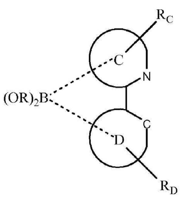
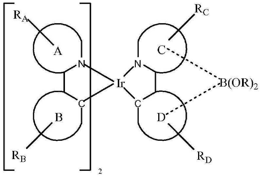
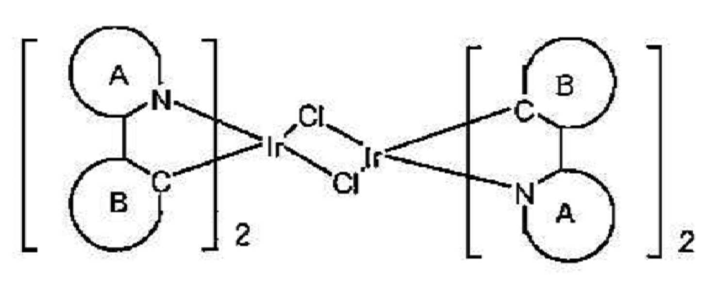
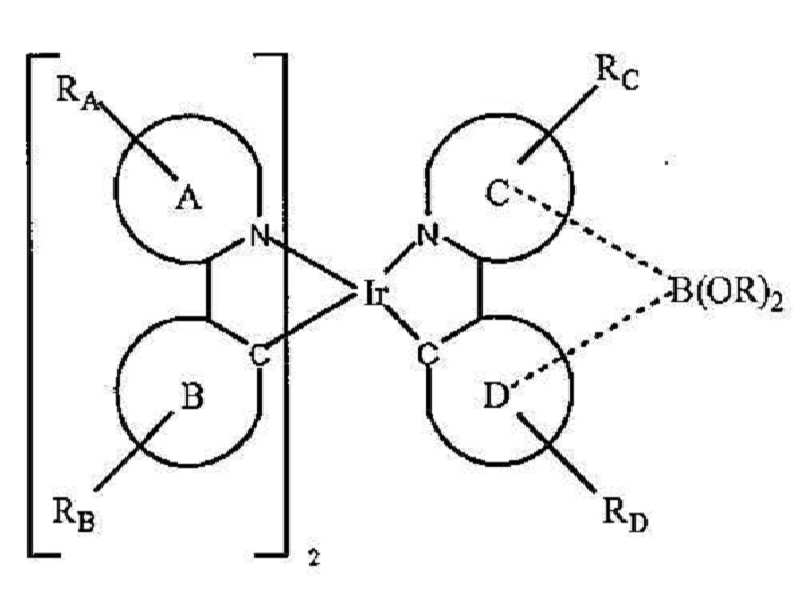
S는 중성 리간드이다. X는 카운터 이온이다. A 및 B는 각각 독립적으로 5원 또는 6원 방향족 또는 헤테로방향족 고리이고, A-B는 고리 A 상의 질소 원자 및 고리 B 상의 sp2 혼성화 탄소 원자를 통해 이리듐에 배위 결합된 방향족 또는 헤테로방향족 고리의 결합쌍을 나타낸다. C 및 D는 각각 독립적으로 5원 또는 6원 방향족 또는 헤테로방향족 고리이고, C-D는 고리 C 상의 질소 원자 및 고리 D 상의 sp2 혼성화 탄소 원자를 통해 이리듐에 배위 결합된 방향족 또는 헤테로방향족 고리의 결합쌍을 나타낸다. RA, RB, RC 및 RD는 각각 독립적으로 비치환, 알킬, 헤테로알킬, 아릴 또는 헤테로아릴 기로 구성된 군으로부터 선택된다. RA, RB, RC 및 RD 각각은 1 이상의 치환기를 나타낸다. R은 알킬, 헤테로알킬 또는 퍼플루오로알킬 기이고, 상기 2개의 R은 임의로 결합하여 고리를 형성한다.S is a neutral ligand. X is a counter ion. A and B are each independently a 5- or 6-membered aromatic or heteroaromatic ring, AB is a bonding pair of an aromatic or heteroaromatic ring coordinated to iridium via a nitrogen atom on ring A and an sp 2 hybridized carbon atom on ring B Indicates. C and D are each independently a 5- or 6-membered aromatic or heteroaromatic ring, and CD is a bonding pair of an aromatic or heteroaromatic ring coordinated to iridium via a nitrogen atom on ring C and an sp 2 hybridized carbon atom on ring D Indicates. R A , R B , R C and R D are each independently selected from the group consisting of unsubstituted, alkyl, heteroalkyl, aryl or heteroaryl groups. R A , R B , R C and R D each represent one or more substituents. R is an alkyl, heteroalkyl or perfluoroalkyl group, wherein the two R's optionally combine to form a ring.
상기 방법의 한 양태에서, 상기 카운터 이온 X는 트리플레이트, 토실레이트, 트리플루오로아세테이트, 테트라플루오로보레이트 및 헥사플루오로포스페이트로 구성된 군으로부터 선택된다.In one embodiment of the method, the counter ion X is selected from the group consisting of triflate, tosylate, trifluoroacetate, tetrafluoroborate and hexafluorophosphate.
한 양태에서, RA, RB, RC 및 RD 는 벤젠, 피리미딘, 피리딘, 티오펜, 티아나프텐, 불소, 카르바졸 및 디벤조티오펜으로 구성된 군으로부터 선택된다.In one embodiment, R A , R B , R C and R D are selected from the group consisting of benzene, pyrimidine, pyridine, thiophene, thianaphthene, fluorine, carbazole and dibenzothiophene.
또다른 양태에서, 상기 방법은In another embodiment, the method

상기 방법의 한 양태에서, 상기 B(OR)2 기는 고리 C에 결합한다. 또다른 양태에서, 상기 B(OR)2 기는 고리 D에 결합한다. 상기 방법의 특정 양태에서, 상기 B(OR)2 기는 
한 양태에서, 상기 방법은In one aspect, the method

한 양태에서, 상기 방법은In one aspect, the method

![]()


![]()
또다른 양태에서, 상기 방법은In another embodiment, the method


또다른 양태에서, 상기 방법은In another embodiment, the method


또다른 양태에서, 상기 방법은In another embodiment, the method


또다른 양태에서, 상기 방법은In another embodiment, the method


또다른 양태에서, 상기 방법은 
![]()

![]()
또한, 인광성 발광 화합물이 제공된다. 특히, 상기 화합물은 질소를 통해 상기 금속에 배위 결합한 이종환 고리 상에 연장된 컨쥬게이팅을 갖는 Ir(Ⅲ) 이종리간드성 착물이다. 상기 제공되는 화합물은 하기로 구성된 군으로부터 선택된 화학식을 가진다:In addition, a phosphorescent light emitting compound is provided. In particular, the compound is an Ir (III) heteroligand complex having extended conjugation on a heterocyclic ring coordinated to the metal via nitrogen. The provided compound has a formula selected from the group consisting of:
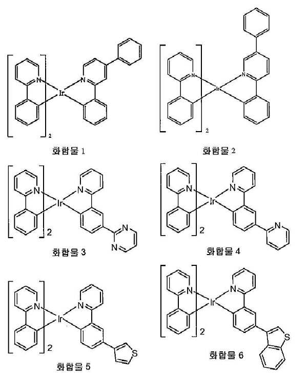
특정 화합물이 특히 이로울 수 있다. 한 양태에서, 바람직하게는 상기 화합물은 화합물 1이다. 또다른 양태에서, 바람직하게는 상기 화합물은 화합물 2이다.Certain compounds may be particularly beneficial. In one embodiment, preferably, the compound is Compound 1. In another embodiment, preferably, the compound is
이종리간드성 이리듐 화합물이 제공되며, 이는 유기 발광 소자에 이롭게 사용될 수 있다. 특히, 상기 화합물은 상기 소자의 발광 도판드로서 유용할 수 있다. 상기 리종리간드성 화합물은 하기로 구성된 군으로부터 선택된다:Heteroligand iridium compounds are provided, which can be advantageously used in organic light emitting devices. In particular, the compounds may be useful as light emitting dopants of the device. Said lipoligand compound is selected from the group consisting of:

특정 화합물이 특히 이로울 수 있다. 한 양태에서, 바람직하게는 상기 화합물이 화합물 8이다. 또다른 양태에서, 바람직하게는 상기 화합물은 화합물 9이다. 또다른 양태에서, 바람직하게는 상기 화합물은 화합물 10이다. 추가 양태에서, 바람직하게는 상기 화합물은 화합물 11이다. 또다른 양태에서, 바람직하게는 상기 화합물은 화합물 12이다. 추가 양태에서, 바람직하게는 상기 화합물은 화합물 13이다. 또다른 양태에서, 바람직하게는 상기 화합물은 화합물 14이다.Certain compounds may be particularly beneficial. In one embodiment, preferably, the compound is compound 8. In another embodiment, preferably, the compound is compound 9. In another embodiment, preferably, the compound is compound 10. In further embodiments, preferably, the compound is compound 11. In another embodiment, preferably, the compound is
또한, 유기 발광 소자가 제공되며, 상기 소자는 애노드, 캐소드, 및 그 애노드와 캐소드 사이에 배치된 유기층을 포함하고, 상기 유기층은 하기로 구성된 군으로부터 선택된 화합물을 추가로 포함한다.Also provided is an organic light emitting device, the device comprising an anode, a cathode, and an organic layer disposed between the anode and the cathode, the organic layer further comprising a compound selected from the group consisting of:

한 양태에서, 상기 소자의 유기층은 호스트를 추가로 포함한다. 화합물 1 및 2는 트리페닐렌기를 함유하는 호스트를 갖는 소자에서 특히 잘 작용하는 것으로 확인되었다. 특히, 상기 화합물은 상기 호스트가 화학식 
애노드, 캐소드, 및 그 애노드와 캐소드 사이에 배치된 유기층을 포함하는 유기 발광 소자가 제공된다. 상기 유기층은 하기로 구성된 군으로부터 선택된 화합물을 추가로 포함한다:An organic light emitting device is provided that includes an anode, a cathode, and an organic layer disposed between the anode and the cathode. The organic layer further comprises a compound selected from the group consisting of:

상기 소자의 유기층은 호스트를 추가로 포함할 수 있다. 화합물 7∼12는 트리페닐렌기를 함유하는 호스트를 갖는 소자에서 특히 잘 작용하는 것으로 확인되었다. 특히, 상기 화합물은 상기 호스트가, R이 아릴 또는 헤테로아릴인 화학식 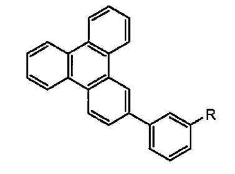
또한, 상기 소자를 포함하는 소비재가 또한 제공된다. 상기 소자는 애노드, 캐소드, 및 그 애노드와 캐소드 사이에 배치된 유기층을 추가로 포함한다. 상기 유기층은 화합물 1∼6으로부터 선택된 화합물을 함유한다.In addition, there is also provided a consumer goods comprising the device. The device further comprises an anode, a cathode, and an organic layer disposed between the anode and the cathode. The organic layer contains a compound selected from compounds 1-6.
애노드, 캐소드, 및 그 애노드와 캐소드 사이에 배치된 유기층을 추가로 포함하는 소자를 포함하는 소비재가 제공된다. 상기 유기층은 화합물 8∼14로 구성된 군으로부터 선택된 화합물을 추가로 포함한다.A consumer goods are provided comprising an anode, a cathode, and a device further comprising an organic layer disposed between the anode and the cathode. The organic layer further comprises a compound selected from the group consisting of compounds 8-14.
앞서 논의된 바와 같이, 이종리간드성 이리듐 착물의 제조를 위한 기존의 합성 방법은 많은 화합물의 생성에 현실적이지 않을 수 있다. 일반적으로 이용되는 한 합성 경로는 이리듐 트리플레이트 중간생성물을 유기 용매 중에서 제2 리간드와 반응시켜 이종리간드성 이리듐 착물을 생성하는 것을 포함한다.As discussed above, existing synthetic methods for the preparation of heteroligand iridium complexes may not be practical for the production of many compounds. One commonly used synthetic route involves reacting an iridium triflate intermediate with a second ligand in an organic solvent to produce a heteroleptic iridium complex.

그러나, 상기 방법은 흔히 상기 반응 중의 리간드 스크램블링에 의해 생성물들의 혼합물을 생성한다. 특히 상기 방법은 다양한 수율로 주생성물 및 부생성물을 발생시킨다. 생성물 화합물들의 혼합물은 소정의 생성물을 정제하는 데 문제를 유발시킬 수 있으며, 따라서 상기 방법의 실행 가능성을 한정할 수 있다.However, the method often produces a mixture of products by ligand scrambling during the reaction. In particular the method generates the main and by-products in various yields. Mixtures of product compounds can cause problems in purifying a given product, thus limiting the viability of the method.
물론, 본 원에서 제공되는 몇몇 이종리간드성 이리듐 화합물(즉, 화합물 10, 11 및 14)을, 알킬 치환된 트리플레이트 중간생성물(예를 들어, 6'-메틸페닐피리딘)이 사용되는 경우에 트리플레이트 중간생성물 합성을 이용하여 유의량의 오염 부생성물 없이 고수율로 발생시켰다. 화합물 10, 11 및 14의 합성 중 매우 낮은 정도의 리간드 스크램블링이 적어도 부분적으로도 기대되지 않았는데, 이는 화합물 11과 구조적으로 유사한 다른 화합물(예를 들어, 화합물 2)을 제조하는 데 이용하는 경우에 동일한 합성이 상기 동일한 결과를 제공하지 못했기 때문이다. 실시예 8 및 실험 부분을 참조할 수 있다.Of course, some heteroligand iridium compounds provided herein (ie, compounds 10, 11 and 14) may be triflate when alkyl substituted triflate intermediates (eg 6'-methylphenylpyridine) are used. Intermediate synthesis was used to generate high yields without significant amounts of contamination byproducts. Very low levels of ligand scrambling were not expected at least in part during the synthesis of compounds 10, 11 and 14, which was the same when used to prepare other compounds structurally similar to compound 11 (eg Compound 2). This is because it did not provide the same result. See Example 8 and the experimental part.
따라서, 연장된 컨쥬게이팅을 갖는 이종리간드성 화합물의 제조 방법이 본 원에서 제공된다(도 6에 예시됨). 상기 방법은 


바람직하게는, 상기 카운터 이온 X는 트리플레이트, 토실레이트, 트리플루오로보레이트 및 헥사플루오로포스페이트로 구성된 군으로부터 선택된다.Preferably, the counter ion X is selected from the group consisting of triflate, tosylate, trifluoroborate and hexafluorophosphate.
RA, RB, RC 및 RD는 바람직하게는 벤젠, 피리미딘, 피리딘, 티오펜, 티아나프텐, 불소, 카르바졸 및 디벤조티오펜으로 구성된 군으로부터 선택된다. 또한, Rz는 바람직하게는 알킬이고, 더욱 바람직하게는 Rz는 메틸이다.R A , R B , R C and R D are preferably selected from the group consisting of benzene, pyrimidine, pyridine, thiophene, thianaphthene, fluorine, carbazole and dibenzothiophene. In addition, Rz is preferably alkyl, more preferably Rz is methyl.
한 양태에서, 상기 방법은In one aspect, the method


바람직하게는, 상기 


상기 방법은, C-D 리간드와 반응하는 경우에 상기 반응 생성물의 유의적인 스크램블링 유도하지 않아 생성물을 정제하는 데 더욱 용이할 수 있는 상기 A-B로서, 페닐피리딘 대신에 알킬 치환된 페닐피리딘(예를 들어, 6-메틸페닐피리딘)을 포함한다. 특히, 전술한 방법은 화합물 10, 11 및14를 합성하는 데 사용되며, 스크램블링된 생성물로 매우 적게 오염된 고수율의 소정의 생성물을 나타낸다. 상기 반응 완결 후, 상기 반응 생성물을 크로마토그래피 분석하였다. 구체적으로는, 화합물 10, 11 및 14에 대한 주성분의 HPLC 백분율은 각각 99.4%, 99.4 및 99.4%로서 계산되었으나, 상기 부산물은 미정제된 침전 생성물 중 0.3%, 0.5% 및 0.5%의 HPLC 백분율로 배합되었다.한편, 기존의 트리플레이트 중간생성물 방법을 이용하여 이종리간드성 화합물을 제조하는 경우, 즉, LA-B의 위치가 비치환된 경우, 상기 생성물의 유의적인 스크램블링이 발생할 수 있다. 특히, 기존 방법을 이용한 화합물 2 및 7의 합성은 미정제된 반응 혼합물 중 주생성물 각각 92% 및 91%, 및 부생성물 각각 8% 및 9%를 제공하였다(HPLC에 의해 측정). 따라서, 전술한 알킬 치환된 페닐피리딘 리간드를 이용한 방법이 이종리간드성 화합물의 향상된 합성을 제공한다.The method is the AB, which may be easier to purify the product when inducing significant scrambling of the reaction product when reacted with a CD ligand, with alkyl substituted phenylpyridine (eg, 6 instead of phenylpyridine). -Methylphenylpyridine). In particular, the method described above is used to synthesize compounds 10, 11 and 14, and exhibits a high yield of a given product that is very contaminated with scrambled product. After completion of the reaction, the reaction product was chromatographed. Specifically, the HPLC percentages of principal components for compounds 10, 11 and 14 were calculated as 99.4%, 99.4 and 99.4%, respectively, but the by-products were obtained as HPLC percentages of 0.3%, 0.5% and 0.5% in the crude precipitate product. On the other hand, when the heteroligand compound is prepared using existing triflate intermediate methods, ie when the position of L AB is unsubstituted, significant scrambling of the product can occur. In particular, the synthesis of
추가로, 화학식 Ir(LA-B)2(LC-D)를 갖는 이종리간드성 화합물이 제공된다. LA-B는 


상기 리간드 LC-D는 바람직하게는 하기로 구성된 군으로부터 선택된다:The ligand L CD is preferably selected from the group consisting of:
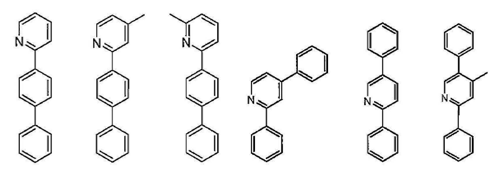
2-페닐피리딘 및 알킬 치환된 2-페닐피리딘 리간드는 이로운 특성을 제공할 수 있다. 구체적으로는, 이러한 리간드는 이리듐 (Ⅲ)과 강하게 결합한다. 따라서, 2-페닐피리딘 및 알킬 치환된 2-페닐피리딘은 우수한 화학적 안정성을 제공한다. 또한,이리듐 및 2-페닐피리딘 리간드의 트리스 착물은 저온(즉, < 250℃)의 고진공 하에서 증발한다. 그러나, 이러한 착물을 발광체로서 사용하는 PHOLED의 작동 안정성은 불량하며, 따라서 개선할 필요가 있다. 2-페닐피리딘 상의 아릴 치환이 소자 안정성을 향상시킬 수 있다. 불행하게도, 아릴 치환된 2-페닐피리딘의 트리스 이리듐 착물은 고온(즉, > 290℃)에서만 증발할 수 있다. 높은 증발 온도는 분해로 인해 장기간 제조에 바람직하지 않다. 따라서, 이러한 트리스 아릴 치환된 2-페닐피리딘을 PHOLED에 사용하는 것은 제한될 수 있다. 본 원에서 제공되는 상기 이종리간드성 화합물은 2개의 비치환된 2-페닐피리딘 리간드 또는 알킬 치환된 2-페닐피리딘 리간드, 및 하나의 아릴 치환된 2-페닐피리딘 리간드를 포함한다. 따라서, 본 원에서 제공되는 이종리간드성 화합물은 낮은 증발 온도를 제공하고 소자 작동 수명을 향상시킬 수 있다.2-phenylpyridine and alkyl substituted 2-phenylpyridine ligands can provide beneficial properties. Specifically, these ligands bind strongly with iridium (III). Thus, 2-phenylpyridine and alkyl substituted 2-phenylpyridine provide good chemical stability. Tris complexes of iridium and 2-phenylpyridine ligands also evaporate under high vacuum at low temperatures (ie, <250 ° C.). However, the operational stability of PHOLEDs using such complexes as light emitters is poor and therefore needs to be improved. Aryl substitution on 2-phenylpyridine can improve device stability. Unfortunately, the tris iridium complex of aryl substituted 2-phenylpyridine can only evaporate at high temperatures (ie> 290 ° C). High evaporation temperatures are undesirable for long term production due to decomposition. Thus, the use of such tris aryl substituted 2-phenylpyridine in PHOLED can be limited. Said heteroligand compounds provided herein include two unsubstituted 2-phenylpyridine ligands or alkyl substituted 2-phenylpyridine ligands, and one aryl substituted 2-phenylpyridine ligand. Thus, the heteroleptic compounds provided herein can provide low evaporation temperatures and improve device operating life.
구체적으로는, 2개의 2-페닐피리딘 리간드 및 하나의 2-(비페닐-3-일)피리딘 리간드를 갖는 화합물 7은 트리스(2-페닐피리딘)이리듐(Ⅲ)에 비해 PHOLED 중 향상된 안정성을 나타낸다. 화합물 7의 발광 스펙트럼은 약간 적색 이동하였다. 그러나, 상기 발광은 트리스(2-(비페닐-3-일)피리딘)이리듐(Ⅲ)에 비해 청색 이동하였다. 이와 함께, 이는 상기 둘 모두의 리간드, 즉, 2-페닐피리딘 및 2-(비페닐-3-일)피리딘은 아마도 상기 발광에 기여한다는 것을 제시한다. 또한, 화합물 7, 트리스(2-페닐피리딘)이리듐(Ⅲ), 및 트리스(2-(비페닐-3-일)피리딘)이리듐(Ⅲ)의 산화 및 환원 특성을 순환전류전압법(cyclic voltammetry)에 의해 측정하였으며, 상기 3개의 상이한 화합물에 대한 수치들 간에 유의적인 차이는 없었다. 따라서, 상기 화합물의 치환 패턴은 상기 착물의 HOMO 및 LUMO 수준을 유의적으로 이동시키지 않을 수 있다. Specifically, compound 7 with two 2-phenylpyridine ligands and one 2- (biphenyl-3-yl) pyridine ligand shows improved stability in PHOLEDs compared to tris (2-phenylpyridine) iridium (III) . The emission spectrum of Compound 7 shifted slightly red. However, the luminescence shifted blue compared to tris (2- (biphenyl-3-yl) pyridine) iridium (III). Together, this suggests that both ligands, ie 2-phenylpyridine and 2- (biphenyl-3-yl) pyridine, probably contribute to this luminescence. In addition, the oxidative and reduction characteristics of compound 7, tris (2-phenylpyridine) iridium (III), and tris (2- (biphenyl-3-yl) pyridine) iridium (III) were also measured by cyclic voltammetry. It was measured by, and there was no significant difference between the values for the three different compounds. Thus, the substitution pattern of the compound may not significantly shift HOMO and LUMO levels of the complex.
본 원에서 제공되는 이종리간드성 화합물 Ir(LA-B)2(LC-D)에서, 리간드 LA-B와 리간드 LC-D의 조합은 LUMO가 위치하는 피리딘 고리에 보다 우수한 컨쥬게이팅을 제공한다. 이론에 얽매임 없이, 상기 제공된 이종리간드성 화합물의 LUMO는 상기 컨쥬게이팅 결과로서 유의적으로 감소되고, 상기 피리딘 고리를 안정화시키는 것으로 생각된다. 동시에, 상기 발광 스펙트럼은 Ir(LC-D)3, 즉, 피리딘 상에 아릴을 갖는 트리스(2-페닐피리딘)이리듐 (Ⅲ)과 거의 동일하게 되었으며, 이는 발광이 LC-D에 의해 주도되는 동안 LA-B는 비발광 리간드임을 나타낸다. 본 원에서 개시되는 이종리간드성 화합물 Ir(LA-B)2(LC-D)는 높은 소자 안정성을 제공한다. 본 원에서 제공되는 이종리간드성 화합물 Ir(LA-B)(LC-D)2에서, 상기 효과는 유사하다.In the heteroligand compounds Ir (L AB ) 2 (L CD ) provided herein, the combination of ligand L AB and ligand L CD provides better conjugation to the pyridine ring in which LUMO is located. Without being bound by theory, it is believed that the LUMO of the heteroligand compound provided above is significantly reduced as a result of the conjugation and stabilizes the pyridine ring. At the same time, the emission spectrum became almost identical to Ir (L CD ) 3 , ie tris (2-phenylpyridine) iridium (III) with aryl on pyridine, which is L AB while luminescence is driven by L CD . Indicates a non-luminescent ligand. The heteroligand compounds Ir (L AB ) 2 (L CD ) disclosed herein provide high device stability. In the heteroligand compounds Ir (L AB ) (L CD ) 2 provided herein, the effect is similar.
앞선 단락에서 논의된 바와 같이, 이종리간드 Ir(Ⅲ) 착물의 합성은 보론산 에스테르 작용화된 에스테르가 이리듐 착물 중간생성물과 직접 반응하는 방법에 의해 향상될 수 있다. 상기 방법은 또한 도 4에 도시되어 있다. 구체적으로, 상기 합성은 상기 착물의 대규모 합성에 더욱 현실적일 수 있다. 상기 반응의 생성물은 칼럼 또는 기타 방법에 의해 분리할 수 있다. 또한, 상기 이종환 고리로부터의 연장된 컨쥬게이팅을 갖는 이종리리간드 Ir(Ⅲ) 착물은 본 원에서 기술된 방법에 따라 제조할 수 있다. 이러한 화합물이 또한 도 5에 도시되어 있다. 소자 중 상기 착물을 사용하여 소자 안정성 및 제작을 향상시킬 수 있다.As discussed in the preceding paragraph, the synthesis of heteroligand Ir (III) complexes can be enhanced by the method in which boronic ester functionalized esters react directly with iridium complex intermediates. The method is also shown in FIG. 4. Specifically, the synthesis may be more realistic for large scale synthesis of the complex. The product of the reaction can be separated by column or other method. In addition, heteroligand Ir (III) complexes with extended conjugation from the heterocyclic ring can be prepared according to the methods described herein. Such compounds are also shown in FIG. 5. The complexes in the device can be used to improve device stability and fabrication.
전술한 바와 같이, 이종리간드성 Ir(Ⅲ) 화합물의 합성은, 치환된 트리플레이트 이리듐 중간생성물이 제2 리간드와 반응하는 방법에 의해 향상될 수 있다. 상기 방법이 또한 도 6에 도시되어 있다. 구체적으로, 상기 합성은 상당히 감소된 리간드 스크램블링으로 인해 향상된 생성물 정제를 제공할 수 있다.As mentioned above, the synthesis of heteroligand Ir (III) compounds can be enhanced by the method in which substituted triflate iridium intermediates react with a second ligand. The method is also shown in FIG. 6. In particular, the synthesis can provide improved product purification due to significantly reduced ligand scrambling.
뒤틀린 아릴을 함유하는 1 이상의 리간드를 함유하는 신규한 화합물이 제공된다(도 7에 예시됨). 제공되는 특정 화합물은 뒤틀린 페닐 고리를 함유하는 Ir(2-페닐피리딘) 유형의 화합물을 포함한다(도 8에 예시됨). 이러한 뒤틀린 아릴 화합물은 향상된 효율, 안정성 및 제조를 제공하는 데 OLED에서 이롭게 사용될 수 있다. 바람직하게는, 이러한 화합물은 상기 소자에서 발광 도판트로서 사용될 수 있다.Novel compounds are provided containing one or more ligands containing warped aryl (illustrated in FIG. 7). Certain compounds provided include compounds of the Ir (2-phenylpyridine) type containing a twisted phenyl ring (illustrated in FIG. 8). Such warped aryl compounds can be advantageously used in OLEDs to provide improved efficiency, stability and manufacturing. Preferably, such compounds can be used as light emitting dopants in the device.
뒤틀린 아릴기를 함유하는 화합물이 문헌(예를 들어, US2007/0003789 및 US2009/0124805 참조)에 보고되어 있다.Compounds containing warped aryl groups have been reported in the literature (see eg US2007 / 0003789 and US2009 / 0124805).
2-페닐피리딘 및 알킬 치환된 2-페닐피리딘 리간드가 우수한 특성을 갖는 이리듐(Ⅲ) 화합물을 형성하는 반면에, 이러한 화합물은 소자에서의 실질적인 사용이 제한될 수 있다(예를 들어, 빈약한 작동 안정성). 2-페닐피리딘 상의 아릴 치환은 소자 효율을 향상시킬 수 있으나, 아릴 치환된 2-페닐피리딘의 트리스 이리듐 화합물은 고온(예를 들어, 290℃ 이상)에서만 증발하여, 상기 화합물의 용도도 제한할 수 있다(즉, 제조 중 분해). 특정 치환 패턴을 갖는 2-페닐피리딘 유형의 리간드가 특히 이로울 수 있다는 것이 확인되었다. 특히, 상기 2-페닐피리딘 유형의 리간드 상의 알킬 및 페닐 치환의 전략적인 조합은 평면으로부터 뒤틀리는 치환 아릴기(즉, 뒤틀린 아릴)를 유도하여, 팩킹을 감소시키고 증말 온도를 낮출 수 있다. 본 원에서 제공되는 화합물은, 치환기 아릴이 뒤틀린 아릴이 되도록 알킬 및 아릴 치환기를 갖는 1 이상의 리간드를 포함한다. 따라서, 이러한 화합물은 낮은 증발 온도를 제공하고, 소자 제조를 향상시키며, 소자 작동 수명을 향상시킬 수 있다.Whereas 2-phenylpyridine and alkyl substituted 2-phenylpyridine ligands form iridium (III) compounds with good properties, such compounds may have limited practical use in devices (eg poor operation). stability). Although aryl substitution on 2-phenylpyridine can improve device efficiency, tris iridium compounds of aryl substituted 2-phenylpyridine can only evaporate at high temperatures (eg, above 290 ° C.), thus limiting the use of these compounds. (Ie degradation during manufacture). It has been found that ligands of the 2-phenylpyridine type with certain substitution patterns can be particularly advantageous. In particular, strategic combinations of alkyl and phenyl substitutions on the 2-phenylpyridine type ligands can lead to substituted aryl groups (ie, warped aryl) that are twisted from the plane, thereby reducing packing and lowering the temperature of the vaporization. Compounds provided herein include one or more ligands having alkyl and aryl substituents such that the substituent aryl is twisted aryl. Thus, such compounds can provide low evaporation temperatures, improve device fabrication, and improve device operating life.
2-페닐피리딘 상에 치환된 아릴기는 또한 상기 리간드의 컨쥬게이팅을 증가시켜 적색 이동 발광을 유도할 수 있다. 상기 스펙트럼의 황색 부분의 장파장, 예컨대 540∼580 nm에서의 발광을 갖는 상기 화합물은 한정된 용도를 가질 수 있는데, 이는 그 발광이 상기 스펙트럼의 황색 부분에 한정되기 때문이다. 따라서, 상이한 범위, 예컨대 청색 이동 범위에서 발광하는 화합물이 바람직할 수 있다. 구체적으로, 약 521 ∼ 약 540 nm의 표적 에너지 범위에서 발광하는 화합물이 특히 바람직할 수 있다. 상기 치환기 아릴 고리가 알킬기 첨가에 의해 뒤틀린 화합물은 컨쥬게이팅이 한정되고, 청색 이동 발광을 나타낼 수 있다. 구체적으로, 본 원에서 제공되는 뒤틀린 아릴 화합물은 뒤틀리지 않은 아릴 치환기를 함유하는 상응하는 화합물에 비해 청색 이동하는 발광 에너지를 보유할 수 있다. 따라서, 이러한 청색 이동 화합물이 특히 바람직할 수 있다.An aryl group substituted on 2-phenylpyridine can also increase the conjugation of the ligand to induce red mobile luminescence. Such compounds having long wavelengths in the yellow portion of the spectrum, such as luminescence at 540-580 nm, may have limited use because the luminescence is limited to the yellow portion of the spectrum. Thus, compounds which emit light in different ranges, such as the blue shift range, may be preferred. Specifically, compounds that emit in the target energy range of about 521 to about 540 nm may be particularly preferred. The compound in which the substituent aryl ring is distorted by the addition of an alkyl group has limited conjugation and may exhibit blue shifted luminescence. Specifically, the warped aryl compounds provided herein can have blue shifted luminescence energy compared to corresponding compounds containing untwisted aryl substituents. Thus, such blue shifting compounds may be particularly preferred.
뒤틀린 아릴을 갖는 1 이상의 리간드를 함유하는 화합물이 제공된다. 발광성 리간드에 대한 상이한 뒤틀린 아릴 치환 패턴의 효과를 연구하여 치환된 Ir(2-페닐피리딘) 유형의 인광성 물질 및 이러한 물질을 함유하는 소자에 대한 구조-특성 관계를 수립하였다. 뒤틀린 페닐을 함유하는 화합물을 이용하는 PHOLED의 소자 특성뿐만 아니라, 증발 온도, 증발 안정성 및 용해도를 비롯한 물질 가공성의 몇몇 양태를 연구하였다. 상기 화합물에 존재하는, 전략적으로 위치하는 치환기는 치환기 아릴 고리의 뒤틀림을 유도할 수 있다. 상기 아릴기(즉, 고리 C) 또는 상기 뒤틀린 아릴에 인접하는 피리딘 고리(즉, 고리 A) 상에 존재하는 치환기는 상기 아릴기의 추가적인 뒤틀림을 유도할 수 있다. 결과적으로, 뒤틀림 아릴 부분을 갖는 화합물은 (i) 감소된 컨쥬게이팅, 따라서 일반적으로 컨쥬게이팅 증가(즉, 페닐의 첨가)와 관련이 있는 적색 이동 효과의 최소화, (ⅱ) 스태킹(stacking) 감소, 따라서 증발 온도 감소 및 장기 열안정성 및 가공성 증가, 및 (ⅲ) 좁은 발광, 따라서 높은 발광 효율(즉, 높은 LE:EQE)의 유도를 제공할 수 있다.Compounds are provided that contain one or more ligands with twisted aryl. The effects of different twisted aryl substitution patterns on luminescent ligands were studied to establish structure-characteristic relationships for substituted Ir (2-phenylpyridine) type phosphorescent materials and devices containing these materials. Several aspects of material processability, including evaporation temperature, evaporation stability and solubility, as well as device properties of PHOLEDs using compounds containing warped phenyl have been studied. Strategically located substituents present in the compound may lead to distortion of the substituent aryl ring. Substituents on the aryl group (ie, ring C) or on the pyridine ring (ie, ring A) adjacent to the warped aryl can lead to further distortion of the aryl group. As a result, compounds with warped aryl moieties may (i) minimize the effect of red shifting associated with reduced conjugation, thus increasing conjugation (ie, the addition of phenyl), (ii) reducing stacking, It can thus provide a reduction in evaporation temperature and an increase in long term thermal stability and processability, and (i) induction of narrow luminescence, thus high luminescence efficiency (ie high LE: EQE).
뒤틀린 아릴 및 한정된 수의 치환기(예를 들어, 단일 치환기)를 함유하는 화합물은 향상된 안정성을 제공할 수 있는 동시에, 뒤틀린 아릴의 이점, 예컨대 향상된 효율 및 제조를 유지한다. 또한, 본 원에서 제공되는 특정 화합물은 특히 좁은 발광을 나타내어, 기타 공지된 향상 이외에도 특히 우수한 발광 효율을 갖는 소자를 제공할 수 있다. 따라서, 본 원에서 제공된 화합물이 특히 바람직할 수 있다.Compounds containing warped aryl and a limited number of substituents (eg, single substituents) can provide improved stability while maintaining the benefits of warped aryl, such as improved efficiency and manufacturing. In addition, certain compounds provided herein exhibit particularly narrow luminescence, thereby providing devices having particularly good luminous efficiency in addition to other known improvements. Thus, the compounds provided herein may be particularly preferred.
이론에 얽매임 없이, 치환기 아릴 중에 뒤틀림을 유도하는 단 하나의 치환기를 갖는 화합물이 특히 이로울 수 있을 것으로 생각된다. 특히, 아릴 치환기의 뒤틀림을 유도하는 단일 치환기를 갖는 화합물은 다중 치환기를 함유하는 상응하는 화합물보다 더욱 안정적일 수 있다. 평면으로부터의 뒤틀림 정도가 보다 높을 수 있는 다중 치환기를 갖는 화합물에 비해, 단일 치환기를 갖는 화합물은 치환기 아릴과 상기 리간드의 나머지 사이의 뒤틀림 정도가 더욱 적어, 컨쥬게이팅이 더욱 많을 수 있는 것으로 생각된다. 특히, 단일 메틸 치환기를 갖는 화합물은 다중 메틸 치환기를 갖는 화합물에 비해 향상된 안정성을 보유할 수 있다. 예를 들어, 소자예 28 및 비교 소자예 6은, 소자예 28이 발광 도판트로서 화합물 35을 사용하는 반면, 비교 소자예 6은 발광 도판트로서 E4를 사용한다는 것을 제외하고 동일한 소자 구조 및 조성을 가진다. 화합물 35 및 E4 둘 모두는 2-페닐피리딘의 5번 위치에 결합된 뒤틀린 아릴기를 갖는 리간드를 갖는 트리스 동종리간드성 화합물(즉, IrL3)이다. 이의 유일한 차이점은, 화합물 35에서 아릴이 2-메틸페닐기인 반면에, E4에서는 아릴이 2,5-디메틸페닐이라는 점이다.Without being bound by theory, it is contemplated that compounds having only one substituent inducing distortion in the substituent aryl may be particularly advantageous. In particular, compounds having a single substituent that induces distortion of the aryl substituents may be more stable than corresponding compounds containing multiple substituents. Compared with compounds having multiple substituents, which may have a higher degree of distortion from the plane, it is contemplated that compounds having a single substituent may have less distortion between the substituent aryl and the remainder of the ligand, thus allowing more conjugation. In particular, compounds having a single methyl substituent can have improved stability compared to compounds having multiple methyl substituents. For example, Device Example 28 and Comparative Device Example 6 show the same device structure and composition except that Device Example 28 uses Compound 35 as the light emitting dopant, while Comparative Device Example 6 uses E4 as the light emitting dopant. Have Compounds 35 and E4 are both tris homoligand compounds (ie IrL 3 ) having ligands with twisted aryl groups bonded at position 5 of 2-phenylpyridine. The only difference is that in compound 35 the aryl is a 2-methylphenyl group while in E4 the aryl is 2,5-dimethylphenyl.

E4에서의 여분의 메틸기는 화합물 35에서보다 상기 뒤틀린 아릴을 더욱 뒤틀리게 한다. 상기 결과(표 8)는 화합물 35를 갖는 소자(소자예 28, RT80% = 200 h)가 E4를 갖는 소자(비교 소자예 6, RT80% = 42 h)보다 더욱더 안정하다는 것을 나타낸다. 더욱 컨쥬게이팅된 리간드가 더욱 안정한 발광 도판트를 유도할 수 있는 것으로 생각된다. 일련의 E3, 화합물 35 및 E4에서의 컨쥬게이팅은 메틸기의 수가 0에서 1로, 2로 증가함에 따라(즉, 피리딘과 C 고리 사이의 뒤트림 증가) 감소한다. 따라서, 발광 도판트로서 E3를 갖는 소자가 발광 도판트로서 화합물 35를 갖는 소자보다 더욱 안정할 수 있는 것으로 생각하는 것은 합당하다. 그러나, 컨쥬게이팅의 증가는 또한 상응하는 Ir 착물의 발광에서의 적색 이동을 유도할 수 있다. 표7은 E3(비교 소자예 5)가 548 nm의 λmax 및 (0.430, 0.560) CIE를 갖는 반면, 화합물 35(소자예 28)가 532 nm의 λmax 및 (0.368, 0.607)의 CIE를 갖고, E4 (비교 소자예 6)가 520 nm의 λmax 및 (0.320, 0.632)의 CIE를 갖는다는 것을 나타낸다. 따라서, E3가 더욱 안정할 수 있지만, 상기 발광은 충분한 RGB 컬러 디스플레이에 적합하지 않은 황색이다. 화합물 35는 E3과 E4 사이에 컨쥬게이팅을 가져, E4(컨쥬게이팅 거의 없음)에 대한 더욱 향상된 안정성 및 E3(컨쥬게이팅 너무 많음)에 대한 보다 녹색의 색을 달성할 수 있다.The extra methyl group in E4 makes the warped aryl more warped than in compound 35. The results (Table 8) show that the device with compound 35 (Device Example 28, RT 80% = 200 h) is more stable than the device with E4 (Comparative Device Example 6, RT 80% = 42 h). It is believed that more conjugated ligands can induce more stable luminescent dopants. Conjugation in the series of E3, Compounds 35 and E4 decreases as the number of methyl groups increases from 0 to 1, 2 (ie, increased distortion between pyridine and the C ring). Therefore, it is reasonable to think that devices having E3 as light emitting dopants may be more stable than devices having compound 35 as light emitting dopants. However, an increase in conjugation can also lead to a red shift in the emission of the corresponding Ir complex. Table 7 shows that E3 (Comparative Device Example 5) has a λ max and (0.430, 0.560) CIE of 548 nm, while Compound 35 (Device Example 28) has a λ max of 532 nm and a CIE of (0.368, 0.607). , E4 (Comparative Device Example 6) has a λ max of 520 nm and a CIE of (0.320, 0.632). Thus, E3 may be more stable, but the light emission is yellow, which is not suitable for a sufficient RGB color display. Compound 35 may have conjugation between E3 and E4 to achieve better stability for E4 (almost no conjugation) and a greener color for E3 (too much conjugating).
치환기 아릴이 뒤틀리고 하기 구조를 갖도록 알킬 치환기 및 아릴 치환기를 갖는 리간드 L을 포함하는 화합물이 제공된다:Compounds are provided comprising a ligand L having an alkyl substituent and an aryl substituent such that the substituent aryl is distorted and has the structure:

B 및 C는 각각 독립적으로 5원 또는 6원 탄소환 또는 이종환 고리이다. A-B는 고리 A 중의 질소 원자 및 고리 B 중의 sp2 혼성화 탄소 원자를 통해 금속 M에 배위 결합된 탄소환 또는 이종환 고리의 결합쌍을 나타낸다. A-C는 탄소환 및 이종환 고리의 결합쌍을 나타낸다. Ra, Rb 및 Rc는 모노, 디, 트리 또는 테트라 치환을 나타낼 수 있다. Ra, Rb 및 Rc는 독립적으로 수소, 알킬, 알콕시, 아미노, 알케닐, 알키닐, 아릴킬, 아릴 및 헤테로아릴로 구성된 군으로부터 선택된다. X1, X2, X3, X4, X5, X6, X7, X8 및 X9는 독립적으로 탄소 및 질소로부터 선택된다. 바람직하게는, A는 피리딘이다. R1 및 R2는 독립적으로 수소, 알킬, 알콕시, 아미노, 알케닐, 알키닐, 아릴킬, 아릴 및 헤테로아릴로 구성된 군으로부터 선택된다. C에 인접한 R1, R2 및 Ra 치환기들 중 1 이상은 수소가 아니다. 바람직하게는, C에 인접한 R1, R2 및 Ra 치환기들 중 하나만이 수소가 아니다. 바람직하게는, C에 인접한 R1, R2 및 Ra 치환기들 중 하나만이 알킬이다. 더욱 바람직하게는, C에 인접한 R1, R2 및 Ra 치환기들 중 하나만이 에틸이다. 가장 바람직하게는, C에 인접한 R1, R2 및 Ra 치환기들 중 하나만이 메틸이다. 상기 리간드 L은 원자 번호가 40보다 큰 금속 M에 배위 결합된다. 바람직하게는, 상기 금속 M은 Ir이다.B and C are each independently a 5- or 6-membered carbocyclic ring or a heterocyclic ring. AB represents a bonding pair of carbocyclic or heterocyclic rings coordinated to metal M via a nitrogen atom in ring A and an sp 2 hybridized carbon atom in ring B. AC represents a bonding pair of carbocyclic and heterocyclic rings. R a , R b and R c may represent mono, di, tri or tetra substitutions. R a , R b and R c are independently selected from the group consisting of hydrogen, alkyl, alkoxy, amino, alkenyl, alkynyl, arylalkyl, aryl and heteroaryl. X 1 , X 2 , X 3 , X 4 , X 5 , X 6 , X 7 , X 8 and X 9 are independently selected from carbon and nitrogen. Preferably, A is pyridine. R 1 and R 2 are independently selected from the group consisting of hydrogen, alkyl, alkoxy, amino, alkenyl, alkynyl, arylalkyl, aryl and heteroaryl. At least one of the R 1 , R 2 and R a substituents adjacent to C is not hydrogen. Preferably, only one of the R 1 , R 2 and R a substituents adjacent to C is not hydrogen. Preferably, only one of the R 1 , R 2 and R a substituents adjacent to C is alkyl. More preferably, only one of the R 1 , R 2 and R a substituents adjacent to C is ethyl. Most preferably, only one of the R 1 , R 2 and R a substituents adjacent to C is methyl. The ligand L is coordinately bonded to the metal M having an atomic number greater than 40. Preferably, the metal M is Ir.
하기 구조를 갖는 특정 화합물이 제공된다:Certain compounds are provided having the following structures:

m은 상기 금속 M의 산화수이다. n은 1 이상이다. L'은 1가 음이온성의 2자리 리간드이다. 바람직하게는, C에 인접한 R1, R2 및 Ra 치환기들 중 하나만이 수소가 아니다. 바람직하게는, C에 인접한 R1, R2 및 Ra 치환기들 중 하나만이 알킬이다. 더욱 바람직하게는, C에 인접한 R1, R2 및 Ra 치환기들 중 하나만이 에틸이다. 가장 바람직하게는, C에 인접한 R1, R2 및 Ra 치환기들 중 하나만이 메틸이다. 바람직하게는, A는 피리딘이다.m is the oxidation number of the said metal M. n is 1 or more. L 'is a monovalent anionic bidentate ligand. Preferably, only one of the R 1 , R 2 and R a substituents adjacent to C is not hydrogen. Preferably, only one of the R 1 , R 2 and R a substituents adjacent to C is alkyl. More preferably, only one of the R 1 , R 2 and R a substituents adjacent to C is ethyl. Most preferably, only one of the R 1 , R 2 and R a substituents adjacent to C is methyl. Preferably, A is pyridine.
화학식 (Ⅱ)를 갖는 화합물의 특정 예가 제공된다. 상기 화합물은 하기 화합물들로 구성된 군으로부터 선택된다:Specific examples of compounds having Formula (II) are provided. The compound is selected from the group consisting of the following compounds:

R은 수소가 아니다. 바람직하게는, R은 알킬이다.R is not hydrogen. Preferably, R is alkyl.
화학식 (Ⅱ)를 갖는 화합물의 특정 예가 제공된다. 한 양태에서, 상기 화합물은 하기 화합물들로 구성된 군으로부터 선택된다:Specific examples of compounds having Formula (II) are provided. In one embodiment, the compound is selected from the group consisting of:


바람직하게는, 상기 화합물은 화합물 21 , 화합물 22, 화합물 25, 화합물 29, 화합물 30, 화합물 31 및 화합물 34로 구성된 군으로부터 선택된다.Preferably, the compound is selected from the group consisting of
한 양태에서, 하기로 구성된 군으로부터 선택된 화합물이 제공된다:In one embodiment there is provided a compound selected from the group consisting of:

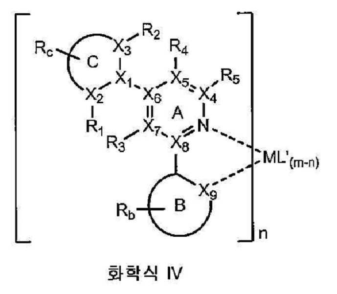
R1, R2, R3 및 R4 중 1 이상이 수소가 아니다. R5는 수소, 알킬, 알콕시, 아미노, 알케닐, 알키닐, 아릴킬, 아릴 및 헤테로아릴로 구성된 군으로부터 선택된다.At least one of R 1 , R 2 , R 3 and R 4 is not hydrogen. R 5 is selected from the group consisting of hydrogen, alkyl, alkoxy, amino, alkenyl, alkynyl, arylalkyl, aryl and heteroaryl.
전술한 바와 같이, 상기 치환기 아릴 고리(즉, C 고리)에 인접한 뒤틀림 유도 치환기의 위치는 평면으로부터의 C 고리의 뒤트림을 유도하여, 팩킹을 감소시키고, 증발 온도, 용해도, 에너지 수준, 소자 효율 및 발광 스펙트럼의 좁음과 관련하여 광범위한 조절가능성을 제공한다. 또한, 상기 치환기는 소자 작동에서도 화학적으로 안정한 작용기일 수 있다.As noted above, the position of the distortion induced substituent adjacent to the substituent aryl ring (ie, C ring) induces distortion of the C ring from the plane, reducing packing, evaporation temperature, solubility, energy level, device efficiency And with regard to the narrowness of the emission spectrum. In addition, the substituent may be a chemically stable functional group even in the operation of the device.
한 양태에서, R1 및 R2는 수소이고, R3 및 R4 중 하나는 알킬이다. 예시적 화합물로는 화합물s 21∼24 및 29∼34, 36 및 37을 들 수 있다. 또다른 양태에서, R1 및 R2 중 하나는 알킬이고, R3 및 R4는 수소이다. 예시적 화합물로는 화합물 25∼28 및 35을 들 수 있다.In one embodiment, R 1 and R 2 are hydrogen and one of R 3 and R 4 is alkyl. Exemplary compounds include compounds 21-24 and 29-34, 36 and 37. In another embodiment, one of R 1 and R 2 is alkyl and R 3 and R 4 are hydrogen. Exemplary compounds include compounds 25-28 and 35.
또다른 양태에서, 상기 화합물은 하기 화학식의 화합물로 구성된 군으로부터 선택된다: In another embodiment, the compound is selected from the group consisting of compounds of the formula:


화학식 (Ⅱ)를 갖는 화합물로는 동종리간드성 화합물 및 이종리간드성 화합물을 들 수 있다. 동종리간드성 화합물의 비한정적인 예로는 화합물 21∼24 및 35를 들 수 있다. 이종리간드성 화합물의 비한정적인 예로는 화합물 25∼34, 36 및 37을 들 수 있다.As a compound which has Formula (II), a homoligand compound and a heteroligand compound are mentioned. Non-limiting examples of homoleptic compounds include compounds 21-24 and 35. Non-limiting examples of heteroligands include compounds 25-34, 36, and 37.
하기로 구성된 군으로부터 선택되는 리간드 L'을 갖는 특정 이종리간드성 화합물이 제공된다:Certain heteroligand compounds are provided having a ligand L 'selected from the group consisting of:
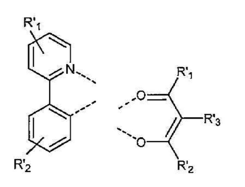
R'1, R'2 및 R'3는 독립적으로 수소, 알킬, 알콕시, 아미노, 알케닐, 알키닐, 아릴킬, 아릴 및 헤테로아릴로 구성된 군으로부터 선택된다.R ' 1 , R' 2 and R ' 3 are independently selected from the group consisting of hydrogen, alkyl, alkoxy, amino, alkenyl, alkynyl, arylalkyl, aryl and heteroaryl.
아릴 치환기를 또한 갖는 2-페닐피리딘 리간드의 피리딘 고리 상에 존재하는 알킬 치환기를 갖는, 뒤틀린 아릴 함유 화합물이 바람직할 수 있다. 특히, 화합물 21 ∼ 화합물 23, 화합물 29 ∼ 화합물 31, 화합물 34, 화합물 36 및 화합물 37로 구성된 군으로부터 선택되는 바람직한 화합물이 제공된다. 더욱더 바람직한 화합물로는 2-페닐피리딘 리간드의 4번 위치(즉, 피리딘 질소에 대한 파라 위치)에 알킬기를 갖는 화합물 21, 화합물 22, 화합물 29-31, 화합물 34, 화합물 36 및 화합물 37이 있다. 이는, 이러한 치환이 상기 뒤틀림, 및 또한 약간의 청색 이동 효과를 제공할 수 있어 상기 화합물이 보다 진한 녹색 발광을 내게 할 수 있기 때문이다. 예를 들어, 소자예 13는 525 nm의 λmax 및 (0.342, 0.612)의 CIE를 갖는 반면에, 소자예 19는 532 nm의 λmax 및 (0.372, 0.599)의 CIE를 가진다. 실시예 13은 상기 2-페닐피리딘 리간드의 4번 위치에 메틸기를 갖는 발광 도판트로서 화합물 12를 사용하는 반면에, 실시예 19는 뒤틀린 페닐의 2번 위치에 메틸기를 갖는 발광 도판트로서 화합물 25를 사용한다. 상기 둘 모두의 경우에서 구조적으로 유도된 뒤틀림은 유사한 것으로 생각되지만, 상기 피리딘 질소에 대한 파라 위치에 있는 메틸은 전자 공여 효과를 제공하여, 착물의 LUMO 에너지 수준 및 또한 트리플렛 에너지을 상승시켜 발광에서의 청색 이동을 유도한다.Twisted aryl containing compounds with alkyl substituents present on the pyridine ring of the 2-phenylpyridine ligand also having aryl substituents may be preferred. In particular, preferred compounds selected from the group consisting of Compounds 21-23, Compounds 29-31, Compounds 34, 36 and 37 are provided. Even more preferred compounds include
유기 발광 소자가 또한 제공된다. 상기 소자는 애노드, 캐소드, 및 그 애노드와 캐소드 사이에 배치된 유기층을 가지며, 여기서 그 유기층은 전술한 화학식 (I)을 갖는 화합물을 포함한다. 화학식 (I)을 갖는 화합물에 바람직한 것으로 기술된 치환기에 대한 선택 사항은 또한 화학식 (I)의 화합물을 포함하는 소자에 적용하는 데 또한 바람직하다. 이러한 선택 사항은 금속 M; 화학식 Ⅱ∼Ⅳ; C에 인접한 R, R1, R2 및 Ra 치환기; 고리 C의 위치; 및 고리 A, B 및 C에 대해서 기술된 것을 포함한다.An organic light emitting element is also provided. The device has an anode, a cathode, and an organic layer disposed between the anode and the cathode, wherein the organic layer comprises a compound having the formula (I) described above. Options for substituents described as being preferred for compounds having formula (I) are also preferred for application to devices comprising compounds of formula (I). These options include metal M; Formulas II to IV; R, R 1 , R 2 and R a substituents adjacent to C; Position of ring C; And those described for rings A, B, and C.
한 양태에서, 상기 소자는 전술한 바와 같은 화학식 (Ⅱ)를 갖는 화합물을 포함한다. 바람직하게는, 상기 금속 M은 Ir이다. 바람직하게는, A는 피리딘이다. 또다른 양태에서, 상기 소자는 전술한 바와 같은 화학식 (Ⅲ) 또는 화학식 (Ⅳ)를 갖는 화합물을 포함한다. C에 인접한 R1, R2 및 Ra 치환기들 중 하나만이 알킬인 화합물을 함유하는 소자가 또한 바람직할 수 있다. 또다른 양태에서, 상기 소자는 전술한 화학식 (V) 또는 화학식 (Ⅵ)의 화합물을 포함한다. 화합물 21 ∼ 화합물 37로 구성된 군으로부터 선택된 화합물을 함유하는 특정 소자가 제공된다. 바람직하게는, 상기 소자는 화합물 21, 화합물 22, 화합물 25, 화합물 29, 화합물 30, 화합물 31 또는 화합물 34를 함유한다.In one embodiment, the device comprises a compound having formula (II) as described above. Preferably, the metal M is Ir. Preferably, A is pyridine. In another embodiment, the device comprises a compound having formula (III) or formula (IV) as described above. Also preferred are devices containing compounds in which only one of the R 1 , R 2 and R a substituents adjacent to C is alkyl. In another embodiment, the device comprises a compound of formula (V) or formula (VI) as described above. There is provided a specific device containing a compound selected from the group consisting of Compounds 21-37. Preferably, the device contains
한 양태에서, 유기층이 발광층이고 화학식 (I)을 갖는 화합물이 발광 도판트인 소자가 제공된다. 더욱이, 상기 유기층은 호스트를 추가로 포함할 수 있다. 바람직하게는 상기 호스트는 하기 화학식을 가진다:In one aspect, there is provided a device wherein the organic layer is a light emitting layer and the compound having formula (I) is a light emitting dopant. Moreover, the organic layer may further comprise a host. Preferably the host has the formula:

R'1, R'2, R'3, R'4, R'5 및 R'6는 독립적으로 수소, 알킬, 알콕시, 아미노, 알케닐, 알키닐, 아릴킬, 아릴 및 헤테로아릴로 구성된 군으로부터 선택된다.R ' 1 , R' 2 , R ' 3 , R' 4 , R ' 5 and R' 6 are independently a group consisting of hydrogen, alkyl, alkoxy, amino, alkenyl, alkynyl, arylalkyl, aryl and heteroaryl Is selected from.
소자를 포함하는 소비재가 또한 제공된다. 상기 소자는 애노드, 캐소드, 및 그 애노드와 캐소드 사이에 배치된 유기층을 포함하며, 여기서 상기 유기층은 전술한 바와 같은 화학식 (I)의 화합물을 포함한다. 화학식 (I)을 갖는 화합물에 바람직한 것으로 기술된 치환기에 대한 선택 사항은 또한 화학식 (I)을 갖는 화합물을 포함하는 소자를 함유하는 소비재에 적용하는 데 또한 바람직하다. 이러한 선택 사항은 금속 M; 화학식 Ⅱ∼Ⅳ; C에 인접한 R, R1, R2 및 Ra 치환기; 고리 C의 위치; 및 고리 A, B 및 C에 대해서 기술된 것을 포함한다.Consumer goods comprising the device are also provided. The device comprises an anode, a cathode, and an organic layer disposed between the anode and the cathode, wherein the organic layer comprises a compound of formula (I) as described above. The options for substituents described as being preferred for compounds having formula (I) are also preferred for application to consumer products containing devices comprising compounds having formula (I). These options include metal M; Formulas II to IV; R, R 1 , R 2 and R a substituents adjacent to C; Position of ring C; And those described for rings A, B, and C.
또한, 동종리간드성 Ir(Ⅲ) 화합물의 신규한 제조 방법이 제공된다(도 9에 예시됨). 동종리간드성 Ir(Ⅲ) 화합물을 제조하는 데 일반적으로 이용되는 방법은 상기 리간드와 Ir(acac)3의 혼합물을 환류 글리세롤(∼180℃)에 의해 또는 >230℃의 용매 없이 가열하는 것을 포함한다. 이러한 높은 반응 온도는 상기 리간드 및 생성된 착물의 열분해와 같은 문제를 야기시킬 수 있다. 따라서, 저온에서 동종리간드성 Ir(Ⅲ) 화합물을 제조하는 신규한 방법을 제공하는 것이 매우 바람직하다. 본 원에서 기술된 바와 같은 상기 방법을 이용하여 OLED에서 이롭게 사용할 수 있는 동종리간드성 Ir(Ⅲ) 화합물을 제조할 수 있다. 특히, 동종리간드성 Ir(Ⅲ) 화합물의 제1 제조 방법이 제공된다. 제1 방법을 이용하여 상기 리간드의 이종리간드 고리에, 질소에 인접하지 않은 알킬기를 갖는 화합물을 합성할 수 있다. 예를 들어, 화합물 21, 22 및 24는 제공된 제1 방법을 이용하여 합성할 수 있다. 동종리간드성 Ir(Ⅲ) 화합물의 제2 제조 방법이 또한 제공된다. 제2 방법을 이용하여 상기 리간드의 이종환 고리에, 질소에 인접하는 알킬기를 갖는 화합물을 제조할 수 있다. 화합물 23은, 예를 들어 제공되는 제2 방법을 이용하여 합성할 수 있다.Also provided is a novel process for preparing homoligand Ir (III) compounds (illustrated in FIG. 9). Commonly used methods for preparing homoligand Ir (III) compounds include heating the mixture of ligand and Ir (acac) 3 with reflux glycerol (˜180 ° C.) or without solvent at> 230 ° C. . Such high reaction temperatures can cause problems such as pyrolysis of the ligands and the resulting complexes. Therefore, it is highly desirable to provide a novel process for preparing homoligand Ir (III) compounds at low temperatures. The method as described herein can be used to prepare homoligand Ir (III) compounds that can be advantageously used in OLEDs. In particular, a first method for producing a homoligand Ir (III) compound is provided. Using the first method, a compound having an alkyl group not adjacent to nitrogen can be synthesized in the heteroligand ring of the ligand. For example, compounds 21, 22 and 24 can be synthesized using the first method provided. Also provided is a second method for preparing homoligand Ir (III) compounds. Using the second method, a compound having an alkyl group adjacent to nitrogen can be prepared in the heterocyclic ring of the ligand. Compound 23 can be synthesized using, for example, the second method provided.
동종리간드성 Ir(Ⅲ) 착물의 제1 제조 방법이 제공된다. 제1 방법은A first method for producing a homoligand Ir (III) complex is provided. The first way is
저비점 알콜의 존재 하에 

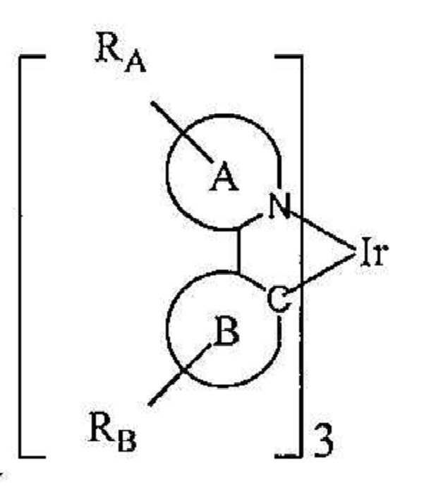
RA 및 RB 중 1 이상은 알킬기이고, 상기 알킬기는 피리딘 고리 상의 질소에 인접하지 않는다. S는 중성 리간드이다. X는 카운터 이온이다. 바람직하게는, X는 트리플레이트이다. A 및 B는 각각 독립적으로 5원 또는 6원 탄소환 또는 이종환 고리이다. A-B는 고리 A 상의 질소 원자 및 고리 B 상의 sp2 혼성화 탄소 원자를 통해 이리듐에 배위 결합된 탄소환 또는 이종환 고리이 결합쌍을 나타낸다. RA 및 RB 각각은 모노, 디, 트리 또는 테트라 치환을 나타낼 수 있다. RA 및 RB는 각각 독립적으로 수소, 알킬, 알콕시, 아미노, 알케닐, 알키닐, 아릴킬, 아릴 및 헤테로아릴로 구성된 군으로부터 선택된다.At least one of R A and R B is an alkyl group, which is not adjacent to the nitrogen on the pyridine ring. S is a neutral ligand. X is a counter ion. Preferably, X is triflate. A and B are each independently a 5- or 6-membered carbocyclic ring or a heterocyclic ring. AB represents a bond pair of a carbocyclic ring or heterocyclic ring coordinated to iridium via a nitrogen atom on ring A and an sp 2 hybridized carbon atom on ring B. Each of R A and R B may represent mono, di, tri or tetra substitutions. R A and R B are each independently selected from the group consisting of hydrogen, alkyl, alkoxy, amino, alkenyl, alkynyl, arylalkyl, aryl and heteroaryl.
저비점 알콜은 비등 온도가 108℃ 이하인 임의의 알콜을 포함할 수 있다. 한 양태에서, 상기 저비점 알콜은 메탄올, 에탄올, n-프로판올, 이소프로판올, n-부탄올, 1:1 비율의 에탄올과 메탄올, 2-메톡시에탄올 및 2-에톡시에탄올로 구성된 군으로부터 선택된다. 바람직하게는, 상기 저비점 알콜은 108℃에서 비등하는 이소프로판올, 78℃에서 비등하는 에탄올, 및 64∼78℃에서 비등하는 1:1 비율의 에탄올과 메탄올로 구성된 군으로부터 선택된다. 더욱 바람직하게는, 상기 저비점 알콜은 에탄올 또는 1:1 비율의 에탄올과 메탄올이다. 가장 바람직하게는, 상기 저비점 알콜은 1:1 비율의 에탄올과 메탄올이다Low boiling alcohols may include any alcohol having a boiling temperature of up to 108 ° C. In one embodiment, the low boiling alcohol is selected from the group consisting of methanol, ethanol, n-propanol, isopropanol, n-butanol, 1: 1 ethanol and methanol, 2-methoxyethanol and 2-ethoxyethanol. Preferably, the low boiling alcohol is selected from the group consisting of isopropanol boiling at 108 ° C., ethanol boiling at 78 ° C., and ethanol and methanol in a 1: 1 ratio boiling at 64 to 78 ° C. More preferably, the low boiling alcohol is ethanol or ethanol and methanol in a 1: 1 ratio. Most preferably, the low boiling alcohol is ethanol and methanol in a 1: 1 ratio.
바람직하게는, A는 
C는 5원 또는 6원 탄소환 또는 이종환 고리이다. A-C는 탄소환 또는 이종환 고리의 결합쌍을 나타낸다. RA 및 Rc는 모노, 디, 트리 또는 테트라 치환을 나타낼 수 있다. RA 및 Rc는 독립적으로 수소, 알킬, 알콕시, 아미노, 알케닐, 알키닐, 아릴킬, 아릴 및 헤테로아릴로 구성된 군으로부터 선택된다. X1, X2, X3, X4, X5, X6, X7, X8 및 X9은 독립적으로 탄소 및 질소로부터 선택된다. R1 및 R2는 독립적으로 수소, 알킬, 알콕시, 아미노, 알케닐, 알키닐, 아릴킬, 아릴 및 헤테로아릴로 구성된 군으로부터 선택된다. C에 인접한 R1, R2 및 Ra 치환기들 중 1 이상은 수소가 아니다.C is a 5- or 6-membered carbocyclic or heterocyclic ring. AC represents a bonding pair of carbocyclic or heterocyclic rings. R A and Rc may represent mono, di, tri or tetra substitutions. R A and R c are independently selected from the group consisting of hydrogen, alkyl, alkoxy, amino, alkenyl, alkynyl, arylalkyl, aryl and heteroaryl. X 1 , X 2 , X 3 , X 4 , X 5 , X 6 , X 7 , X 8 and X 9 are independently selected from carbon and nitrogen. R 1 and R 2 are independently selected from the group consisting of hydrogen, alkyl, alkoxy, amino, alkenyl, alkynyl, arylalkyl, aryl and heteroaryl. At least one of the R 1 , R 2 and R a substituents adjacent to C is not hydrogen.
한 양태에서, 상기 제1 방법은In one aspect, the first method is
저비점 알콜의 존재 하에 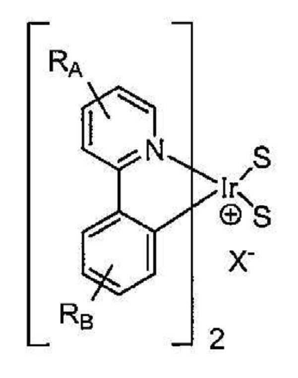
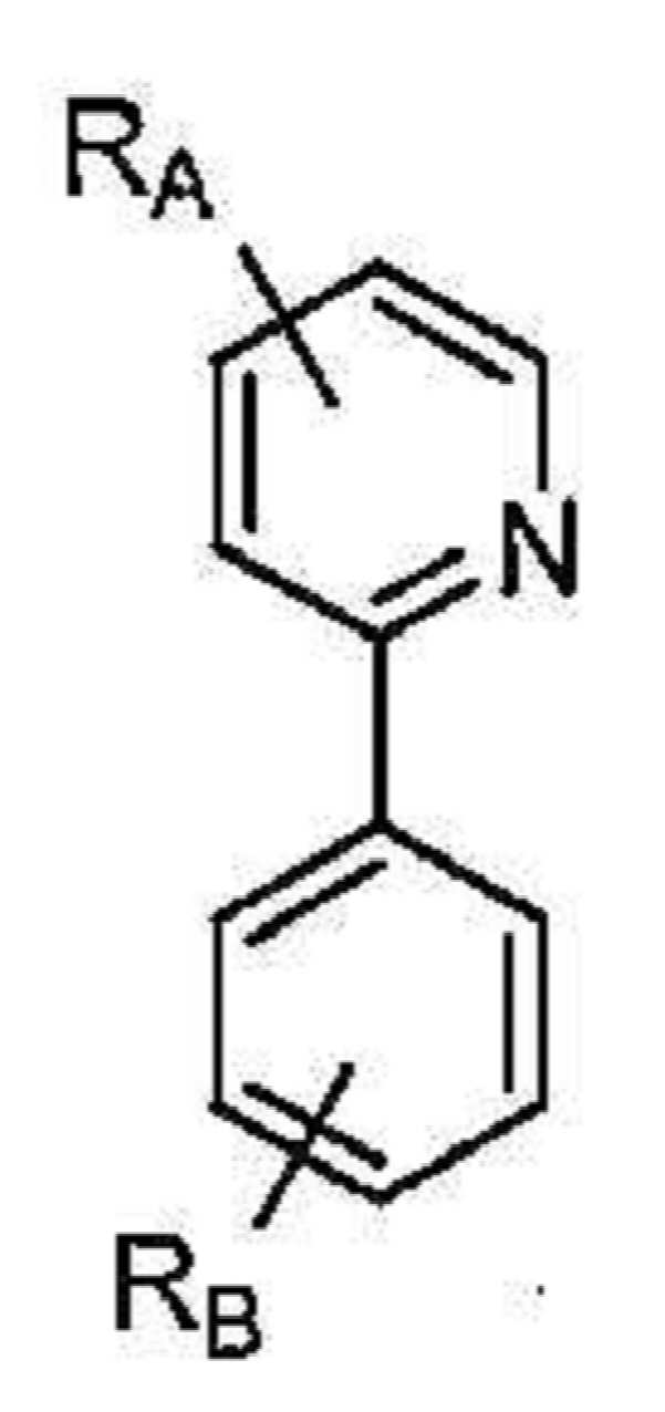

화합물 21, 22 및 24를 비롯한 특정 화합물은 이러한 방법을 이용하여 형성할 수 있다.Certain compounds can be formed using this method, including
동종리간드성 Ir(Ⅲ) 화합물의 제2 제조 방법이 제공된다. 상기 제2 방법은A second method for producing a homoligand Ir (III) compound is provided. The second method
용매의 존재 하에 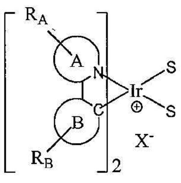


RA 및 RB 중 1 이상은 알킬기이고, 상기 알킬기는 피리딘 고리 상의 질소에 인접한다. S는 중성 리간드이다. X는 카운터 이온이다. 바람직하게는, X는 트리플레이트이다. A 및 B는 각각 독립적으로 5원 또는 6원 탄소환 또는 이종환 고리이다. A-B는 고리 A 상의 질소 원자 및 고리 B 상의 sp2 혼성화 탄소 원자를 통해 이리듐에 배위 결합된 탄소환 또는 이종환 고리의 결합쌍을 나타낸다. RA 및 RB 각각은 모노, 디, 트리 또는 테트라 치환을 나타낼 수 있다. RA 및 RB는 각각 독립적으로 수소, 알킬, 알콕시, 아미노, 알케닐, 알키닐, 아릴킬, 아릴 및 헤테로아릴로 구성된 군으로부터 선택된다.At least one of R A and R B is an alkyl group, which is adjacent to the nitrogen on the pyridine ring. S is a neutral ligand. X is a counter ion. Preferably, X is triflate. A and B are each independently a 5- or 6-membered carbocyclic ring or a heterocyclic ring. AB represents a bonding pair of carbocyclic or heterocyclic rings coordinated to iridium via a nitrogen atom on ring A and an sp 2 hybridized carbon atom on ring B. Each of R A and R B may represent mono, di, tri or tetra substitutions. R A and R B are each independently selected from the group consisting of hydrogen, alkyl, alkoxy, amino, alkenyl, alkynyl, arylalkyl, aryl and heteroaryl.
바람직하게는, A는 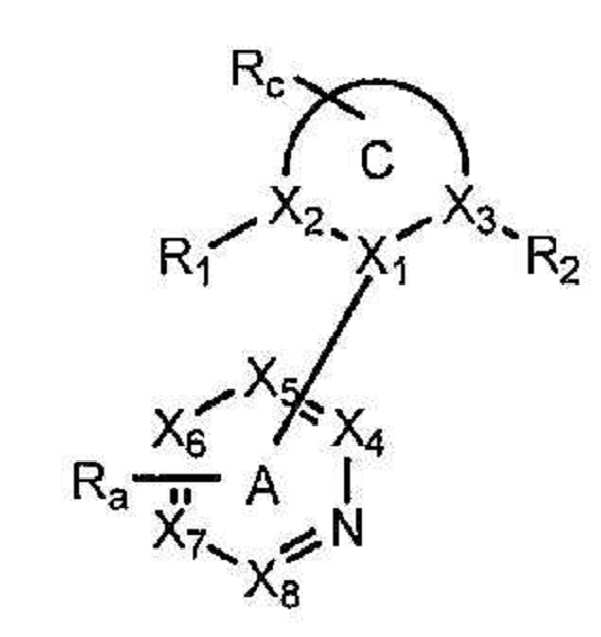
C는 5원 또는 6원 탄소환 또는 이종환 고리이다. A-C는 탄소환 또는 이종환 고리의 결합쌍을 나타낸다. RA 및 Rc는 모노, 디, 트리 또는 테트라 치환을 나타낼 수 있다. RA 및 Rc는 독립적으로 수소, 알킬, 알콕시, 아미노, 알케닐, 알키닐, 아릴킬, 아릴 및 헤테로아릴로 구성된 군으로부터 선택된다. X1, X2, X3, X4, X5, X6, X7, X8 및 X9은 독립적으로 탄소 및 질소로부터 선택된다. R1 및 R2는 독립적으로 수소, 알킬, 알콕시, 아미노, 알케닐, 알키닐, 아릴킬, 아릴 및 헤테로아릴로 구성된 군으로부터 선택된다. C에 인접한 R1, R2 및 Ra 치환기들 중 1 이상은 수소가 아니다.C is a 5- or 6-membered carbocyclic or heterocyclic ring. AC represents a bonding pair of carbocyclic or heterocyclic rings. R A and Rc may represent mono, di, tri or tetra substitutions. R A and R c are independently selected from the group consisting of hydrogen, alkyl, alkoxy, amino, alkenyl, alkynyl, arylalkyl, aryl and heteroaryl. X 1 , X 2 , X 3 , X 4 , X 5 , X 6 , X 7 , X 8 and X 9 are independently selected from carbon and nitrogen. R 1 and R 2 are independently selected from the group consisting of hydrogen, alkyl, alkoxy, amino, alkenyl, alkynyl, arylalkyl, aryl and heteroaryl. At least one of the R 1 , R 2 and R a substituents adjacent to C is not hydrogen.
한 양태에서, 상기 제2 방법은In one aspect, the second method is
용매의 부재 하에 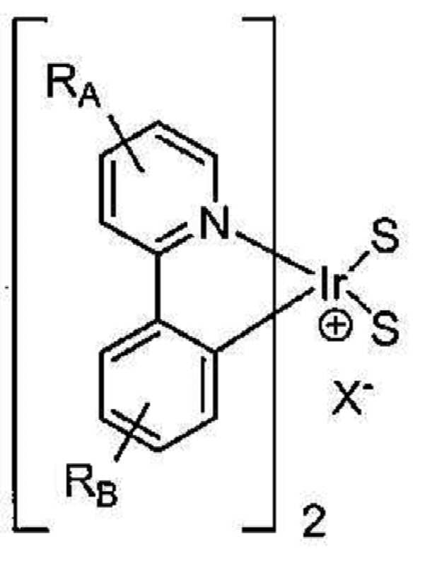


화합물 23을 비롯한 특정 화합물을 이러한 방법을 이용하여 형성할 수 있다.Certain compounds can be formed using this method, including compound 23.
구체적으로는, 화합물 23을Specifically, compound 23
용매의 부재 하에 130℃에서 16 시간 동안 
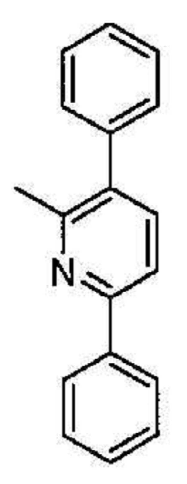
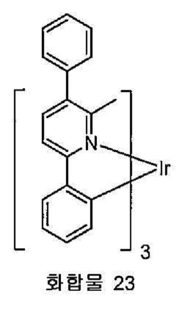
유기 발광 소자 중 특정 층에 유용한 것으로 본 원에서 기술된 물질을 상기 소자에 존재하는 광범위한 기타 물질과 병용할 수 있다. 예를 들어, 본 원에서 개시되는 발광 도판트를 호스트, 수송층, 차단층, 주입층, 전극 및 존재할 수 있는 기타 층과 함께 사용할 수 있다. 하기 기술되거나 참조되는 물질은 본 원에서 개시된 화합물과 조합하여 유용할 수 있는 물질의 비한정적인 예이며, 당업자는 문헌을 용이하게 참조하여 조합에 유용할 수 있는 기타 물질을 확인할 수 있다.Materials described herein as useful for certain layers of organic light emitting devices can be used in combination with a wide variety of other materials present in such devices. For example, the light emitting dopants disclosed herein can be used with a host, transport layer, barrier layer, injection layer, electrode, and other layers that may be present. The materials described or referenced below are non-limiting examples of materials that may be useful in combination with the compounds disclosed herein, and those skilled in the art can readily refer to the literature to identify other materials that may be useful in combination.
본 원에서 개시된 물질 이외에 및/또는 그와 함께, 많은 정공 주입 물질, 정공 수송 물질, 호스트 물질, 도판트 물질, 엑시톤/정공 차단층 물질, 전자 수송 및 전자 주입 물질을 OLED에 사용할 수 있다. 본 원에서 개시된 물질와 함께 OLED에 사용될 수 있는 물질의 비한정적인 예가 하기 표1에 기재되어 있다. 표 1은 물질의 비한정 부류, 각각의 부류에 대한 화합물의 비한정 예 및 상기 물질을 개시하는 참조 문헌을 기재한다.In addition to and / or with the materials disclosed herein, many hole injection materials, hole transport materials, host materials, dopant materials, exciton / hole blocking layer materials, electron transport and electron injection materials can be used in the OLED. Non-limiting examples of materials that can be used in OLEDs with the materials disclosed herein are listed in Table 1 below. Table 1 sets forth non-limiting classes of materials, non-limiting examples of compounds for each class, and references that disclose such materials.


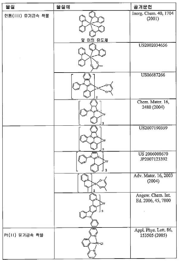
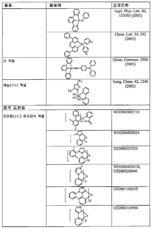


실시예Example
화합물예Compound example
일부 이종리간드성 Ir(Ⅲ) 착물을 하기와 같이 합성하였다.Some heteroligand Ir (III) complexes were synthesized as follows.
실시예 1. 화합물 1의 합성.Example 1. Synthesis of Compound 1

2-페닐-4-브로모피리딘의 합성. 디메톡시에탄 100 mL 및 물 40 mL 중 2,4-디브로모피리딘(10 g, 42.21 mmol), 페닐보론산(5.1 g, 42.21 mmol) 및 탄산칼륨(11.7 g, 84.42 mmol)의 혼합물을 제조하였다. 상기 혼합물에 질소를 30분 동안 직접 버블링하였다. 이어서, 테트라키스(트리페닐포스핀)팔라듐(0)(244 mg, 2.11 mmol)를 첨가하고, 상기 혼합물을 질소 하에 환류로 밤새 가열하였다. 상기 혼합물을 냉각시키고 아세트산에틸 및 물로 희석하였다. 상기 층을 분리시고, 수성상을 아세트산에틸로 추출하였다. 상기 유기층을 염수로 세척하고, 황산마그네슘 상에서 건조시키며, 여과시키고, 증발시켜 잔류물을 산출하였다. 상기 잔류물을 0%, 2%, 및 5% 아세트산에틸/헥산으로 용리시키는 칼럼 크로마토그래피에 의해 정제하였다. 황색 액체 4.28 g(43%)을 수득하였다. Synthesis of 2-phenyl-4-bromopyridine. A mixture of 2,4-dibromopyridine (10 g, 42.21 mmol), phenylboronic acid (5.1 g, 42.21 mmol) and potassium carbonate (11.7 g, 84.42 mmol) in 100 mL of dimethoxyethane and 40 mL of water was prepared. It was. Nitrogen was bubbled directly into the mixture for 30 minutes. Tetrakis (triphenylphosphine) palladium (0) (244 mg, 2.11 mmol) was then added and the mixture was heated to reflux overnight under nitrogen. The mixture was cooled and diluted with ethyl acetate and water. The layer was separated and the aqueous phase was extracted with ethyl acetate. The organic layer was washed with brine, dried over magnesium sulfate, filtered and evaporated to yield a residue. The residue was purified by column chromatography eluting with 0%, 2%, and 5% ethyl acetate / hexanes. 4.28 g (43%) of a yellow liquid were obtained.

2-페닐-4(4,4,5,5-테트라메틸-l,3,2-디옥사보롤란-2일)피리딘의 합성. 디옥산 100 mL 중 2-페닐-4-브로모피리딘(4.28 g, 18.28 mmol), 비스(피나콜라토)디보론(9.29 g, 36.57 mmol) 및 아세트산칼륨(5.38 g, 54.84 mmol)의 혼합물을 제조하였다. 상기 혼합물에 질소를 30분 동안 직접 버블링하였다. 디클로로[1,1'-페로세닐비스(디페닐포스핀)]팔라듐(Ⅱ) 디클로로메탄(448 mg, 0.55 mmol)을 첨가하고, 추가 15 분 동안 질소 버블링하였다. 상기 반응 혼합물을 내부 90℃로 가열하였다. 1 시간 후, 반응이 완료되었으며, 가열을 중지하였다. 용매를 증발시켜 오일을 산출하였다. 상기 오일을 200℃에서 Kugelrohr에 의해 정제하여 과량의 비스(피나콜라토)디보론을 제거하였다. 보일링팟에 남아 있는 잔류물을 아세트산에틸에 용해시키고, 황산마그네슘을 통해 여과시키며, 아세트산에틸로 세정하고, 여과물을 증발시켰다. 다음 단계에서 기술되는 바와 같이 사용하였다. 산출량은 생성물 대략 4 g이었다. Synthesis of 2-phenyl-4 (4,4,5,5-tetramethyl-l, 3,2-dioxaborolan-2yl) pyridine. A mixture of 2-phenyl-4-bromopyridine (4.28 g, 18.28 mmol), bis (pinacolato) diboron (9.29 g, 36.57 mmol) and potassium acetate (5.38 g, 54.84 mmol) in 100 mL dioxane Prepared. Nitrogen was bubbled directly into the mixture for 30 minutes. Dichloro [1,1'-ferrocenylbis (diphenylphosphine)] palladium (II) dichloromethane (448 mg, 0.55 mmol) was added and nitrogen bubbled for an additional 15 minutes. The reaction mixture was heated to internal 90 ° C. After 1 hour the reaction was complete and the heating was stopped. The solvent was evaporated to yield an oil. The oil was purified by Kugelrohr at 200 ° C. to remove excess bis (pinacolato) diboron. The residue remaining in the boiling pot was dissolved in ethyl acetate, filtered through magnesium sulfate, washed with ethyl acetate and the filtrate was evaporated. Used as described in the next step. The yield was approximately 4 g of product.

PPY 이량체의 합성. 염화이리듐 14.7 g(0.04 mol) 및 2-페닐피리딘 26.0 g(0.17 mol)을 1L의 둥근 바닥 플라스크에 투입하였다. 2-에톡시에탄올 300 ml 및 물 100 ml를 첨가하였다. 상기 혼합물을 질소 분위기 하에서 밤새 환류시켰다. 실온으로 냉각시킨 후, 침전물을 여과시키고, 메탄올로 세척하였다. 건조 후, 이량체 22 g을 수득하였다. (99% 수율). Synthesis of PPY Dimer. 14.7 g (0.04 mol) of iridium chloride and 26.0 g (0.17 mol) of 2-phenylpyridine were charged to a 1 L round bottom flask. 300 ml of 2-ethoxyethanol and 100 ml of water were added. The mixture was refluxed overnight under a nitrogen atmosphere. After cooling to room temperature, the precipitate was filtered off and washed with methanol. After drying, 22 g of dimer was obtained. (99% yield).

트리플레이트의 합성. 이량체 22 g을 디클로로메탄 1 L에 용해시켰다. 은 트리플레이트 10.5 g(0.04 mol)을 상기 용액에 첨가하였다. 이어서, 메탄올 25 ml을 첨가하였다. 상기 용액을 5 시간 동안 교반하였다. 상기 염화은을 여과시켰다. 상기 용매를 증발시켰다. 생성물 26 g을 수득하였다. 상기 고체를 추가 정제 없이 다음 단계에서 사용하였다. Synthesis of Triflate. 22 g of dimer was dissolved in 1 L of dichloromethane. 10.5 g (0.04 mol) of silver triflate was added to the solution. Then 25 ml of methanol were added. The solution was stirred for 5 hours. The silver chloride was filtered off. The solvent was evaporated. 26 g of product was obtained. The solid was used in the next step without further purification.

보론산 에스테르 전구체의 합성. 에탄올 100 mL 중 상기 트리플레이트(4.6 g, 7.11 mmol) 및 2-페닐-4(4,4,5,5-테트라메틸-l,3,2-디옥사보롤란-2일)피리딘(∼4 g, ∼14.23 mmol)의 혼합물을 제조하였다. 상기 혼합물을 질소 하에 환류로 6 시간 동안 가열하였다. 상기 용매를 증발시키고, 헥산을 첨가하였다. 상기 고체를 여과시키고, 이를 헥산으로 세척하였다. 상기 고체를 디클로로메탄으로 용리시키는 칼럼 크로마토그래피로 정제한 후, 일부 메탄올을 첨가하였다. 오랜지색 고체 0.92 g(대략 17%)을 수득하였다. Synthesis of Boronic Acid Precursor. The triflate (4.6 g, 7.11 mmol) and 2-phenyl-4 (4,4,5,5-tetramethyl-l, 3,2-dioxaborolan-2yl) pyridine (~ 4 in 100 mL of ethanol) g, ˜14.23 mmol) was prepared. The mixture was heated to reflux under nitrogen for 6 hours. The solvent was evaporated and hexanes added. The solid was filtered off and washed with hexane. The solid was purified by column chromatography eluting with dichloromethane and then some methanol was added. 0.92 g (approximately 17%) of an orange solid were obtained.

화합물 1의 합성. 톨루엔 50 mL 및 물 5 mL 중 상기 보론산 에스테르 전구체(0.92 g, 1.18 mmol), 브로모벤젠(0.6 g, 3.54 mmol), 2-디시클로펙실포스피노-2',6'-디메톡시비페닐(19 mg, 0.047 mmol) 및 제3인산칼륨(0.82 g, 3.54 mmol)을 혼합하였다. 상기 혼합물에 직접 질소를 30 분 동안 버블링한 후, 트리스(디벤질리덴아세톤)디팔라듐(0)(11 mg, 0.0118 mmol)을 첨가하였다. 추가 5 분 동안 질소로 버블링하고, 이어서 상기 반응 혼합물을 질소 하에 1 시간 동안 환류로 가열하였다. 상기 혼합물을 냉각시키고, 오랜지색 고체가 침전하였다. 상기 고체를 여과시키고, 헥산에 의해 세척한 후, 메탄올로 세척하였다. 여과물에 일부 고체가 확인되어, 여과물을 증발시키고, 메탄올을 첨가하였다. 더 많은 오랜지색 고체가 여과되었다. 모든 고체를 50% 디클로로메탄/헥산으로 용리시키는 칼럼 크로마토그래피에 의해 정제하였다. 상기 고체는 280℃에서 승화하였다. 0.53 g(62%)을 수득하였다. Synthesis of Compound 1. The boronic acid ester precursor (0.92 g, 1.18 mmol), bromobenzene (0.6 g, 3.54 mmol), 2-dicyclopexylphosphino-2 ', 6'-dimethoxybiphenyl in 50 mL toluene and 5 mL water (19 mg, 0.047 mmol) and potassium triphosphate (0.82 g, 3.54 mmol) were mixed. Nitrogen was bubbled directly into the mixture for 30 minutes, then tris (dibenzylideneacetone) dipalladium (0) (11 mg, 0.0118 mmol) was added. Bubbling with nitrogen for an additional 5 minutes, then the reaction mixture was heated to reflux under nitrogen for 1 hour. The mixture was cooled and an orange solid precipitated out. The solid was filtered off, washed with hexane and then with methanol. Some solids were found in the filtrate, the filtrate was evaporated and methanol was added. More orange solids were filtered out. All solids were purified by column chromatography eluting with 50% dichloromethane / hexanes. The solid sublimed at 280 ° C. 0.53 g (62%) was obtained.
실시예 2. 화합물 2의 합성.Example 2. Synthesis of
하기 합성을 이용하여 화합물 2를 제조하였다.
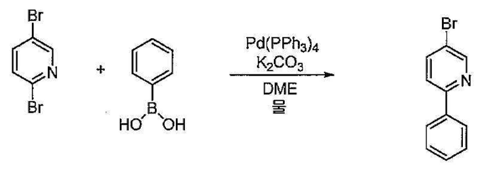
2-페닐-5-브로모피리딘의 합성. 디메톡시에탄 100 mL 및 물 40 mL 중 2,5-디브로모피리딘(10 g, 42.21 mmol), 페닐보론산(5.1 g, 42.21 mmol) 및 탄산칼륨(11.7 g, 84.42 mmol)의 혼합물을 제조하였다. 상기 혼합물에 질소를 30분 동안 직접 버블링하였다. 이어서, 테트라키스(트리페닐포스핀)팔라듐(0)(244 mg, 2.11 mmol)를 첨가하고, 상기 혼합물을 질소 하에 환류로 밤새 가열하였다. 상기 혼합물을 냉각시키고 아세트산에틸 및 물로 희석하였다. 상기 층을 분리시고, 수성상을 아세트산에틸로 추출하였다. 상기 유기층을 염수로 세척하고, 황산마그네슘 상에서 건조시키며, 여과시키고, 증발시켜 잔류물을 산출하였다. 상기 잔류물을 0%, 2%, 및 5% 아세트산에틸/헥산으로 용리시키는 칼럼 크로마토그래피에 의해 정제하였다. Synthesis of 2-phenyl-5-bromopyridine. A mixture of 2,5-dibromopyridine (10 g, 42.21 mmol), phenylboronic acid (5.1 g, 42.21 mmol) and potassium carbonate (11.7 g, 84.42 mmol) in 100 mL of dimethoxyethane and 40 mL of water was prepared. It was. Nitrogen was bubbled directly into the mixture for 30 minutes. Tetrakis (triphenylphosphine) palladium (0) (244 mg, 2.11 mmol) was then added and the mixture was heated to reflux overnight under nitrogen. The mixture was cooled and diluted with ethyl acetate and water. The layer was separated and the aqueous phase was extracted with ethyl acetate. The organic layer was washed with brine, dried over magnesium sulfate, filtered and evaporated to yield a residue. The residue was purified by column chromatography eluting with 0%, 2%, and 5% ethyl acetate / hexanes.

2-페닐-5-(4,4,5,5-테트라메틸-l,3,2-디옥사보롤란-2-일)피리딘의 합성. 디옥산 100 mL 중 2-페닐-4-브로모피리딘(4.28 g, 18.28 mmol), 비스(피나콜라토)디보론(9.29 g, 36.57 mmol) 및 아세트산칼륨(5.38 g, 54.84 mmol)의 혼합물을 제조하였다. 상기 혼합물에 질소를 30분 동안 직접 버블링하였다. 디클로로[1,1'-페로세닐비스(디페닐포스핀)]팔라듐(Ⅱ) 디클로로메탄(448 mg, 0.55 mmol)을 첨가하였다. 상기 반응 혼합물을 내부 90℃로 3 시간 동안 가열하였다. 용매를 증발시켜 오일을 산출하였다. 상기 오일을 Kugelrohr에 의해 정제하여 과량의 비스(피나콜라토)디보론을 제거하였다. 보일링팟에 남아 있는 잔류물을 아세트산에틸에 용해시키고, 황산마그네슘을 통해 여과시키며, 아세트산에틸로 세정하고, 여과물을 증발시켰다. 상기 생성물을 다음 단계에서 추가 정제 없이 사용할 수 있었다. Synthesis of 2-phenyl-5- (4,4,5,5-tetramethyl-l, 3,2-dioxaborolan-2-yl) pyridine. A mixture of 2-phenyl-4-bromopyridine (4.28 g, 18.28 mmol), bis (pinacolato) diboron (9.29 g, 36.57 mmol) and potassium acetate (5.38 g, 54.84 mmol) in 100 mL dioxane Prepared. Nitrogen was bubbled directly into the mixture for 30 minutes. Dichloro [1,1'-ferrocenylbis (diphenylphosphine)] palladium (II) dichloromethane (448 mg, 0.55 mmol) was added. The reaction mixture was heated to internal 90 ° C. for 3 hours. The solvent was evaporated to yield an oil. The oil was purified by Kugelrohr to remove excess bis (pinacolato) diboron. The residue remaining in the boiling pot was dissolved in ethyl acetate, filtered through magnesium sulfate, washed with ethyl acetate and the filtrate was evaporated. The product could be used without further purification in the next step.

보론산 에스테르 전구체의 합성. 에탄올 100 mL 중 상기 트리플레이트(4.6 g, 7.11 mmol) 및 2-페닐-5-(4,4,5,5-테트라메틸-l,3,2-디옥사보롤란-2일)피리딘(∼4 g, ∼14.23 mmol)의 혼합물을 제조하였다. 상기 혼합물을 질소 하에 환류로 24 시간 동안 가열하였다. 상기 용매를 증발시키고, 헥산을 첨가하였다. 상기 고체를 여과시키고, 이를 헥산으로 세척하였다. 상기 고체를 디클로로메탄으로 용리시키는 칼럼 크로마토그래피로 정제한 후, 일부 메탄올을 첨가하였다. Synthesis of Boronic Acid Precursor. The triflate (4.6 g, 7.11 mmol) and 2-phenyl-5- (4,4,5,5-tetramethyl-l, 3,2-dioxaborolan-2yl) pyridine in 100 mL of ethanol 4 g,-14.23 mmol) was prepared. The mixture was heated to reflux under nitrogen for 24 h. The solvent was evaporated and hexanes added. The solid was filtered off and washed with hexane. The solid was purified by column chromatography eluting with dichloromethane and then some methanol was added.
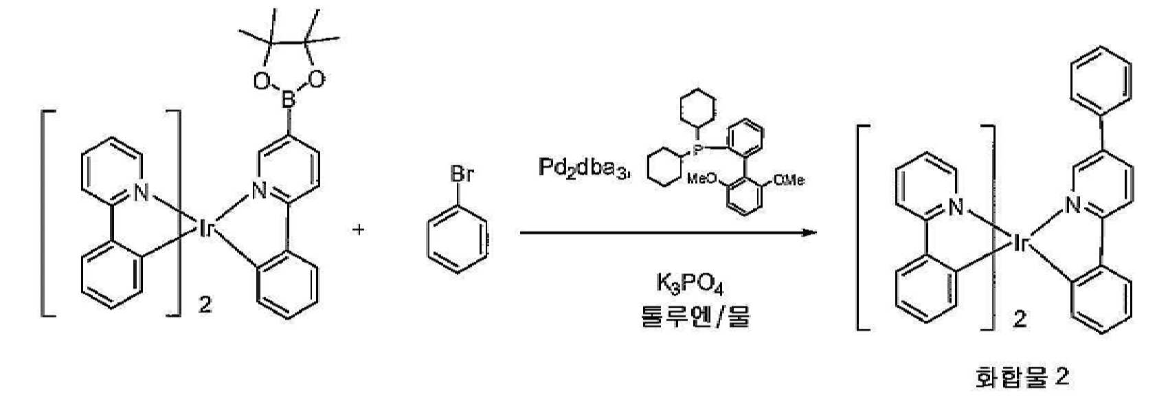
화합물 2의 합성. 톨루엔 50 mL 및 물 5 mL 중 상기 보론산 에스테르 전구체(0.92 g, 1.18 mmol), 브로모벤젠(0.6 g, 3.54 mmol), 2-디시클로펙실포스피노-2',6'-디메톡시비페닐(19 mg, 0.047 mmol) 및 제3인산칼륨(0.82 g, 3.54 mmol)을 혼합하였다. 상기 혼합물에 직접 질소를 30 분 동안 버블링한 후, 트리스(디벤질리덴아세톤)디팔라듐(0)(11 mg, 0.0118 mmol)을 첨가하였다. 추가 5 분 동안 질소로 버블링하고, 이어서 상기 반응 혼합물을 질소 하에 1 시간 동안 환류로 가열하였다. 상기 혼합물을 냉각시키고, 오랜지색 고체를 형성하였다. 상기 고체를 여과시키고, 헥산에 의해 세척한 후, 메탄올로 세척하였다. 상기 고체를 50% 디클로로메탄/헥산으로 용리시키는 칼럼 크로마토그래피에 의해 정제하였다. Synthesis of
실시예 3. 화합물 3의 합성.Example 3. Synthesis of Compound 3

Irppy 중간생성물(0.70 g, 0.90 mmol), 2-브로모피리미딘( 0.71 g, 4.5 mmol), 트리스(디벤질리덴아세톤)디팔라듐(0)[Pd2(dba)3](0.01 g, 1 mol%), 트리시클로펙실포스핀(0.05 g, 0.18 mmol) 및 제3인산칼륨(K3PO4)(0.7 g, 3.3 mmol)을 10O mL의 3목 둥근 바닥 플라스크에 계량투입하였다. 톨루엔 40 mL 및 물 10 mL을 상기 반응 용기에 첨가하였다. 상기 혼합물에 질소를 직접 1 시간 동안 버블링시켜 상기 반응 혼합물을 탈기시켰다. 상기 용액을 2 시간 동안 환류로 가열하였다. 냉각 후, 상기 생성물을 여과시키고, 염화메틸렌에 용해시키며, 이동상으로서 염화메틸렌:헥산(50:50)에 의해 실리카 겔을 이용하여 크로마토그래피 처리하였다. 회전 증발기를 이용하여 용매를 제거하고, 생성물을 진공 하에 건조시켜 생성물 0.6 g(90% 수율)을 산출하였다.Irppy intermediate (0.70 g, 0.90 mmol), 2-bromopyrimidine (0.71 g, 4.5 mmol), tris (dibenzylideneacetone) dipalladium (0) [Pd 2 (dba) 3 ] (0.01 g, 1 mol%), tricyclopexylphosphine (0.05 g, 0.18 mmol) and potassium triphosphate (K3PO4) (0.7 g, 3.3 mmol) were metered into a 100 mL three neck round bottom flask. 40 mL of toluene and 10 mL of water were added to the reaction vessel. The reaction mixture was degassed by bubbling nitrogen directly into the mixture for 1 hour. The solution was heated to reflux for 2 hours. After cooling, the product was filtered off, dissolved in methylene chloride and chromatographed using silica gel with methylene chloride: hexane (50:50) as mobile phase. The solvent was removed using a rotary evaporator and the product dried under vacuum to yield 0.6 g (90% yield) of product.
실시예 4. 화합물 4의 합성.Example 4. Synthesis of

Irppy 중간생성물(1.0 g, 1.3 mmol), 2-브로모피리딘(1.01 g, 6.4 mmol), 트리스(디벤질리덴아세톤)디팔라듐(0)[Pd2(dba)3](0.05 g, 1 mol%), 트리시클로펙실포스핀(0.08 g, 5 mol %) 및 제3인산칼륨(K3PO4) (4.0 g, 19.0 mmol)을 10O mL의 3목 둥근 바닥 플라스크에 계량투입하였다. 디옥산 50 mL 및 물 10 mL을 상기 반응 용기에 첨가하였다. 상기 혼합물에 질소를 직접 1 시간 동안 버블링시켜 상기 반응 혼합물을 탈기시켰다. 상기 용액을 2 시간 동안 환류로 가열하였다. 냉각 후, 상기 생성물을 여과시키고, 염화메틸렌에 용해시키며, 이동상으로서 염화메틸렌:헥산(50:50)에 의해 실리카 겔을 이용하여 크로마토그래피 처리하였다. 회전 증발기를 이용하여 용매를 제거하고, 생성물을 진공 하에 건조시켜 생성물 0.8 g(86% 수율)을 산출하였다.Irppy intermediate (1.0 g, 1.3 mmol), 2-bromopyridine (1.01 g, 6.4 mmol), tris (dibenzylideneacetone) dipalladium (0) [Pd 2 (dba) 3 ] (0.05 g, 1 mol %), Tricyclopexylphosphine (0.08 g, 5 mol%) and potassium triphosphate (K 3 PO 4 ) (4.0 g, 19.0 mmol) were metered into a 100 mL three neck round bottom flask. 50 mL of dioxane and 10 mL of water were added to the reaction vessel. The reaction mixture was degassed by bubbling nitrogen directly into the mixture for 1 hour. The solution was heated to reflux for 2 hours. After cooling, the product was filtered off, dissolved in methylene chloride and chromatographed using silica gel with methylene chloride: hexane (50:50) as mobile phase. The solvent was removed using a rotary evaporator and the product dried under vacuum to yield 0.8 g (86% yield) of product.
실시예 5. 화합물 5의 합성.Example 5. Synthesis of Compound 5
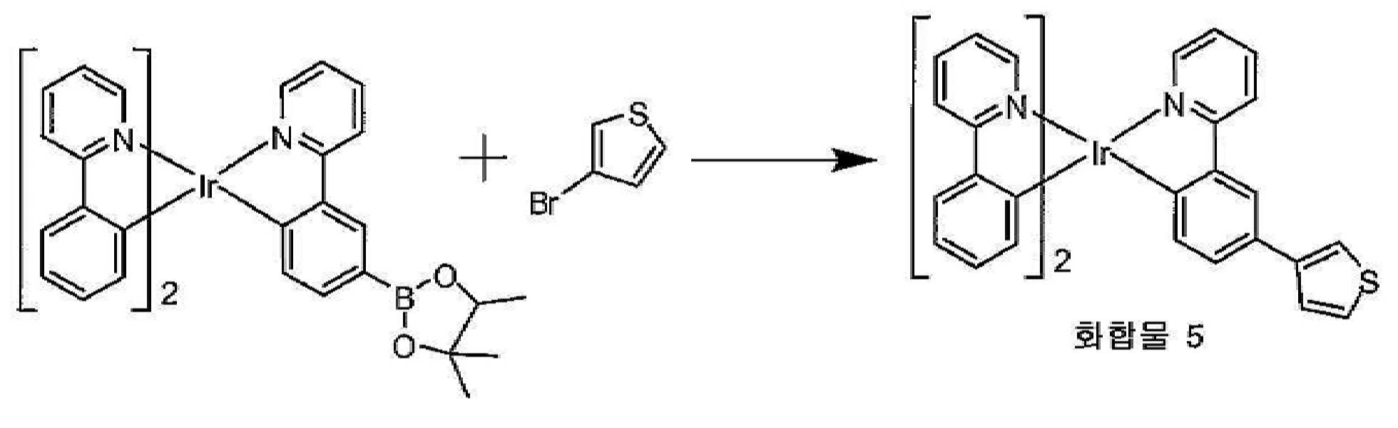
Irppy 중간생성물(1.50 g, 1.90 mmol), 3-브로모티오펜(1.61 g, 9.6 mmol), 트리스(디벤질리덴아세톤)디팔라듐(0)[Pd2(dba)3](0.02 g, 1 mol%), 트리시클로펙실포스핀(0.04 g, 4 mol%) 및 제3인산칼륨(K3PO4)(1.2 g, 5.6 mmol)을 25O mL의 3목 둥근 바닥 플라스크에 계량투입하였다. 톨루엔 100 mL 및 물 10 mL을 상기 반응 용기에 첨가하였다. 상기 혼합물에 질소를 직접 1 시간 동안 버블링시켜 상기 반응 혼합물을 탈기시켰다. 상기 용액을 2 시간 동안 환류로 가열하였다. 냉각 후, 상기 생성물을 여과시키고, 염화메틸렌에 용해시키며, 이동상으로서 염화메틸렌:헥산(50:50)에 의해 실리카 겔을 이용하여 크로마토그래피 처리하였다. 회전 증발기를 이용하여 용매를 제거하고, 생성물을 진공 하에 건조시켜 생성물 1.0 g(74% 수율)을 산출하였다.Irppy intermediate (1.50 g, 1.90 mmol), 3-bromothiophene (1.61 g, 9.6 mmol), tris (dibenzylideneacetone) dipalladium (0) [Pd 2 (dba) 3 ] (0.02 g, 1 mol %), Tricyclopexylphosphine (0.04 g, 4 mol%) and potassium triphosphate (K 3 PO 4 ) (1.2 g, 5.6 mmol) were metered into a 250 mL three neck round bottom flask. 100 mL of toluene and 10 mL of water were added to the reaction vessel. The reaction mixture was degassed by bubbling nitrogen directly into the mixture for 1 hour. The solution was heated to reflux for 2 hours. After cooling, the product was filtered off, dissolved in methylene chloride and chromatographed using silica gel with methylene chloride: hexane (50:50) as mobile phase. Solvent was removed using a rotary evaporator and the product was dried under vacuum to yield 1.0 g (74% yield) of product.
실시예 6. 화합물 6의 합성.Example 6. Synthesis of Compound 6

Irppy 중간생성물(1.50 g, 1.90 mmol), 3-브로모티아나프텐(2.0 g, 9.6 mmol), 트리스(디벤질리덴아세톤)디팔라듐(0)[Pd2(dba)3](0.08 g, 1 mol%), 트리시클로펙실포스핀(0.2 g, 0.5 mmol) 및 제3인산칼륨(K3PO4)(1.2 g, 5.6 mmol)을 25O mL의 3목 둥근 바닥 플라스크에 계량투입하였다. 톨루엔 100 mL 및 물 10 mL을 상기 반응 용기에 첨가하였다. 상기 혼합물에 질소를 직접 1 시간 동안 버블링시켜 상기 반응 혼합물을 탈기시켰다. 상기 용액을 2 시간 동안 환류로 가열하였다. 냉각 후, 상기 생성물을 여과시키고, 염화메틸렌에 용해시키며, 이동상으로서 염화메틸렌:헥산(50:50)에 의해 실리카 겔을 이용하여 크로마토그래피 처리하였다. 회전 증발기를 이용하여 용매를 제거하고, 생성물을 진공 하에 건조시켜 생성물 1.2 g(80% 수율)을 산출하였다.Irppy intermediate (1.50 g, 1.90 mmol), 3-bromothianaphthene (2.0 g, 9.6 mmol), tris (dibenzylideneacetone) dipalladium (0) [Pd 2 (dba) 3 ] (0.08 g, 1 mol%), tricyclopexylphosphine (0.2 g, 0.5 mmol) and potassium triphosphate (K 3 PO 4 ) (1.2 g, 5.6 mmol) were metered into a 25O mL three necked round bottom flask. 100 mL of toluene and 10 mL of water were added to the reaction vessel. The reaction mixture was degassed by bubbling nitrogen directly into the mixture for 1 hour. The solution was heated to reflux for 2 hours. After cooling, the product was filtered off, dissolved in methylene chloride and chromatographed using silica gel with methylene chloride: hexane (50:50) as mobile phase. The solvent was removed using a rotary evaporator and the product dried under vacuum to yield 1.2 g (80% yield) of product.
실시예 7. 화합물 7의 합성.Example 7. Synthesis of Compound 7
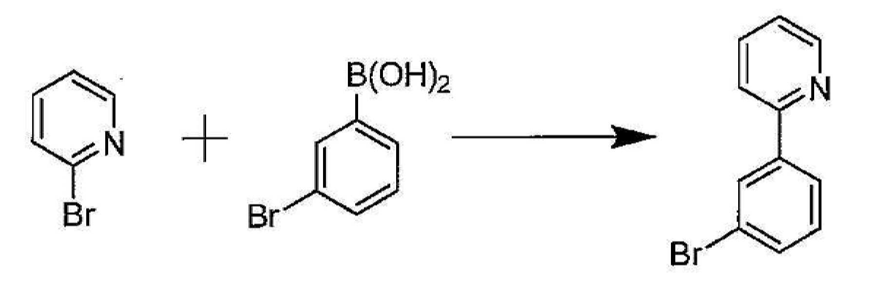
2-(3-브로모페닐)피리딘의 합성. 2-브로모피리딘(75.0 g, 475 mmol), 3-브로모페닐보론산(104.8 g, 520 mmol), 팔라듐 아세테이트(2.6 g, 2.5 mol%), 트리페닐포스핀(5.37 g, 5 mol%) 및 탄산칼륨(196.0 g, 1425 mmol)를 2 L의 3목 둥근 바닥 플라스틱에 투입하였다. 디메톡시 에탄 50O mL 및 H2O 50O mL를 상기 플라스크에 첨가하였다. 상기 용액을 통해 질소를 30 분 동안 버블링하고, 이어서 상기 용액을 질소 분위기 하에서 8 시간 동안 환류시켰다. 이어서, 반응을 실온으로 냉각시키고, 유기상을 상기 수성상으로부터 분리하였다. 상기 수성을 에틸아세테이트로 세척하고, 유기 분류를 배합하고, 황산마그네슘 상에서 건조시키며, 상기 용매를 진공 하에 제거하였다. 상기 생성물을 용리액으로서 에틸아세테이트 및 헥산에 의해 실리카 겔을 이용하여 크로마토그래피 처리하였다. 상기 용매를 제거하여 맑은 오일 84.O g(76% 수율)을 산출하였다. Synthesis of 2- (3-bromophenyl) pyridine. 2-bromopyridine (75.0 g, 475 mmol), 3-bromophenylboronic acid (104.8 g, 520 mmol), palladium acetate (2.6 g, 2.5 mol%), triphenylphosphine (5.37 g, 5 mol% ) And potassium carbonate (196.0 g, 1425 mmol) were charged to 2 L of a three-neck round bottom plastic. 50OmL of dimethoxy ethane and 50OmL of H 2 O were added to the flask. Nitrogen was bubbled through the solution for 30 minutes, and then the solution was refluxed for 8 hours under a nitrogen atmosphere. The reaction was then cooled to room temperature and the organic phase was separated from the aqueous phase. The aqueous was washed with ethyl acetate, the organic fractions were combined, dried over magnesium sulphate and the solvent was removed in vacuo. The product was chromatographed using silica gel with ethyl acetate and hexane as eluent. The solvent was removed to yield 84.O g (76% yield) of clear oil.

2-(3-(4,4,5,5-테트라메틸-l,3,2-디옥사보롤란-2-일)페닐)피리딘의 합성. 2-(3-브로모페닐)피리딘(25.0 g, 107 mmol), 비스(피나콜라토)디보론(54.2 g, 214 mmol), Pd(dppf)2Cl2(1.0 g, 10 mol%) 및 아세트산칼륨(31.5 g, 321 mmol)를 1 L의 둥근 바닥 플라스크에 투입하였다. 이어서, 디옥산 60O mL을 상기 플라스크에 첨가하였다. 상기 반응 혼합물에 통해 질소를 1 분 동안 버블링하고, 이어서 상기 플라스크를 질소 분위기 하에서 12 시간 동안 90℃로 가열하였다. 상기 디옥산을 회전 증발기로 감압 하에 제거하였다. 상기 암색 고체를 디클로로메탄 400 mL에 용해시키고, 2 in 두께의 실리카 겔 플러그에 통과시켰다. 상기 디클로로메탄을 회전 증발기로 감압 하에 제거하여 황색 오일을 남겼다. 이어서, 상기 생성물은 Kuglerohr 장치를 이용하여 증발시켜 백색 고체 23 g(77% 수율)을 산출하였다. Synthesis of 2- (3- (4,4,5,5-tetramethyl-l, 3,2-dioxaborolan-2-yl) phenyl) pyridine. 2- (3-bromophenyl) pyridine (25.0 g, 107 mmol), bis (pinacolato) diboron (54.2 g, 214 mmol), Pd (dppf) 2 Cl 2 (1.0 g, 10 mol%) and Potassium acetate (31.5 g, 321 mmol) was added to a 1 L round bottom flask. Next, 60 mL of dioxane was added to the flask. Nitrogen was bubbled through the reaction mixture for 1 minute, and the flask was then heated to 90 ° C. for 12 hours under a nitrogen atmosphere. The dioxane was removed under reduced pressure with a rotary evaporator. The dark solid was dissolved in 400 mL of dichloromethane and passed through a 2 in thick silica gel plug. The dichloromethane was removed under reduced pressure with a rotary evaporator, leaving a yellow oil. The product was then evaporated using a Kuglerohr apparatus to yield 23 g (77% yield) of a white solid.

Irppy 중간생성물의 합성. Irppy 트리플레이트(17.5 g, 25 mmol) 및 3 몰당량의 2-(3-(4,4,5,5-테트라메틸-l,3,2-디옥사보롤란-2-일)페닐)피리딘(21.50 g, 117 mmol)을 2 L의 3목 둥근 바닥 플라스크에 투입하였다. 알콜 60O mL를 상기 반응 혼합물에 첨가하였다. 상기 혼합물에 질소를 직접 1 시간 동안 버블링시켜 상기 반응 혼합물을 탈기시켰다. 이어서, 상기 반응 혼합물을 밤새 환류시켰다(상기 반응 혼합물의 내부 온도는 78도임). 약 18 시간 후, 상기 생성물은 상기 고온 반응 혼합물로부터 이미 침전하였다. 실온으로 냉각시킨 후, 이소프로판올 200 mL를 첨가하여 상기 반응 혼합물로부터 더욱 많은 생성물을 침전시켰다. 이어서, 상기 반응 혼합물을 여과시키고, 상기 생성물/잔류물을 이소프판올로 세척하며(과량의 리간드 제거를 위함), 이어서 공기 건조시켜 생성물 12 g(60% 수율)을 산출하였다. Synthesis of Irppy Intermediates. Irppy triflate (17.5 g, 25 mmol) and 3 molar equivalents of 2- (3- (4,4,5,5-tetramethyl-l, 3,2-dioxaborolan-2-yl) phenyl) pyridine (21.50 g, 117 mmol) was charged to a 2 L three necked round bottom flask. 60 mL of alcohol was added to the reaction mixture. The reaction mixture was degassed by bubbling nitrogen directly into the mixture for 1 hour. The reaction mixture was then refluxed overnight (internal temperature of the reaction mixture was 78 degrees). After about 18 hours, the product has already precipitated from the hot reaction mixture. After cooling to room temperature, more than 200 mL of isopropanol was added to precipitate more product from the reaction mixture. The reaction mixture was then filtered and the product / residue was washed with isofpanol (to remove excess ligand) and then air dried to yield 12 g (60% yield) of product.
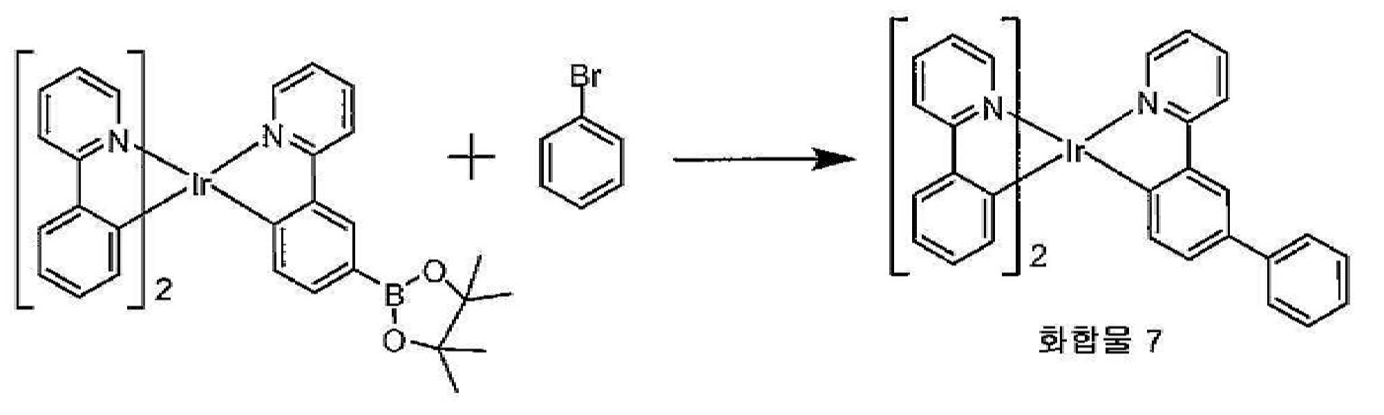
화합물 7의 합성. Irppy 중간생성물(0.50 g, 0.64 mmol), 브로모벤젠( 0.5 g, 3.2 mmol), 트리스(디벤질리덴아세톤)디팔라듐(O)[Pd2(dba)3](0.006 g, 0.0064 mmol), 2-디시클로펙실포스피노-2',6'-디메톡시비페닐(0.10 g, 0.025 mmol) 및 제3인산칼륨(K3PO4)(0.4 g, 1.92 mmol)을 10O mL의 3목 둥근 바닥 플라스크에 계량투입하였다. 톨루엔 40 mL 및 물 10 mL을 상기 반응 용기에 첨가하였다. 상기 혼합물에 질소를 직접 1 시간 동안 버블링시켜 상기 반응 혼합물을 탈기시켰다. 상기 용액을 2 시간 동안 환류로 가열하였다. 냉각 후, 상기 생성물을 여과시키고, 염화메틸렌에 용해시키며, 이동상으로서 염화메틸렌:헥산(50:50)에 의해 실리카 겔을 이용하여 크로마토그래피 처리하였다. 회전 증발기를 이용하여 용매를 제거하고, 생성물을 진공 하에 건조시켜 생성물 0.5 g(95% 수율)을 산출하였다. Synthesis of Compound 7. Irppy intermediate (0.50 g, 0.64 mmol), bromobenzene (0.5 g, 3.2 mmol), tris (dibenzylideneacetone) dipalladium (O) [Pd 2 (dba) 3 ] (0.006 g, 0.0064 mmol), 3-necked round of 2-dicyclopexylphosphino-2 ', 6'-dimethoxybiphenyl (0.10 g, 0.025 mmol) and potassium triphosphate (K 3 PO 4 ) (0.4 g, 1.92 mmol) Metered into the bottom flask. 40 mL of toluene and 10 mL of water were added to the reaction vessel. The reaction mixture was degassed by bubbling nitrogen directly into the mixture for 1 hour. The solution was heated to reflux for 2 hours. After cooling, the product was filtered off, dissolved in methylene chloride and chromatographed using silica gel with methylene chloride: hexane (50:50) as mobile phase. Solvent was removed using a rotary evaporator and the product was dried under vacuum to yield 0.5 g (95% yield) of product.
실시예 8. 화합물 2의 합성.Example 8. Synthesis of
하기 대안 합성을 이용하여 화합물 2를 제조하였다.

2,5-디페닐피리딘의 합성. 2,5-디브로모피리딘(10 g, 42 mmol), 페닐보론산(13.4 g, 110 mmol), 디시클로펙실(2',6'-디메톡시비페닐-2-일)포스핀(S-Phos)(0.7g, 1.6 mmol) 및 인산칼륨(22 g, 105 mmol)를 톨루엔 200 mL 및 물 20 mL에서 혼합하였다. 상기 혼합물에 질소를 30분 동안 직접 버블링하였다. 이어서, Pd2(dba)3(0.38 g, 0.4 mmol)를 첨가하고, 상기 혼합물을 질소 하에 2 시간 동안 환류로 가열하였다. 상기 혼합물을 냉각시키고, 유기층을 분리하였다. 상기 유기층을 염수로 세척하고, 황산마그네슘 상에서 건조시키며, 여과시키고, 증발시켜 잔류물을 산출하였다. 상기 잔류물을 10% 아세트산에틸/헥산으로 용리시키는 칼럼 크로마토그래피에 의해 정제하였다. 정제 후에 소정의 생성물 7 g을 수득하였다. (91.8% 수율). Synthesis of 2,5-diphenylpyridine. 2,5-dibromopyridine (10 g, 42 mmol), phenylboronic acid (13.4 g, 110 mmol), dicyclopexyl (2 ', 6'-dimethoxybiphenyl-2-yl) phosphine (S -Phos) (0.7 g, 1.6 mmol) and potassium phosphate (22 g, 105 mmol) were mixed in 200 mL of toluene and 20 mL of water. Nitrogen was bubbled directly into the mixture for 30 minutes. Then Pd 2 (dba) 3 (0.38 g, 0.4 mmol) was added and the mixture was heated to reflux for 2 hours under nitrogen. The mixture was cooled down and the organic layer was separated. The organic layer was washed with brine, dried over magnesium sulfate, filtered and evaporated to yield a residue. The residue was purified by column chromatography eluting with 10% ethyl acetate / hexanes. 7 g of the desired product was obtained after purification. (91.8% yield).

화합물 2의 합성. 상기 이리듐 트리플레이트 전구체(2.5 g, 3.5 mmol) 및 2,5-디페닐피리딘(2.4 g, 11 mmol)를 에탄올 200 mL에서 혼합하였다. 상기 혼합물을 질소 하에 환류로 24 시간 동안 가열하였다. 환류 중에 침전물이 형성되었다. 상기 반응 혼합물을 셀라이트 층을 통해 여과시켰다. 상기 생성물을 메탄올 및 헥산으로 세척하였다. 상기 고체를 디클로로메탄에 용해시키고, 디클로로메탄과 헥산을 1:1로 이용하는 칼럼에 의해 정제하였다. 칼럼 정제 후에 순수한 생성물 1.2 g을 수득하였다. (HPLC 순도: 99.8%) Synthesis of
실시예 9. 화합물 7의 대안 합성.Example 9. Alternative Synthesis of Compound 7
하기 대안 합성을 이용하여 화합물 2를 제조하였다.
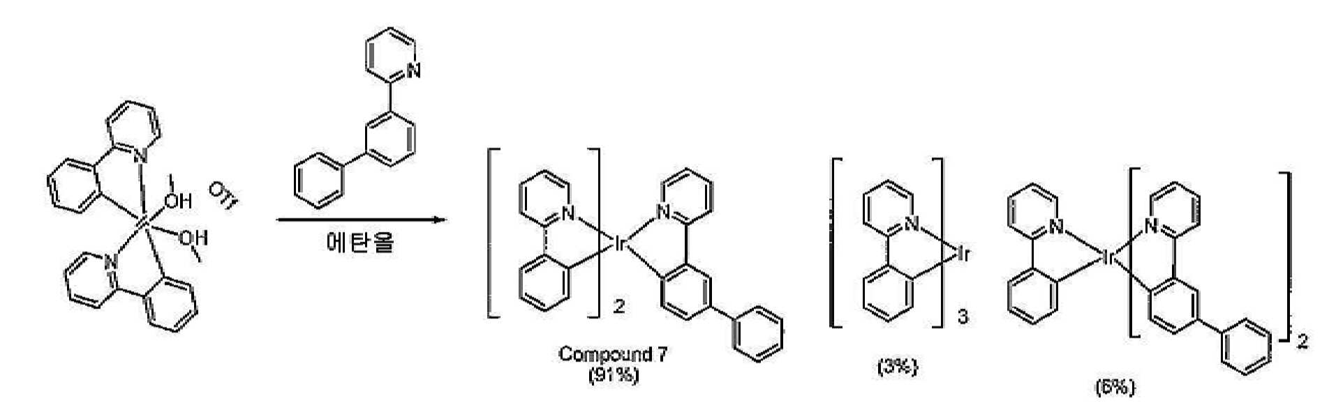
상기 이리듐 트리플레이트 전구체(2.5 g, 3.5 mmol) 및 2-(비페닐-3-일)피리딘 (2.4 g, 11 mmol)을 에탄올 200 mL에서 혼합하였다. 상기 혼합물을 질소 하에 환류로 24 시간 동안 가열하였다. 환류 중에 침전물이 형성되었다. 상기 반응 혼합물을 셀라이트 층을 통해 여과시켰다. 상기 생성물을 메탄올 및 헥산으로 세척하였다. 상기 고체를 디클로로메탄에 용해시키고, 디클로로메탄과 헥산을 1:1로 이용하는 칼럼에 의해 정제하였다. 칼럼 정제 후에 순수한 생성물 1.5 g을 수득하였다. (HPLC 순도: 99.6%)The iridium triflate precursor (2.5 g, 3.5 mmol) and 2- (biphenyl-3-yl) pyridine (2.4 g, 11 mmol) were mixed in 200 mL of ethanol. The mixture was heated to reflux under nitrogen for 24 h. A precipitate formed during reflux. The reaction mixture was filtered through a celite bed. The product was washed with methanol and hexanes. The solid was dissolved in dichloromethane and purified by column using dichloromethane and hexane 1: 1. 1.5 g of pure product was obtained after column purification. (HPLC purity: 99.6%)
실시예 10. 화합물 8의 합성.Example 10. Synthesis of Compound 8.

상기 이리듐 트리플레이트 전구체(2.5 g, 3.5 mmol) 및 2-(비페닐-4-일)피리딘(2.4 g, 11 mmol)을 에탄올 100 mL에서 혼합하였다. 상기 혼합물을 질소 하에 환류로 24 시간 동안 가열하였다. 환류 중에 침전물이 형성되었다. 상기 반응 혼합물을 셀라이트 층을 통해 여과시켰다. 상기 생성물을 메탄올 및 헥산으로 세척하였다. 상기 고체를 디클로로메탄에 용해시키고, 디클로로메탄과 헥산을 1:1로 이용하는 칼럼에 의해 정제하였다. 칼럼 정제 후에 순수한 생성물 1.2 g을 수득하였다. (HPLC 순도: 99.8%)The iridium triflate precursor (2.5 g, 3.5 mmol) and 2- (biphenyl-4-yl) pyridine (2.4 g, 11 mmol) were mixed in 100 mL of ethanol. The mixture was heated to reflux under nitrogen for 24 h. A precipitate formed during reflux. The reaction mixture was filtered through a celite bed. The product was washed with methanol and hexanes. The solid was dissolved in dichloromethane and purified by column using dichloromethane and hexane 1: 1. 1.2 g of pure product was obtained after column purification. (HPLC purity: 99.8%)
실시예 11. 화합물 9의 합성. Example 11. Synthesis of Compound 9

상기 이리듐 트리플레이트 전구체(2.5 g, 3.5 mmol) 및 2-(비페닐-4-일)-4-메틸피리딘(2.6 g, 11 mmol)을 에탄올 100 mL에서 혼합하였다. 상기 혼합물을 질소 하에 환류로 24 시간 동안 가열하였다. 환류 중에 침전물이 형성되었다. 상기 반응 혼합물을 셀라이트 층을 통해 여과시켰다. 상기 생성물을 메탄올 및 헥산으로 세척하였다. 상기 고체를 디클로로메탄에 용해시키고, 디클로로메탄과 헥산을 1:1로 이용하는 칼럼에 의해 정제하였다. 칼럼 정제 후에 순수한 생성물 1.3 g을 수득하였다. (HPLC 순도: 99.9%)The iridium triflate precursor (2.5 g, 3.5 mmol) and 2- (biphenyl-4-yl) -4-methylpyridine (2.6 g, 11 mmol) were mixed in 100 mL of ethanol. The mixture was heated to reflux under nitrogen for 24 h. A precipitate formed during reflux. The reaction mixture was filtered through a celite bed. The product was washed with methanol and hexanes. The solid was dissolved in dichloromethane and purified by column using dichloromethane and hexane 1: 1. 1.3 g of pure product was obtained after column purification. (HPLC purity: 99.9%)
실시예 12. 화합물 10의 합성.Example 12. Synthesis of Compound 10.

상기 이리듐 트리플레이트 전구체(2.0 g, 2.7 mmol) 및 2-(비페닐-4-일)-4-메틸피리딘(2.0 g, 8.2 mmol)을 에탄올 60 mL에서 혼합하였다. 상기 혼합물을 질소 하에 환류로 24 시간 동안 가열하였다. 환류 중에 침전물이 형성되었다. 상기 반응 혼합물을 셀라이트 층을 통해 여과시켰다. 상기 생성물을 메탄올 및 헥산으로 세척하였다. 상기 고체를 디클로로메탄에 용해시키고, 디클로로메탄과 헥산을 1:1로 이용하는 칼럼에 의해 정제하였다. 칼럼 정제 후에 순수한 생성물 1.6 g을 수득하였다. (HPLC 순도: 99.4%)The iridium triflate precursor (2.0 g, 2.7 mmol) and 2- (biphenyl-4-yl) -4-methylpyridine (2.0 g, 8.2 mmol) were mixed in 60 mL of ethanol. The mixture was heated to reflux under nitrogen for 24 h. A precipitate formed during reflux. The reaction mixture was filtered through a celite bed. The product was washed with methanol and hexanes. The solid was dissolved in dichloromethane and purified by column using dichloromethane and hexane 1: 1. 1.6 g of pure product was obtained after column purification. (HPLC purity: 99.4%)
실시예 13. 화합물 11의 합성.Example 13. Synthesis of Compound 11

상기 이리듐 트리플레이트 전구체 (1.2 g, 1.6 mmol) 및 2,5-디페닐피리딘 (1.2 g, 4.8 mmol)을 에탄올 50 mL에서 혼합하였다. 상기 혼합물을 질소 하에 환류로 24 시간 동안 가열하였다. 환류 중에 침전물이 형성되었다. 상기 반응 혼합물을 셀라이트 층을 통해 여과시켰다. 상기 생성물을 메탄올 및 헥산으로 세척하였다. 상기 고체를 디클로로메탄에 용해시키고, 디클로로메탄과 헥산을 1:1로 이용하는 칼럼에 의해 정제하였다. 칼럼 정제 후에 순수한 생성물 1.0 g을 수득하였다. (HPLC 순도: 99.3%)The iridium triflate precursor (1.2 g, 1.6 mmol) and 2,5-diphenylpyridine (1.2 g, 4.8 mmol) were mixed in 50 mL of ethanol. The mixture was heated to reflux under nitrogen for 24 h. A precipitate formed during reflux. The reaction mixture was filtered through a celite bed. The product was washed with methanol and hexanes. The solid was dissolved in dichloromethane and purified by column using dichloromethane and hexane 1: 1. 1.0 g of pure product was obtained after column purification. (HPLC purity: 99.3%)
유기 용매 중 상기 트리플레이트 중간생성물의 상기 제2 리간드와의 반응은 화합물 11에 대해서 도시된 바와 같이 흔히 그 반응 중에 스크램블링하는 리간드로 인해 혼합물을 생성한다. 흥미롭게는, 화합물 11의 합성 중에는 유의적인 스크램블링이 발생하지 않았다.The reaction of the triflate intermediate in the organic solvent with the second ligand often results in a mixture due to the ligand that scrambles during the reaction, as shown for compound 11. Interestingly, no significant scrambling occurred during the synthesis of compound 11.
그러나, 화합물 11 및 7 간의 구조적인 유사성(즉, 화합물 7은 상기 페닐 피리딘 리간드 상의 메틸기를 제외하고 화합물 7과 동일함)에도 불구하고 상기 방법을 이용한 화합물 7의 합성은 유의적인 스크램블링을 유도하였다. 특히, 상기 이리듐 트리플레이트 중간생성물은 환류 조건 하에 2,5-디페닐피리딘과 반응하였다. 상기 생성물은 하기 도시된 바와 같은 화합물 7 및 다른 2개의 스크램블링된 생성물의 혼합물이었다. 상기 화합물 극성의 유사성으로 인해, 정상 실리카 겔 크로마토그래피를 이용하여 화합물 7로부터 상기 불순물들을 분리하는 것은 매우 어렵다. However, despite the structural similarities between compounds 11 and 7 (ie, compound 7 is identical to compound 7 except for the methyl group on the phenyl pyridine ligand), the synthesis of compound 7 using the method induced significant scrambling. In particular, the iridium triflate intermediate was reacted with 2,5-diphenylpyridine under reflux conditions. The product was a mixture of compound 7 and the other two scrambled products as shown below. Due to the similarity of the compound polarity, it is very difficult to separate the impurities from compound 7 using normal silica gel chromatography.
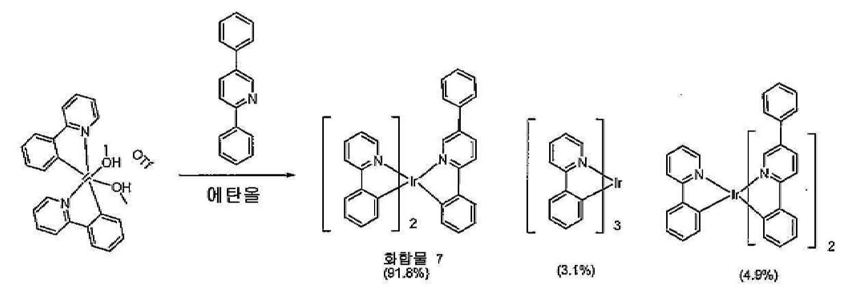
실시예 14. 화합물 12의 합성.Example 14. Synthesis of

상기 이리듐 트리플레이트 전구체(2.5 g, 3.5 mmol) 및 4-메틸-2,5-디페닐피리딘(2.6 g, 10.5 mmol)을 에탄올 100 mL에서 혼합하였다. 상기 혼합물을 질소 하에 환류로 24 시간 동안 가열하였다. 환류 중에 침전물이 형성되었다. 상기 반응 혼합물을 셀라이트 층을 통해 여과시켰다. 상기 생성물을 메탄올 및 헥산으로 세척하였다. 상기 고체를 디클로로메탄에 용해시키고, 디클로로메탄과 헥산을 1:1로 이용하는 칼럼에 의해 정제하였다. 칼럼 정제 후에 순수한 생성물 1.2 g을 수득하였다. (HPLC 순도: 99.9%)The iridium triflate precursor (2.5 g, 3.5 mmol) and 4-methyl-2,5-diphenylpyridine (2.6 g, 10.5 mmol) were mixed in 100 mL of ethanol. The mixture was heated to reflux under nitrogen for 24 h. A precipitate formed during reflux. The reaction mixture was filtered through a celite bed. The product was washed with methanol and hexanes. The solid was dissolved in dichloromethane and purified by column using dichloromethane and hexane 1: 1. 1.2 g of pure product was obtained after column purification. (HPLC purity: 99.9%)
실시예 15. 화합물 13의 합성. Example 15. Synthesis of

상기 이리듐 트리플레이트 전구체(2.5 g, 2.7 mmol) 및 2-(비페닐-4-일)-6-메틸피리딘(2.0 g, 8.1 mmol)을 20 mL의 반응 튜브에 투입하였다. 상기 반응 튜브를 배출시킨 후, 질소로 재충전하였다. 상기 공정을 3회 반복하였다. 상기 혼합물을 질소 하에 130℃에서 환류로 24 시간 동안 가열하였다. 상기 반응 혼합물을 디클로로메탄에 용해시키고, 디클로로메탄과 헥산을 1:1로 이용하는 칼럼에 의해 정제하였다. 칼럼 정제 후에 순수한 생성물 0.98 g을 수득하였다. (HPLC 순도: 99.8%)The iridium triflate precursor (2.5 g, 2.7 mmol) and 2- (biphenyl-4-yl) -6-methylpyridine (2.0 g, 8.1 mmol) were charged to a 20 mL reaction tube. After the reaction tube was drained, it was refilled with nitrogen. The process was repeated three times. The mixture was heated to reflux at 130 ° C. under nitrogen for 24 h. The reaction mixture was dissolved in dichloromethane and purified by column using dichloromethane and hexane 1: 1. 0.98 g of pure product was obtained after column purification. (HPLC purity: 99.8%)
실시예 16. 화합물 14의 합성.Example 16. Synthesis of Compound 14

상기 이리듐 트리플레이트 전구체(0.86 g, 1.15 mmol) 및 4-메틸-2,5-디페닐피리딘(0.85 g, 3.46 mmol)을 에탄올 30 mL에서 혼합하였다. 상기 혼합물을 질소 하에 환류로 24 시간 동안 가열하였다. 환류 중에 침전물이 형성되었다. 상기 반응 혼합물을 셀라이트 층을 통해 여과시켰다. 상기 생성물을 메탄올 및 헥산으로 세척하였다. 상기 고체를 디클로로메탄에 용해시키고, 디클로로메탄과 헥산을 1:1로 이용하는 칼럼에 의해 정제하였다. 칼럼 정제 후에 순수한 생성물 0.7 g을 수득하였다. (HPLC 순도: 99.5%) The iridium triflate precursor (0.86 g, 1.15 mmol) and 4-methyl-2,5-diphenylpyridine (0.85 g, 3.46 mmol) were mixed in 30 mL of ethanol. The mixture was heated to reflux under nitrogen for 24 h. A precipitate formed during reflux. The reaction mixture was filtered through a celite bed. The product was washed with methanol and hexanes. The solid was dissolved in dichloromethane and purified by column using dichloromethane and hexane 1: 1. 0.7 g of pure product was obtained after column purification. (HPLC purity: 99.5%)
상기 유기 용매 중 상기 트리플레이트 중간생성물의 상기 제2 리간드와의 반응은 화합물 11에 대해서 도시된 바와 같이 흔히 그 반응 중에 스크램블링하는 리간드로 인해 생성물들의 혼합물을 생성한다. 흥미롭게는, 화합물 10, 11 및 14의 합성 중에는 유의적인 스크램블링이 발생하지 않았다. 상기 침전물 중 소정 생성물의 함유율은 모든 경우에서 99% 초과였다. The reaction of the triflate intermediate in the organic solvent with the second ligand often results in a mixture of products due to the ligand that scrambles during the reaction, as shown for compound 11. Interestingly, no significant scrambling occurred during the synthesis of compounds 10, 11 and 14. The content of the desired product in the precipitate was above 99% in all cases.
특히, 화합물 11 및 7 간의 구조적인 유사성(즉, 화합물 7은 상기 페닐 피리딘 리간드 상의 메틸기를 제외하고 화합물 7과 동일함)에도 불구하고 상기 방법을 이용한 화합물 7의 합성은 유의적인 스크램블링을 유도하였다. 특히, 상기 이리듐 트리플레이트 중간생성물은 환류 조건 하에 2,5-디페닐피리딘과 반응하였다. 상기 생성물은 하기 도시된 바와 같은 화합물 7 및 다른 2개의 스크램블링된 생성물의 혼합물이었다. 상기 화합물 극성의 유사성으로 인해, 정상 실리카 겔 크로마토그래피를 이용하여 화합물 7로부터 상기 불순물들을 분리하는 것은 매우 어렵다.In particular, despite the structural similarities between compounds 11 and 7 (ie, compound 7 is identical to compound 7 except for the methyl group on the phenyl pyridine ligand), the synthesis of compound 7 using the method induced significant scrambling. In particular, the iridium triflate intermediate was reacted with 2,5-diphenylpyridine under reflux conditions. The product was a mixture of compound 7 and the other two scrambled products as shown below. Due to the similarity of the compound polarity, it is very difficult to separate the impurities from compound 7 using normal silica gel chromatography.
실시예 17. 화합물 21의 합성.Example 17. Synthesis of
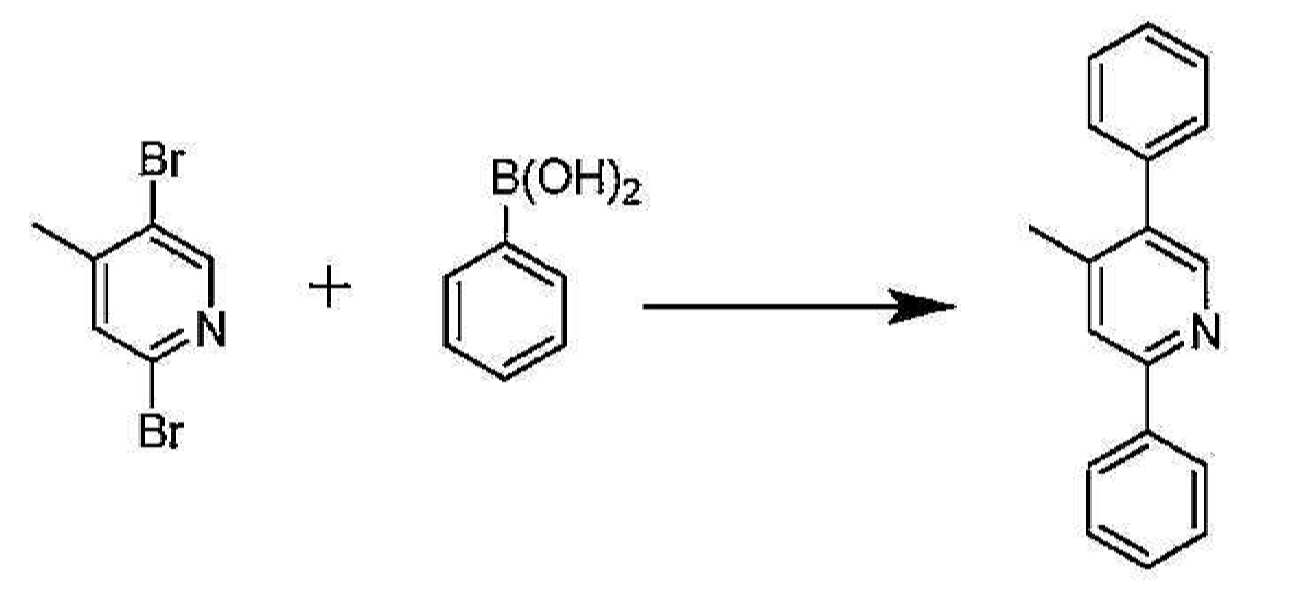
,5-디페닐-4-메틸피리딘의 합성. 페닐보론산(72.9 g, 598 mmol), 2,5-디브로모-4-메틸피리딘(50 g, 199 mmol), 2-디시클로펙실포스피노-2',6'-디메톡시비페닐(3.3 g, 8 mmol), 제3인산칼륨 일수화물(137 g, 595 mmol), 톨루엔 650 mL 및 물 150 mL를 2 L의 둥근 바닥 플라스크에 투입하였다. 상기 반응 혼합물에 직접 질소를 30 분 동안 버블링한 후, 트리스(디벤질리덴아세톤)디팔라듐(0)(1.79 g, 1.96 mmol)을 첨가하였다. 상기 반응 혼합물에 질소를 추가 15 분 동안 버블링한 후, 상기 반응 혼합물을 질소 하에 16 시간 동안 환류로 가열하였다. 상기 반응 완료 후에, 상기 혼합물은 냉각시키고, 상기 유기층을 상기 수성층으로부터 분리하였다. 상기 유기층을 포화 염수로 세척한 후, 황산마그네슘 상에서 건조시켰다. 상기 용액을 여과시키고, 용매를 진공 하에 제거하여 미정제물로서 황색 고체를 산출하였다. 상기 미정제물을 고정상으로서 실리카 겔을 이용하고 이동상으로서 헥산 중 10% 아세트산에틸을 이용하는 칼럼 크로마토그래피에 의해 정제하였다. 상기 생성물을 헥산으로부터 재결정시켜 추가 정제하였다. 정제 후에 소정의 생성물 42.6 g(87.2% 수율)을 수득하였다. Synthesis of, 5-diphenyl-4-methylpyridine. Phenylboronic acid (72.9 g, 598 mmol), 2,5-dibromo-4-methylpyridine (50 g, 199 mmol), 2-dicyclofexylphosphino-2 ', 6'-dimethoxybiphenyl ( 3.3 g, 8 mmol), potassium triphosphate monohydrate (137 g, 595 mmol), 650 mL of toluene and 150 mL of water were charged to a 2 L round bottom flask. Nitrogen was bubbled directly into the reaction mixture for 30 minutes, then tris (dibenzylideneacetone) dipalladium (0) (1.79 g, 1.96 mmol) was added. After nitrogen was bubbled into the reaction mixture for an additional 15 minutes, the reaction mixture was heated to reflux for 16 hours under nitrogen. After completion of the reaction, the mixture was cooled and the organic layer was separated from the aqueous layer. The organic layer was washed with saturated brine and then dried over magnesium sulfate. The solution was filtered and the solvent removed in vacuo to yield a yellow solid as crude. The crude was purified by column chromatography using silica gel as stationary phase and 10% ethyl acetate in hexane as mobile phase. The product was further purified by recrystallization from hexane. After purification, 42.6 g (87.2% yield) of the desired product were obtained.
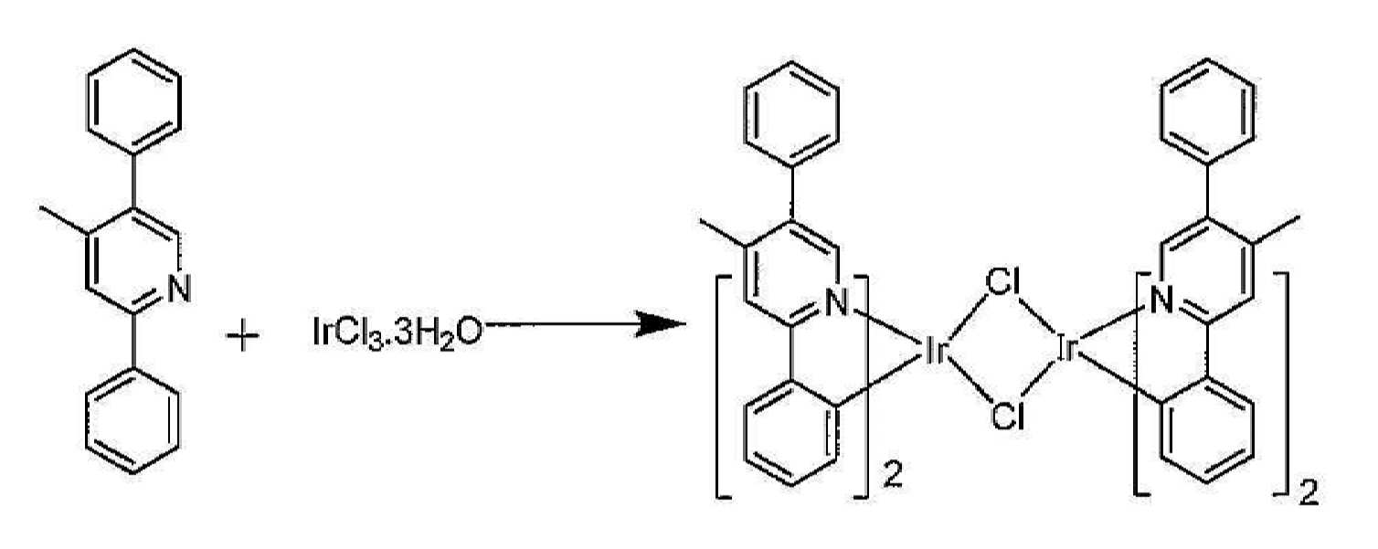
Ir 이량체의 합성. IrCl3-3H2O(7.54 g, 20.4 mol) 및 2,5-디페닐-4-메틸피리딘(15.0 g, 61 mol)을 1 L의 둥근 바닥 플라스크에 투입하였다. 이어서, 2-에톡시에탄올 100 mL 및 물 35 mL을 첨가하였다. 상기 혼합물을 질소 분위기 하에서 16 시간 동안 환류시켰다. 상기 반응 혼합물을 실온으로 냉각시키고, 상기 침전물을 여과시키며, 에탄올에 이어 헥산으로 세척하였다. 이리듐 이량체 13.6 g(99% 수율)을 수득하였다. Synthesis of Ir Dimers. IrCl 3 -3H 2 O (7.54 g, 20.4 mol) and 2,5-diphenyl-4-methylpyridine (15.0 g, 61 mol) were charged to a 1 L round bottom flask. Then 100 mL of 2-ethoxyethanol and 35 mL of water were added. The mixture was refluxed for 16 h under a nitrogen atmosphere. The reaction mixture was cooled to room temperature and the precipitate was filtered off and washed with ethanol followed by hexanes. 13.6 g (99% yield) of iridium dimer were obtained.

Ir 트리플레이트의 합성. 이리듐 이량체 13.3 g을 디클로로메탄 1.5 L에 용해시켰다. 은 트리플레이트(5.11 g, 19.9 mmol)를 이소프로판올 500 mL에 용해시키고, 이리듐 이량체 용액에 첨가하였다. 생성된 혼합물을 실온에서 18 시간 동안 교반하였다. 이어서, 상기 용액을 셀라이트 플러그를 통해 투입하여 염화은을 제거하고, 상기 용매를 진공 하에 증발시켜 이리듐 트리플레이트 17.0 g을 산출하였다. 상기 고체를 추가 정제 없이 다음 단계에서 사용하였다. Synthesis of Ir Triflate. 13.3 g of iridium dimer was dissolved in 1.5 L of dichloromethane. Silver triflate (5.11 g, 19.9 mmol) was dissolved in 500 mL of isopropanol and added to the iridium dimer solution. The resulting mixture was stirred at rt for 18 h. The solution was then introduced through a plug of celite to remove silver chloride and the solvent was evaporated in vacuo to yield 17.0 g of iridium triflate. The solid was used in the next step without further purification.

화합물 21의 합성. 상기 이리듐 트리플레이트(17.0 g, 17.9 mmol) 및 3 몰당량의 2,5-디페닐-4-메틸피리딘(13.1 g, 53.7 mmol)을 1 L의 둥근 바닥 플라스크에 투입하였다. 에탄올 150 mL을 첨가하고, 반응 혼합물을 16 시간 동안 환류시켰다. 셀라이트를 상기 냉각된 용액에 첨가하고, 상기 혼합물을 실리카 겔 2 in 층에 투입하였다. 이어서, 상기 실리카 층을 에탄올(2 x 50 mL)에 이어, 헥산(2 x 50 mL)으로 2회 세척하였다. 이어서, 상기 생성물을 디클로로메탄을 갖는 실리카 겔 플러그를 통해 용리시켰다. 대부부의 디클로로메탄을 진공 하에 제거하고, 상기 생성물을 2-프로판올에 의해 침전시키고, 여과시키며, 헥산으로 세척하고, 건조시켜 생성물 9.69 g(90.6% 수율)을 산출하였다. Synthesis of
실시예 18. 화합물 22의 합성.Example 18. Synthesis of

2-아미노-4-에틸-5-요오도피리딘의 합성. 4-에틸-2-아미노피리딘(10.0 g, 81.9 mmol) 및 아세트산칼륨(8.00 g, 81.9 mmol)을 아세트산 100 mL에 용해시키고, 연속으로 교반시키면서 80℃로 가열하였다. 개별 플라스크에, 요오도모노클로라이드(13.2 g, 81.9 mmol)를 아세트산 30 mL에 용해시키고, 상기 반응 혼합물에 적가하였다. 상기 첨가 완료 후에, 상기 반응 혼합물을 추가 4 시간 동안 가열하였다. 상기 반응 진행을 기체 크로마토그래피 및 HPLC에 의해 모니터링하였다. 상기 반응이 완료될 때, 상기 반응 혼합물을 실온으로 냉각시키고, 포화 아황산나트륨(10 mL)의 수용액으로 켄칭하였다. 아세트산을 진공 하에 제거하고, 상기 잔류물을 아세트산에틸에 용해시키며, 포화 NaHCO3로 중화시켰다. 유기층을 수성층으로부터 분리하고, 상기 용매를 진공 하에 제거하였다. 상기 미정제물을 25% 아세트산에틸/헥산으로 용리시키는 실리카 겔 칼럼 크로마토그래피에 의해 정제하였다. 소정의 생성물 15 g(74% 수율)을 수득하였다. Synthesis of 2-amino-4-ethyl-5-iodopyridine. 4-ethyl-2-aminopyridine (10.0 g, 81.9 mmol) and potassium acetate (8.00 g, 81.9 mmol) were dissolved in 100 mL of acetic acid and heated to 80 ° C. with continuous stirring. In a separate flask, iodomonochloride (13.2 g, 81.9 mmol) was dissolved in 30 mL of acetic acid and added dropwise to the reaction mixture. After completion of the addition, the reaction mixture was heated for an additional 4 hours. The reaction progress was monitored by gas chromatography and HPLC. When the reaction was complete, the reaction mixture was cooled to room temperature and quenched with an aqueous solution of saturated sodium sulfite (10 mL). Acetic acid was removed under vacuum and the residue was dissolved in ethyl acetate and neutralized with saturated NaHCO 3 . The organic layer was separated from the aqueous layer and the solvent removed under vacuum. The crude was purified by silica gel column chromatography eluting with 25% ethyl acetate / hexanes. 15 g (74% yield) of the desired product were obtained.

2-클로로-4-에틸-5-요오도피리딘의 합성. 4-에틸-5-요오도피리딘-2-아민(15.0 g, 60.48 mmol)을 농축 HCL 140 mL에 용해시켰다. NaNO2를 물 40 mL에 용해시키고, 0℃에서 상기 용액에 적가하였다. 상기 반응 혼합물이 0℃ 이상 상승하는 것을 방지하도록 주의하였다. NaNO2 용액 모두를 첨가할 때, 상기 반응 혼합물을 실온으로 가온되도록 하였고, 실온에서 추가 2 시간 동안 교반하였다. 상기 반응 진행을 GC 및 HPLC에 의해 모니터링하였다. 이어서, 상기 반응 혼합물은 0℃로 재냉각시키고, 포화 NaOH를 첨가하여 pH를 pH=12로 조절하였다. 상기 혼합물을 디클로로메탄(2 x 200 mL)으로 추출하고, 용매를 진공 하에 제거하였다. 상기 미정제물을 5% 아세트산에틸/헥산으로 용리시키는 실리카 겔 칼럼 크로마토그래피에 의해 정제하였다. 정제 후에 소정의 생성물 8.0 g(49% 수율)을 수득하였다. Synthesis of 2-chloro-4-ethyl-5-iodopyridine. 4-ethyl-5-iodopyridin-2-amine (15.0 g, 60.48 mmol) was dissolved in 140 mL concentrated HCL. NaNO 2 was dissolved in 40 mL of water and added dropwise to the solution at 0 ° C. Care was taken to prevent the reaction mixture from rising above 0 ° C. When all of the NaNO 2 solution was added, the reaction mixture was allowed to warm to room temperature and stirred at room temperature for an additional 2 hours. The reaction progress was monitored by GC and HPLC. The reaction mixture was then recooled to 0 ° C. and pH was adjusted to pH = 12 by addition of saturated NaOH. The mixture was extracted with dichloromethane (2 x 200 mL) and the solvent was removed in vacuo. The crude was purified by silica gel column chromatography eluting with 5% ethyl acetate / hexanes. After purification, 8.0 g (49% yield) of the desired product were obtained.
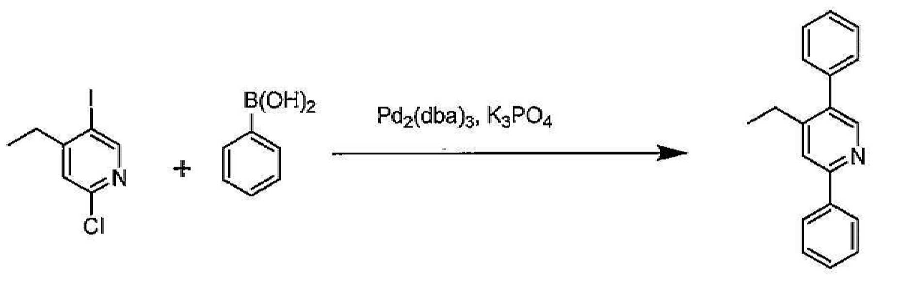
2,5-디페닐-4-에틸피리딘의 합성. 페닐보론산(11.0 g, 90 mmol), 2-클로로-4-에틸-5-요오도피리딘(8.00 g, 30 mmol), 2-디시클로펙실포스피노-2',6'-디메톡시비페닐(492 mg, 1.2 mmol) 및 제3인산칼륨 (20.7 g, 90 mmol), 톨루엔 250 mL 및 물 25 mL를 1 L의 둥근 바닥 플라스크에 투입하였다. 상기 혼합물에 직접 질소를 30 분 동안 버블링한 후, 트리스(디벤질리덴아세톤)디팔라듐(0)(275 mg, 0.3 mmol)을 첨가하였다. 추가 15 분 동안 질소로 버블링하고, 이어서 상기 반응 혼합물을 질소 하에 16 시간 동안 환류로 가열하였다. 상기 반응 완료 후에, 상기 혼합물은 냉각시키고, 상기 유기층을 상기 수성층으로부터 분리하였다. 상기 유기층을 포화 염수로 세척하고, 황산마그네슘 상에서 건조시켰다. 상기 용액을 여과시키고, 용매를 진공 하에 제거하여 회백색 고체를 산출하였다. 이러한 미정제물을 10% 아세트산에틸/헥산으로 용리시키는 실리카 겔 칼럼 크로마토그래피에 의해 정제하였다. 정제 후에 소정의 생성물 7.0 g(90.9% 수율)을 수득하였다. Synthesis of 2,5-diphenyl-4-ethylpyridine. Phenylboronic acid (11.0 g, 90 mmol), 2-chloro-4-ethyl-5-iodopyridine (8.00 g, 30 mmol), 2-dicyclofexylphosphino-2 ', 6'-dimethoxybiphenyl (492 mg, 1.2 mmol) and potassium triphosphate (20.7 g, 90 mmol), 250 mL of toluene and 25 mL of water were charged to a 1 L round bottom flask. Nitrogen was bubbled directly into the mixture for 30 minutes, then tris (dibenzylideneacetone) dipalladium (0) (275 mg, 0.3 mmol) was added. Bubbling with nitrogen for an additional 15 minutes, then the reaction mixture was heated to reflux for 16 hours under nitrogen. After completion of the reaction, the mixture was cooled and the organic layer was separated from the aqueous layer. The organic layer was washed with saturated brine and dried over magnesium sulfate. The solution was filtered and the solvent removed under vacuum to yield an off white solid. This crude was purified by silica gel column chromatography eluting with 10% ethyl acetate / hexanes. 7.0 g (90.9% yield) of the desired product was obtained after purification.
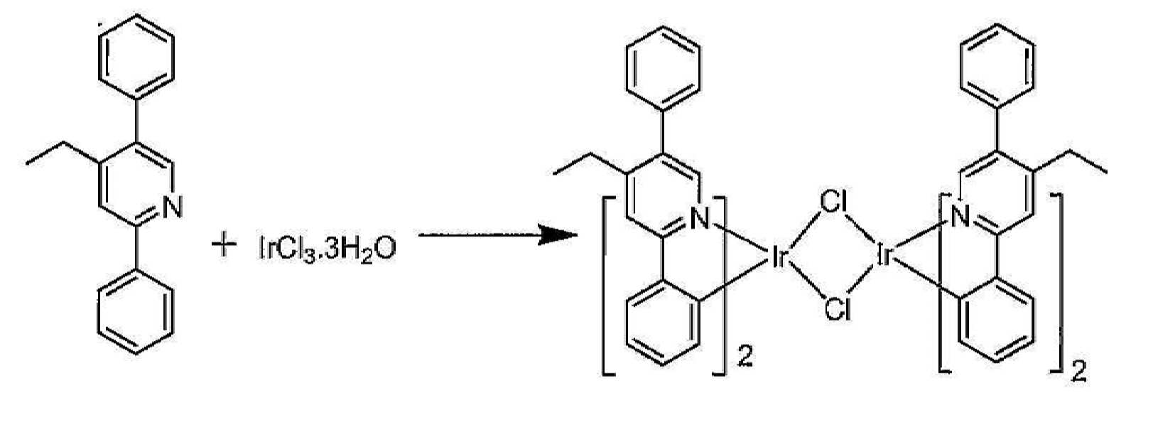
Ir 이량체의 합성. IrCl3-3H2O(1.5 g, 4.41 mmol) 및 2,5-디페닐-4-에틸피리딘(4.0 g, 15.44 mmol)을 250 L의 둥근 바닥 플라스크에 투입하였다. 2-에톡시에탄올 30 mL 및 물 10 mL를 첨가하였다. 상기 혼합물을 질소 분위기 하에서 16 시간 동안 환류시켰다. 이어서, 상기 반응 혼합물을 실온으로 냉각되도록 하고, 침전물을 여과시키며, 메탄올에 이어, 헥산으로 세척하였다. 건조 후, 이리듐 이량체 2.57 g(81% 수율)을 수득하였다. Synthesis of Ir Dimers. IrCl 3 -3H 2 O (1.5 g, 4.41 mmol) and 2,5-diphenyl-4-ethylpyridine (4.0 g, 15.44 mmol) were charged to a 250 L round bottom flask. 30 mL of 2-ethoxyethanol and 10 mL of water were added. The mixture was refluxed for 16 h under a nitrogen atmosphere. The reaction mixture was then allowed to cool to room temperature and the precipitate was filtered off and washed with methanol followed by hexanes. After drying, 2.57 g (81% yield) of iridium dimer were obtained.
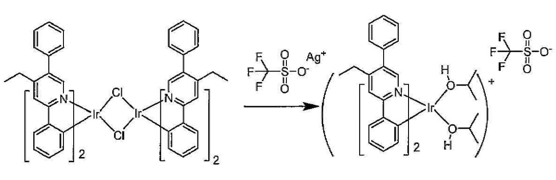
Ir 트리플레이트의 합성. 상기 이리듐 이량체(2.57 g, 1.725 mmol)를 디클로로메탄 250 mL에 용해시켰다. 은 트리플레이트(1.0 g, 3.8 mmol)를 2-프로판올 150 mL에 용해시키고, 상기 이량체 용액에 첨가하였다. 상기 생성된 혼합물을 5 시간 동안 교반하였다. 이어서, 상기 용액을 셀라이트 플러그를 통해 투입하여 염화은을 제거하였다. 상기 용매를 진공 하에 증발시켜 이리듐 트리플레이트 3.2 g을 산출하였다. 상기 고체를 추가 정제 없이 다음 단계에서 사용하였다. Synthesis of Ir Triflate. The iridium dimer (2.57 g, 1.725 mmol) was dissolved in 250 mL of dichloromethane. Silver triflate (1.0 g, 3.8 mmol) was dissolved in 150 mL of 2-propanol and added to the dimer solution. The resulting mixture was stirred for 5 hours. The solution was then introduced through a plug of celite to remove silver chloride. The solvent was evaporated in vacuo to yield 3.2 g of iridium triflate. The solid was used in the next step without further purification.

화합물 22의 합성. 상기 이리듐 인플레이트(3.2 g) 및 2,5-디페닐-4-에틸피리딘(3.2 g)을 250 mL의 둥근 바닥 플라스크에 투입하였다. 에탄올 50 mL을 첨가하고, 혼합물을 16 시간 동안 환류시켰다. 셀라이트를 상기 냉각된 용액에 첨가하고, 상기 혼합물을 실리카 겔 2 in 층에 투입하였다. 이어서, 상기 실리카 층을 에탄올(2 x 100 mL)에 이어, 헥산(2 x 100 mL)으로 2회 세척하였다. 이어서, 상기 생성물을 디클로로메탄을 갖는 실리카 플러그를 통해 용리시켰다. 대부부의 디클로로메탄을 진공 하에 제거하고, 상기 생성물을 2-프로판올에 의해 침전시키고, 여과시키며, 헥산으로 세척하고, 건조시켜 생성물 1.67 g(52.8% 수율)을 산출하였다. Synthesis of
실시예 19. 화합물 23의 합성.Example 19. Synthesis of Compound 23.

2,5-디페닐-6-메틸피리딘의 합성. 페닐보론산(24.3 g, 199.25 mmol), 2,5-디브로모-6-메틸피리딘(10 g, 39.85 mmol), 2-디시클로펙실포스피노-2',6'-디메톡시비페닐(654 mg, 1.5 mmol) 및 제3인산칼륨(27.5 g, 119.5 mmol), 톨루엔 300 mL 및 물 30 mL를 1 L의 둥근 바닥 플라스크에 투입하였다. 상기 혼합물에 직접 질소를 30 분 동안 버블링한 후, 트리스(디벤질리덴아세톤)디팔라듐(0)(364 mg, 0.398 mmol)을 첨가하였다. 추가 15 분 동안 질소로 버블링하고, 이어서 상기 반응 혼합물을 질소 하에 16 시간 동안 환류로 가열하였다. 상기 반응 완료 후에, 상기 혼합물은 냉각시키고, 상기 유기층을 분리하였다. 상기 유기층을 포화 염수 용액으로 세척한 후, 황산마그네슘 상에서 건조시켰다. 상기 용액을 여과시키고, 용매를 진공 하에 제거하였다. 상기 미정제물을 고정상으로서 실리카 겔을 이용하고 이동상으로서 헥산 중 10∼20% 아세트산에틸을 이용하는 칼럼 크로마토그래피에 의해 정제하였다. 정제 후에 소정의 생성물 9.0 g(92.7% 수율)을 수득하였다. Synthesis of 2,5-diphenyl-6-methylpyridine. Phenylboronic acid (24.3 g, 199.25 mmol), 2,5-dibromo-6-methylpyridine (10 g, 39.85 mmol), 2-dicyclopexylphosphino-2 ', 6'-dimethoxybiphenyl ( 654 mg, 1.5 mmol) and potassium triphosphate (27.5 g, 119.5 mmol), 300 mL of toluene and 30 mL of water were charged to a 1 L round bottom flask. Nitrogen was bubbled directly into the mixture for 30 minutes and then tris (dibenzylideneacetone) dipalladium (0) (364 mg, 0.398 mmol) was added. Bubbling with nitrogen for an additional 15 minutes, then the reaction mixture was heated to reflux for 16 hours under nitrogen. After completion of the reaction, the mixture was cooled and the organic layer was separated. The organic layer was washed with saturated brine solution and then dried over magnesium sulfate. The solution was filtered and the solvent removed in vacuo. The crude was purified by column chromatography using silica gel as the stationary phase and 10-20% ethyl acetate in hexane as the mobile phase. 9.0 g (92.7% yield) of the desired product was obtained after purification.

Ir 이량체의 합성. IrCl3-3H2O(1.6 g, 4.66 mmol) 및 2,5-디페닐-6-메틸피리딘(4.0 g, 16.31mmol)을 250 mL의 둥근 바닥 플라스크에 투입하였다. 2-에톡시에탄올 45 mL 및 물 15 mL를 첨가하였다. 상기 혼합물을 질소 하에서 16 시간 동안 환류시켰다. 이어서, 상기 반응 혼합물을 실온으로 냉각되도록 하였다. 상기 침전물을 여과시키고, 헥산에 의해 세척한 후, 메탄올로 세척하였다. 건조 후, 이량체 2.75 g(84.6% 수율)을 수득하였다. Synthesis of Ir Dimers. IrCl 3 -3H 2 O (1.6 g, 4.66 mmol) and 2,5-diphenyl-6-methylpyridine (4.0 g, 16.31 mmol) were charged to a 250 mL round bottom flask. 45 mL of 2-ethoxyethanol and 15 mL of water were added. The mixture was refluxed under nitrogen for 16 hours. The reaction mixture was then allowed to cool to room temperature. The precipitate was filtered off, washed with hexanes and then with methanol. After drying, 2.75 g (84.6% yield) of dimers were obtained.

Ir 트리플레이트의 합성. 상기 이리듐 이량체(2.75 g, 2.2 mmol)를 디클로로메탄 200 mL에 용해시켰다. 은 트리플레이트(1.19 g, 4.6 mmol)를 메탄올 100 mL에 용해시키고, 이리듐 이량체 용액에 첨가하였다. 상기 생성된 혼합물을 5 시간 동안 교반하였다. 이어서, 상기 용액을 셀라이트 플러그에 통과시켜 염화은을 제거하였다. 상기 용매를 진공 하에 증발시켜 이리듐 트리플레이트 3.5 g을 산출하였다. 상기 고체를 추가 정제 없이 다음 단계에서 사용하였다. Synthesis of Ir Triflate. The iridium dimer (2.75 g, 2.2 mmol) was dissolved in 200 mL of dichloromethane. Silver triflate (1.19 g, 4.6 mmol) was dissolved in 100 mL of methanol and added to the iridium dimer solution. The resulting mixture was stirred for 5 hours. The solution was then passed through a plug of celite to remove silver chloride. The solvent was evaporated in vacuo to yield 3.5 g of iridium triflate. The solid was used in the next step without further purification.

화합물 23의 합성. 상기 이리듐 트리플레이트(3.0 g) 및 2,5-디페닐-6-메틸피리딘(3.0 g)을 100 mL의 둥근 바닥 플라스크에 투입하였다. 상기 고체 혼합물을 130℃로 16 시간 동안 가열하였다. 냉각 후, 상기 반응 혼합물을 디클로로메탄 200 mL에 용해시켰다. 이어서, 상기 용액을 2 in의 실리카 겔 플러그에 통과시켰다. 상기 용매를 진공 하에 제거하고, 잔류물을 이동상으로서 디클로로메탄에 의해 실리카 겔을 이용하여 크로마토그래피 처리하였다. 대부부의 용매를 증발시키고, 상기 생성물을 2-프로판올에 의해 침전시키며, 여과시키고, 헥산으로 세척하며, 건조시켜 생성물 2.65 g(71% 수율)을 산출하였다. Synthesis of Compound 23. The iridium triflate (3.0 g) and 2,5-diphenyl-6-methylpyridine (3.0 g) were charged to a 100 mL round bottom flask. The solid mixture was heated to 130 ° C. for 16 hours. After cooling, the reaction mixture was dissolved in 200 mL of dichloromethane. The solution was then passed through a 2 in silica gel plug. The solvent was removed in vacuo and the residue was chromatographed using silica gel with dichloromethane as mobile phase. Most solvents were evaporated and the product was precipitated with 2-propanol, filtered, washed with hexanes and dried to yield 2.65 g (71% yield) of product.
실시예 20. 화합물 24의 합성.Example 20. Synthesis of Compound 24.
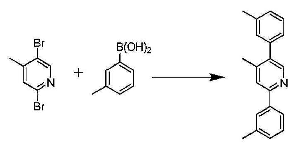
2,5-(m-톨릴)-4-메틸피리딘의 합성. m-톨릴보론산 에스테르(17.9 g, 132 mmol), 2,5-디브로모-4-메틸피리딘(11.0 g, 44.0 mmol), 2-디시클로펙실포스피노-2',6'-디메톡시비페닐(726 mg, 1.77 mmol) 및 제3인산칼륨 일수화물(30 g, 130 mmol), 톨루엔 143 mL 및 물 33 mL를 500 mL의 둥근 바닥 플라스크에 투입하였다. 상기 혼합물에 직접 질소를 30 분 동안 버블링한 후, 트리스(디벤질리덴아세톤)디팔라듐(0)(394 mg, 43 mmol)을 첨가하였다. 추가 15 분 동안 질소로 버블링하고, 이어서 상기 반응 혼합물을 질소 하에 16 시간 동안 환류로 가열하였다. 상기 혼합물을 실온으로 냉각되도록 하고, 유기상을 상기 수성상으로부터 분리하였다. 상기 유기층을 포화 염수 용액으로 세척한 후, 황산마그네슘 상에서 건조시켰다. 상기 용액을 여과시키고, 용매를 진공 하에 제거하여 회백색 생성물을 산출하였다. 상기 미정제물을 고정상으로서 실리카 겔을 이용하고 이동상으로서 헥산 중 10% 아세트산에틸을 이용하는 칼럼 크로마토그래피에 의해 정제하였다. 정제 후에 소정의 생성물 11.2 g을 수득하였다. (93.3% 수율). Synthesis of 2,5- (m-tolyl) -4-methylpyridine. m-tolylboronic acid ester (17.9 g, 132 mmol), 2,5-dibromo-4-methylpyridine (11.0 g, 44.0 mmol), 2-dicyclopexylphosphino-2 ', 6'-dimethock Cibiphenyl (726 mg, 1.77 mmol) and potassium triphosphate monohydrate (30 g, 130 mmol), 143 mL of toluene and 33 mL of water were charged into a 500 mL round bottom flask. Nitrogen was bubbled directly into the mixture for 30 minutes, then tris (dibenzylideneacetone) dipalladium (0) (394 mg, 43 mmol) was added. Bubbling with nitrogen for an additional 15 minutes, then the reaction mixture was heated to reflux for 16 hours under nitrogen. The mixture was allowed to cool to room temperature and the organic phase was separated from the aqueous phase. The organic layer was washed with saturated brine solution and then dried over magnesium sulfate. The solution was filtered and the solvent removed in vacuo to yield an off white product. The crude was purified by column chromatography using silica gel as stationary phase and 10% ethyl acetate in hexane as mobile phase. After purification, 11.2 g of the desired product were obtained. (93.3% yield).

Ir 이량체의 합성. IrCl3-3H2O(1.8 g, 4.86 mmol) 및 2,5-디톨릴-4-메틸피리딘(4.0 g, 14.6 mmol)을 100 mL의 둥근 바닥 플라스크에 투입하였다. 2-에톡시에탄올 24 mL 및 물 8 mL를 첨가하였다. 상기 혼합물을 질소 분위기 하에서 16 시간 동안 환류시켰다. 이어서, 상기 반응 혼합물을 실온으로 냉각되도록 하였다. 상기 침전물을 여과시키고, 헥산에 의해 세척한 후, 메탄올로 세척하였다. 건조 후, 이리듐 이량체 3.0 g(79.6% 수율)을 수득하였다. Synthesis of Ir Dimers. IrCl 3 -3H 2 O (1.8 g, 4.86 mmol) and 2,5-ditolyl-4-methylpyridine (4.0 g, 14.6 mmol) were charged to a 100 mL round bottom flask. 24 mL 2-ethoxyethanol and 8 mL water were added. The mixture was refluxed for 16 h under a nitrogen atmosphere. The reaction mixture was then allowed to cool to room temperature. The precipitate was filtered off, washed with hexanes and then with methanol. After drying, 3.0 g (79.6% yield) of iridium dimer were obtained.
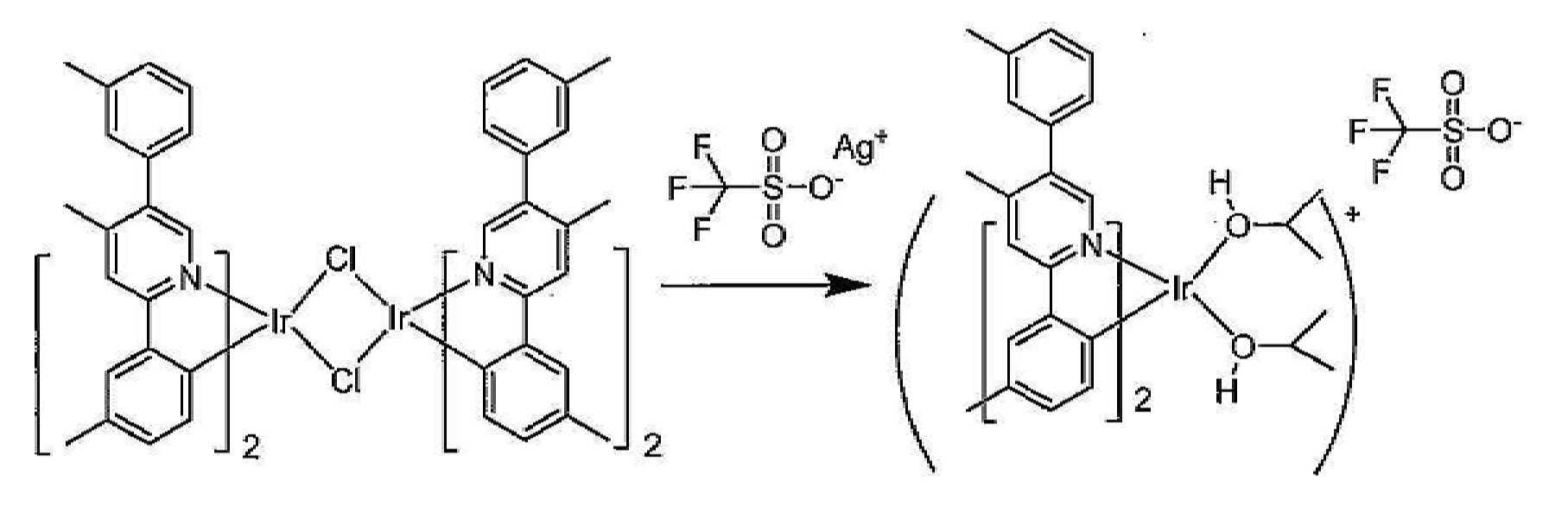
Ir 트리플레이트의 합성. 이리듐 이량체 3.0 g을 디클로로메탄 380 mL에 용해시켰다. 은 트리플레이트(l.Og, 4.08 mmol)를 이소프로판올 20 mL에 용해시키고, 이리듐 이량체 용액에 첨가하였다. 상기 생성된 혼합물을 5 시간 동안 교반하였다. 이어서, 상기 용액을 셀라이트 플러그를 통해 투입하여 염화은을 제거하였다. 상기 용매를 진공 하에 증발시켜 이리듐 트리플레이트 2.7 g을 산출하였다. 상기 고체를 추가 정제 없이 다음 단계에서 사용하였다. Synthesis of Ir Triflate. 3.0 g of iridium dimer was dissolved in 380 mL of dichloromethane. Silver triflate (l.Og, 4.08 mmol) was dissolved in 20 mL of isopropanol and added to the iridium dimer solution. The resulting mixture was stirred for 5 hours. The solution was then introduced through a plug of celite to remove silver chloride. The solvent was evaporated in vacuo to yield 2.7 g of iridium triflate. The solid was used in the next step without further purification.

화합물 24의 합성. 상기 이리듐 인플레이트(2.7 g, 2.95 mmol) 및 2,5-디톨릴-4-메틸피리딘(3.6 g, 13.2 mmol)을 250 mL의 둥근 바닥 플라스크에 투입하였다. 에탄올 100 mL을 첨가하고, 혼합물을 16 시간 동안 환류시켰다. 셀라이트를 상기 냉각된 용액에 첨가하고, 상기 혼합물을 실리카 겔 2 in 층에 투입하였다. 이어서, 상기 실리카 층을 에탄올(2 x 50 mL)에 이어, 헥산(2 x 50 mL)으로 2회 세척하였다. 이어서, 상기 생성물을 디클로로메탄을 갖는 실리카 플러그를 통해 용리시켰다. 대부부의 디클로로메탄을 진공 하에 제거하고, 상기 생성물을 2-프로판올에 의해 침전시키고, 여과시키며, 헥산으로 세척하고, 건조시켜 생성물 2.4 g(80.6% 수율)을 산출하였다. Synthesis of Compound 24. The iridium inplate (2.7 g, 2.95 mmol) and 2,5-ditolyl-4-methylpyridine (3.6 g, 13.2 mmol) were charged to a 250 mL round bottom flask. 100 mL of ethanol was added and the mixture was refluxed for 16 h. Celite was added to the cooled solution and the mixture was poured into a
실시예 21. 화합물 25의 합성. Example 21. Synthesis of

2-페닐-5-(m-톨릴)피리딘의 합성. 2-메틸페닐 보론산(5.1 g, 37.59 mmol), 2-페닐-5-브로모피리딘(8.0 g, 34.17 mmol), 2-디시클로펙실포스피노-2',6'-디메톡시비페닐(561 mg, 1.366 mmol) 및 제3인산칼륨(23.50 g, 102.51 mmol), 톨루엔 250 mL 및 물 25 mL를 1 L의 둥근 바닥 플라스크에 투입하였다. 상기 혼합물에 직접 질소를 30 분 동안 버블링한 후, 트리스(디벤질리덴아세톤)디팔라듐(0)(312 mg, 0.341 mmol)을 첨가하였다. 이어서, 추가 15 분 동안 질소로 버블링하고, 상기 반응 혼합물을 질소 하에 16 시간 동안 환류로 가열하였다. 상기 혼합물은 냉각시키고, 상기 유기층을 상기 수성층으로부터 분리하였다. 상기 유기층을 포화 염수 용액으로 세척하고, 황산마그네슘 상에서 건조시키며, 여과시키고, 용매를 진공 하에 제거하여 미정제물로서 회백색 고체를 산출하였다. 상기 미정제물을 고정상으로서 실리카 겔을 이용하고 이동상으로서 헥산 중 2% 아세트산에틸을 이용하는 칼럼 크로마토그래피에 의해 정제하였다. 정제 후에 소정의 생성물 6.5 g(78% 수율)을 수득하였다. Synthesis of 2-phenyl-5- (m-tolyl) pyridine. 2-methylphenyl boronic acid (5.1 g, 37.59 mmol), 2-phenyl-5-bromopyridine (8.0 g, 34.17 mmol), 2-dicyclopexylphosphino-2 ', 6'-dimethoxybiphenyl (561 mg, 1.366 mmol) and potassium triphosphate (23.50 g, 102.51 mmol), 250 mL of toluene and 25 mL of water were charged to a 1 L round bottom flask. Nitrogen was bubbled directly into the mixture for 30 minutes and then tris (dibenzylideneacetone) dipalladium (0) (312 mg, 0.341 mmol) was added. It was then bubbled with nitrogen for an additional 15 minutes and the reaction mixture was heated to reflux for 16 hours under nitrogen. The mixture was cooled and the organic layer was separated from the aqueous layer. The organic layer was washed with saturated brine solution, dried over magnesium sulfate, filtered and the solvent removed in vacuo to yield an off white solid as a crude. The crude was purified by column chromatography using silica gel as the stationary phase and 2% ethyl acetate in hexane as the mobile phase. 6.5 g (78% yield) of the desired product was obtained after purification.

화합물 25의 합성. 상기 이리듐 트리플레이트(화합물의 1의 합성으로부터)(3.25 g) 및 2-페닐-5-톨릴피리딘(3.2 g)을 250 mL의 둥근 바닥 플라스크에 투입하였다. 메탄올과 에탄올의 50:50 혼합물(100 mL)을 첨가하고, 상기 혼합물을 16 시간 동안 환류시켰다. 셀라이트를 상기 냉각된 용액에 첨가하고, 상기 혼합물을 실리카 겔 2 in 층에 투입하였다. 이어서, 상기 실리카 층을 에탄올(2 x 100 mL)에 이어, 헥산(2 x 100 mL)으로 2회 세척하였다. 이어서, 상기 생성물을 디클로로메탄을 갖는 실리카 플러그를 통해 용리시켰다. 상기 디클로로메탄을 진공 하에 제거하여 성분들의 혼합물로서 미정제 생성물을 산출하였다. 소정의 화합물을 분리시키고, 고정상으로서 실리카 겔을 이용하고 이동상으로서 1:1의 디클로로메탄/헥산을 이용하는 칼럼 크로마토그래피에 의해 단리시켰다. 정제 후에 소정의 생성물 0.53 g(15.6 % 수율)을 수득하였다. Synthesis of
실시예 22. 화합물 26의 합성. Example 22. Synthesis of Compound 26.
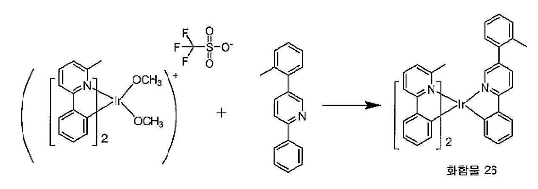
화합물 26의 합성. 상기 이리듐 인플레이트(3.25 g) 및 2-페닐-5-톨릴피리딘(3.2 g)을 250 mL의 둥근 바닥 플라스크에 투입하였다. 메탄올과 에탄올의 50:50 혼합물(100 mL)을 첨가하고, 상기 혼합물을 16 시간 동안 환류시켰다. 셀라이트를 상기 냉각된 용액에 첨가하고, 상기 혼합물을 실리카 겔 2 in 층에 투입하였다. 이어서, 상기 실리카 층을 에탄올(2 x 100 mL)에 이어, 헥산(2 x 100 mL)으로 2회 세척하였다. 이어서, 상기 생성물을 디클로로메탄을 갖는 실리카 플러그를 통해 용리시켰다. 상기 디클로로메탄을 진공 하에 제거하여 소정의 화합물로서 미정제 생성물을 산출하였다. 상기 화합물을 고정상으로서 실리카 겔을 이용하고 이동상으로서 1:1의 디클로로메탄/헥산을 이용하는 칼럼 크로마토그래피에 의해 추가로 정제하였다. 정제 후에 소정의 생성물 3.38 g(100% 수율)을 수득하였다. Synthesis of Compound 26. The iridium inplate (3.25 g) and 2-phenyl-5-tolylpyridine (3.2 g) were charged to a 250 mL round bottom flask. A 50:50 mixture of methanol and ethanol (100 mL) was added and the mixture was refluxed for 16 h. Celite was added to the cooled solution and the mixture was poured into a
실시예 23. 화합물 27의 합성.Example 23. Synthesis of Compound 27.

2-페닐-4-클로로피리딘의 합성. 2,4-디클로로피리딘(10 g, 67.57 mmol), 페닐보론산(9.0 g, 74.32 mmol), 및 탄산칼륨(28 g, 202.70 mmol), 디메톡시 에탄 300 mL 및 물 30 mL를 1 L의 둥근 바닥 플라스크에 투입하였다. 상기 혼합물에 질소를 30분 동안 직접 버블링하였다. 테트라키스(트리페닐포스핀)팔라듐(0)(780 mg, 0.675 mmol)을 첨가하고, 상기 반응 혼합물에 질소를 추가 15 분 동안 버블링하였다. 이어서, 상기 혼합물을 질소 하에서 16 시간 동안 환류로 가열하였다. 이어서, 반응을 실온으로 냉각되도록 하고, 아세트산에틸 및 물로 희석시켰다. 유기층 및 수성층을 분리시고, 수성층을 아세트산에틸로 추출하였다. 상기 유기층을 배합하고, 포화 염수 용액으로 세척하였다. 이어서, 상기 유기층을 황산마그네슘 상에서 건조시키며, 여과시키고, 용매를 진공 하에 제거하여 미정제물로서 회백색 고체를 산출하였다. 상기 미정제물을 고정상으로서 실리카 겔을 이용하고 이동상으로서 헥산 중 2% 아세트산에틸을 이용하는 칼럼 크로마토그래피에 의해 정제하였다. 정제 후에 소정의 생성물 8.0 g(54% 수율)을 수득하였다. 정제 후에 소정의 생성물 11.5 g(89.77% 수율)을 수득하였다. Synthesis of 2-phenyl-4-chloropyridine. 1
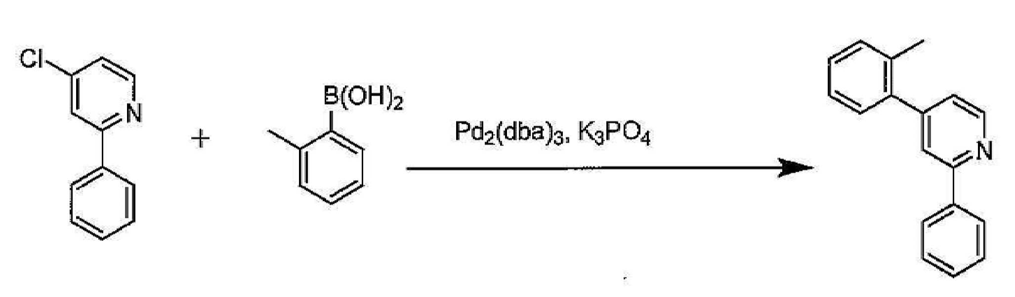
2-페닐-4-(m-톨릴)피리딘의 합성. 2-메틸페닐 보론산(6.3 g, 46.40 mmol), 2-페닐-4-클로로피리딘(8.0 g, 42.18 mmol), 2-디시클로펙실포스피노-2',6'-디메톡시비페닐(692 mg, 1.68 mmol) 및 제3인산칼륨(29.10 g, 126.54 mmol), 톨루엔 250 mL 및 물 25 mL를 500 mL의 둥근 바닥 플라스크에 투입하였다. 상기 혼합물에 직접 질소를 30 분 동안 버블링한 후, 트리스(디벤질리덴아세톤)디팔라듐(0)(386 mg, 0.421 mmol)을 첨가하였다. 이어서, 추가 15 분 동안 질소로 버블링한 후, 상기 반응 혼합물을 질소 하에 16 시간 동안 환류로 가열하였다. 상기 혼합물은 냉각시키고, 상기 유기층을 상기 수성층으로부터 분리하였다. 상기 유기층을 포화 염수 용액으로 세척하고, 황산마그네슘 상에서 건조시키며, 여과시키고, 용매를 진공 하에 제거하여 미정제물로서 회백색 고체를 산출하였다. 상기 미정제물을 고정상으로서 실리카 겔을 이용하고 이동상으로서 헥산 중 2% 아세트산에틸을 이용하는 칼럼 크로마토그래피에 의해 정제하였다. 정제 후에 소정의 생성물 8.0 g(77.4% 수율)을 수득하였다. Synthesis of 2-phenyl-4- (m-tolyl) pyridine. 2-methylphenyl boronic acid (6.3 g, 46.40 mmol), 2-phenyl-4-chloropyridine (8.0 g, 42.18 mmol), 2-dicyclofexylphosphino-2 ', 6'-dimethoxybiphenyl (692 mg , 1.68 mmol) and potassium triphosphate (29.10 g, 126.54 mmol), 250 mL of toluene and 25 mL of water were charged into a 500 mL round bottom flask. Nitrogen was bubbled directly into the mixture for 30 minutes and then tris (dibenzylideneacetone) dipalladium (0) (386 mg, 0.421 mmol) was added. After bubbling with nitrogen for an additional 15 minutes, the reaction mixture was heated to reflux for 16 hours under nitrogen. The mixture was cooled and the organic layer was separated from the aqueous layer. The organic layer was washed with saturated brine solution, dried over magnesium sulfate, filtered and the solvent removed in vacuo to yield an off white solid as a crude. The crude was purified by column chromatography using silica gel as the stationary phase and 2% ethyl acetate in hexane as the mobile phase. After purification, 8.0 g (77.4% yield) of the desired product were obtained.

화합물 27의 합성. 상기 이리듐 인플레이트(4.0 g) 및 2-페닐-4-o-톨릴피리딘(4.0 g)을 250 mL의 둥근 바닥 플라스크에 투입하였다. 메탄올과 에탄올의 50:50 혼합물(100 mL)을 첨가하고, 상기 혼합물을 16 시간 동안 환류시켰다. 셀라이트를 상기 냉각된 용액에 첨가하고, 상기 혼합물을 실리카 겔 2 in 층에 투입하였다. 이어서, 상기 실리카 층을 에탄올(2 x 100 mL)에 이어, 헥산(2 x 100 mL)으로 2회 세척하였다. 이어서, 상기 생성물을 디클로로메탄을 갖는 실리카 플러그를 통해 용리시켰다. 상기 디클로로메탄을 진공 하에 제거하여 성분들의 혼합물로서 미정제 생성물을 산출하였다. 소정의 화합물을 분리시키고, 고정상으로서 실리카 겔을 이용하고 이동상으로서 1:1의 디클로로메탄/헥산을 이용하는 칼럼 크로마토그래피에 의해 단리시켰다. 정제 후에 소정의 생성물 2.0 g(48% 수율)을 수득하였다. Synthesis of Compound 27. The iridium inplate (4.0 g) and 2-phenyl-4-o-tolylpyridine (4.0 g) were charged to a 250 mL round bottom flask. A 50:50 mixture of methanol and ethanol (100 mL) was added and the mixture was refluxed for 16 h. Celite was added to the cooled solution and the mixture was poured into a
실시예 24. 화합물 28의 합성.Example 24. Synthesis of Compound 28.

화합물 28의 합성. 상기 이리듐 인플레이트(4.0 g) 및 2-페닐-4-o-톨릴피리딘(4.0 g)을 250 mL의 둥근 바닥 플라스크에 투입하였다. 메탄올과 에탄올의 50:50 혼합물(100 mL)을 첨가하고, 상기 혼합물을 16 시간 동안 환류시켰다. 셀라이트를 상기 냉각된 용액에 첨가하고, 상기 혼합물을 실리카 겔 2 in 층에 투입하였다. 이어서, 상기 실리카 층을 에탄올(2 x 100 mL)에 이어, 헥산(2 x 100 mL)으로 2회 세척하였다. 이어서, 상기 생성물을 디클로로메탄을 갖는 실리카 플러그를 통해 용리시켰다. 상기 디클로로메탄을 진공 하에 제거하여 소정의 화합물로서 미정제 생성물을 산출하였다. 상기 화합물을 고정상으로서 실리카 겔을 이용하고 이동상으로서 1:1의 디클로로메탄/헥산을 이용하는 칼럼 크로마토그래피에 의해 추가로 정제하였다. 정제 후에 소정의 생성물 3.6 g(86.6% 수율)을 수득하였다. Synthesis of Compound 28. The iridium inplate (4.0 g) and 2-phenyl-4-o-tolylpyridine (4.0 g) were charged to a 250 mL round bottom flask. A 50:50 mixture of methanol and ethanol (100 mL) was added and the mixture was refluxed for 16 h. Celite was added to the cooled solution and the mixture was poured into a
실시예 25. 화합물 29의 합성.Example 25. Synthesis of

화합물 29의 합성. 상기 이리듐 인플레이트(4.0 g, 4.62 mmol) 및 2-페닐피리딘(2.15 g, 13.87 mmol)을 100 mL의 둥근 바닥 플라스크에 투입하였다. 메탄올과 에탄올의 50:50 혼합물(60 mL)을 첨가하고, 상기 혼합물을 16 시간 동안 환류시켰다. 셀라이트를 상기 냉각된 용액에 첨가하고, 상기 혼합물을 실리카 겔 2 in 층에 투입하였다. 이어서, 상기 실리카 층을 에탄올(2 x 50 mL)에 이어, 헥산(2 x 50 mL)으로 2회 세척하였다. 이어서, 상기 생성물을 디클로로메탄을 갖는 실리카 플러그를 통해 용리시켰다. 상기 디클로로메탄을 진공 하에 제거하여 성분들의 혼합물로서 미정제 생성물을 산출하였다. 소정의 화합물을 분리시키고, 고정상으로서 실리카 겔을 이용하고 이동상으로서 1:1의 디클로로메탄/헥산을 이용하는 칼럼 크로마토그래피에 의해 단리시켰다. 정제 후에 소정의 생성물 1.1 g(31.6% 수율)을 수득하였다. Synthesis of
실시예 26. 화합물 30의 합성.Example 26. Synthesis of
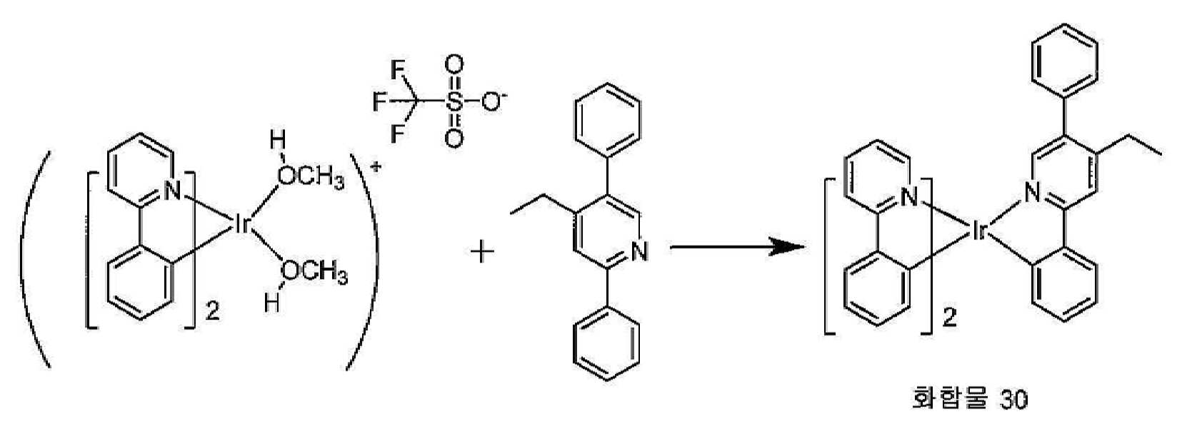
화합물 30의 합성. 상기 이리듐 트리플레이트(3.2 g) 및 2,5-디페닐-4-에틸피리딘(3.2 g)을 250 mL의 둥근 바닥 플라스크에 투입하였다. 에탄올 50 mL을 첨가하고, 혼합물을 16 시간 동안 환류시켰다. 셀라이트를 상기 냉각된 용액에 첨가하고, 상기 혼합물을 실리카 겔 2 in 층에 투입하였다. 이어서, 상기 실리카 층을 에탄올(2 x 50 mL)에 이어, 헥산(2 x 50 mL)으로 2회 세척하였다. 이어서, 상기 생성물을 디클로로메탄을 갖는 실리카 플러그를 통해 용리시켰다. 상기 디클로로메탄을 진공 하에 제거하여 성분들의 혼합물로서 미정제 생성물을 산출하였다. 소정의 화합물을 분리시키고, 고정상으로서 실리카 겔을 이용하고 이동상으로서 1:1의 디클로로메탄/헥산을 이용하는 칼럼 크로마토그래피에 의해 단리시켰다. 정제 후에 소정의 생성물 1.22 g(31.6% 수율)을 수득하였다. Synthesis of
실시예 27. 화합물 31의 합성.Example 27. Synthesis of
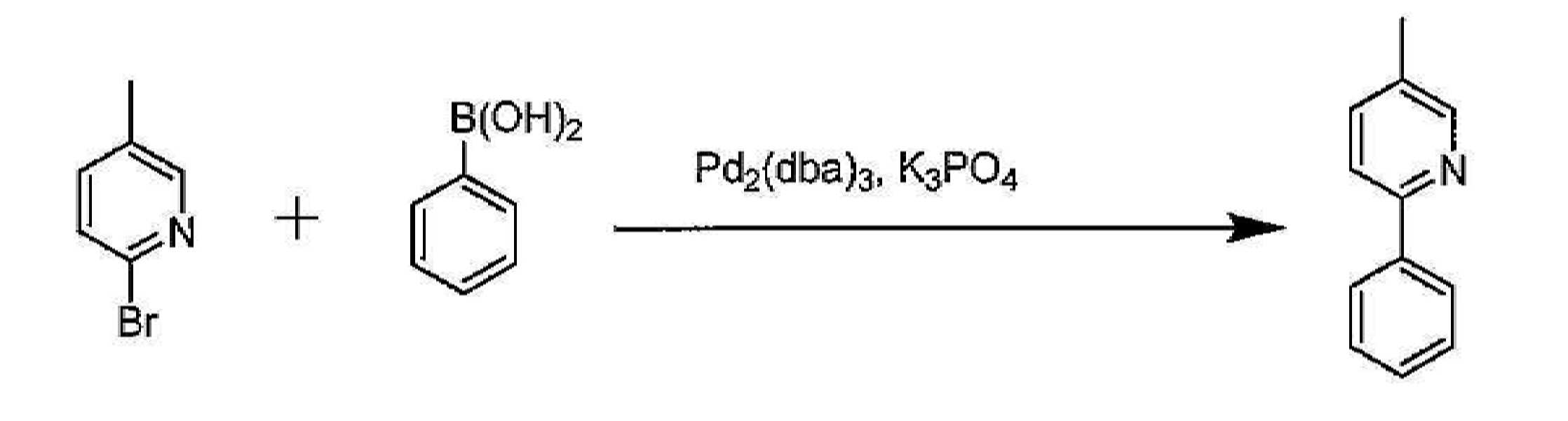
2-페닐-5-메틸피리딘의 합성. 2-브로모-5-메틸피리딘(11.25 g, 65.39 mmol), 페닐보론산(9.5 g, 78.47 mmol), 2-디시클로펙실포스피노-2',6'-디메톡시비페닐(1.0 g, 2.61 mmol) 및 제3인산칼륨(45 g, 196.17 mmol), 톨루엔 250 mL 및 물 25 mL를 500 L의 둥근 바닥 플라스크에 투입하였다. 상기 혼합물에 직접 질소를 30 분 동안 버블링한 후, 트리스(디벤질리덴아세톤)디팔라듐(0)(598 mg, 0.653 mmol)을 첨가하였다. 추가 15 분 동안 질소로 버블링하고, 이어서 상기 반응 혼합물을 질소 하에 16 시간 동안 환류로 가열하였다. 상기 혼합물은 냉각시키고, 상기 유기층을 상기 수성층으로부터 분리하였다. 상기 유기층을 포화 염수 용액으로 세척하고, 황산마그네슘 상에서 건조시키며, 여과시키고, 용매를 진공 하에 제거하여 미정제물로서 회백색 고체를 산출하였다. 상기 미정제물을 고정상으로서 실리카 겔을 이용하고 이동상으로서 헥산 중 5∼10% 아세트산에틸을 이용하는 칼럼 크로마토그래피에 의해 정제하였다. 정제 후에 소정의 생성물 10.11 g(92% 수율)을 수득하였다. Synthesis of 2-phenyl-5-methylpyridine. 2-bromo-5-methylpyridine (11.25 g, 65.39 mmol), phenylboronic acid (9.5 g, 78.47 mmol), 2-dicyclopexylphosphino-2 ', 6'-dimethoxybiphenyl (1.0 g, 2.61 mmol) and potassium triphosphate (45 g, 196.17 mmol), 250 mL of toluene and 25 mL of water were charged to a 500 L round bottom flask. Nitrogen was bubbled directly into the mixture for 30 minutes, then tris (dibenzylideneacetone) dipalladium (0) (598 mg, 0.653 mmol) was added. Bubbling with nitrogen for an additional 15 minutes, then the reaction mixture was heated to reflux for 16 hours under nitrogen. The mixture was cooled and the organic layer was separated from the aqueous layer. The organic layer was washed with saturated brine solution, dried over magnesium sulfate, filtered and the solvent removed in vacuo to yield an off white solid as a crude. The crude was purified by column chromatography using silica gel as the stationary phase and 5-10% ethyl acetate in hexane as the mobile phase. After purification, 10.11 g (92% yield) of the desired product were obtained.

Ir 이량체의 합성. 2-페닐-5-메틸피리딘(10.11 g, 59.8 mmol) 및 IrCl3-3H2O(6.0 g, 17 mmol)를 250 mL의 둥근 플라스크 중 2-에톡시에탄올 90 mL 및 물 30 mL에 용해시켰다. 상기 반응 혼합물을 질소 하에서 16 시간 동안 환류시켰다. 이어서, 상기 반응 혼합물을 실온으로 냉각되도록 하고, 침전물을 여과시키며, 메탄올에 이어, 헥산으로 세척하였다. 이어서, 상기 이리듐 이량체를 진공 하에 건조시키고, 다음 단계에서 추가 정제 없이 사용하였다. 진공 건조 후에 이량체 8.75 g(91.0% 수율)을 수득하였다. Synthesis of Ir Dimers. 2-phenyl-5-methylpyridine (10.11 g, 59.8 mmol) and IrCl 3 -3H 2 O (6.0 g, 17 mmol) were dissolved in 90 mL of 2-ethoxyethanol and 30 mL of water in a 250 mL round flask. . The reaction mixture was refluxed under nitrogen for 16 hours. The reaction mixture was then allowed to cool to room temperature and the precipitate was filtered off and washed with methanol followed by hexanes. The iridium dimer was then dried under vacuum and used without further purification in the next step. 8.75 g (91.0% yield) of dimers were obtained after vacuum drying.

Ir 트리플레이트의 합성. 상기 이리듐 이량체(8.74 g, 7.75 mmol)를 디클로로메탄 1.0 L에 용해시켰다. 은 트리플레이트(4.18 g, 16.27 mmol)를 메탄올 500 mL에 용해시키고, 이리듐 이량체 용액에 첨가하였다. 상기 생성된 혼합물을 18 시간 동안 교반하였다. 이어서, 상기 용액을 셀라이트 플러그에 통과시켜 염화은을 제거하고, 상기 용매를 증발시켜 이리듐 트리플레이트 4.0 g을 산출하였다. 상기 고체를 추가 정제 없이 다음 단계에서 사용하였다. Synthesis of Ir Triflate. The iridium dimer (8.74 g, 7.75 mmol) was dissolved in 1.0 L of dichloromethane. Silver triflate (4.18 g, 16.27 mmol) was dissolved in 500 mL of methanol and added to the iridium dimer solution. The resulting mixture was stirred for 18 hours. The solution was then passed through a plug of celite to remove silver chloride and the solvent was evaporated to yield 4.0 g of iridium triflate. The solid was used in the next step without further purification.

화합물 31의 합성. 상기 이리듐 트리플레이트(4.0 g) 및 2,5-디페닐-4-메틸피리딘(4.0 g)을 250 mL의 둥근 바닥 플라스크에 투입하였다. 메탄올과 에탄올의 50:50 혼합물(80 mL)을 첨가하고, 상기 혼합물을 16 시간 동안 환류시켰다. 셀라이트를 상기 냉각된 용액에 첨가하고, 상기 혼합물을 실리카 겔 2 in 층에 투입하였다. 이어서, 상기 실리카 층을 에탄올(2 x 100 mL)에 이어, 헥산(2 x 100 mL)으로 2회 세척하였다. 이어서, 상기 생성물을 디클로로메탄을 갖는 실리카 플러그를 통해 용리시켰다. 상기 디클로로메탄을 진공 하에 제거하여 성분들의 혼합물로서 미정제 생성물을 산출하였다. 소정의 화합물을 분리시키고, 고정상으로서 실리카 겔을 이용하고 이동상으로서 1:1의 디클로로메탄/헥산을 이용하는 칼럼 크로마토그래피에 의해 단리시켰다. 정제 후에 소정의 생성물 3.75 g(90% 수율)을 수득하였다. Synthesis of
실시예 28. 화합물 32의 합성.Example 28. Synthesis of Compound 32.

화합물 32의 합성. 상기 이리듐 인플레이트(2.6 g, 3.66 mmol) 및 2,5-디톨릴-4-메틸피리딘(3.0 g, 11 mmol)을 100 mL의 둥근 바닥 플라스크에 투입하였다. 메탄올과 에탄올의 50:50 혼합물(50 mL)을 첨가하고, 상기 혼합물을 16 시간 동안 환류시켰다. 셀라이트를 상기 냉각된 용액에 첨가하고, 상기 혼합물을 실리카 겔 2 in 층에 투입하였다. 이어서, 상기 실리카 층을 에탄올(2 x 100 mL)에 이어, 헥산(2 x 100 mL)으로 2회 세척하였다. 이어서, 상기 생성물을 디클로로메탄을 갖는 실리카 플러그를 통해 용리시켰다. 상기 디클로로메탄을 진공 하에 제거하여 성분들의 혼합물로서 미정제 생성물을 산출하였다. 소정의 화합물을 분리시키고, 고정상으로서 실리카 겔을 이용하고 이동상으로서 1:1의 디클로로메탄/헥산을 이용하는 칼럼 크로마토그래피에 의해 단리시켰다. 정제 후에 소정의 생성물 0.9 g(31.8% 수율)을 수득하였다. Synthesis of Compound 32. The iridium inplate (2.6 g, 3.66 mmol) and 2,5-ditolyl-4-methylpyridine (3.0 g, 11 mmol) were charged to a 100 mL round bottom flask. A 50:50 mixture (50 mL) of methanol and ethanol was added and the mixture was refluxed for 16 hours. Celite was added to the cooled solution and the mixture was poured into a
실시예 29. 화합물 33의 합성.Example 29. Synthesis of Compound 33.

화합물 33의 합성. 상기 이리듐 트리플레이트(2.8 g) 및 2-페닐피리딘(2.8 g)을 250 mL의 둥근 바닥 플라스크에 투입하였다. 메탄올과 에탄올의 50:50 혼합물(80 mL)을 첨가하고, 상기 혼합물을 16 시간 동안 환류시켰다. 셀라이트를 상기 냉각된 용액에 첨가하고, 상기 혼합물을 실리카 겔 2 in 층에 투입하였다. 이어서, 상기 실리카 층을 에탄올(2 x 100 mL)에 이어, 헥산(2 x 100 mL)으로 2회 세척하였다. 이어서, 상기 생성물을 디클로로메탄을 갖는 실리카 플러그를 통해 용리시켰다. 상기 디클로로메탄을 진공 하에 제거하여 소정의 화합물로서 미정제 생성물을 산출하였다. 상기 화합물을 고정상으로서 실리카 겔을 이용하고 이동상으로서 1:1의 디클로로메탄/헥산을 이용하는 칼럼 크로마토그래피에 의해 추가로 정제하였다. 정제 후에 소정의 생성물 2.3 g(73.2% 수율)을 수득하였다. Synthesis of Compound 33. The iridium triflate (2.8 g) and 2-phenylpyridine (2.8 g) were charged to a 250 mL round bottom flask. A 50:50 mixture of methanol and ethanol (80 mL) was added and the mixture was refluxed for 16 hours. Celite was added to the cooled solution and the mixture was poured into a
실시예 30. 화합물 34의 합성.Example 30. Synthesis of

화합물 34의 합성. 상기 이리듐 트리플레이트(3.5 g) 및 2-페닐-5-메틸피리딘(3.5 g)을 250 mL의 둥근 바닥 플라스크에 투입하였다. 메탄올과 에탄올의 50:50 혼합물(80 mL)을 첨가하고, 상기 혼합물을 16 시간 동안 환류시켰다. 셀라이트를 상기 냉각된 용액에 첨가하고, 상기 혼합물을 실리카 겔 2 in 층에 투입하였다. 이어서, 상기 실리카 층을 에탄올(2 x 100 mL)에 이어, 헥산(2 x 100 mL)으로 2회 세척하였다. 이어서, 상기 생성물을 디클로로메탄을 갖는 실리카 플러그를 통해 용리시켰다. 상기 디클로로메탄을 진공 하에 제거하여 성분들의 혼합물로서 미정제 생성물을 산출하였다. 소정의 화합물을 분리시키고, 고정상으로서 실리카 겔을 이용하고 이동상으로서 1:1의 디클로로메탄/헥산을 이용하는 칼럼 크로마토그래피에 의해 단리시켰다. 정제 후에 소정의 생성물 1.25 g(31.4% 수율)을 수득하였다. Synthesis of
실시예 31. 화합물 35의 합성.Example 31. Synthesis of Compound 35.

화합물 35의 합성. 2-페닐-5-o-톨릴피리딘(8.8 g, 35.9 mmol, 6 eq) 및 이리듐 트리스 아세틸아세토네이트(2.93 g, 5.98 mmol, 1 eq)을 50 mL의 둥근 바닥 플라스크에 투입하였다. 상기 플라스크를 질소에 의해 0.5 시간 동안 퍼지 처리하였다. 이어서, 상기 반응 혼합물을 샌드 배스에서 230℃로 48 시간 동안 가열하였다. 상기 반응 혼합물을 실온으로 냉각되도록 하고, 디클로로메탄 100 mL를 첨가하였다. 상기 혼합물을 실리카 겔 플러그를 통해 여과시켰다. 상기 용매를 진공 하에 제거하여 미정제 생성물을 산출하였다. 상기 미정제물을 고정상으로서 실리카 겔을 이용하고 이동상으로서 1:1의 디클로로메탄/헥산을 이용하는 칼럼 크로마토그래피에 의해 정제하였다. 정제 후에 소정의 생성물 0.4 g(7.2% 수율)을 수득하였다. Synthesis of Compound 35. 2-phenyl-5-o-tolylpyridine (8.8 g, 35.9 mmol, 6 eq) and iridium tris acetylacetonate (2.93 g, 5.98 mmol, 1 eq) were charged to a 50 mL round bottom flask. The flask was purged with nitrogen for 0.5 hours. The reaction mixture was then heated to 230 ° C. for 48 hours in a sand bath. The reaction mixture was allowed to cool to rt and 100 mL of dichloromethane was added. The mixture was filtered through a silica gel plug. The solvent was removed in vacuo to yield crude product. The crude was purified by column chromatography using silica gel as stationary phase and dichloromethane / hexane of 1: 1 as mobile phase. 0.4 g (7.2% yield) of the desired product was obtained after purification.
실시예 32. 화합물 36의 합성. Example 32. Synthesis of Compound 36.

화합물 36의 합성. 상기 이리듐 트리플레이트 및 3 몰당량의 2-페닐피리딘을 메탄올과 에탄올의 50:50 혼합물에 용해시킬 수 있었으며, 상기 혼합물을 16 시간 동안 환류시켰다. 상기 혼합물은 실시예 30에서 기술된 것과 유사한 방법을 이용하여 정제할 수 있다. Synthesis of Compound 36. The iridium triflate and 3 molar equivalents of 2-phenylpyridine could be dissolved in a 50:50 mixture of methanol and ethanol and the mixture was refluxed for 16 hours. The mixture can be purified using a method similar to that described in Example 30.
실시예 33. 화합물 37의 합성.Example 33. Synthesis of Compound 37.

화합물 37의 합성. 상기 이리듐 트리플레이트(2.45 g) 및 2,5-디페닐-4-에틸피리딘(2.58 g)을 250 mL의 둥근 바닥 플라스크에 투입하였다. 에탄올 50 mL을 첨가하고, 혼합물을 16 시간 동안 환류시켰다. 셀라이트를 상기 냉각된 용액에 첨가하고, 상기 혼합물을 실리카 겔 2 in 층에 투입하였다. 이어서, 상기 실리카 층을 에탄올(2 x 50 mL)에 이어, 헥산(2 x 50 mL)으로 2회 세척하였다. 이어서, 상기 생성물을 디클로로메탄을 갖는 실리카 플러그를 통해 용리시켰다. 상기 디클로로메탄을 진공 하에 제거하여 소정의 화합물을 산출하였다. 상기 화합물을 고정상으로서 실리카 겔을 이용하고 이동상으로서 1:1의 디클로로메탄/헥산을 이용하는 칼럼 크로마토그래피에 의해 추가로 정제하였다. 정제 후에 소정의 생성물 1.25 g(48% 수율)을 수득하였다. Synthesis of Compound 37. The iridium triflate (2.45 g) and 2,5-diphenyl-4-ethylpyridine (2.58 g) were charged to a 250 mL round bottom flask. 50 mL of ethanol were added and the mixture was refluxed for 16 h. Celite was added to the cooled solution and the mixture was poured into a
소자예Example
모든 소자예는 고진공(<10-7 Torr) 열증발에 의해 제조하였다. 상기 애노드 전극은 1200Å의 인듐 주석 산화물(ITO)이었다. 상기 캐소드는 LiF 10Å 후에, Al 1000Å으로 구성된다. 상기 소자는 제조 직후에 질소 글러브 박스(H2O 및 O2 < 1 ppm)에서 에폭시 수지에 의해 실링된 유리 두껑으로 캡슐화하고, 상기 팩키지 내에 흡습제를 포함시켰다.All device examples were prepared by high vacuum (<10 -7 Torr) thermal evaporation. The anode electrode was 1200 indium tin oxide (ITO). The cathode is composed of Al 1000 ns after LiF 10 ns. The device was encapsulated in a glass lid sealed with an epoxy resin in a nitrogen glove box (H 2 O and O 2 <1 ppm) immediately after manufacture, and included a hygroscopic agent in the package.
표 2의 소자예 1 및 2의 유기 스택은 ITO 표면으로부터 순차적으로, 정공 주입층(HIL)으로서 E1 100Å, 정공 이송층(HTL)으로서 4,4'-비스[N-(l-나프틸)-N-페닐아미노]비페닐(α-NPD) 300Å, 발광층(EML)으로서 화합물 1의 7∼10%로 도핑된 H1 300Å, 차단층으로서 H1 50Å 및 ETL로서 Alq3(트리스-8-히드록시퀴놀린 알루미늄) 400Å로 구성된다. 상기 소자예의 소자 구조는 도 3에 또한 요약되어 있다.The organic stacks of the device examples 1 and 2 of Table 2 were sequentially removed from the surface of the ITO,
비교예 1 및 2는 E1이 발광성 도판트로서 사용된다는 것을 제외하고 상기 소자예와 유사하게 제조하였다.Comparative Examples 1 and 2 were prepared similarly to the device example except that E1 was used as the luminescent dopant.
상기 소자 구조 및 데이타는 표 2 및 3에 요약하였다. 표 2는 소자 구조를 나타내고, 표 3은 그 소자에 대한 상응하는 측정 결과를 나타낸다. 본 원에서 사용되는 바와 같이, E1, H1 및 NPD는 하기 구조를 가진다:The device structure and data are summarized in Tables 2 and 3. Table 2 shows the device structure and Table 3 shows the corresponding measurement results for the device. As used herein, E1, H1 and NPD have the following structure:

표 2TABLE 2

표 3TABLE 3
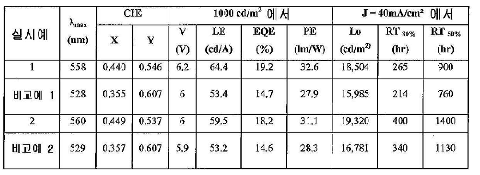
표 3의 소자예로부터, 본 발명의 화합물을 함유하는 소자는 특히 우수한 특성을 가질 수 있다는 것을 확인할 수 있다. 특히, 발광성 도판트로서 화합물 1을 함유하는 발광층을 갖는 소자가 그러하다. 이러한 소자는 화합물 1이 소자 안정성에 이로울 수 있다는 것을 증명한다. 특히, 비교예 1 및 소자예 1은 RT80%(초기 휘도 L0이 그 초기 휘도의 80%로 감소하는 데 걸리는 시간으로 정의됨)가 각각 760 시간 및 900 시간이다. 비교예 2 및 소자예 2는 RT80%가 각각 1130 시간 및 1400 시간이다. 이러한 결과는 이종리간드성 Ir(Ⅲ) 착물의 연장된 컨쥬게이팅이 소자 안정성에 이로울 수 있다는 것을 나타낸다. From the device examples of Table 3, it can be confirmed that the device containing the compound of the present invention can have particularly excellent properties. In particular, it is the element which has a light emitting layer containing compound 1 as a luminescent dopant. This device demonstrates that Compound 1 may be beneficial for device stability. In particular, Comparative Example 1 and Device Example 1 have RT 80% (defined as the time taken for the initial luminance L 0 to decrease to 80% of its initial luminance) of 760 hours and 900 hours, respectively. In Comparative Example 2 and Device Example 2, the RT 80% is 1130 hours and 1400 hours, respectively. These results indicate that extended conjugation of heteroligand Ir (III) complexes may be beneficial to device stability.
낮은 증발 온도는 OLED 제조에 바람직하다. 물질을 장기간 가열하는 것이 OLED 제조 중에 필요하여, 낮은 증발 온도를 갖는 물질은 열응력이 보다 낮아, 전형적으로 보다 깨끗한 증발을 유도한다. 화합물 1의 이종원자 고리에 페닐을 첨가하여 달성하는 연장된 컨쥬게이팅은 낮은 승화 온도를 유도한다. 따라서, 화합물 1을 갖는 소자는 향상된 제조를 보유할 수 있다.Low evaporation temperatures are desirable for OLED production. Long term heating of the material is necessary during OLED fabrication, so materials with low evaporation temperatures have lower thermal stresses, typically leading to cleaner evaporation. Prolonged conjugation achieved by the addition of phenyl to the heteroatom ring of Compound 1 leads to low sublimation temperatures. Thus, devices with compound 1 can have improved manufacturing.
표 4의 소자예 3∼12의 유기 스택은 ITO 표면으로부터 순차적으로, 정공 주입층(HIL)으로서 E1 100Å, 정공 이송층(HTL)으로서 4,4'-비스[N-(l-나프틸)-N-페닐아미노]비페닐(α-NPD) 300Å, 발광층(EML)으로서 본 발명의 화합물의 7%, 10% 또는 15%로 도핑된 H1 또는 H2 300Å, 차단층으로서 H1 또는 H2 50Å 및 ETL로서 Alq3(트리스-8-히드록시퀴놀린 알루미늄) 400Å로 구성된다. 상기 소자예의 소자 구조는 도 3에 또한 요약되어 있다.The organic stacks of the device examples 3 to 12 of Table 4 were sequentially removed from the surface of the ITO,
비교예 3은 E1이 발광성 도판트로서 사용된다는 것을 제외하고 상기 소자예와 유사하게 제조하였다.Comparative Example 3 was prepared similarly to the above device example except that E1 was used as the luminescent dopant.
상기 소자 구조 및 데이타는 표 4 및 5에 요약하였다. 표 4는 소자 구조를 나타내고, 표 5은 그 소자에 대한 상응하는 측정 결과를 나타낸다. 본 원에서 사용되는 바와 같이, E1, H1, H2 및 NPD는 하기 구조를 가진다:The device structure and data are summarized in Tables 4 and 5. Table 4 shows the device structure and Table 5 shows the corresponding measurement results for the device. As used herein, E1, H1, H2 and NPD have the following structure:

표 4Table 4

표 5Table 5
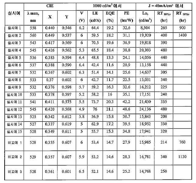
표 4의 소자예로부터, 본 발명의 화합물을 함유하는 소자는 특히 우수한 특성을 가질 수 있다는 것을 확인할 수 있다. 특히, 발광성 도판트로서 화합물 1, 화합물 2, 화합물 8∼12를 함유하는 발광층을 갖는 소자는 상기 본 발명의 화합물이 소자 안정성에 이로울 수 있다는 것을 증명한다.From the device examples of Table 4, it can be confirmed that the device containing the compound of the present invention can have particularly excellent properties. In particular, devices having light emitting layers containing Compound 1,
본 발명의 화합물, 화합물 21 내지 화합물 35이 발광 도판트이고, H-2가 호스트인 특정 소자가 제공된다. 소자예 21∼35의 유기 스택은 ITO 표면으로부터 순차적으로, 정공 주입층(HIL)으로서 E1 100Å, 정공 이송층(HTL)으로서 4,4'-비스[N-(l-나프틸)-N-페닐아미노]비페닐(α-NPD) 300Å, 발광층(EML)으로서 화합물 21∼35 및 37의 7%로 도핑된 H2 300Å, 전자 이송층(ETL2)으로서 H2 100Å 및 전자 이송층(ETL1)로서 Alq3(트리스-8-히드록시퀴놀린 알루미늄) 400Å로 구성된다.There are provided specific devices wherein compounds of the present invention, compounds 21 through 35, are luminescent dopants and H-2 is a host. The organic stacks of the device examples 21 to 35 were sequentially from the surface of the ITO,
비교 소자예 4∼6는 상기 소자예와 유사하게 제조하였으나, 소자 비교예 4에서 E2를 발광 도판트로서 사용하며; 소자 비교예 5에서는 CBP는 호스트로서 존재하고, E3를 발광 도판트로서 사용하며, HPT의 50Å를 ETL2로 사용하고, Alq3의 450Å를 ETL1으로서 사용하며; 소자 비교예 6에서는 E4를 발광 도판드로서 사용한다는 점이 다르다.Comparative Device Examples 4 to 6 were prepared similarly to the above Device Example, but in Device Comparative Example 4, E2 was used as the light emitting dopant; In device comparative example 5, CBP is present as a host, E3 is used as the light emitting dopant, 50 ms of HPT is used as ETL2, and 450 ms of Alq 3 is used as ETL1; In device comparison example 6, E4 is used as a light emitting dopant.
본 원에서 사용되는 바와 같이, 하기 화합물은 하기 구조를 가진다:As used herein, the following compounds have the following structure:
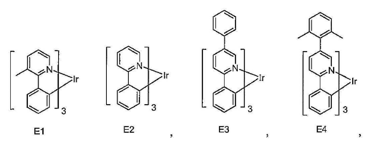
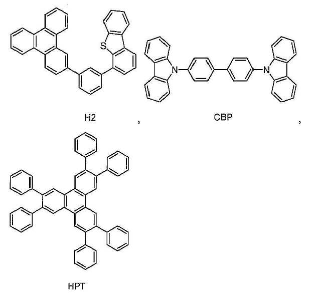
OLED에서 사용하기 위한 특정 물질이 제공된다. 상기 물질은 상기 소자의 발광층에서 발광 도판트로서 사용할 수 있다. 본 원에서 제공되는 물질을 사용하여 효율이 높고 전계발광이 좁은 소자를 제공할 수 있다. 또한, 이러한 물질은 향상된 안정성 및 향상된 가공성, 예컨대 높은 용해도 및 낮은 증발 온도를 제공할 수 있다.Certain materials are provided for use in OLEDs. The material can be used as a light emitting dopant in the light emitting layer of the device. Materials provided herein can be used to provide devices with high efficiency and narrow electroluminescence. In addition, these materials can provide improved stability and improved processability, such as high solubility and low evaporation temperatures.
표 6Table 6

표 6은 상기 소자예에 사용된 발광 화합물, 화합물 21∼33의 증발 온도를 각각 소자 비교예 4 및 5에 사용된 발광 화합물 E2 및 E3의 증발 온도와 비교한 것을 나타낸다. 특히, 화합물 21∼24는 E3보다 상당히 낮은 증발 온도를 보유한다. 보다 낮은 증발 온도는 도판트의 열증발 및 장기 열안정성에 대해서 바람직한 특성일 수 있다. 화합물 21∼23 중 C 고리 페닐-피리딘은 E3에서 나타낸 바와 같이 상기 2개의 고리 사이에서 상기 페닐-피리딘 뒤틀림(twist)보다 많은 뒤틀림을 보유한다. 상기 뒤틀린 C 고리 특징부를 함유하는 이종리간드성 화합물(화합물 25∼33 및 37)은 C 고리를 전혀 갖지 않는 E2와 유사하거나 보다 낮은 증발 온도를 보유한다. 상기 결과는 상기 뒤틀린 C 고리 특징부가 증발 온도를 낮출 수 있는 동시에, 상기 특징부가 없는 구조 유사 화합물만큼 또는 보다 높게 분자량을 유지할 수 있다는 것을 나타낸다.Table 6 shows that the evaporation temperatures of the light emitting compounds and the
표 7TABLE 7

표 7은 소자예 및 소자 비교예에 대한 추가 소자 데이타를 나타낸다. 특히, 표 7은 소자 비교예 4, 5 및 6과 비교한, 소자예 16∼18 및 27에 대한 λmax 및 CIE 좌표를 제공한다. 상기 데이타로부터, 소자예 16∼18 및 27은 소자 비교예 5로부터 유의적으로 청색 이동하였음을 확인할 수 있다. 이러한 결과는 컨쥬게이팅이 상기 뒤틀린 페닐 C 고리의 존재에 의해 감소될 수 있다는 것을 제시한다. Table 7 shows additional device data for device examples and device comparative examples. In particular, Table 7 provides λ max and CIE coordinates for Device Examples 16-18 and 27, compared to Device Comparative Examples 4, 5, and 6. From the above data, it can be seen that device examples 16 to 18 and 27 shifted significantly blue from device comparison example 5. These results suggest that conjugation can be reduced by the presence of the twisted phenyl C ring.
표 8Table 8

표 8은 소자예 16∼29와 소자 비교예 4 및 6 간의 소자 특성 비교를 제공한다. 상기 데이타로부터, 소자예 16(화합물 21), 17(화합물 22), 19(화합물 25), 20(화합물 26), 21(화합물 27), 23(화합물 29), 24(화합물 30), 25(화합물 31), 27(화합물 34), 28(화합물 25), 29(화합물 37)이 높은 효율 및 장기 소자 수명을 제공한다는 것을 확인할 수 있다. 특히, 발광 도판드로서 화합물 21, 22, 25, 29, 30, 31 및 34를 각각 사용하는 소자예 16, 17, 19, 23, 24, 25 및 27은 매우 우수한 소자 성능을 보유한다. 소자 비교예 4의 RT80% 196 시간과 비교하여 이러한 특정 소자는 210, 260, 245 237, 223, 254 및 290 시간의 RT80%(초기 휘도 L0가 일정 DC 드라이브 하의 실온에서 100%로부터 80%로 감소하는 데 필요한 시간으로서 정의됨)를 나타낸다. 더욱이, 소자예 16, 17, 19, 23, 24, 25 및 27 모두는 소자 비교예 4보다 높은 L0에서 작동한다. 상기 결과는 상기 페닐 C 고리가 일부 컨쥬게이팅을 발광 도판트에 부가함으로써 소자 안정성을 향상시킬 수 있다는 것을 나타낸다. 그러나, E-3에서와 같은 규칙적인 컨쥬게이팅에서의 페닐에 비해 발광에서 유의적인 적색 이동을 유발시키지 않는, 전술한 바와 같은 상기 뒤틀린 특징부의 존재에 의해 상기 컨쥬게이팅은 한정된다. 또한, 소자예 16∼20, 23∼25 및 27∼29의 EL 스펙트럼은 모두 비교예 4보다 좁다. 좁은 발광은 OLED 기술에서의 포화된 색좌표, 높은 LE:EQE 전환율, 마이크로캐비티 터닝(microcavity tuning) 및 색필터 매칭을 달성하기 위한 바람직한 인자일 수 있다.Table 8 provides a comparison of device characteristics between Device Examples 16-29 and Device Comparative Examples 4 and 6. From the above data, Device Examples 16 (Compound 21), 17 (Compound 22), 19 (Compound 25), 20 (Compound 26), 21 (Compound 27), 23 (Compound 29), 24 (Compound 30), 25 ( It can be seen that Compounds 31), 27 (Compound 34), 28 (Compound 25) and 29 (Compound 37) provide high efficiency and long term device life. In particular, device examples 16, 17, 19, 23, 24, 25, and 27, which use compounds 21, 22, 25, 29, 30, 31, and 34 as light emitting dopants, respectively, have very good device performance. This particular device as compared to 196 hours RT 80% of the element of Comparative Example 4 is 210, 260, 245 237, 223, 254 and 290 hours of RT 80% (the initial luminance L 0 80 from 100% at the room temperature constant under DC drive Defined as time required to decrease to%). Moreover, device examples 16, 17, 19, 23, 24, 25, and 27 all operate at L 0 higher than device comparative example 4. The results indicate that the phenyl C ring can improve device stability by adding some conjugation to the luminescent dopant. However, the conjugation is limited by the presence of the warped feature as described above, which does not cause significant red shift in luminescence compared to phenyl in regular conjugation as in E-3. In addition, the EL spectra of Device Examples 16 to 20, 23 to 25, and 27 to 29 were all narrower than Comparative Example 4. Narrow light emission may be a desirable factor for achieving saturated color coordinates, high LE: EQE conversion, microcavity tuning and color filter matching in OLED technology.
본원에서 기술된 다양한 실시양태는 단지 예로서 존재하며, 본 발명의 범위를 한정하려는 의도는 아니라는 것이 이해된다. 예를 들어, 본 원에서 기술된 많은 물질 및 구조는 본 발명의 사상을 벗어남 없이 다른 물질 및 구조로 대체할 수 있다. 따라서, 청구되는 본 발명은, 당업자에게 명백하게 되는 바와 같이, 본 원에서 기술된 특정 실시예 및 바람직한 실시예로부터의 변경예를 포함할 수 있다. 본 발명의 작용 원리에 대한 다양한 이론은 한정되지 않는다는 것이 이해되게 된다.It is understood that the various embodiments described herein are by way of example only and are not intended to limit the scope of the invention. For example, many of the materials and structures described herein may be replaced with other materials and structures without departing from the spirit of the invention. Thus, the claimed invention may include variations from the specific and preferred embodiments described herein, as will be apparent to one of ordinary skill in the art. It is to be understood that various theories as to the principles of operation of the invention are not limited.
Claims (10)


S는 중성 리간드이고;
X는 카운터 이온이며;
A 및 B는 각각 독립적으로 5원 또는 6원 방향족 또는 헤테로방향족 고리이고, A-B는 고리 A 상의 질소 원자 및 고리 B 상의 sp2 혼성화 탄소 원자를 통해 이리듐에 배위 결합된 방향족 또는 헤테로방향족 고리의 결합쌍을 나타내며;
C 및 D는 각각 독립적으로 5원 또는 6원 방향족 또는 헤테로방향족 고리이고, C-D는 고리 C 상의 질소 고리 원자 및 고리 D 상의 sp2 혼성화 탄소 원자를 통해 이리듐에 배위 결합된 방향족 또는 헤테로방향족 고리의 결합쌍을 나타내며;
RA, RB, RC 및 RD는 각각 독립적으로 비치환, 알킬, 헤테로알킬, 아릴 또는 헤테로아릴 기로 구성된 군으로부터 선택되고;
RA, RB, RC 및 RD 각각은 1 이상의 치환기를 나타내며;
R은 알킬, 헤테로알킬 또는 퍼플루오로알킬 기이고, 상기 2개의 R은 임의로 결합하여 고리를 형성하는 것인 방법.
S is a neutral ligand;
X is a counter ion;
A and B are each independently a 5- or 6-membered aromatic or heteroaromatic ring, AB is a bonding pair of an aromatic or heteroaromatic ring coordinated to iridium via a nitrogen atom on ring A and an sp 2 hybridized carbon atom on ring B Represents;
C and D are each independently a 5- or 6-membered aromatic or heteroaromatic ring, and CD is a bond of an aromatic or heteroaromatic ring coordinated to iridium via a nitrogen ring atom on ring C and an sp 2 hybridized carbon atom on ring D A pair;
R A , R B , R C and R D are each independently selected from the group consisting of unsubstituted, alkyl, heteroalkyl, aryl or heteroaryl groups;
Each of R A , R B , R C and R D represents one or more substituents;
R is an alkyl, heteroalkyl or perfluoroalkyl group, wherein the two R's are optionally bonded to form a ring.


R은 아릴 또는 헤테로아릴이고,
X는 I, Br, Cl 및 OTf로 구성된 군으로부터 선택되는 것인 방법.The method of claim 1,
R is aryl or heteroaryl,
X is selected from the group consisting of I, Br, Cl and OTf.


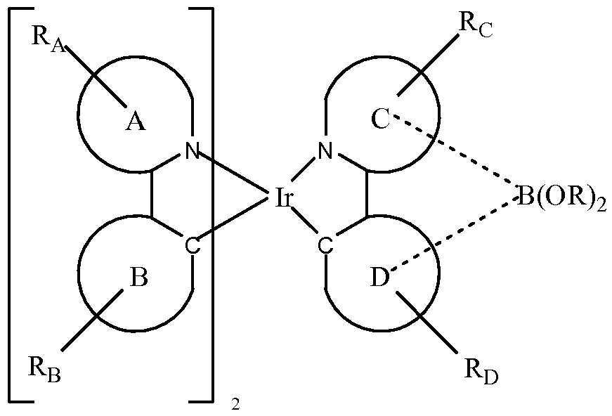


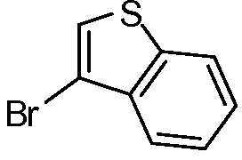

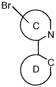


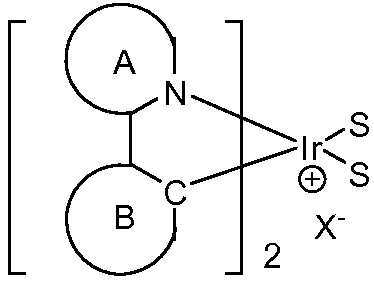
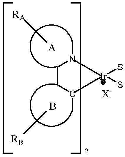


Applications Claiming Priority (9)
| Application Number | Priority Date | Filing Date | Title |
|---|---|---|---|
| US9396708P | 2008-09-03 | 2008-09-03 | |
| US61/093,967 | 2008-09-03 | ||
| US14045908P | 2008-12-23 | 2008-12-23 | |
| US61/140,459 | 2008-12-23 | ||
| US22908809P | 2009-07-28 | 2009-07-28 | |
| US61/229,088 | 2009-07-28 | ||
| USPCT/US2009/052045 | 2009-07-29 | ||
| PCT/US2009/052045 WO2010027583A1 (en) | 2008-09-03 | 2009-07-29 | Phosphorescent materials |
| PCT/US2009/055890 WO2010028151A1 (en) | 2008-09-03 | 2009-09-03 | Phosphorescent materials |
Related Parent Applications (1)
| Application Number | Title | Priority Date | Filing Date |
|---|---|---|---|
| KR1020197004183A Division KR102082091B1 (en) | 2008-09-03 | 2009-09-03 | Phosphorescent materials |
Related Child Applications (1)
| Application Number | Title | Priority Date | Filing Date |
|---|---|---|---|
| KR1020217001710A Division KR20210010949A (en) | 2008-09-03 | 2009-09-03 | Phosphorescent materials |
Publications (2)
| Publication Number | Publication Date |
|---|---|
| KR20200021549A true KR20200021549A (en) | 2020-02-28 |
| KR102207559B1 KR102207559B1 (en) | 2021-01-26 |
Family
ID=41010418
Family Applications (10)
| Application Number | Title | Priority Date | Filing Date |
|---|---|---|---|
| KR1020217041284A KR102530743B1 (en) | 2008-09-03 | 2009-09-03 | Phosphorescent materials |
| KR1020187011992A KR101969690B1 (en) | 2008-09-03 | 2009-09-03 | Phosphorescent materials |
| KR1020197004183A KR102082091B1 (en) | 2008-09-03 | 2009-09-03 | Phosphorescent materials |
| KR1020237015100A KR20230066485A (en) | 2008-09-03 | 2009-09-03 | Phosphorescent materials |
| KR1020207004780A KR102207559B1 (en) | 2008-09-03 | 2009-09-03 | Phosphorescent materials |
| KR1020217001710A KR20210010949A (en) | 2008-09-03 | 2009-09-03 | Phosphorescent materials |
| KR1020117007709A KR20110065496A (en) | 2008-09-03 | 2009-09-03 | Phosphorescent materials |
| KR1020157033289A KR101691609B1 (en) | 2008-09-03 | 2009-09-03 | Phosphorescent materials |
| KR1020187004819A KR101950655B1 (en) | 2008-09-03 | 2009-09-03 | Phosphorescent materials |
| KR1020167036340A KR101831916B1 (en) | 2008-09-03 | 2009-09-03 | Phosphorescent materials |
Family Applications Before (4)
| Application Number | Title | Priority Date | Filing Date |
|---|---|---|---|
| KR1020217041284A KR102530743B1 (en) | 2008-09-03 | 2009-09-03 | Phosphorescent materials |
| KR1020187011992A KR101969690B1 (en) | 2008-09-03 | 2009-09-03 | Phosphorescent materials |
| KR1020197004183A KR102082091B1 (en) | 2008-09-03 | 2009-09-03 | Phosphorescent materials |
| KR1020237015100A KR20230066485A (en) | 2008-09-03 | 2009-09-03 | Phosphorescent materials |
Family Applications After (5)
| Application Number | Title | Priority Date | Filing Date |
|---|---|---|---|
| KR1020217001710A KR20210010949A (en) | 2008-09-03 | 2009-09-03 | Phosphorescent materials |
| KR1020117007709A KR20110065496A (en) | 2008-09-03 | 2009-09-03 | Phosphorescent materials |
| KR1020157033289A KR101691609B1 (en) | 2008-09-03 | 2009-09-03 | Phosphorescent materials |
| KR1020187004819A KR101950655B1 (en) | 2008-09-03 | 2009-09-03 | Phosphorescent materials |
| KR1020167036340A KR101831916B1 (en) | 2008-09-03 | 2009-09-03 | Phosphorescent materials |
Country Status (7)
| Country | Link |
|---|---|
| US (8) | US8519384B2 (en) |
| EP (3) | EP4223854A3 (en) |
| JP (7) | JP5826630B2 (en) |
| KR (10) | KR102530743B1 (en) |
| CN (2) | CN103864675B (en) |
| TW (7) | TWI734557B (en) |
| WO (2) | WO2010027583A1 (en) |
Cited By (1)
| Publication number | Priority date | Publication date | Assignee | Title |
|---|---|---|---|---|
| WO2021167389A1 (en) | 2020-02-21 | 2021-08-26 | 한국과학기술원 | Pharmaceutical composition for preventing or treating cancer, containing mtor-signaling inhibitor as active ingredient |
Families Citing this family (181)
| Publication number | Priority date | Publication date | Assignee | Title |
|---|---|---|---|---|
| KR100560790B1 (en) * | 2003-11-25 | 2006-03-13 | 삼성에스디아이 주식회사 | Electroluminescent display device having a good performance at high temperature |
| KR102103062B1 (en) | 2006-02-10 | 2020-04-22 | 유니버셜 디스플레이 코포레이션 | METAL COMPLEXES OF CYCLOMETALLATED IMIDAZO[1,2-f]PHENANTHRIDINE AND DIIMIDAZO[1,2-A:1',2'-C]QUINAZOLINE LIGANDS AND ISOELECTRONIC AND BENZANNULATED ANALOGS THEREOF |
| WO2010027583A1 (en) * | 2008-09-03 | 2010-03-11 | Universal Display Corporation | Phosphorescent materials |
| JP5047314B2 (en) * | 2010-01-15 | 2012-10-10 | 富士フイルム株式会社 | Organic electroluminescence device |
| US8288187B2 (en) | 2010-01-20 | 2012-10-16 | Universal Display Corporation | Electroluminescent devices for lighting applications |
| US9175211B2 (en) | 2010-03-03 | 2015-11-03 | Universal Display Corporation | Phosphorescent materials |
| CN103140564B (en) * | 2010-07-30 | 2015-11-25 | 罗门哈斯电子材料韩国有限公司 | Use electroluminescent compounds as the electroluminescent device of luminescent material |
| KR101745336B1 (en) * | 2010-07-30 | 2017-06-14 | 롬엔드하스전자재료코리아유한회사 | Electroluminescent device using the electroluminescent compounds |
| KR20140009263A (en) * | 2011-02-11 | 2014-01-22 | 유니버셜 디스플레이 코포레이션 | Organic light emitting device and materials for use in same |
| JP5964328B2 (en) * | 2011-02-11 | 2016-08-03 | ユニバーサル ディスプレイ コーポレイション | ORGANIC LIGHT EMITTING DEVICE AND MATERIAL FOR USE IN THE ORGANIC LIGHT EMITTING DEVICE |
| US10079349B2 (en) * | 2011-05-27 | 2018-09-18 | Universal Display Corporation | Organic electroluminescent materials and devices |
| US10158089B2 (en) | 2011-05-27 | 2018-12-18 | Universal Display Corporation | Organic electroluminescent materials and devices |
| US9783564B2 (en) * | 2011-07-25 | 2017-10-10 | Universal Display Corporation | Organic electroluminescent materials and devices |
| WO2013022419A1 (en) * | 2011-08-05 | 2013-02-14 | Universal Display Corporation | Phosphorescent organic light emitting devices combined with hole transport material having high operating stability |
| KR101976104B1 (en) * | 2011-11-01 | 2019-05-09 | 유니버셜 디스플레이 코포레이션 | Reducing oled device efficiency at low luminance |
| JP2013103918A (en) | 2011-11-15 | 2013-05-30 | Udc Ireland Ltd | Charge-transporting material, organic electroluminescent element, and light-emitting device, display device and illumination device characterized by using the element |
| EP2676964A1 (en) | 2012-06-18 | 2013-12-25 | Solvay Sa | Preparation of heteroleptic metal complexes |
| KR20140117432A (en) | 2011-12-28 | 2014-10-07 | 솔베이(소시에떼아노님) | Preparation of heteroleptic metal complexes |
| KR102012047B1 (en) | 2012-01-06 | 2019-08-19 | 유니버셜 디스플레이 코포레이션 | Highly efficient phosphorescent materials |
| US9985232B2 (en) | 2012-05-17 | 2018-05-29 | Idemitsu Kosan Co., Ltd. | Biscarbazole derivative host materials for OLED emissive region |
| WO2013187896A1 (en) * | 2012-06-14 | 2013-12-19 | Universal Display Corporation | Biscarbazole derivative host materials and green emitter for oled emissive region |
| CN104364344A (en) * | 2012-06-14 | 2015-02-18 | 通用显示公司 | Biscarbazole derivative host materials and red emitters for OLED emissive regions |
| CN103483387A (en) * | 2012-06-15 | 2014-01-01 | 李晓常 | Stable easy-preparation organic photoelectric material and its application |
| KR101344787B1 (en) | 2012-07-04 | 2013-12-26 | 제일모직주식회사 | Compound for organic optoelectronic device, organic light emitting diode including the same and display including the organic light emitting diode |
| JP2015524610A (en) | 2012-07-04 | 2015-08-24 | サムスン エスディアイ カンパニー,リミテッド | Composition for organic light emitting device, organic light emitting layer containing the same, and organic light emitting device |
| US9725476B2 (en) * | 2012-07-09 | 2017-08-08 | Universal Display Corporation | Silylated metal complexes |
| US9231218B2 (en) | 2012-07-10 | 2016-01-05 | Universal Display Corporation | Phosphorescent emitters containing dibenzo[1,4]azaborinine structure |
| US9540329B2 (en) | 2012-07-19 | 2017-01-10 | Universal Display Corporation | Organic electroluminescent materials and devices |
| KR102102580B1 (en) * | 2012-07-20 | 2020-04-22 | 롬엔드하스전자재료코리아유한회사 | Organic Electroluminescence Device |
| US11917901B2 (en) | 2012-08-07 | 2024-02-27 | Udc Ireland Limited | Metal complexes |
| CN113943306A (en) | 2012-09-20 | 2022-01-18 | Udc 爱尔兰有限责任公司 | Azadibenzofurans for electronic applications and electronic devices comprising same |
| US9252363B2 (en) | 2012-10-04 | 2016-02-02 | Universal Display Corporation | Aryloxyalkylcarboxylate solvent compositions for inkjet printing of organic layers |
| US9634264B2 (en) | 2012-11-09 | 2017-04-25 | Universal Display Corporation | Organic electroluminescent materials and devices |
| US9748500B2 (en) | 2015-01-15 | 2017-08-29 | Universal Display Corporation | Organic light emitting materials |
| US9685617B2 (en) | 2012-11-09 | 2017-06-20 | Universal Display Corporation | Organic electronuminescent materials and devices |
| US8946697B1 (en) * | 2012-11-09 | 2015-02-03 | Universal Display Corporation | Iridium complexes with aza-benzo fused ligands |
| US9196860B2 (en) | 2012-12-04 | 2015-11-24 | Universal Display Corporation | Compounds for triplet-triplet annihilation upconversion |
| US8716484B1 (en) | 2012-12-05 | 2014-05-06 | Universal Display Corporation | Hole transporting materials with twisted aryl groups |
| US9653691B2 (en) | 2012-12-12 | 2017-05-16 | Universal Display Corporation | Phosphorescence-sensitizing fluorescence material system |
| JP5911418B2 (en) | 2012-12-27 | 2016-04-27 | キヤノン株式会社 | Organic light emitting device |
| JP5911419B2 (en) | 2012-12-27 | 2016-04-27 | キヤノン株式会社 | Organic light emitting device and display device |
| JP5818870B2 (en) | 2012-12-27 | 2015-11-18 | キヤノン株式会社 | Organic light emitting device and display device |
| JP6071569B2 (en) | 2013-01-17 | 2017-02-01 | キヤノン株式会社 | Organic light emitting device |
| JP5984689B2 (en) * | 2013-01-21 | 2016-09-06 | キヤノン株式会社 | Organometallic complex and organic light emitting device using the same |
| JP6222931B2 (en) | 2013-01-21 | 2017-11-01 | キヤノン株式会社 | Organic light emitting device |
| US10400163B2 (en) * | 2013-02-08 | 2019-09-03 | Universal Display Corporation | Organic electroluminescent materials and devices |
| EP3301099B1 (en) * | 2013-02-21 | 2021-04-28 | Universal Display Corporation | Phosphorescent homoleptic tris-[deuterated-2-(2-pyridinyl)phenyl]-iridium complexes for use in light-emitting devices |
| US10367154B2 (en) * | 2013-02-21 | 2019-07-30 | Universal Display Corporation | Organic electroluminescent materials and devices |
| WO2014204464A1 (en) * | 2013-06-20 | 2014-12-24 | Universal Display Corporation | Phosphorescent organic light emitting devices having a hole-transporting host in the emissive region |
| JP6341772B2 (en) * | 2013-06-28 | 2018-06-13 | 株式会社半導体エネルギー研究所 | Organometallic complex, light-emitting element, light-emitting device, electronic device, and lighting device |
| KR102103959B1 (en) * | 2013-07-11 | 2020-04-28 | 삼성디스플레이 주식회사 | Iridium complex and Organic light emitting device comprising the same |
| US10074806B2 (en) * | 2013-08-20 | 2018-09-11 | Universal Display Corporation | Organic electroluminescent materials and devices |
| KR20150022529A (en) * | 2013-08-23 | 2015-03-04 | 삼성디스플레이 주식회사 | Organic light emitting device |
| KR102180085B1 (en) * | 2013-09-12 | 2020-11-17 | 덕산네오룩스 주식회사 | Organic electronic element using a compound for organic electronic element, and an electronic device thereof |
| KR20160055802A (en) | 2013-09-12 | 2016-05-18 | 가부시키가이샤 한도오따이 에네루기 켄큐쇼 | Organometallic iridium complex, light-emitting element, light-emitting device, electronic device, and lighting device |
| EP3063153B1 (en) | 2013-10-31 | 2018-03-07 | Idemitsu Kosan Co., Ltd. | Azadibenzothiophenes for electronic applications |
| US9876173B2 (en) | 2013-12-09 | 2018-01-23 | Universal Display Corporation | Organic electroluminescent materials and devices |
| US10355227B2 (en) * | 2013-12-16 | 2019-07-16 | Universal Display Corporation | Metal complex for phosphorescent OLED |
| WO2015134017A1 (en) * | 2014-03-05 | 2015-09-11 | Universal Display Corporation | Phosphorescent oled devices |
| US9450198B2 (en) | 2014-04-15 | 2016-09-20 | Universal Display Corporation | Organic electroluminescent materials and devices |
| KR102208247B1 (en) * | 2014-05-29 | 2021-01-27 | 덕산네오룩스 주식회사 | Organic electronic element using a compound for organic electronic element, and an electronic device thereof |
| US10297762B2 (en) | 2014-07-09 | 2019-05-21 | Universal Display Corporation | Organic electroluminescent materials and devices |
| EP3174885B1 (en) | 2014-07-28 | 2019-10-02 | Idemitsu Kosan Co., Ltd. | 2,9-functionalized benzimidazolo[1,2-a]benzimidazoles as hosts for organic light emitting diodes (oleds) |
| EP2982676B1 (en) | 2014-08-07 | 2018-04-11 | Idemitsu Kosan Co., Ltd. | Benzimidazo[2,1-B]benzoxazoles for electronic applications |
| TWI663173B (en) | 2014-08-08 | 2019-06-21 | 愛爾蘭商Udc愛爾蘭責任有限公司 | Electroluminescent imidazo-quinoxaline carbene metal complexes |
| EP2993215B1 (en) | 2014-09-04 | 2019-06-19 | Idemitsu Kosan Co., Ltd. | Azabenzimidazo[2,1-a]benzimidazoles for electronic applications |
| US10749113B2 (en) * | 2014-09-29 | 2020-08-18 | Universal Display Corporation | Organic electroluminescent materials and devices |
| US10361375B2 (en) | 2014-10-06 | 2019-07-23 | Universal Display Corporation | Organic electroluminescent materials and devices |
| EP3015469B1 (en) | 2014-10-30 | 2018-12-19 | Idemitsu Kosan Co., Ltd. | 5-(benzimidazol-2-yl)benzimidazo[1,2-a]benzimidazoles for electronic applications |
| WO2016079667A1 (en) | 2014-11-17 | 2016-05-26 | Idemitsu Kosan Co., Ltd. | Indole derivatives for electronic applications |
| WO2016079169A1 (en) | 2014-11-18 | 2016-05-26 | Basf Se | Pt- or pd-carbene complexes for use in organic light emitting diodes |
| TWI526448B (en) | 2014-12-03 | 2016-03-21 | 財團法人工業技術研究院 | Organic metal compound, and organic light-emitting device employing the same |
| TWI586672B (en) | 2014-12-03 | 2017-06-11 | 財團法人工業技術研究院 | Organic metal compounds and organic electroluminescence devices employing the same |
| EP3034506A1 (en) | 2014-12-15 | 2016-06-22 | Idemitsu Kosan Co., Ltd | 4-functionalized carbazole derivatives for electronic applications |
| EP3034507A1 (en) | 2014-12-15 | 2016-06-22 | Idemitsu Kosan Co., Ltd | 1-functionalized dibenzofurans and dibenzothiophenes for organic light emitting diodes (OLEDs) |
| KR102343146B1 (en) * | 2014-12-16 | 2021-12-27 | 삼성디스플레이 주식회사 | Organometallic compound and organic light emitting device comprising the same |
| KR102344883B1 (en) * | 2014-12-17 | 2021-12-29 | 삼성전자주식회사 | Organometallic compound and organic light emitting device including the same |
| JP6772188B2 (en) | 2015-02-03 | 2020-10-21 | メルク、パテント、ゲゼルシャフト、ミット、ベシュレンクテル、ハフツングMerck Patent GmbH | Metal complex |
| EP3053918B1 (en) | 2015-02-06 | 2018-04-11 | Idemitsu Kosan Co., Ltd. | 2-carbazole substituted benzimidazoles for electronic applications |
| EP3054498B1 (en) | 2015-02-06 | 2017-09-20 | Idemitsu Kosan Co., Ltd. | Bisimidazodiazocines |
| US9929361B2 (en) | 2015-02-16 | 2018-03-27 | Universal Display Corporation | Organic electroluminescent materials and devices |
| GB201511300D0 (en) * | 2015-06-26 | 2015-08-12 | Cambridge Display Tech Ltd | Metal complex and organic light-emitting device |
| EP3061759B1 (en) | 2015-02-24 | 2019-12-25 | Idemitsu Kosan Co., Ltd | Nitrile substituted dibenzofurans |
| US11056657B2 (en) | 2015-02-27 | 2021-07-06 | University Display Corporation | Organic electroluminescent materials and devices |
| US10400001B2 (en) | 2015-03-10 | 2019-09-03 | National Institute Of Advanced Industrial Science And Technology | Heteroleptic iridium complex, and light-emitting material and organic light-emitting element using compound |
| EP3070144B1 (en) | 2015-03-17 | 2018-02-28 | Idemitsu Kosan Co., Ltd. | Seven-membered ring compounds |
| EP3072943B1 (en) | 2015-03-26 | 2018-05-02 | Idemitsu Kosan Co., Ltd. | Dibenzofuran/carbazole-substituted benzonitriles |
| EP3075737B1 (en) | 2015-03-31 | 2019-12-04 | Idemitsu Kosan Co., Ltd | Benzimidazolo[1,2-a]benzimidazole carrying aryl- or heteroarylnitril groups for organic light emitting diodes |
| US9478758B1 (en) * | 2015-05-08 | 2016-10-25 | Universal Display Corporation | Organic electroluminescent materials and devices |
| US9859510B2 (en) | 2015-05-15 | 2018-01-02 | Universal Display Corporation | Organic electroluminescent materials and devices |
| US10418568B2 (en) | 2015-06-01 | 2019-09-17 | Universal Display Corporation | Organic electroluminescent materials and devices |
| US11127905B2 (en) | 2015-07-29 | 2021-09-21 | Universal Display Corporation | Organic electroluminescent materials and devices |
| US11522140B2 (en) | 2015-08-17 | 2022-12-06 | Universal Display Corporation | Organic electroluminescent materials and devices |
| US10672996B2 (en) * | 2015-09-03 | 2020-06-02 | Universal Display Corporation | Organic electroluminescent materials and devices |
| US20170092880A1 (en) | 2015-09-25 | 2017-03-30 | Universal Display Corporation | Organic electroluminescent materials and devices |
| WO2017056055A1 (en) | 2015-10-01 | 2017-04-06 | Idemitsu Kosan Co., Ltd. | Benzimidazolo[1,2-a]benzimidazole carrying triazine groups for organic light emitting diodes |
| EP3150606B1 (en) | 2015-10-01 | 2019-08-14 | Idemitsu Kosan Co., Ltd. | Benzimidazolo[1,2-a]benzimidazoles carrying benzofurane or benzothiophene groups for organic light emitting diodes |
| US20180291028A1 (en) | 2015-10-01 | 2018-10-11 | Idemitsu Kosan Co., Ltd. | Benzimidazolo[1,2-a]benzimidazole carrying benzimidazolo[1,2-a]benzimidazolyl groups, carbazolyl groups, benzofurane groups or benzothiophene groups for organic light emitting diodes |
| EP3150604B1 (en) | 2015-10-01 | 2021-07-14 | Idemitsu Kosan Co., Ltd. | Benzimidazolo[1,2-a]benzimidazole carrying benzimidazolo[1,2-a]benzimidazolylyl groups, carbazolyl groups, benzofurane groups or benzothiophene groups for organic light emitting diodes |
| WO2017078182A1 (en) | 2015-11-04 | 2017-05-11 | Idemitsu Kosan Co., Ltd. | Benzimidazole fused heteroaryls |
| WO2017093958A1 (en) | 2015-12-04 | 2017-06-08 | Idemitsu Kosan Co., Ltd. | Benzimidazolo[1,2-a]benzimidazole derivatives for organic light emitting diodes |
| CN105481903B (en) * | 2015-12-09 | 2018-08-17 | 江苏三月光电科技有限公司 | A kind of phosphorescent iridium complex of the pyridazine of phenyl containing 3- structure and its application |
| CN105461756B (en) * | 2015-12-09 | 2018-08-14 | 江苏三月光电科技有限公司 | A kind of phosphorescent iridium complex as OLED dopant materials |
| KR20170074170A (en) | 2015-12-21 | 2017-06-29 | 유디씨 아일랜드 리미티드 | Transition metal complexes with tripodal ligands and the use thereof in oleds |
| US20170229663A1 (en) | 2016-02-09 | 2017-08-10 | Universal Display Corporation | Organic electroluminescent materials and devices |
| JP6861551B2 (en) * | 2016-04-01 | 2021-04-21 | 株式会社半導体エネルギー研究所 | Organometallic complexes, light emitting elements, light emitting devices, electronic devices, and lighting devices |
| US10236456B2 (en) | 2016-04-11 | 2019-03-19 | Universal Display Corporation | Organic electroluminescent materials and devices |
| US10968229B2 (en) | 2016-04-12 | 2021-04-06 | Idemitsu Kosan Co., Ltd. | Seven-membered ring compounds |
| US11228003B2 (en) * | 2016-04-22 | 2022-01-18 | Universal Display Corporation | Organic electroluminescent materials and devices |
| US11228002B2 (en) * | 2016-04-22 | 2022-01-18 | Universal Display Corporation | Organic electroluminescent materials and devices |
| US11482683B2 (en) * | 2016-06-20 | 2022-10-25 | Universal Display Corporation | Organic electroluminescent materials and devices |
| US10672997B2 (en) | 2016-06-20 | 2020-06-02 | Universal Display Corporation | Organic electroluminescent materials and devices |
| US10862054B2 (en) | 2016-06-20 | 2020-12-08 | Universal Display Corporation | Organic electroluminescent materials and devices |
| US10608186B2 (en) | 2016-09-14 | 2020-03-31 | Universal Display Corporation | Organic electroluminescent materials and devices |
| US10680187B2 (en) | 2016-09-23 | 2020-06-09 | Universal Display Corporation | Organic electroluminescent materials and devices |
| US11127906B2 (en) | 2016-10-03 | 2021-09-21 | Universal Display Corporation | Organic electroluminescent materials and devices |
| US11189804B2 (en) | 2016-10-03 | 2021-11-30 | Universal Display Corporation | Organic electroluminescent materials and devices |
| US11196010B2 (en) * | 2016-10-03 | 2021-12-07 | Universal Display Corporation | Organic electroluminescent materials and devices |
| US11183642B2 (en) | 2016-10-03 | 2021-11-23 | Universal Display Corporation | Organic electroluminescent materials and devices |
| US11011709B2 (en) | 2016-10-07 | 2021-05-18 | Universal Display Corporation | Organic electroluminescent materials and devices |
| US20180130956A1 (en) | 2016-11-09 | 2018-05-10 | Universal Display Corporation | Organic electroluminescent materials and devices |
| US10680188B2 (en) | 2016-11-11 | 2020-06-09 | Universal Display Corporation | Organic electroluminescent materials and devices |
| US20180179237A1 (en) * | 2016-12-23 | 2018-06-28 | Universal Display Corporation | Organic electroluminescent materials and devices |
| US11780865B2 (en) * | 2017-01-09 | 2023-10-10 | Universal Display Corporation | Organic electroluminescent materials and devices |
| US11201298B2 (en) * | 2017-01-09 | 2021-12-14 | Universal Display Corporation | Organic electroluminescent materials and devices |
| US10686146B2 (en) | 2017-02-13 | 2020-06-16 | Feng-wen Yen | Paracyclophane-based iridium complexes for organic electroluminescence device |
| US10844085B2 (en) | 2017-03-29 | 2020-11-24 | Universal Display Corporation | Organic electroluminescent materials and devices |
| US10944060B2 (en) | 2017-05-11 | 2021-03-09 | Universal Display Corporation | Organic electroluminescent materials and devices |
| US20180370999A1 (en) | 2017-06-23 | 2018-12-27 | Universal Display Corporation | Organic electroluminescent materials and devices |
| US11228010B2 (en) | 2017-07-26 | 2022-01-18 | Universal Display Corporation | Organic electroluminescent materials and devices |
| US11744142B2 (en) | 2017-08-10 | 2023-08-29 | Universal Display Corporation | Organic electroluminescent materials and devices |
| US20190161504A1 (en) | 2017-11-28 | 2019-05-30 | University Of Southern California | Carbene compounds and organic electroluminescent devices |
| EP3492480B1 (en) | 2017-11-29 | 2021-10-20 | Universal Display Corporation | Organic electroluminescent materials and devices |
| US11937503B2 (en) | 2017-11-30 | 2024-03-19 | Universal Display Corporation | Organic electroluminescent materials and devices |
| KR102508498B1 (en) | 2018-01-02 | 2023-03-10 | 삼성디스플레이 주식회사 | Organic light-emitting device |
| US11542289B2 (en) | 2018-01-26 | 2023-01-03 | Universal Display Corporation | Organic electroluminescent materials and devices |
| CA3093445A1 (en) | 2018-03-08 | 2019-11-28 | Incyte Corporation | Aminopyrazine diol compounds as pi3k-.gamma. inhibitors |
| EP3569605A1 (en) | 2018-05-18 | 2019-11-20 | Idemitsu Kosan Co., Ltd. | Novel electroluminescent metal complexes and an organic electroluminescence device comprising the same |
| US11046658B2 (en) | 2018-07-02 | 2021-06-29 | Incyte Corporation | Aminopyrazine derivatives as PI3K-γ inhibitors |
| US20200075870A1 (en) | 2018-08-22 | 2020-03-05 | Universal Display Corporation | Organic electroluminescent materials and devices |
| CN110872325B (en) * | 2018-09-03 | 2021-05-21 | 广东阿格蕾雅光电材料有限公司 | Organic luminescent material based on platinum tetradentate ONCN complex, preparation method and application thereof in organic light-emitting diode |
| US11737349B2 (en) | 2018-12-12 | 2023-08-22 | Universal Display Corporation | Organic electroluminescent materials and devices |
| US11780829B2 (en) | 2019-01-30 | 2023-10-10 | The University Of Southern California | Organic electroluminescent materials and devices |
| US20200251664A1 (en) | 2019-02-01 | 2020-08-06 | Universal Display Corporation | Organic electroluminescent materials and devices |
| TW202043247A (en) | 2019-02-11 | 2020-12-01 | 德商麥克專利有限公司 | Metal complexes |
| JP2020158491A (en) | 2019-03-26 | 2020-10-01 | ユニバーサル ディスプレイ コーポレイション | Organic electroluminescent materials and devices |
| US11827651B2 (en) | 2019-05-13 | 2023-11-28 | Universal Display Corporation | Organic electroluminescent materials and devices |
| US20210032278A1 (en) | 2019-07-30 | 2021-02-04 | Universal Display Corporation | Organic electroluminescent materials and devices |
| US20210047354A1 (en) | 2019-08-16 | 2021-02-18 | Universal Display Corporation | Organic electroluminescent materials and devices |
| US20210135130A1 (en) | 2019-11-04 | 2021-05-06 | Universal Display Corporation | Organic electroluminescent materials and devices |
| US20210217969A1 (en) | 2020-01-06 | 2021-07-15 | Universal Display Corporation | Organic electroluminescent materials and devices |
| US20220336759A1 (en) | 2020-01-28 | 2022-10-20 | Universal Display Corporation | Organic electroluminescent materials and devices |
| US11296292B2 (en) | 2020-04-15 | 2022-04-05 | Cynora Gmbh | Organic electroluminescent device emitting green light |
| EP3937268A1 (en) | 2020-07-10 | 2022-01-12 | Universal Display Corporation | Plasmonic oleds and vertical dipole emitters |
| JP2023541976A (en) | 2020-09-18 | 2023-10-04 | 三星ディスプレイ株式會社 | organic electroluminescent device |
| US20220158096A1 (en) | 2020-11-16 | 2022-05-19 | Universal Display Corporation | Organic electroluminescent materials and devices |
| US20220162243A1 (en) | 2020-11-24 | 2022-05-26 | Universal Display Corporation | Organic electroluminescent materials and devices |
| US20220165967A1 (en) | 2020-11-24 | 2022-05-26 | Universal Display Corporation | Organic electroluminescent materials and devices |
| US20220271241A1 (en) | 2021-02-03 | 2022-08-25 | Universal Display Corporation | Organic electroluminescent materials and devices |
| EP4060758A3 (en) | 2021-02-26 | 2023-03-29 | Universal Display Corporation | Organic electroluminescent materials and devices |
| EP4059915A3 (en) | 2021-02-26 | 2022-12-28 | Universal Display Corporation | Organic electroluminescent materials and devices |
| US20220298192A1 (en) | 2021-03-05 | 2022-09-22 | Universal Display Corporation | Organic electroluminescent materials and devices |
| US20220298190A1 (en) | 2021-03-12 | 2022-09-22 | Universal Display Corporation | Organic electroluminescent materials and devices |
| US20220298193A1 (en) | 2021-03-15 | 2022-09-22 | Universal Display Corporation | Organic electroluminescent materials and devices |
| US20220340607A1 (en) | 2021-04-05 | 2022-10-27 | Universal Display Corporation | Organic electroluminescent materials and devices |
| EP4075531A1 (en) | 2021-04-13 | 2022-10-19 | Universal Display Corporation | Plasmonic oleds and vertical dipole emitters |
| US20220352478A1 (en) | 2021-04-14 | 2022-11-03 | Universal Display Corporation | Organic eletroluminescent materials and devices |
| US20220407020A1 (en) | 2021-04-23 | 2022-12-22 | Universal Display Corporation | Organic electroluminescent materials and devices |
| US20230006149A1 (en) | 2021-04-23 | 2023-01-05 | Universal Display Corporation | Organic electroluminescent materials and devices |
| US20230133787A1 (en) | 2021-06-08 | 2023-05-04 | University Of Southern California | Molecular Alignment of Homoleptic Iridium Phosphors |
| EP4151699A1 (en) | 2021-09-17 | 2023-03-22 | Universal Display Corporation | Organic electroluminescent materials and devices |
| CN117343078A (en) | 2021-11-25 | 2024-01-05 | 北京夏禾科技有限公司 | Organic electroluminescent material and device |
| EP4212539A1 (en) | 2021-12-16 | 2023-07-19 | Universal Display Corporation | Organic electroluminescent materials and devices |
| EP4231804A3 (en) | 2022-02-16 | 2023-09-20 | Universal Display Corporation | Organic electroluminescent materials and devices |
| US20230292592A1 (en) | 2022-03-09 | 2023-09-14 | Universal Display Corporation | Organic electroluminescent materials and devices |
| WO2023199152A1 (en) * | 2022-04-15 | 2023-10-19 | 株式会社半導体エネルギー研究所 | Organic compound, light-emitting device, and display device |
| US20230337516A1 (en) | 2022-04-18 | 2023-10-19 | Universal Display Corporation | Organic electroluminescent materials and devices |
| US20230389421A1 (en) | 2022-05-24 | 2023-11-30 | Universal Display Corporation | Organic electroluminescent materials and devices |
| EP4293001A1 (en) | 2022-06-08 | 2023-12-20 | Universal Display Corporation | Organic electroluminescent materials and devices |
| US20240016051A1 (en) | 2022-06-28 | 2024-01-11 | Universal Display Corporation | Organic electroluminescent materials and devices |
| US20240107880A1 (en) | 2022-08-17 | 2024-03-28 | Universal Display Corporation | Organic electroluminescent materials and devices |
Citations (2)
| Publication number | Priority date | Publication date | Assignee | Title |
|---|---|---|---|---|
| JP2004355898A (en) * | 2003-05-28 | 2004-12-16 | Konica Minolta Holdings Inc | Organic electroluminescent element, illumination device, and display device |
| WO2005097943A1 (en) * | 2004-03-31 | 2005-10-20 | Konica Minolta Holdings, Inc. | Organic electroluminescent device material, organic electroluminescent device, display and illuminating device |
Family Cites Families (152)
| Publication number | Priority date | Publication date | Assignee | Title |
|---|---|---|---|---|
| US4484806A (en) | 1982-04-28 | 1984-11-27 | Matsushita Electric Industrial Co., Ltd. | Automatic focussing apparatus |
| US4484808A (en) | 1982-11-01 | 1984-11-27 | Polaroid Corporation | Method of and apparatus for controlling scene radiation |
| US4769292A (en) | 1987-03-02 | 1988-09-06 | Eastman Kodak Company | Electroluminescent device with modified thin film luminescent zone |
| GB8909011D0 (en) | 1989-04-20 | 1989-06-07 | Friend Richard H | Electroluminescent devices |
| US5061569A (en) | 1990-07-26 | 1991-10-29 | Eastman Kodak Company | Electroluminescent device with organic electroluminescent medium |
| EP0650955B1 (en) | 1993-11-01 | 1998-08-19 | Hodogaya Chemical Co., Ltd. | Amine compound and electro-luminescence device comprising same |
| US5707745A (en) | 1994-12-13 | 1998-01-13 | The Trustees Of Princeton University | Multicolor organic light emitting devices |
| US5703436A (en) | 1994-12-13 | 1997-12-30 | The Trustees Of Princeton University | Transparent contacts for organic devices |
| US6939625B2 (en) | 1996-06-25 | 2005-09-06 | Nôrthwestern University | Organic light-emitting diodes and methods for assembly and enhanced charge injection |
| US5844363A (en) | 1997-01-23 | 1998-12-01 | The Trustees Of Princeton Univ. | Vacuum deposited, non-polymeric flexible organic light emitting devices |
| US6013982A (en) | 1996-12-23 | 2000-01-11 | The Trustees Of Princeton University | Multicolor display devices |
| US5834893A (en) | 1996-12-23 | 1998-11-10 | The Trustees Of Princeton University | High efficiency organic light emitting devices with light directing structures |
| US6091195A (en) | 1997-02-03 | 2000-07-18 | The Trustees Of Princeton University | Displays having mesa pixel configuration |
| JP3636411B2 (en) * | 1997-03-19 | 2005-04-06 | 富士通株式会社 | Laser diode drive circuit and drive method |
| US6303238B1 (en) | 1997-12-01 | 2001-10-16 | The Trustees Of Princeton University | OLEDs doped with phosphorescent compounds |
| US6337102B1 (en) | 1997-11-17 | 2002-01-08 | The Trustees Of Princeton University | Low pressure vapor phase deposition of organic thin films |
| US6087196A (en) | 1998-01-30 | 2000-07-11 | The Trustees Of Princeton University | Fabrication of organic semiconductor devices using ink jet printing |
| US6528187B1 (en) | 1998-09-08 | 2003-03-04 | Fuji Photo Film Co., Ltd. | Material for luminescence element and luminescence element using the same |
| US6097147A (en) | 1998-09-14 | 2000-08-01 | The Trustees Of Princeton University | Structure for high efficiency electroluminescent device |
| US6830828B2 (en) | 1998-09-14 | 2004-12-14 | The Trustees Of Princeton University | Organometallic complexes as phosphorescent emitters in organic LEDs |
| US6294398B1 (en) | 1999-11-23 | 2001-09-25 | The Trustees Of Princeton University | Method for patterning devices |
| US6458475B1 (en) | 1999-11-24 | 2002-10-01 | The Trustee Of Princeton University | Organic light emitting diode having a blue phosphorescent molecule as an emitter |
| KR100377321B1 (en) | 1999-12-31 | 2003-03-26 | 주식회사 엘지화학 | Electronic device comprising organic compound having p-type semiconducting characteristics |
| JP4290858B2 (en) * | 2000-06-12 | 2009-07-08 | 富士フイルム株式会社 | Organic electroluminescence device |
| US20020121638A1 (en) | 2000-06-30 | 2002-09-05 | Vladimir Grushin | Electroluminescent iridium compounds with fluorinated phenylpyridines, phenylpyrimidines, and phenylquinolines and devices made with such compounds |
| JP2002050860A (en) | 2000-08-04 | 2002-02-15 | Toray Eng Co Ltd | Method and device for mounting |
| CN101924190B (en) | 2000-08-11 | 2012-07-04 | 普林斯顿大学理事会 | Organometallic compounds and emission-shifting organic electrophosphorescence |
| US6579630B2 (en) | 2000-12-07 | 2003-06-17 | Canon Kabushiki Kaisha | Deuterated semiconducting organic compounds used for opto-electronic devices |
| JP3812730B2 (en) | 2001-02-01 | 2006-08-23 | 富士写真フイルム株式会社 | Transition metal complex and light emitting device |
| DE10109027A1 (en) | 2001-02-24 | 2002-09-05 | Covion Organic Semiconductors | Rhodium and iridium complexes |
| JP4307000B2 (en) | 2001-03-08 | 2009-08-05 | キヤノン株式会社 | Metal coordination compound, electroluminescent element and display device |
| JP4438042B2 (en) | 2001-03-08 | 2010-03-24 | キヤノン株式会社 | Metal coordination compound, electroluminescent element and display device |
| DE10116962A1 (en) * | 2001-04-05 | 2002-10-10 | Covion Organic Semiconductors | Rhodium and iridium complexes |
| JP4310077B2 (en) | 2001-06-19 | 2009-08-05 | キヤノン株式会社 | Metal coordination compound and organic light emitting device |
| WO2003001616A2 (en) | 2001-06-20 | 2003-01-03 | Showa Denko K.K. | Light emitting material and organic light-emitting device |
| US7071615B2 (en) | 2001-08-20 | 2006-07-04 | Universal Display Corporation | Transparent electrodes |
| US7250226B2 (en) | 2001-08-31 | 2007-07-31 | Nippon Hoso Kyokai | Phosphorescent compound, a phosphorescent composition and an organic light-emitting device |
| US7431968B1 (en) | 2001-09-04 | 2008-10-07 | The Trustees Of Princeton University | Process and apparatus for organic vapor jet deposition |
| US6835469B2 (en) | 2001-10-17 | 2004-12-28 | The University Of Southern California | Phosphorescent compounds and devices comprising the same |
| US7166368B2 (en) | 2001-11-07 | 2007-01-23 | E. I. Du Pont De Nemours And Company | Electroluminescent platinum compounds and devices made with such compounds |
| US6863997B2 (en) | 2001-12-28 | 2005-03-08 | The Trustees Of Princeton University | White light emitting OLEDs from combined monomer and aggregate emission |
| KR100691543B1 (en) | 2002-01-18 | 2007-03-09 | 주식회사 엘지화학 | New material for transporting electron and organic electroluminescent display using the same |
| US6878975B2 (en) | 2002-02-08 | 2005-04-12 | Agilent Technologies, Inc. | Polarization field enhanced tunnel structures |
| JP2003253129A (en) * | 2002-02-28 | 2003-09-10 | Jsr Corp | Luminescent composition |
| DE10215010A1 (en) | 2002-04-05 | 2003-10-23 | Covion Organic Semiconductors | Rhodium and iridium complexes |
| US20030230980A1 (en) | 2002-06-18 | 2003-12-18 | Forrest Stephen R | Very low voltage, high efficiency phosphorescent oled in a p-i-n structure |
| KR20050052473A (en) * | 2002-08-16 | 2005-06-02 | 더 유니버시티 오브 써던 캘리포니아 | Organic light emitting materials and devices |
| US7189989B2 (en) | 2002-08-22 | 2007-03-13 | Fuji Photo Film Co., Ltd. | Light emitting element |
| AU2003261758A1 (en) | 2002-08-27 | 2004-03-19 | Fujitsu Limited | Organometallic complexes, organic el devices, and organic el displays |
| US6687266B1 (en) | 2002-11-08 | 2004-02-03 | Universal Display Corporation | Organic light emitting materials and devices |
| JP4365196B2 (en) | 2002-12-27 | 2009-11-18 | 富士フイルム株式会社 | Organic electroluminescence device |
| JP4365199B2 (en) | 2002-12-27 | 2009-11-18 | 富士フイルム株式会社 | Organic electroluminescence device |
| KR100952087B1 (en) * | 2003-02-20 | 2010-04-13 | 램 리써치 코포레이션 | Method and apparatus for megasonic cleaning of patterned substrates |
| KR101391117B1 (en) | 2003-03-24 | 2014-04-30 | 유니버시티 오브 써던 캘리포니아 | Phenyl-pyrazole complexes of ir |
| US7090928B2 (en) | 2003-04-01 | 2006-08-15 | The University Of Southern California | Binuclear compounds |
| KR101162933B1 (en) | 2003-04-15 | 2012-07-05 | 메르크 파텐트 게엠베하 | Mixtures of matrix materials and organic semiconductors capable of emission, use of the same and electronic components containing said mixtures |
| US7029765B2 (en) | 2003-04-22 | 2006-04-18 | Universal Display Corporation | Organic light emitting devices having reduced pixel shrinkage |
| KR101032355B1 (en) | 2003-05-29 | 2011-05-03 | 신닛테츠가가쿠 가부시키가이샤 | Organic electroluminescent element |
| JP2005011610A (en) | 2003-06-18 | 2005-01-13 | Nippon Steel Chem Co Ltd | Organic electroluminescent element |
| US20050025993A1 (en) | 2003-07-25 | 2005-02-03 | Thompson Mark E. | Materials and structures for enhancing the performance of organic light emitting devices |
| TWI390006B (en) | 2003-08-07 | 2013-03-21 | Nippon Steel Chemical Co | Organic EL materials with aluminum clamps |
| DE10338550A1 (en) | 2003-08-19 | 2005-03-31 | Basf Ag | Transition metal complexes with carbene ligands as emitters for organic light-emitting diodes (OLEDs) |
| US20060269780A1 (en) | 2003-09-25 | 2006-11-30 | Takayuki Fukumatsu | Organic electroluminescent device |
| JP3883999B2 (en) * | 2003-09-30 | 2007-02-21 | 三洋電機株式会社 | Organic electroluminescent device |
| JP4822687B2 (en) | 2003-11-21 | 2011-11-24 | 富士フイルム株式会社 | Organic electroluminescence device |
| KR100560790B1 (en) * | 2003-11-25 | 2006-03-13 | 삼성에스디아이 주식회사 | Electroluminescent display device having a good performance at high temperature |
| US6870054B1 (en) * | 2003-12-05 | 2005-03-22 | Eastman Kodak Company | Synthesis for organometallic cyclometallated transition metal complexes |
| KR100537621B1 (en) * | 2004-02-02 | 2005-12-19 | 삼성에스디아이 주식회사 | Iridium compound and organic electroluminescent display device using the same |
| US7332232B2 (en) | 2004-02-03 | 2008-02-19 | Universal Display Corporation | OLEDs utilizing multidentate ligand systems |
| US8178214B2 (en) * | 2004-02-26 | 2012-05-15 | Konica Minolta Holdings, Inc. | Material for organic electroluminescence element, organic electroluminescence element, display device and illumination device |
| KR100882172B1 (en) | 2004-03-11 | 2009-02-06 | 미쓰비시 가가꾸 가부시키가이샤 | Composition for charge-transporting film and ion compound, charge-transporting film and organic electroluminescent device using same, and method for manufacturing organic electroluminescent device and method for producing charge-transporting film |
| TW200531592A (en) | 2004-03-15 | 2005-09-16 | Nippon Steel Chemical Co | Organic electroluminescent device |
| JP4869565B2 (en) | 2004-04-23 | 2012-02-08 | 富士フイルム株式会社 | Organic electroluminescence device |
| US7393599B2 (en) | 2004-05-18 | 2008-07-01 | The University Of Southern California | Luminescent compounds with carbene ligands |
| US7154114B2 (en) | 2004-05-18 | 2006-12-26 | Universal Display Corporation | Cyclometallated iridium carbene complexes for use as hosts |
| US7445855B2 (en) | 2004-05-18 | 2008-11-04 | The University Of Southern California | Cationic metal-carbene complexes |
| US7491823B2 (en) | 2004-05-18 | 2009-02-17 | The University Of Southern California | Luminescent compounds with carbene ligands |
| US7534505B2 (en) | 2004-05-18 | 2009-05-19 | The University Of Southern California | Organometallic compounds for use in electroluminescent devices |
| US7279704B2 (en) | 2004-05-18 | 2007-10-09 | The University Of Southern California | Complexes with tridentate ligands |
| WO2005123873A1 (en) | 2004-06-17 | 2005-12-29 | Konica Minolta Holdings, Inc. | Organic electroluminescent device material, organic electroluminescent device, display and illuminating device |
| EP1893718B1 (en) | 2004-06-28 | 2018-10-03 | UDC Ireland Limited | Electroluminescent metal complexes with triazoles and benotriazoles |
| US7005522B2 (en) | 2004-06-29 | 2006-02-28 | Eastman Kodak Company | Synthesis of organometallic cyclometallated transition metal complexes |
| US20060008670A1 (en) | 2004-07-06 | 2006-01-12 | Chun Lin | Organic light emitting materials and devices |
| WO2006009024A1 (en) | 2004-07-23 | 2006-01-26 | Konica Minolta Holdings, Inc. | Organic electroluminescent device, display and illuminating device |
| JP3920879B2 (en) * | 2004-08-06 | 2007-05-30 | 独立行政法人科学技術振興機構 | Sampling function generator and digital-analog converter |
| US20060088728A1 (en) * | 2004-10-22 | 2006-04-27 | Raymond Kwong | Arylcarbazoles as hosts in PHOLEDs |
| DE102004057072A1 (en) | 2004-11-25 | 2006-06-01 | Basf Ag | Use of Transition Metal Carbene Complexes in Organic Light Emitting Diodes (OLEDs) |
| JP4478555B2 (en) | 2004-11-30 | 2010-06-09 | キヤノン株式会社 | Metal complex, light emitting element and image display device |
| US20060134459A1 (en) | 2004-12-17 | 2006-06-22 | Shouquan Huo | OLEDs with mixed-ligand cyclometallated complexes |
| US8121679B2 (en) | 2004-12-29 | 2012-02-21 | Fruitman Clinton O | Transcutaneous electrical nerve stimulator with hot or cold thermal application |
| EP1859656B1 (en) | 2004-12-30 | 2013-07-17 | E.I. Du Pont De Nemours And Company | Organometallic complexes |
| WO2006082742A1 (en) | 2005-02-04 | 2006-08-10 | Konica Minolta Holdings, Inc. | Organic electroluminescent device material, organic electroluminescent device, display and illuminating device |
| WO2006093466A1 (en) | 2005-03-01 | 2006-09-08 | Agency For Science, Technology And Research | Solution processed organometallic complexes and their use in electroluminescent devices |
| KR100803125B1 (en) | 2005-03-08 | 2008-02-14 | 엘지전자 주식회사 | Red phosphorescent compounds and organic electroluminescence devices using the same |
| JP5125502B2 (en) | 2005-03-16 | 2013-01-23 | コニカミノルタホールディングス株式会社 | Organic electroluminescence element material, organic electroluminescence element |
| DE102005014284A1 (en) | 2005-03-24 | 2006-09-28 | Basf Ag | Use of compounds containing aromatic or heteroaromatic rings containing groups via carbonyl groups as matrix materials in organic light-emitting diodes |
| WO2006103874A1 (en) | 2005-03-29 | 2006-10-05 | Konica Minolta Holdings, Inc. | Organic electroluminescent device material, organic electroluminescent device, display and illuminating device |
| GB2439030B (en) | 2005-04-18 | 2011-03-02 | Konica Minolta Holdings Inc | Organic electroluminescent device, display and illuminating device |
| US7807275B2 (en) | 2005-04-21 | 2010-10-05 | Universal Display Corporation | Non-blocked phosphorescent OLEDs |
| US8674141B2 (en) * | 2005-05-03 | 2014-03-18 | Merck Patent Gmbh | Organic electroluminescent device and boric acid and borinic acid derivatives used therein |
| JP4533796B2 (en) | 2005-05-06 | 2010-09-01 | 富士フイルム株式会社 | Organic electroluminescence device |
| US8007927B2 (en) | 2007-12-28 | 2011-08-30 | Universal Display Corporation | Dibenzothiophene-containing materials in phosphorescent light emitting diodes |
| US9051344B2 (en) | 2005-05-06 | 2015-06-09 | Universal Display Corporation | Stability OLED materials and devices |
| US7851072B2 (en) | 2005-05-19 | 2010-12-14 | Universal Display Corporation | Stable and efficient electroluminescent materials |
| EP1888708B1 (en) | 2005-05-31 | 2012-11-21 | Universal Display Corporation | Triphenylene hosts in phosphorescent light emitting diodes |
| KR101010846B1 (en) | 2005-06-07 | 2011-01-25 | 신닛테츠가가쿠 가부시키가이샤 | Organic metal complex and organic electroluminescent device using same |
| US7638072B2 (en) | 2005-06-27 | 2009-12-29 | E. I. Du Pont De Nemours And Company | Electrically conductive polymer compositions |
| JP5076891B2 (en) | 2005-07-01 | 2012-11-21 | コニカミノルタホールディングス株式会社 | ORGANIC ELECTROLUMINESCENT ELEMENT MATERIAL, ORGANIC ELECTROLUMINESCENT ELEMENT, DISPLAY DEVICE AND LIGHTING DEVICE |
| WO2007028417A1 (en) | 2005-09-07 | 2007-03-15 | Technische Universität Braunschweig | Triplett emitter having condensed five-membered rings |
| JP4887731B2 (en) | 2005-10-26 | 2012-02-29 | コニカミノルタホールディングス株式会社 | Organic electroluminescence element, display device and lighting device |
| CN101321744A (en) * | 2005-11-07 | 2008-12-10 | 沃泰克斯药物股份有限公司 | Benzimidazole derivatives as gyrase inhibitors |
| US20090295276A1 (en) | 2005-12-01 | 2009-12-03 | Tohru Asari | Organic Electroluminescent Device |
| WO2007063754A1 (en) | 2005-12-01 | 2007-06-07 | Nippon Steel Chemical Co., Ltd. | Compound for organic electroluminescent element and organic electroluminescent element |
| KR102103062B1 (en) | 2006-02-10 | 2020-04-22 | 유니버셜 디스플레이 코포레이션 | METAL COMPLEXES OF CYCLOMETALLATED IMIDAZO[1,2-f]PHENANTHRIDINE AND DIIMIDAZO[1,2-A:1',2'-C]QUINAZOLINE LIGANDS AND ISOELECTRONIC AND BENZANNULATED ANALOGS THEREOF |
| JP4823730B2 (en) | 2006-03-20 | 2011-11-24 | 新日鐵化学株式会社 | Luminescent layer compound and organic electroluminescent device |
| CN101432272B (en) | 2006-04-26 | 2013-02-27 | 出光兴产株式会社 | Aromatic amine derivative and organic electroluminescent element using same |
| JP5432523B2 (en) | 2006-05-11 | 2014-03-05 | 出光興産株式会社 | Organic electroluminescence device |
| JP5081821B2 (en) | 2006-06-02 | 2012-11-28 | 出光興産株式会社 | Material for organic electroluminescence device and organic electroluminescence device using the same |
| JP5139297B2 (en) | 2006-08-23 | 2013-02-06 | 出光興産株式会社 | Aromatic amine derivatives and organic electroluminescence devices using them |
| JP5589251B2 (en) | 2006-09-21 | 2014-09-17 | コニカミノルタ株式会社 | Organic electroluminescence element material |
| JP4388590B2 (en) | 2006-11-09 | 2009-12-24 | 新日鐵化学株式会社 | Compound for organic electroluminescence device and organic electroluminescence device |
| EP2085382B1 (en) | 2006-11-24 | 2016-04-20 | Idemitsu Kosan Co., Ltd. | Aromatic amine derivative and organic electroluminescent element using the same |
| US8119255B2 (en) * | 2006-12-08 | 2012-02-21 | Universal Display Corporation | Cross-linkable iridium complexes and organic light-emitting devices using the same |
| US8778508B2 (en) | 2006-12-08 | 2014-07-15 | Universal Display Corporation | Light-emitting organometallic complexes |
| US8519130B2 (en) | 2006-12-08 | 2013-08-27 | Universal Display Corporation | Method for synthesis of iriduim (III) complexes with sterically demanding ligands |
| JP5262104B2 (en) * | 2006-12-27 | 2013-08-14 | 住友化学株式会社 | Metal complexes, polymer compounds, and devices containing them |
| DE602008004738D1 (en) | 2007-02-23 | 2011-03-10 | Basf Se | ELECTROLUMINESCENT METAL COMPLEXES WITH BENZOTRIAZOLENE |
| JP5677836B2 (en) | 2007-04-26 | 2015-02-25 | ビーエーエスエフ ソシエタス・ヨーロピアBasf Se | Silanes containing phenothiazine-S-oxide or phenothiazine-S, S-dioxide groups and their use in OLEDs |
| WO2008156879A1 (en) | 2007-06-20 | 2008-12-24 | Universal Display Corporation | Blue phosphorescent imidazophenanthridine materials |
| CN101720330B (en) | 2007-06-22 | 2017-06-09 | Udc爱尔兰有限责任公司 | Light emitting cu (I) complex compound |
| KR101577465B1 (en) | 2007-07-05 | 2015-12-14 | 바스프 에스이 | Organic light-emitting diodes comprising carbene-transition metal complex emitters, and at least one compound selected from disilylcarbazoles, disilyldibenzofurans, disilyldibenzothiophenes, disilyldibenzophospholes, disilyldibenzothiophene s-oxides and disilyldibenzothiophene s,s-dioxides |
| US20090045731A1 (en) | 2007-07-07 | 2009-02-19 | Idemitsu Kosan Co., Ltd. | Organic electroluminescence device and material for organic electroluminescence device |
| US8779655B2 (en) | 2007-07-07 | 2014-07-15 | Idemitsu Kosan Co., Ltd. | Organic electroluminescence device and material for organic electroluminescence device |
| JP5295957B2 (en) | 2007-07-07 | 2013-09-18 | 出光興産株式会社 | Naphthalene derivative, material for organic EL element, and organic EL element using the same |
| WO2009008205A1 (en) | 2007-07-07 | 2009-01-15 | Idemitsu Kosan Co., Ltd. | Organic electroluminescent device and material for organic electroluminescent device |
| US8221907B2 (en) | 2007-07-07 | 2012-07-17 | Idemitsu Kosan Co., Ltd. | Chrysene derivative and organic electroluminescent device using the same |
| WO2009008100A1 (en) | 2007-07-10 | 2009-01-15 | Idemitsu Kosan Co., Ltd. | Material for organic electroluminescence element, and organic electroluminescence element prepared by using the material |
| US8080658B2 (en) | 2007-07-10 | 2011-12-20 | Idemitsu Kosan Co., Ltd. | Material for organic electroluminescent element and organic electroluminescent element employing the same |
| WO2009018009A1 (en) | 2007-07-27 | 2009-02-05 | E. I. Du Pont De Nemours And Company | Aqueous dispersions of electrically conducting polymers containing inorganic nanoparticles |
| EP3159333B1 (en) | 2007-08-08 | 2020-04-22 | Universal Display Corporation | Benzo-fused thiophene or furan compounds comprising a triphenylene group |
| JP2009040728A (en) | 2007-08-09 | 2009-02-26 | Canon Inc | Organometallic complex and organic light-emitting element using the same |
| JP5119812B2 (en) * | 2007-09-03 | 2013-01-16 | コニカミノルタホールディングス株式会社 | Organic electroluminescence element, display device and lighting device |
| KR101642030B1 (en) | 2007-10-17 | 2016-07-25 | 바스프 에스이 | Transition metal complexes comprising bridged carbene ligands and the use thereof in oleds |
| US20090101870A1 (en) | 2007-10-22 | 2009-04-23 | E. I. Du Pont De Nemours And Company | Electron transport bi-layers and devices made with such bi-layers |
| US7914908B2 (en) | 2007-11-02 | 2011-03-29 | Global Oled Technology Llc | Organic electroluminescent device having an azatriphenylene derivative |
| DE102007053771A1 (en) | 2007-11-12 | 2009-05-14 | Merck Patent Gmbh | Organic electroluminescent devices |
| US8222637B2 (en) | 2007-11-15 | 2012-07-17 | Idemitsu Kosan Co., Ltd. | Benzochrysene derivative and organic electroluminescence device using the same |
| EP2221897A4 (en) | 2007-11-22 | 2012-08-08 | Idemitsu Kosan Co | Organic el element and solution containing organic el material |
| US8759819B2 (en) | 2007-11-22 | 2014-06-24 | Idemitsu Kosan Co., Ltd. | Organic electroluminescence device |
| US8221905B2 (en) | 2007-12-28 | 2012-07-17 | Universal Display Corporation | Carbazole-containing materials in phosphorescent light emitting diodes |
| WO2009100991A1 (en) | 2008-02-12 | 2009-08-20 | Basf Se | Electroluminescent metal complexes with dibenzo[f,h]quinoxalines |
| WO2010027583A1 (en) * | 2008-09-03 | 2010-03-11 | Universal Display Corporation | Phosphorescent materials |
-
2009
- 2009-07-29 WO PCT/US2009/052045 patent/WO2010027583A1/en active Application Filing
- 2009-09-02 TW TW109123732A patent/TWI734557B/en active
- 2009-09-02 TW TW108110720A patent/TWI699369B/en active
- 2009-09-02 TW TW103134101A patent/TWI549960B/en active
- 2009-09-02 TW TW098129619A patent/TWI532724B/en active
- 2009-09-02 TW TW105122940A patent/TWI593694B/en active
- 2009-09-02 TW TW106117421A patent/TWI684594B/en active
- 2009-09-02 TW TW98129561A patent/TW201016665A/en unknown
- 2009-09-03 JP JP2011526198A patent/JP5826630B2/en active Active
- 2009-09-03 KR KR1020217041284A patent/KR102530743B1/en active IP Right Grant
- 2009-09-03 KR KR1020187011992A patent/KR101969690B1/en active IP Right Grant
- 2009-09-03 KR KR1020197004183A patent/KR102082091B1/en active IP Right Grant
- 2009-09-03 WO PCT/US2009/055890 patent/WO2010028151A1/en active Application Filing
- 2009-09-03 KR KR1020237015100A patent/KR20230066485A/en not_active Application Discontinuation
- 2009-09-03 US US13/062,141 patent/US8519384B2/en active Active
- 2009-09-03 KR KR1020207004780A patent/KR102207559B1/en active IP Right Grant
- 2009-09-03 KR KR1020217001710A patent/KR20210010949A/en not_active Application Discontinuation
- 2009-09-03 CN CN201410050569.9A patent/CN103864675B/en active Active
- 2009-09-03 CN CN200980142139.7A patent/CN102232105B/en active Active
- 2009-09-03 KR KR1020117007709A patent/KR20110065496A/en not_active Application Discontinuation
- 2009-09-03 KR KR1020157033289A patent/KR101691609B1/en active IP Right Grant
- 2009-09-03 EP EP23164832.0A patent/EP4223854A3/en active Pending
- 2009-09-03 KR KR1020187004819A patent/KR101950655B1/en active IP Right Grant
- 2009-09-03 KR KR1020167036340A patent/KR101831916B1/en active IP Right Grant
- 2009-09-03 EP EP09792236.3A patent/EP2342305B1/en active Active
- 2009-09-03 EP EP18174646.2A patent/EP3399005B1/en active Active
-
2013
- 2013-08-16 US US13/968,551 patent/US9076973B2/en active Active
-
2015
- 2015-05-13 JP JP2015098278A patent/JP6050428B2/en active Active
- 2015-07-06 US US14/791,741 patent/US9630983B2/en active Active
- 2015-08-19 JP JP2015161797A patent/JP6518550B2/en active Active
-
2017
- 2017-03-23 US US15/467,724 patent/US10186672B2/en active Active
- 2017-05-24 JP JP2017102470A patent/JP2017178959A/en active Pending
-
2018
- 2018-11-27 US US16/201,354 patent/US10593896B2/en active Active
-
2019
- 2019-06-25 JP JP2019117474A patent/JP6874061B2/en active Active
-
2020
- 2020-01-14 US US16/742,028 patent/US10892426B2/en active Active
- 2020-11-19 US US16/952,586 patent/US11482685B2/en active Active
-
2021
- 2021-04-20 JP JP2021071019A patent/JP2021121588A/en active Pending
-
2022
- 2022-09-16 US US17/946,129 patent/US20230053347A1/en active Pending
-
2023
- 2023-03-27 JP JP2023050338A patent/JP2023082060A/en active Pending
Patent Citations (2)
| Publication number | Priority date | Publication date | Assignee | Title |
|---|---|---|---|---|
| JP2004355898A (en) * | 2003-05-28 | 2004-12-16 | Konica Minolta Holdings Inc | Organic electroluminescent element, illumination device, and display device |
| WO2005097943A1 (en) * | 2004-03-31 | 2005-10-20 | Konica Minolta Holdings, Inc. | Organic electroluminescent device material, organic electroluminescent device, display and illuminating device |
Cited By (1)
| Publication number | Priority date | Publication date | Assignee | Title |
|---|---|---|---|---|
| WO2021167389A1 (en) | 2020-02-21 | 2021-08-26 | 한국과학기술원 | Pharmaceutical composition for preventing or treating cancer, containing mtor-signaling inhibitor as active ingredient |
Also Published As
Similar Documents
| Publication | Publication Date | Title |
|---|---|---|
| US11482685B2 (en) | Organic electroluminescent materials and devices |
Legal Events
| Date | Code | Title | Description |
|---|---|---|---|
| A107 | Divisional application of patent | ||
| A201 | Request for examination | ||
| E902 | Notification of reason for refusal | ||
| E701 | Decision to grant or registration of patent right | ||
| A107 | Divisional application of patent | ||
| GRNT | Written decision to grant |