KR20190120511A - Lanes separator - Google Patents
Lanes separator Download PDFInfo
- Publication number
- KR20190120511A KR20190120511A KR1020180043795A KR20180043795A KR20190120511A KR 20190120511 A KR20190120511 A KR 20190120511A KR 1020180043795 A KR1020180043795 A KR 1020180043795A KR 20180043795 A KR20180043795 A KR 20180043795A KR 20190120511 A KR20190120511 A KR 20190120511A
- Authority
- KR
- South Korea
- Prior art keywords
- horizontal connecting
- connecting rod
- fixing pin
- holding
- groove
- Prior art date
Links
Images
Classifications
-
- E—FIXED CONSTRUCTIONS
- E01—CONSTRUCTION OF ROADS, RAILWAYS, OR BRIDGES
- E01F—ADDITIONAL WORK, SUCH AS EQUIPPING ROADS OR THE CONSTRUCTION OF PLATFORMS, HELICOPTER LANDING STAGES, SIGNS, SNOW FENCES, OR THE LIKE
- E01F15/00—Safety arrangements for slowing, redirecting or stopping errant vehicles, e.g. guard posts or bollards; Arrangements for reducing damage to roadside structures due to vehicular impact
- E01F15/02—Continuous barriers extending along roads or between traffic lanes
- E01F15/04—Continuous barriers extending along roads or between traffic lanes essentially made of longitudinal beams or rigid strips supported above ground at spaced points
-
- E—FIXED CONSTRUCTIONS
- E01—CONSTRUCTION OF ROADS, RAILWAYS, OR BRIDGES
- E01F—ADDITIONAL WORK, SUCH AS EQUIPPING ROADS OR THE CONSTRUCTION OF PLATFORMS, HELICOPTER LANDING STAGES, SIGNS, SNOW FENCES, OR THE LIKE
- E01F9/00—Arrangement of road signs or traffic signals; Arrangements for enforcing caution
- E01F9/60—Upright bodies, e.g. marker posts or bollards; Supports for road signs
- E01F9/604—Upright bodies, e.g. marker posts or bollards; Supports for road signs specially adapted for particular signalling purposes, e.g. for indicating curves, road works or pedestrian crossings
- E01F9/619—Upright bodies, e.g. marker posts or bollards; Supports for road signs specially adapted for particular signalling purposes, e.g. for indicating curves, road works or pedestrian crossings with reflectors; with means for keeping reflectors clean
-
- E—FIXED CONSTRUCTIONS
- E01—CONSTRUCTION OF ROADS, RAILWAYS, OR BRIDGES
- E01F—ADDITIONAL WORK, SUCH AS EQUIPPING ROADS OR THE CONSTRUCTION OF PLATFORMS, HELICOPTER LANDING STAGES, SIGNS, SNOW FENCES, OR THE LIKE
- E01F9/00—Arrangement of road signs or traffic signals; Arrangements for enforcing caution
- E01F9/60—Upright bodies, e.g. marker posts or bollards; Supports for road signs
- E01F9/658—Upright bodies, e.g. marker posts or bollards; Supports for road signs characterised by means for fixing
- E01F9/669—Upright bodies, e.g. marker posts or bollards; Supports for road signs characterised by means for fixing for fastening to safety barriers or the like
Abstract
Description
본 발명은 차선분리대에 관한 것으로서, 특히 지주에 연결되는 가로대의 조립 결합 관계를 개선하여 자동차의 충돌시 지주와 가로대의 파손을 방지하고, 파손물로 인한 주변 환경 오염을 최소화 하기 위한 차선분리대에 관한 것이다. The present invention relates to a lane separator, in particular, to improve the assembly coupling relationship of the cross bars connected to the struts to prevent breakage of the struts and crossbars in the event of a car collision, and relates to a lane separator to minimize the environmental pollution caused by the damage will be.
일반적으로 차선분리대는 도로 중앙분리, 커브길 표시, 인도와 차도분리, 차량 진입금지 등의 표시 목적으로 사용되는 구조물로 통상 여러 개의 지주대(100)와 그 지주대(100)를 연결하는 여러 개의 가이드연결대로 이루어져 도로면으로 여러 개의 지주대(100)를 일정한 거리를 두고 앵커볼트로 설치한 다음 그 각각의 지주대(100) 일측 또는 양측으로 가이드연결대를 볼트결합하여 사용한다In general, the lane divider is a structure used for marking purposes such as road center separation, curb road marking, sidewalk and driveway separation, and vehicle entry prohibition, and is generally used to connect
이러한 종래의 차선분리대는 차량 충돌 등에 의한 외부충격 발생시 유연성이 전혀 없어 충격흡수가 불가능하고, 지주대(100)가 쉽게 파손됨은 물론 심할 경우 앵커볼트를 강제 인출시켜 위치를 이탈시키게 되므로 2차 사고의 우려가 있었고, 또 가이드연결대가 지주대(100)와 볼트 결합되어 있어 작은 충격에도 그 연결부위의 볼트가 쉽게 훼손되거나 볼트 주변 부위가 파손되는 등의 문제를 야기하여 도로의 미관을 해치므로 잦은 교체가 불가피하여 많은 비용 낭비를 가져왔다Such a conventional lane separator has no flexibility at all when external shocks occur due to a vehicle collision, and thus it is impossible to absorb shock, and the
단 차선분리대는 그 사용목적상 불가피하게 차량 및 보행자와의 충돌 우려가 많으므로 차량이나 보행자에게 위해를 가하지 않도록 합성수지재로 제작하여 소정의 유연성을 부여하게 되나, 그 재질 특성만으로는 충격흡수가 미진하여 위 문제를 완벽하게 해소할 수 없었음은 물론 동절기 내지는 장기간 사용시 파손을 피할 수 없었던 문제가 있었다However, the lane divider is inevitably collided with vehicles and pedestrians because of its purpose of use, so it is made of synthetic resin so as not to cause harm to vehicles or pedestrians. Not only could the problem be completely solved, but there was a problem that damage could not be avoided during winter or long-term use.
위 문제를 일부 해결하기 위하여 종래에는 지주대(100)가 도로면으로부터 스프링에 의해 휘어지도록 유연성을 부여한 차선규제봉 및 차선분리대 기능을 갖는 도로 안전가이드(발명 제10-1129958호, 이하 선 출원된 발명이라 칭함)가 출원된 바 있다In order to solve some of the above problems, the road safety guide having a lane control rod and lane separation function that provides flexibility to bend by a spring from a road surface in the related art (Invention No. 10-1129958, hereinafter filed invention) Has been filed)
하지만, 위 선 출원된 발명은 지주대(100) 일측 내지는 양측에 결합되는 가이드연결대의 파손에 대한 문제는 해결하지 못하였다.However, the above-described invention has not solved the problem of breakage of the guide connector coupled to one side or both sides of the support stand (100).
즉, 선 출원된 발명은 지주대(100) 일측 내지는 양측에 설치되는 가이드연결대는 종전과 동일하게 볼트결합되어 외부충격시 그 연결부위가 떨어지거나 파손되는 등의 종래 문제와 동일한 문제점을 가지고 있다.That is, the pre-applied invention has the same problem as the conventional problem, such that the guide connecting rod installed on one side or both sides of the
본 발명은 상기한 문제점을 해결하기 위한 것으로서, 차량 충돌시 가로연결대가 지주로 부터 쉽게 분리되어 지주와 가로연결대가 파손되는 것을 최소화하고, 또한 파손된 비산물에 의한 2차 사고를 저지할 수 있는 차선분리대를 제공하는데 그 목적이 있다.The present invention is to solve the above problems, and when the vehicle collision, the horizontal connecting rod is easily separated from the support to minimize the damage of the support and the horizontal connecting rod, and also to prevent secondary accidents caused by the damaged fly-by The purpose is to provide a lane divider.
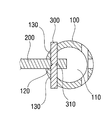
상기 목적을 달성하기 위하여 본 발명의 차선분리대는, 다수개로 이루어진 지주대(100); 상기 지주대(100) 사이에 가로로 길게 장착되는 가로연결대(200); 상기 지주대(100)와 상기 가로연결대(200)에 관통 삽입되어 상기 가로연결대(200)를 상기 지주대(100)에 고정시키는 고정핀(300); 을 포함하되, 상기 고정핀(300)은 상기 지주대(100) 및 상기 가로연결대(200)보다 강도가 약한 재질로 이루어진다.In order to achieve the above object, the lane separator of the present invention includes a plurality of props (100); A horizontal connecting
상기 지주대(100)의 내부에는 상하 관통된 관통공(110)이 형성되며, 외주면에는 상기 가로연결대(200)가 삽입되며 상기 관통공(110)과 연결된 삽입홈(120)이 형성되고, 상기 삽입홈(120)을 기준으로 양측에는 상기 고정핀(300)이 삽입되는 제1결합홈(130)이 각각 형성되며, 상기 가로연결대(200)에는 상기 삽입홈(120)에 삽입 배치될 때 상기 제1결합홈(130)과 일직선 상에 배치되는 제2결합홈(210)이 형성되고, 상기 삽입홈(120)에 상기 가로연결대(200)가 삽입된 상태에서 상기 고정핀(300)은 상기 제1결합홈(130)과 상기 제2결합홈(210)에 관통 삽입되어 상기 가로연결대(200)를 상기 지주대(100)에 고정시킨다.The upper and lower through
상기 가로연결대(200)는 두께보다 상하 높이가 더 높게 형성된다.The horizontal connecting
상기 지주대(100)에는 재귀 반사기능을 갖는 반사지(400)가 구비되되,The holding table 100 is provided with a
상기 반사지(400)는 길이 방향으로 길게 형성되며, 다수개로 이루어져 원주 방향으로 일정 각도 이격 배치되고, 상기 지주대(100)의 정면에서 상기 가로연결대(200)의 반대 방향으로 배치되는 것을 특징으로 하는 차선분리대.The
상기 고정핀(300)의 외주면에는 분리홈(310)이 형성된다.
이상에서 설명한 바와 같은 본 발명의 차선분리대는 다음과 같은 효과가 있다.The lane separator of the present invention as described above has the following effects.
상기 지주대(100)와 상기 가로연결대(200)를 상호 결합시키는 상기 고정핀(300)이 상기 지주대(100) 및 상기 가로연결대(200)보다 강도가 약한 재질로 구성됨으로써, 상기 고정핀(300)이 충격 발생시 쉽게 파손되어 상기 지주대(100)와 상기 가로연결대(200)가 분리되며, 이로 인해 상기 지주대(100)와 상기 가로연결대(200)가쉽게 파손되는 것을 방지할수 있게 된다.The
또한, 상기 지주대(100)와 상기 가로연결대(200)가 파손된 비산물이 도로면에 노출되는 것을 방지하여 2차 사고의 발생을 방지할 수 있는 효과가 있다.In addition, there is an effect that can prevent the occurrence of secondary accidents by preventing the by-products damaged by the
도 1은 본 발명의 실시예에 따른 차선분리대의 사시도,
도 2는 본 발명의 실시예에 따른 차선분리대의 분해사시도,
도 3은 본 발명의 실시예에 따른 차선분리대 단면 구조도,
도 4는 본 발명의 실시예에 따른 차선분리대의 차량 충돌시 분리과정을 설명하기 위한 단면 구조도,
도 5는 본 발명의 다른 실시예에 따른 차선분리대의 단면 구조도이다.1 is a perspective view of a lane separator according to an embodiment of the present invention;
2 is an exploded perspective view of a lane separator according to an embodiment of the present invention;
3 is a cross-sectional structure diagram of a lane separator according to an embodiment of the present invention;
4 is a cross-sectional structural view for explaining a separation process during a vehicle collision of a lane separator according to an embodiment of the present invention;
5 is a cross-sectional structural view of a lane separator according to another embodiment of the present invention.
도 1은 본 발명의 실시예에 따른 차선분리대의 사시도, 도 2는 본 발명의 실시예에 따른 차선분리대의 분해사시도, 도 3은 본 발명의 실시예에 따른 차선분리대 단면 구조도, 도 4는 본 발명의 실시예에 따른 차선분리대의 차량 충돌시 분리과정을 설명하기 위한 단면 구조도, 도 5는 본 발명의 다른 실시예에 따른 차선분리대의 단면 구조도이다.1 is a perspective view of a lane separator according to an embodiment of the present invention, FIG. 2 is an exploded perspective view of a lane separator according to an embodiment of the present invention, FIG. 3 is a cross-sectional structure diagram of a lane separator according to an embodiment of the present invention, and FIG. Sectional structural diagram for explaining a separation process when a vehicle collision of a lane separator according to an embodiment of the present invention, Figure 5 is a cross-sectional structural diagram of a lane separator according to another embodiment of the present invention.
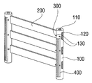
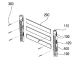
도 1 내지 도 4에 도시된 바와 같이, 본 발명의 실시예에 따른 차선분리대는, 지주대(100), 가로연결대(200), 고정핀(300), 반사지(400)로 이루어진다.As shown in Figures 1 to 4, the lane separator according to an embodiment of the present invention, the
상기 지주대(100)는 상기 가로연결대(200)를 지지하는 기둥으로서, 원통형의 기둥 형상이며, 금속재질로 이루어진다.The
상기 지주대(100)는, 차량과 충돌시 쉽게 부러지지 않고, 사고 발생 후에도 본래의 형성과 기능을 유지할 수 있는 재질로 이루어지는데, 주로 금속 재질로 이루어지고, RS-FITI-2010-032(지식경제부 공고 제2011-241호)에 따라 몸체성능을 만족해야 한다.The
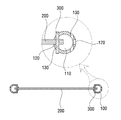
또한, 상기 지주대(100)의 내부에는 상하 관통된 관통공(110)이 형성되며, 외주면에는 상기 가로연결대(200)가 삽입되는 삽입홈(120)이 형성된다.In addition, the upper and lower through-
상기 삽입홈(120)은 측방향으로 관통 형성된 것으로, 3개로 이루어져 상하 이격 배치되며, 상기 관통공(110)과 연결된다.The
또한, 상기 지주대(100)에는 상기 삽입홈(120)을 기준으로 양측에 후술할 상기 고정핀(300)이 삽입되는 제1결합홈(130)이 각각 형성된다.In addition, the
상기 제1결합홈(130)은 양측으로 관통 형성되며, 상기 관통공(110) 및 상기 삽입홈(120)과 연결된다.The
상기 제1결합홈(130)은 1개의 상기 삽입홈(120)에 1개씩 배치되므로, 상기 결합홈은 상기 삽입홈(120)과 마찬가지로 3개로 구성된다.Since the
이러한 상기 지주대(100)는 최소 2개 이상으로 이루어지며, 2개의 상기 지주대(100) 사이에는 상기 가로연결대(200)가 구비된다.The
상기 가로연결대(200)는 2개의 상기 지주대(100) 사이에 장착되는 것으로, 가로로 긴 막대 형상으로 형성되고, 2개의 상기 지주대(100) 사이에는 3개의 상기 가로연결대(200)가 상하 이격되게 장착된다.The
상기 가로연결대(200)는 상기 지주대(100)와 마찬가지로 차량과 충돌시 쉽게 부러지지 않는 재질로 이루어지며, 상기 지주대(100)와 마찬가지로 RS-FITI-2010-032(지식경제부 공고 제2011-241호)에 따라 몸체성능을 만족해야 한다.The horizontal connecting
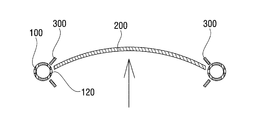
여기에서 상기 가로연결대(200)는 차량충돌시 충격을 흡수하기 위해 일정한 탄성을 갖는 것이 바람직하다. Here, the horizontal connecting
즉, 도 4에 도시된 바와 같이, 상기 가로연결대(200)에 두께 방향으로 충격이 가해지면 상기 가로연결대(200)는 휘어지면서 상기 삽입홈(120)에서 이탈하게 된다.That is, as shown in FIG. 4, when an impact is applied to the
또한, 상기 가로연결대(200)는 상하 높이가 두께보다 높게 형성된 것으로, 상하 방향으로는 일반 성인의 하중에도 형상 변화가 없을 정도의 강도를 가져야 한다.In addition, the
이러한 상기 가로연결대(200)에는 후술할 상기 고정핀(300)이 삽입되는 제2결합홈(210)이 형성된다.The
상기 제2결합홈(210)은 상기 가로연결대(200)의 두께 방향으로 관통 형성되며, 상기 가로연결대(200)의 양 끝단에 하나씩 형성되고, 상기 가로연결대(200)가 상기 삽입홈(120)에 삽입될 때 상기 제1결합홈(130)과 일직선상에 배치된다.The second coupling groove 210 is formed to penetrate in the thickness direction of the
한편, 상기 고정핀(300)은 상기 제1결합홈(130)과 상기 제2결합홈(210)에 관통 삽입되어 상기 지주대(100)와 상기 가로연결대(200)를 결합시키는 것으로, 원통형의 막대 형상으로 형성되며, 상기 지주대(100) 및 상기 가로연결대(200)보다 강도가 약한 재질로 이루어진다.On the other hand, the
이러한 상기 고정핀(300)은 상기 가로연결대(200)에 차량이 충돌했을 때 쉽게 부러지는 재질로 이루어져, 충돌 발생시 상기 가로연결대(200)가 상기 지주대(100)에 쉽게 분리되도록 한다.The
종래의 차선분리대는 상기 고정핀(300)이 파손되지 않아 상기 지주대(100)나 상기 가로연결대(200)가 파손되어 유지면에서 많은 비용이 발생하게 되는데, 본 발명의 실시예에 따른 상기 고정핀(300)은 충격 발생시 쉽게 파손되어 상기 지주대(100)와 상기 가로연결대(200)가 파손되지 않는다.In the conventional lane separator, the
또한, 상기 지주대(100)와 상기 가로연결대(200)가 파손된 비산물이 도로면에 노출되는 것을 방지하여 2차사고의 발생을 방지할 수 있는 효과가 있다.In addition, it is possible to prevent the occurrence of the secondary accident by preventing the by-products damaged by the
한편, 상기 반사지(400)는 상기 지주대(100)에 부착되어 운전자의 시선을 유도하게 되는데, RS-FITI-2010-032(지식경제부 공고 제2011-241호)에 따른 재귀반사기능을 갖는 재질이어야 한다.On the other hand, the
특히, 상기 반사지(400)는 길이 방향, 즉 수직 방향으로 길게 형성되며, 다수개로 이루어져 원주 방향으로 따라 일정 간격 이격 배치된다.In particular, the
여기에서 상기 반사지(400)는 상기 지주대(100)의 정면에서부터 원주를 따라 상기 가로연결대(200)의 반대 방향으로 배치되며, 차량이 상기 반사지(400)의 반사각도 유효범위에 배치되어 식별이 용이하도록 한다.Here, the
이와 같이 상기 지주대(100)에 상기 반사지(400)가 부착됨으로써, 운전자가 차선분리대의 식별을 용이하게 하여 차량과의 접촉 등의 사고를 예방하고, 파손을 줄일 수 있는 효과가 발생 된다.As such, the
한편, 경우에 따라 상기 고정핀(300)에는 외부 충격 발생시 쉽게 파손되도록 분리홈(310)이 형성될 수 있다.On the other hand, in some cases, the
도 4에 도시된 바와 같이 상기 분리홈(310)은 상기 고정핀(300)의 가운데 양측에 'V'자 형상으로 형성되며, 상기 가로연결대(200)의 상기 제2결합홈(210)에 삽입 배치된다.As shown in FIG. 4, the
이러한 상기 분리홈(310)은 상기 가로연결대(200)에 차량이 충돌했을 때 상기 가로연결대(200)가 상기 분리홈(310)을 가압하여 상기 고정핀(300)이 부러지게 되며, 상기 가로연결대(200)는 상기 삽입홈(120)에서 이탈된다.The
이와 같이 상기 고정핀(300)에 상기 분리홈(310)이 형성됨으로써, 차량 충돌시 상기 가로연결대(200)가 상기 지주대(100)에서 쉽게 분리되어 상기 지주대(100)와 상기 가로연결대(200)의 손상을 최소화 하는 효과가 발생 된다.As the
본 발명은 이에 한정되지 않으며, 이하의 부속 청구 범위의 사상 및 영역을 이탈하지 않는 범위 내에서 당업자에 의해 여러 형태로 변형 실시될 수 있으며, 따라서 이와 같은 변형은 본 발명의 영역 내에 있는 것으로 해석해야 할 것이다. The present invention is not limited thereto, and the present invention may be modified in various forms by those skilled in the art without departing from the spirit and scope of the appended claims, and such modifications should be construed as being within the scope of the present invention. something to do.
100 : 지주대
110 : 관통공
120 : 삽입홈
130 : 제1결합홈
200 : 가로연결대
210 : 제2결합홈
300 : 고정홈
310 : 분리홈
400 : 반사지100: holding post 110: through hole
120: insertion groove 130: the first coupling groove
200: horizontal connection 210: second coupling groove
300: fixing groove 310: separation groove
400: reflector
Claims (5)
상기 지주대(100) 사이에 가로로 길게 장착되는 가로연결대(200);
상기 지주대(100)와 상기 가로연결대(200)에 관통 삽입되어 상기 가로연결대(200)를 상기 지주대(100)에 고정시키는 고정핀(300); 을 포함하되,
상기 고정핀(300)은 상기 지주대(100) 및 상기 가로연결대(200)보다 강도가 약한 재질로 이루어지는 것을 특징으로 하는 차선분리대.
Holding stand 100 made of a plurality;
A horizontal connecting rod 200 mounted horizontally between the holding posts 100;
A fixing pin 300 inserted into the support post 100 and the horizontal connecting member 200 to fix the horizontal connecting member 200 to the supporting member 100; Including,
The fixing pin 300 is a lane separator, characterized in that made of a material that is weaker than the holding pole (100) and the horizontal connecting rod (200).
상기 지주대(100)의 내부에는 상하 관통된 관통공(110)이 형성되며, 외주면에는 상기 가로연결대(200)가 삽입되며 상기 관통공(110)과 연결된 삽입홈(120)이 형성되고, 상기 삽입홈(120)을 기준으로 양측에는 상기 고정핀(300)이 삽입되는 제1결합홈(130)이 각각 형성되며,
상기 가로연결대(200)에는 상기 삽입홈(120)에 삽입 배치될 때 상기 제1결합홈(130)과 일직선 상에 배치되는 제2결합홈(210)이 형성되고,
상기 삽입홈(120)에 상기 가로연결대(200)가 삽입된 상태에서 상기 고정핀(300)은 상기 제1결합홈(130)과 상기 제2결합홈(210)에 관통 삽입되어 상기 가로연결대(200)를 상기 지주대(100)에 고정시키는 것을 특징으로 하는 차선분리대.
The method of claim 1
The upper and lower through-holes 110 are formed inside the support stand 100, and the horizontal connecting rod 200 is inserted into an outer circumferential surface thereof, and an insertion groove 120 connected to the through-hole 110 is formed. First coupling grooves 130 into which the fixing pin 300 is inserted are formed at both sides of the insertion groove 120, respectively.
The horizontal coupling 200 is formed with a second coupling groove 210 is disposed in a straight line with the first coupling groove 130 when it is inserted into the insertion groove 120,
The fixing pin 300 is inserted through the first coupling groove 130 and the second coupling groove 210 in the state in which the horizontal connecting rod 200 is inserted into the insertion groove 120 and the horizontal connecting rod ( Lane separation table, characterized in that fixed to the holding (100) (200).
상기 가로연결대(200)는 두께보다 상하 높이가 더 높게 형성되는 것을 특징으로 하는 차선분리대.
The method of claim 2
The horizontal connecting rod 200 is a lane separator, characterized in that the vertical height is formed higher than the thickness.
상기 지주대(100)에는 재귀 반사기능을 갖는 반사지(400)가 구비되되,
상기 반사지(400)는 길이 방향으로 길게 형성되며, 다수개로 이루어져 원주 방향으로 일정 각도 이격 배치되고, 상기 지주대(100)의 정면에서 상기 가로연결대(200)의 반대 방향으로 배치되는 것을 특징으로 하는 차선분리대.
The method of claim 2
The holding table 100 is provided with a reflector 400 having a retroreflective function,
The reflective paper 400 is formed long in the longitudinal direction, it is composed of a plurality of spaced apart at a predetermined angle in the circumferential direction, characterized in that disposed in the opposite direction of the horizontal connecting rod 200 from the front of the holding table (100) Lane Separator.
상기 고정핀(300)의 외주면에는 분리홈(310)이 형성되는 것을 특징으로 하는 차선분리대.The method of claim 2
Lane separation table, characterized in that the separation groove 310 is formed on the outer peripheral surface of the fixing pin (300).
Priority Applications (1)
| Application Number | Priority Date | Filing Date | Title |
|---|---|---|---|
| KR1020180043795A KR102126738B1 (en) | 2018-04-16 | 2018-04-16 | Lanes separator |
Applications Claiming Priority (1)
| Application Number | Priority Date | Filing Date | Title |
|---|---|---|---|
| KR1020180043795A KR102126738B1 (en) | 2018-04-16 | 2018-04-16 | Lanes separator |
Publications (2)
| Publication Number | Publication Date |
|---|---|
| KR20190120511A true KR20190120511A (en) | 2019-10-24 |
| KR102126738B1 KR102126738B1 (en) | 2020-06-25 |
Family
ID=68423621
Family Applications (1)
| Application Number | Title | Priority Date | Filing Date |
|---|---|---|---|
| KR1020180043795A KR102126738B1 (en) | 2018-04-16 | 2018-04-16 | Lanes separator |
Country Status (1)
| Country | Link |
|---|---|
| KR (1) | KR102126738B1 (en) |
Cited By (1)
| Publication number | Priority date | Publication date | Assignee | Title |
|---|---|---|---|---|
| KR102428361B1 (en) | 2021-12-03 | 2022-08-02 | 설지훈 | Crossbar for Lane Separator |
Citations (4)
| Publication number | Priority date | Publication date | Assignee | Title |
|---|---|---|---|---|
| KR200401490Y1 (en) * | 2005-08-19 | 2005-11-17 | 신도산업 주식회사 | Built-up type Guard Fence |
| KR200405969Y1 (en) * | 2005-10-21 | 2006-01-11 | 송부욱 | The fence pole |
| KR20120038830A (en) * | 2010-10-14 | 2012-04-24 | 주식회사 지오그램 | That is guide rail for road that equip shock suction of shock-absorbing member |
| KR101152420B1 (en) * | 2011-12-07 | 2012-06-07 | 조주영 | Prefabrication the timber fence |
-
2018
- 2018-04-16 KR KR1020180043795A patent/KR102126738B1/en active IP Right Grant
Patent Citations (4)
| Publication number | Priority date | Publication date | Assignee | Title |
|---|---|---|---|---|
| KR200401490Y1 (en) * | 2005-08-19 | 2005-11-17 | 신도산업 주식회사 | Built-up type Guard Fence |
| KR200405969Y1 (en) * | 2005-10-21 | 2006-01-11 | 송부욱 | The fence pole |
| KR20120038830A (en) * | 2010-10-14 | 2012-04-24 | 주식회사 지오그램 | That is guide rail for road that equip shock suction of shock-absorbing member |
| KR101152420B1 (en) * | 2011-12-07 | 2012-06-07 | 조주영 | Prefabrication the timber fence |
Cited By (1)
| Publication number | Priority date | Publication date | Assignee | Title |
|---|---|---|---|---|
| KR102428361B1 (en) | 2021-12-03 | 2022-08-02 | 설지훈 | Crossbar for Lane Separator |
Also Published As
| Publication number | Publication date |
|---|---|
| KR102126738B1 (en) | 2020-06-25 |
Similar Documents
| Publication | Publication Date | Title |
|---|---|---|
| KR101913838B1 (en) | Fence | |
| KR102126738B1 (en) | Lanes separator | |
| KR200391835Y1 (en) | Complex guard fence for vehicle | |
| KR200391781Y1 (en) | Structure of supporter for guardrail | |
| KR101630851B1 (en) | Safety fence for shock-absorbing using elastic joint, and method for constructing this same | |
| KR101507481B1 (en) | Median strip for shock absorber | |
| KR101103716B1 (en) | Post Fracture Area Connecting Structure | |
| KR101288063B1 (en) | Guardrail for a bridge | |
| KR101757260B1 (en) | Fence for preventing jaywalking and, method for constructing this same | |
| CN108385564A (en) | A kind of safety type combined type guardrail | |
| KR100974853B1 (en) | Median Strip | |
| CN214219500U (en) | Road bridge collision avoidance device | |
| KR200383560Y1 (en) | A guard rail provide with safety sock-absorber device | |
| CN210086123U (en) | Road and bridge safety barrier | |
| KR101284786B1 (en) | Guard rail | |
| KR20120038050A (en) | Median strip guardrail equipped with buffer structure | |
| KR100942674B1 (en) | Safety barrier | |
| KR200376094Y1 (en) | A guard rail provide with shock-absorber | |
| CN219117945U (en) | Anticollision bridge guardrail | |
| KR20040012654A (en) | Guard beam for protecting cars impact | |
| KR101181429B1 (en) | Guardrails for Absorption of Impact | |
| CN205276175U (en) | Guardrail unit and guardrail | |
| CN215329587U (en) | Cold region SBm-level snow-resistant combined type opening guardrail | |
| CN213267511U (en) | Guardrail for road and bridge | |
| KR101286738B1 (en) | strips for road |
Legal Events
| Date | Code | Title | Description |
|---|---|---|---|
| A201 | Request for examination | ||
| A302 | Request for accelerated examination | ||
| E902 | Notification of reason for refusal | ||
| AMND | Amendment | ||
| E601 | Decision to refuse application | ||
| AMND | Amendment | ||
| E90F | Notification of reason for final refusal | ||
| AMND | Amendment | ||
| J201 | Request for trial against refusal decision | ||
| J301 | Trial decision |
Free format text: TRIAL NUMBER: 2019101002832; TRIAL DECISION FOR APPEAL AGAINST DECISION TO DECLINE REFUSAL REQUESTED 20190823 Effective date: 20200529 |
|
| GRNO | Decision to grant (after opposition) |